x-ray polarimetry with gas pixel detectors: a new window
TRANSCRIPT

ARTICLE IN PRESS
0168-9002/$ - se
doi:10.1016/j.ni
�CorrespondE-mail addr
Nuclear Instruments and Methods in Physics Research A 576 (2007) 183–190
www.elsevier.com/locate/nima
X-ray polarimetry with Gas Pixel Detectors:A new window on the X-ray sky
R. Bellazzinia,�, G. Spandrea, M. Minutia, L. Baldinia, A. Breza, F. Cavalcaa,b,L. Latronicoa, N. Omodeia, M. Razzanoa,b, F. Angelinia,b, M.M. Massaia,b,
C. Sgroa, Enrico Costac, Paolo Soffittac
aINFN sez. Pisa, Largo B. Pontecorvo, 3 I-56127 Pisa, ItalybDipartimento di Fisica, Universita di Pisa, Largo B. Pontecorvo, 3 I-56127 Pisa, Italy
cIstituto di Astrofsica Spaziale e Fisica Cosmica, Via del Fosso del Cavaliere 100, I-00133 Roma, Italy
Available online 6 February 2007
Abstract
We report on a new instrument that brings high sensitivity to X-ray polarimetry, which is the last unexplored field of X-ray astronomy.
It derives the polarization information from the track of the photoelectrons imaged by a finely subdivided Gas Pixel Detector. The device
can also do simultaneously good imaging (50–100 mm), moderate spectroscopy (�15% at 6 keV) and fast, high rate timing down to
150 eV. Moreover, being truly 2D, it is non-dispersive and does not require any rotation. The great improvement of sensitivity, at least
two orders of magnitude with respect to traditional polarimeters (based on Bragg crystals or Thomson scattering), will allow the direct
exploration of the most dramatic objects of the X-ray sky. At the focus of the large mirror area of the XEUS telescope, it will be decisive
in reaching many of the scientific goals of the mission. With integration times of the order of 1 day polarimetry of Active Galactic Nuclei
at the per cent level will be possible, a real breakthrough in high-energy astrophysics.
r 2007 Elsevier B.V. All rights reserved.
PACS: 52.70.�m; 52.70.La; 07.85.�m
Keywords: Gas Pixel Detectors; ASIC; X-ray polarimetry
1. Introduction
If we look back to the history of X-ray astronomy, wecan say that after the first pioneering activity with rocketsthe sequence UHURU, Einstein, Chandra, following apath tracked by R. Giacconi, has been the backbone of thisactivity that nowadays has arrived at a turning point. Nomajor mission is presently established and ideas about howsuch a mission should be designed are not clear. Chandrahas shown the great capabilities of optics at the sub-arcsecond level. Both Chandra and XMM-Newton haveopened the window of high-resolution spectroscopy. Insome sense, these two missions have brought X-rayastronomy much closer to optical astronomy, but when
e front matter r 2007 Elsevier B.V. All rights reserved.
ma.2007.01.149
ing author. Tel.: +39 050 2214 367; fax: +39 050 2214 317.
ess: [email protected] (R. Bellazzini).
we convert the effective areas of these telescopes intoequivalent diameters we see that from the collectioncapability, they are equivalent to medium level opticalamateur telescopes, although equipped with high-perfor-mance focal plane instrumentations.These gave rise to the need of a new generation telescope
with a collecting area two orders of magnitude higher, whilestill preserving an angular resolution at the arcsecond level,which is imperative to study crowded deep fields and thusavoiding source confusion. The availability of the Interna-tional Space Station (ISS) suggested that such a telescopecould be assembled in orbit, so bypassing the limits of launchvehicles. The fog that is folding the future of the ISS and thegeneral decline of funds for space-based astronomicalresearch have suggested a less ambitious solution.The present XEUS design is based on a telescope
of completely new technology, drastically reducing the

ARTICLE IN PRESSR. Bellazzini et al. / Nuclear Instruments and Methods in Physics Research A 576 (2007) 183–190184
weight to area ratio, with an effective area of the order of5m2 and a focal length of 35m, harbored on one satellite.A second satellite will be launched with a complex focalplane instrumentation locked to the first in formationflight.
The ensemble shall be placed in an L2 orbit.The focal plane would be based on two major instru-
ments, a micro-calorimeter array based on TES technologyand a Wide Field Imager based on APS technology. Thesetwo instruments will be the drivers for the study of remoteUniverse, explore the formation of large-scale structures,the role of black holes and their interaction with galaxies.However, they will provide as well the capability to studydeep physics of more bright objects. To this purpose, theXEUS team is foreseeing the possibility to include moreinstrumentations, mainly devoted to a more restrictedpopulation of objects, but capable to address questions ofextreme interest. These instrumentations include a photo-electric polarimeter named XPOL.
2. X-ray polarimetry
In optical astronomy, polarimetry is somehow a nichediscipline. In X-ray astronomy, it is expected to be a majortopic for various reasons:
�
The non-thermal emission processes, such as synchro-tron, cyclotron and non-thermal bremsstrahlung play asignificant role. They result in highly polarized radia-tion. X-ray polarimetry can enlighten the nature of theemission. � The transfer of radiation from the emitting region to theobserver undergoes various processes that can result in arelevant polarization.
� In compact objects, the radiation is scattered by regionswhose geometry is far from spherical symmetry,including accretion disks and accretion columns. Theselection of scattering angle in the direction of theobserver results in polarization, according to theCompton/Thomson cross-sections. The scattering canmodify the spectrum if the region is at high temperatureor simply remove a part of the photons, which arephotoabsorbed. This last process of scattering is usuallynamed reflection and is marked by the presence of Fe Kfluorescence photons (obviously unpolarized).
� In the presence of very high magnetic fields, theradiation can be polarized by the combined effect ofdifferential cross-sections for the scattering of normaland anomalous modes in the plasma and vacuumbirefringence, as predicted by quantum electrodynamics.
� In extended objects with thermal collisional equilibrium,such as clusters of galaxies, if the plasma is thin for thecontinuum and thick for resonance lines, the angle oflast scattering in the direction of the observer will beselective and different in each part of the clusterresulting in an angular dependent polarization of theline photons.
�
If some theories of quantum gravity based on theviolation of the Lorentz invariance are true, the vacuumis birefringent and the plane of polarization of photonsshould rotate by an amount that increases with energyand with distance. The detection of this effect would beof the highest interest. X-ray polarimetry can performthis test at highest energies and on long baselines bymeasuring the (expected) polarization of BL Lac objectsand GRB afterglows on the Gpc scale. � More in general, a vast literature distributed over almost40 years has made many predictions of the expectedpolarization from most classes of X-ray sources. Yet, theonly positive detection has been, until now, that of theCrab Nebula, first with a rocket then with the OSO-8satellite. This is one of the brightest sources in the X-raysky, while many of the predictions refer to much faintersources.
3. The Gas Pixel Detector as X-ray polarimeter
Schematically, a Gas Pixel Detector (GPD) for X-raypolarimetry is made by a gas cell with a Berillium window,a Gas Electron Multiplier (GEM) which amplifies thecharge of the electron tracks generated in the drift gapproviding energy and time information and a pixellatedcharge collection plane directly connected to the analogread-out electronics.In the photoelectron absorption of polarized X-rays, a
‘‘cos2’’ modulation is observed with respect to theazimuthal angle j between the direction of emission ofthe photoelectron and the polarization vector. Withmodern GPDs, it is possible to image, with high accuracy,the single photoelectron track and to derive the impactpoint, which differs from the barycenter. Consequently, theinitial direction of the photoelectron path before it israndomized by the collisions with the gas molecules isdetermined. Degree and polarization angle of the X-rayphoton is obtained from the distribution of the emissionangles. It is worth noticing that the isotropically emittedAuger electron is instead not modulated by the X-raypolarization and therefore it represents a disturbance,especially at low energy.The concept of GPD [1–3] was first developed in 2001,
with a technology based on multilayer printed circuit board(PCB) with vias which brought the signals from the read-out plane, patterned with square pixels at 200 mm pitch, tothe read-out electronics. The PCB technique limited thenumber of channels (1000–2000) and the pitch of the pixels(100–200 mm). Also, long paths to bring the signals werecapacitatively coupled to each other. The jump inthe number of channels (hence in the coverage area andthe FOV) and the decrease in the pixel pitch (hence in theresponse to lower energy and the eventual use at highpressure) were made possible by designing and building anASIC CMOS multilayer chip. The top metal layer ispatterned in a honeycomb hexagonal pattern, which is the

ARTICLE IN PRESSR. Bellazzini et al. / Nuclear Instruments and Methods in Physics Research A 576 (2007) 183–190 185
read-out plane of the charge produced by the photoelec-trons. Each pixel is connected to a full electronics chain(pre-amplifer, shaping amplifer, sample and hold, multi-plexer) built immediately below it, exploiting the remainingfive layers of the VLSI CMOS technology. Three genera-tions of chips have been developed so far with increasingarea and throughput (Fig. 1).
The first VLSI CMOS chip (chip I) having 4mmdiameter, 2101 pixel chip and 80 mm pitch, was providedwith external trigger and downloading of all the framepixels with a rate capability of about 1 kHz. The secondgeneration of chips, squared 1.1 cm� 1.1 cm (chip II), waspatterned with 22,000 pixels organized in eight independentsub-frames of 2700 pixels with external or internal trigger.The frames can be read out in parallel providing a framerate of 1–2 kHz. The third and current generation of chip(chip III) is provided with unique characteristics to be usedwith the best performances for X-ray polarimetry.
The chip has 105,600 hexagonal pixels arranged at 50 mmpitch in a 300� 352 honeycomb matrix, corresponding toan active area of 15� 15mm2 with a pixel density of470mm�2. Each pixel is connected to a charge-sensitiveamplifier followed by a shaping circuit and a sample &hold-multiplexer circuit. The chip integrates more than16.5 million transistors and it is subdivided in 16 identicalclusters of 6600 pixels (22 rows of 300 pixels) oralternatively in 8 clusters of 13,200 pixels (44 rows of 300pixels), each one with an independent differential analogoutput buffer (Fig. 2).
Each cluster has a customizable internal self-triggeringcapability with independently adjustable thresholds. Every4 pixels (mini-cluster, Fig. 3) contribute to a local triggerwith a dedicated amplifier whose shaping time(Tshaping�1.5 ms) is roughly a factor 2 faster than theshaping time of the analog charge signal. The contributionof any pixel to the trigger can be disabled by directaddressing of the pixel. An internal wired-OR combination
Fig. 1. The three chip generations in comparison. The last version with
105.600 pixels is shown bonded to its ceramic package (304 pins).
of each mini-cluster self-triggering circuit holds themaximum of the shaped signal on each pixel. The eventis localized in a rectangular area containing all triggeredmini-clusters plus a user selectable margin of 10 or 20pixels. The Xmin, Xmax and Ymin, Ymax rectangle coordi-nates are available as four 9-bit data outputs as soon as thedata acquisition process following an internally triggeredevent has terminated, flagged by the DataReady output.The event window coordinates can be copied into aSerial–Parallel IO interface register (a 36-stage FIFO) byapplying an external command signal (ReadMinMax).Subsequently, clock pulses push out the analog data to aserial balanced output buffer compatible with the inputstage of the Texas Instruments 12-bit flash ADC ADS572x.In self-trigger operation, the read-out time and the
amount of data to be transferred result vastly reduced(at least a factor 100) with respect to the standardsequential read-out mode of the full matrix (which is stillavailable, anyway). This is due to the relatively smallnumber of pixels (600–700) within the region of interest.Main characteristics of the chip are:
�
peaking time: 3–10 ms, externally adjustable; � full-scale linear range: 30,000 electrons; � pixel noise: 50 electrons ENC; � read-out mode: asynchronous or synchronous; � trigger mode: internal, external or self-trigger; � read-out clock: up to 10MHz; � self-trigger threshold: 2200 electrons (10% FS); � frame rate: up to 1 kHz in self-trigger mode (eventwindow);
� parallel analog output buffers: 1, 8 or 16; � access to pixel content: direct (single pixel) or serial(8–16 clusters, full matrix, region of interest);
� fill fraction (ratio of metal area to active area): 92%.A 50 mm thick GEM with 50 mm pitch holes on atriangular pattern has been assembled on top of chip. Theperfect matching of read-out and gas amplificationsampling allows to get optimal results and to fully exploitthe very high granularity of the device. The technologicalchallenge in the fabrication of this type of GEM was theprecise and uniform etching of very narrow charge multi-plication holes (30 and 15 mm diameter at the top and in themiddle of the kapton layer) on a GEM foil of standard50 mm thickness. The absorption region of the GPDbetween the GEM and the enclosure drift electrode(25 mm Aluminized Mylar foil) has been realized with a10mm spacer. The collection gap between the bottomGEM and the pixel matrix of the read-out chip is roughly1mm thick. The detector response has been studied withtwo different gas mixtures: our standard 50% Neon–50%DME mixture and a lighter one, composed by 40%Helium–60% DME. Typical high-voltage settings used inthe tests for the Neon based mixture are:VDRIFT ¼ �1800V, VGEM (top) ¼ �750V, VGEM(bottom) ¼ �300V, the read-out electrode being at �0V

ARTICLE IN PRESS
Fig. 3. The 4 pixel self-trigger mini-cluster definition.
Fig. 2. Simplified pixel layout.
Fig. 4. Photo during the assembly phase of the detector. The GEM foil
glued to bottom of the gas-tight enclosure and the large area ASIC
mounted on the control motherboard are well visible.
R. Bellazzini et al. / Nuclear Instruments and Methods in Physics Research A 576 (2007) 183–190186
ARTICLE IN PRESSR. Bellazzini et al. / Nuclear Instruments and Methods in Physics Research A 576 (2007) 183–190 187
(the charge preamp input voltage). The He-based mixturereaches the same gas gain at VGEM (top) ¼ �780V,essentially because of the larger DME content. The 50 mmpitch GEM has shown to work magnificently with both gasmixtures. It has a large effective gain (well above 1000) at amuch reduced voltage (at least 70V less) compared withour previous 90 mm pitch GEM. Likely, this is due to thehigher field lines density inside the very narrow amplifica-tion holes. A photo of the detector ready to be mounted onthe control motherboard is shown in Fig. 4.
A custom and very compact DAQ system to generateand handle command signals to/from the chip (implemen-ted on Altera FPGA Cyclone EP1C240), to read anddigitally convert the analog data (ADS5270TI Flash ADC)and to store them, temporarily, on a static RAM, has beendeveloped. By using the RISC processor NIOS II,embedded on Altera FPGA, and the self-triggeringfunctionality of the chip, it is possible, immediately afterthe event is read out, to acquire the pedestals ofthe pixels in the same chip-defined event window (regionof interest). The pedestals can be read one or moretimes (user-defined). The average of the pedestal readings isused to transfer pedestal-subtracted data to theoff-line analysis system. This mode of operation has thegreat advantage of allowing the real time control of thedata quality and to cancel any effect of time drift of thepedestal values or other temperature or environmentaleffects.
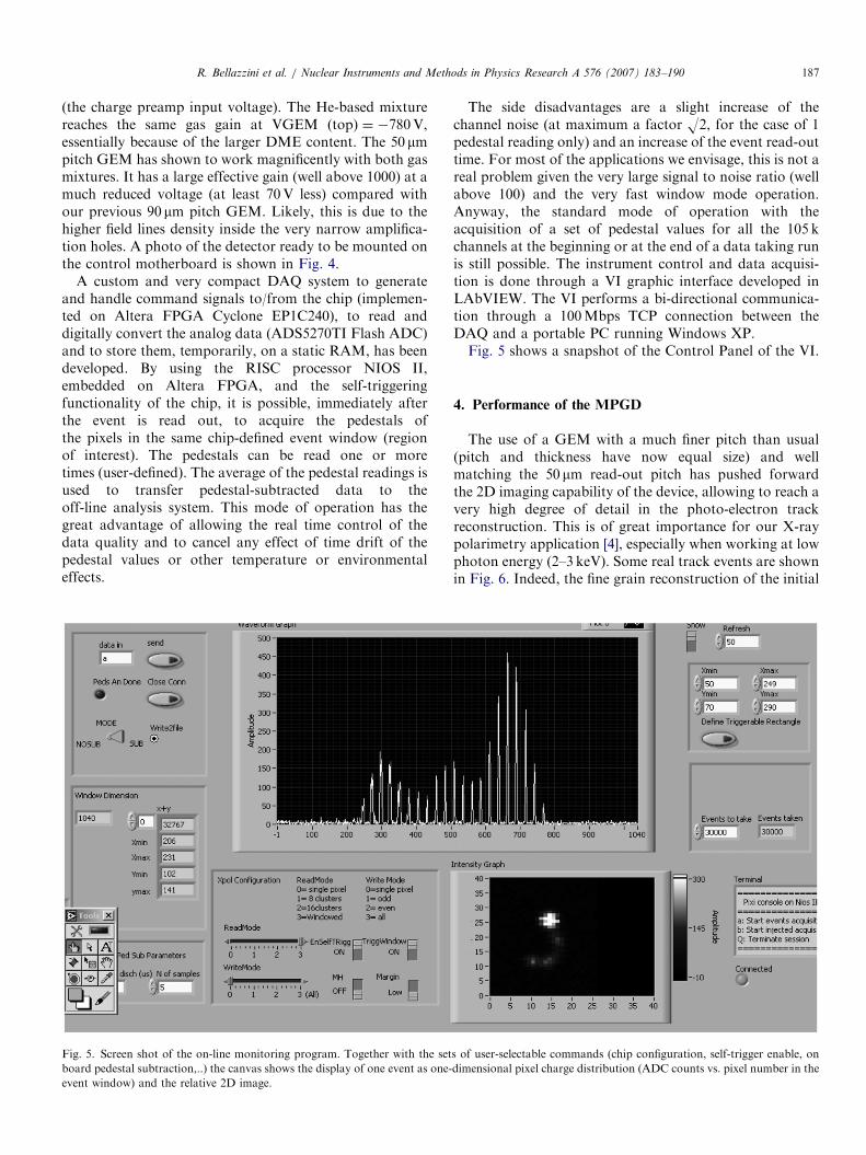
Fig. 5. Screen shot of the on-line monitoring program. Together with the set
board pedestal subtraction,..) the canvas shows the display of one event as one-
event window) and the relative 2D image.
The side disadvantages are a slight increase of thechannel noise (at maximum a factor O2, for the case of 1pedestal reading only) and an increase of the event read-outtime. For most of the applications we envisage, this is not areal problem given the very large signal to noise ratio (wellabove 100) and the very fast window mode operation.Anyway, the standard mode of operation with theacquisition of a set of pedestal values for all the 105 kchannels at the beginning or at the end of a data taking runis still possible. The instrument control and data acquisi-tion is done through a VI graphic interface developed inLAbVIEW. The VI performs a bi-directional communica-tion through a 100Mbps TCP connection between theDAQ and a portable PC running Windows XP.Fig. 5 shows a snapshot of the Control Panel of the VI.
4. Performance of the MPGD
The use of a GEM with a much finer pitch than usual(pitch and thickness have now equal size) and wellmatching the 50 mm read-out pitch has pushed forwardthe 2D imaging capability of the device, allowing to reach avery high degree of detail in the photo-electron trackreconstruction. This is of great importance for our X-raypolarimetry application [4], especially when working at lowphoton energy (2–3 keV). Some real track events are shownin Fig. 6. Indeed, the fine grain reconstruction of the initial
s of user-selectable commands (chip configuration, self-trigger enable, on
dimensional pixel charge distribution (ADC counts vs. pixel number in the

ARTICLE IN PRESS
Y c
oord
inate
(m
m)
-3.6
-3.8
-4
-4.2
-4.4
-4.6
-4.8
-5
1.8 2 2.2 2.4 2.6 2.8 3 3.2
X coordinate (mm)
Ne (50%) - DME (50%)
Y c
oord
inate
(m
m)
3.8
3.6
3.4
3.2
3
2.8
2.6
2.4
2.2
-1 -0.8 -0.6 -0.4 -0.2 0 0.2 0.4 0.6
X coordinate (mm)
He (40%) - DME (60%)
Event Number:
Number of Clusters:
Cluster Size (largest):
Pulse Height:
Signal to Noise:
Baricenter:
Conversion Point:
Second Mom Max:
Second Mom Min:
Shape (ratio of moments)
Third Mom Max:
Phi (iteration 1)
Phi (iteration 2)
Reconstructed Baricenter
Reconstructed Impact Pt.
Event Number:
Number of Clusters:
Cluster Size (largest):
Pulse Height:
Signal to Noise:
Baricenter:
Conversion Point:
Second Mom Max:
Second Mom Min:
Shape (ratio of moments)
Third Mom Max:
Phi (iteration 1)
Phi (iteration 2)
Reconstructed Baricenter
Reconstructed Impact Pt.
101
1
130
12208.2
320.1
2.50 -4.31
2.38 -4.01
0.0459
0.0134
3.42
-2.6e-03
-0.9540
-1.8518
25
1
121
10625.1
278.9
-0.15 2.95
-0.63 2.94
0.0475
0.0210
2.26
-1.1e-02
0.1949
-0.2401
Fig. 6. Real tracks obtained by irradiating the detector with X-rays from the Cr tube for two gas mixtures. The black cross refers to the barycenter
position and the black line to the direction of the principal axis (iteration 1); the red cross refers to the conversion point evaluation and the red line to the
emission direction of the photoelectron (iteration 2).
R. Bellazzini et al. / Nuclear Instruments and Methods in Physics Research A 576 (2007) 183–190188
part of the photoelectron track allows a better estimationof the emission direction and from the obtained angulardistribution a better evaluation of the degree and angle ofpolarization of the detected radiation.
Fig. 7 shows the cumulative hit map of 100 tracksobtained with photons from a Cr X-ray tube using a gasfilling of 40% Helium and 60% DME. This figure wellexplains how the detector works as X-ray polarimeter. Onan event by event basis, and without any rotation of theset-up, the direction of emission of the photoelectron canbe reconstructed and the modulation of correspondingangular distribution measured.
The very good imaging capability of the detector hasbeen tested by illuminating with a 55Fe source, from
above, a small pendant (few millimeter in size) placed infront of the detector. The radiographic image is obtainedby plotting both the barycenters and the conversion points(Fig. 8). It is worth to note how, for Neon- or He-basedmixtures, the accuracy of image reconstruction is muchbetter using the absorption point instead of the barycenter.In these light mixtures, where tracks are long with respectto the detector granularity, the barycenter can be quite faraway from the point of photon absorption. The measure-ment of the modulation factor for polarized photons hasbeen carried out by using radiation from a Cr X-ray tube(5.41 keV line). The X-ray beam is Thomson scatteredthrough a Li target (6mm in diameter, 70mm long),canned in a beryllium case (500 mm thick) in order to

ARTICLE IN PRESS
Fig. 8. Radiographic image of a small pendant obtained with photons
from a 55Fe source.
Fig. 7. Cumulative hit map of 100 photoelectron tracks in He
(40%)–DME (60%). Photons from Cr X-ray generator.
R. Bellazzini et al. / Nuclear Instruments and Methods in Physics Research A 576 (2007) 183–190 189
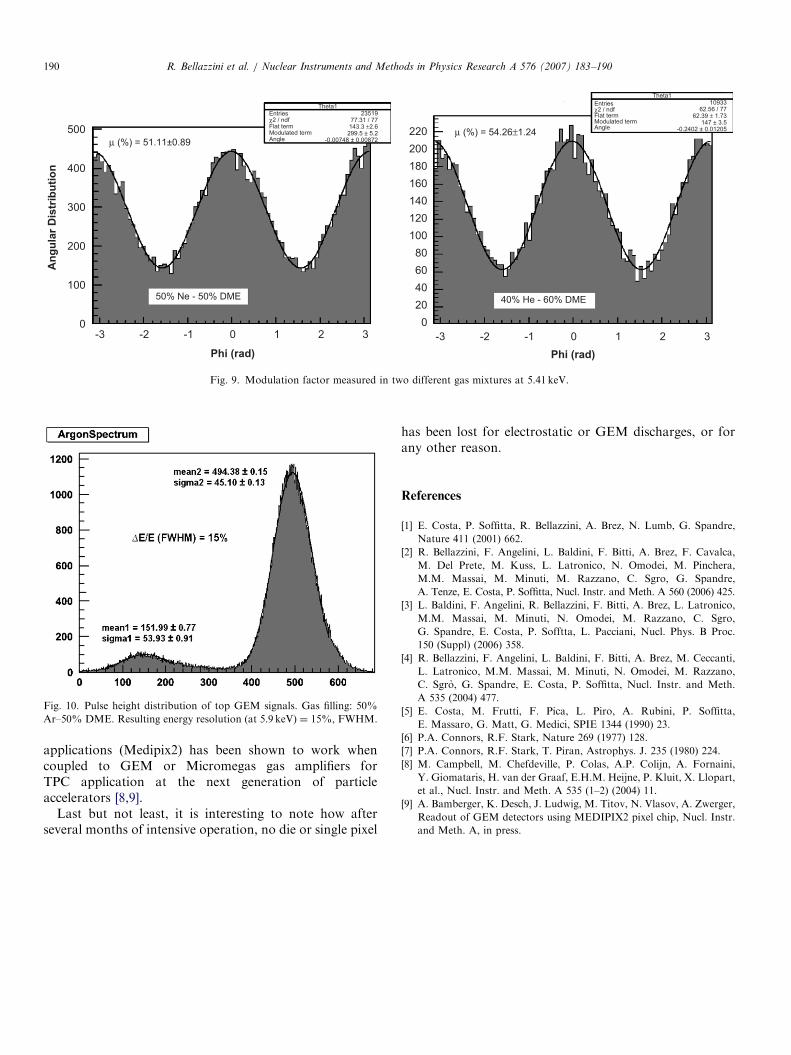
prevent oxidation and nitridation from air [5]. Thegeometry of the output window of the scatterer and thedistance with respect to the detector limit the scatteringangles to �901, so that the radiation impinging the detectoris highly linearly polarized (better than 98%). Fig. 9 showsthe modulation factor obtained in two different gasmixtures. Values of modulation of 51.1170.89% and54.2671.24% have been measured in 50% Ne–50% DMEand 40% He–60% DME, respectively. The GPD describedin this paper is not only an excellent imager but also a goodproportional counter with energy resolution of about14–15% at 5.9 keV, depending on the gas filling. Thisfeature is suitable for crucial energy resolved measure-ments, p.e. in polarimetry to separate the unpolarizedfluorescence from the partially polarized continuum inreflection spectra. This property will allow p.e. to testGeneral Relativity effects in the matter around a BlackHole through the measurement of the polarization angle asa function of energy [6,7]. Fig. 10 is the pulse heightdistribution of the signals from the top GEM at 5.9 keV in50% Ar–50% DME. At this energy DE/E�14%, FWHM,is measured.
5. Conclusions
With devices like the one described in this paper, theclass of GPDs has reached a level of integration,compactness and resolving power so far considered in thereach of solid state detectors only. As for the X-raypolarimetry application, the very low residual modulationand a modulation factor well above 50% will allowpolarimetric measurements at the level of �1% for
hundreds of galactic and extragalactic sources: a realbreakthrough in X-ray astronomy.It must be underlined also that, depending on type of
electron multiplier, pixel and die size, electronics shapingtime, analog vs. digital read-out, counting vs. integratingmode, many other applications can be envisaged for thisclass of detectors. As an example, we are now testing in thelab a UV photodetector with a semitransparent CsIphotocathode coupled to this chip. The device has singleelectron sensitivity and good imaging capability. Resultswill be reported soon.It is also worth noticing that following a similar
approach, a digital counting chip developed for medical
ARTICLE IN PRESSA
ng
ula
r D
istr
ibu
tio
n
500
400
300
200
100
0-3 -2 -1 0 1 2 3
Phi (rad)
50% Ne - 50% DME
μ (%) = 51.11±0.89μ (%) = 54.26±1.24
Theta1Entriesχ2 / ndfFlat termModulated termAngle
2351977.31 / 77143.3 ±2.6
-0.00748 ± 0.00872299.5 ± 5.2
Theta1
Entriesχ2 / ndfFlat termModulated termAngle
1093362.56 / 77
62.39 ± 1.73
-0.2402 ± 0.01205147 ± 3.5
220
200
180
160
140
120
100
80
60
40
20
0
-3 -2 -1 0 1 2 3
Phi (rad)
40% He - 60% DME
Fig. 9. Modulation factor measured in two different gas mixtures at 5.41 keV.
Fig. 10. Pulse height distribution of top GEM signals. Gas filling: 50%
Ar–50% DME. Resulting energy resolution (at 5.9 keV) ¼ 15%, FWHM.
R. Bellazzini et al. / Nuclear Instruments and Methods in Physics Research A 576 (2007) 183–190190
applications (Medipix2) has been shown to work whencoupled to GEM or Micromegas gas amplifiers forTPC application at the next generation of particleaccelerators [8,9].
Last but not least, it is interesting to note how afterseveral months of intensive operation, no die or single pixel
has been lost for electrostatic or GEM discharges, or forany other reason.
References
[1] E. Costa, P. Soffitta, R. Bellazzini, A. Brez, N. Lumb, G. Spandre,
Nature 411 (2001) 662.
[2] R. Bellazzini, F. Angelini, L. Baldini, F. Bitti, A. Brez, F. Cavalca,
M. Del Prete, M. Kuss, L. Latronico, N. Omodei, M. Pinchera,
M.M. Massai, M. Minuti, M. Razzano, C. Sgro, G. Spandre,
A. Tenze, E. Costa, P. Soffitta, Nucl. Instr. and Meth. A 560 (2006) 425.
[3] L. Baldini, F. Angelini, R. Bellazzini, F. Bitti, A. Brez, L. Latronico,
M.M. Massai, M. Minuti, N. Omodei, M. Razzano, C. Sgro,
G. Spandre, E. Costa, P. Sofftta, L. Pacciani, Nucl. Phys. B Proc.
150 (Suppl) (2006) 358.
[4] R. Bellazzini, F. Angelini, L. Baldini, F. Bitti, A. Brez, M. Ceccanti,
L. Latronico, M.M. Massai, M. Minuti, N. Omodei, M. Razzano,
C. Sgro, G. Spandre, E. Costa, P. Soffitta, Nucl. Instr. and Meth.
A 535 (2004) 477.
[5] E. Costa, M. Frutti, F. Pica, L. Piro, A. Rubini, P. Soffitta,
E. Massaro, G. Matt, G. Medici, SPIE 1344 (1990) 23.
[6] P.A. Connors, R.F. Stark, Nature 269 (1977) 128.
[7] P.A. Connors, R.F. Stark, T. Piran, Astrophys. J. 235 (1980) 224.
[8] M. Campbell, M. Chefdeville, P. Colas, A.P. Colijn, A. Fornaini,
Y. Giomataris, H. van der Graaf, E.H.M. Heijne, P. Kluit, X. Llopart,
et al., Nucl. Instr. and Meth. A 535 (1–2) (2004) 11.
[9] A. Bamberger, K. Desch, J. Ludwig, M. Titov, N. Vlasov, A. Zwerger,
Readout of GEM detectors using MEDIPIX2 pixel chip, Nucl. Instr.
and Meth. A, in press.