x-ray ct in metrology of geometric featureacta.fih.upt.ro/pdf/2014-1/acta-2014-1-09.pdf · computed...
TRANSCRIPT

ACTA TEHNICA CORVINIENSIS – Bulletin of Engineering Tome VII [2014] Fascicule 1 [January – March]
ISSN: 2067 – 3809
© copyright Faculty of Engineering - Hunedoara, University POLITEHNICA Timisoara
1. Michal WIECZOROWSKI, 2. Bartosz GAPINSKI
X-RAY CT IN METROLOGY OF
GEOMETRIC FEATURE
1-2. Poznan University of Technology, Institute of Mechanical Technology Division of Metrology and Measurement Systems
Piotrowo 3 st, PL-60965, Poznan, POLAND
Abstract: 3D X-ray CT in metrological applications is the latest field of coordinate measuring technique. The first commercial measuring devices appeared on the market around 2005. Since then, gaining new market areas that previously were reserved for other devices of coordinate measuring technique. An important advantage of CT is the ability to control closed space and simultaneous verification of internal structure - for example, casting bubbles. The paper gives an overview of CT method and its potential applications as one of the newest measurement device. Keywords: coordinate measuring technique, X-ray 3D CT, CT, measurement accuracy PHYSICAL BASIS OF X-RAY TECHNIQUES The X-ray tomography is a class of radiology technic, for which common attribute is the movement of the X-ray [2, 3]. This movement allows for obtaining a clear picture of the test objects inside structures. The device performing the test is called the computed tomograph (CT) while the resulting image the tomogram. The word ‘tomography’ comes from the Greek tomos (layer) and graphia (describe). This name was adopted in 1962 by the International Commission on Radiologic Units and Measurements for all radiography techniques which snap layer view of the workpiece [5]. Computer tomography CT is a type of X-ray tomography, a method enabling to obtain tomographic images (sections) of the object [6, 7]. It applies submission of the object projections from different directions to create a cross-sectional images (2D) and spatial (3D). CT is based on the theorem of Austrian mathematician Johann Radon, who in 1917 proved that the image of two-and three-dimensional object can be reproduced totally from an infinite number of the workpiece projections [10, 12]. The discovery of X-rays owes to W.C. Röntgen, who did it in Würzburg in 1895. The first X-ray photograph of his wife's hand represented (Fig. 1).
Figure 1 – The first X-ray photograph
of W.C. Röntgen wife's hand represented
X-rays are – similarly to light – electromagnetic waves. The wavelength is in the range of 0.001 to 10 nm, as shown in Figure 2.
Figure 2 – Wavelength of X – rays (values in [m])
X-rays are generated by the inhibition of fast electrons in solids (Fig. 3a). This effect is dominant.
ACTA TEHNICA CORVINIENSIS Fascicule 1 [January – March] – Bulletin of Engineering Tome VII [2014]
| 96 |
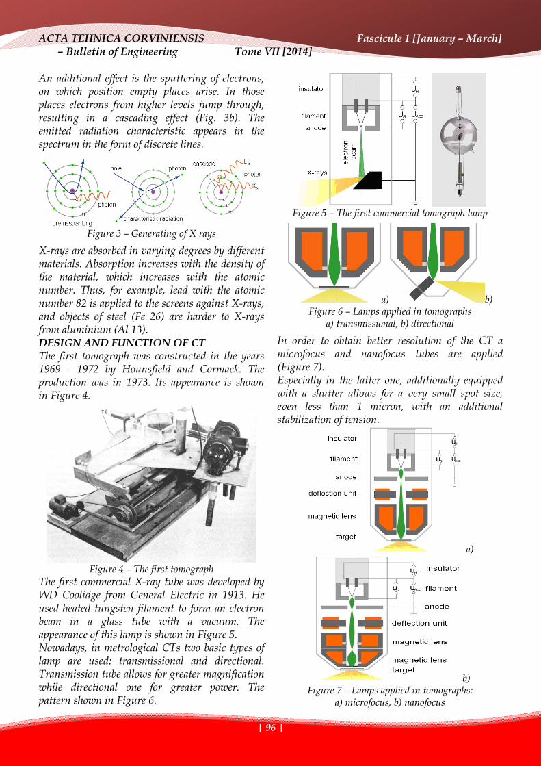
An additional effect is the sputtering of electrons, on which position empty places arise. In those places electrons from higher levels jump through, resulting in a cascading effect (Fig. 3b). The emitted radiation characteristic appears in the spectrum in the form of discrete lines.
Figure 3 – Generating of X rays
X-rays are absorbed in varying degrees by different materials. Absorption increases with the density of the material, which increases with the atomic number. Thus, for example, lead with the atomic number 82 is applied to the screens against X-rays, and objects of steel (Fe 26) are harder to X-rays from aluminium (Al 13). DESIGN AND FUNCTION OF CT The first tomograph was constructed in the years 1969 - 1972 by Hounsfield and Cormack. The production was in 1973. Its appearance is shown in Figure 4.
Figure 4 – The first tomograph
The first commercial X-ray tube was developed by WD Coolidge from General Electric in 1913. He used heated tungsten filament to form an electron beam in a glass tube with a vacuum. The appearance of this lamp is shown in Figure 5. Nowadays, in metrological CTs two basic types of lamp are used: transmissional and directional. Transmission tube allows for greater magnification while directional one for greater power. The pattern shown in Figure 6.
Figure 5 – The first commercial tomograph lamp
a) b) Figure 6 – Lamps applied in tomographs
a) transmissional, b) directional
In order to obtain better resolution of the CT a microfocus and nanofocus tubes are applied (Figure 7). Especially in the latter one, additionally equipped with a shutter allows for a very small spot size, even less than 1 micron, with an additional stabilization of tension.
a)
b) Figure 7 – Lamps applied in tomographs:
a) microfocus, b) nanofocus

ACTA TEHNICA CORVINIENSIS Fascicule 1 [January – March] – Bulletin of Engineering Tome VII [2014]
| 97 |
The CT can be constructed in 2D and 3D version. 2D CT is known as a flat beam CT (Fig. 8a), while 3D ones as cone beam CT (Fig. 8b).
a)
b) Figure 8 – Tomograph:
a) with cone beam, b) with fan beam.
Another important element of CT is the detector, which is the system that presents the resulting image. Firstly, X-rays are converted to visible light by a film or scintillation crystal. Then this visible light is received by photodiodes, making possible presentation of the image. Schematic layout of the detector is shown in Figure 9.
Figure 9 – Detector in CT
IMAGE ANALYSIS The next step after collecting the images is reconstruction of the whole element [9, 11]. It takes place in space, considered as a three-dimensional array of voxels. By definition voxel (called volumetric element - similar to the pixel) is the smallest element of the 3D space, the equivalent of a pixel in 2D (Fig. 10).
Figure 10 – Graphical presentation of voxel
The accuracy of the reconstruction is affected substantially by the size of the voxel V and the spot size at the focal point F (Fig. 11a), which is the limit of resolution [4]. In addition, there are relations between: V = P / M, M = FDD / FOD, where P – pixel, M – zoom. ROI is the area of observation (Fig. 11b).
a)
b) Figure 11 – Image analysis: a) area of observation, b)
size of the spot and zoom
ACTA TEHNICA CORVINIENSIS Fascicule 1 [January – March] – Bulletin of Engineering Tome VII [2014]
| 98 |
Geometric zoom is therefore dependent on the distance between the lamp and the object, as shown in Figure 12. Image sharpness depends on the size of the focal spot as presented in Figure 13.
Figure 12 – Following steps of the image zoom
Figure 13 – Following steps of obtaining sharp view
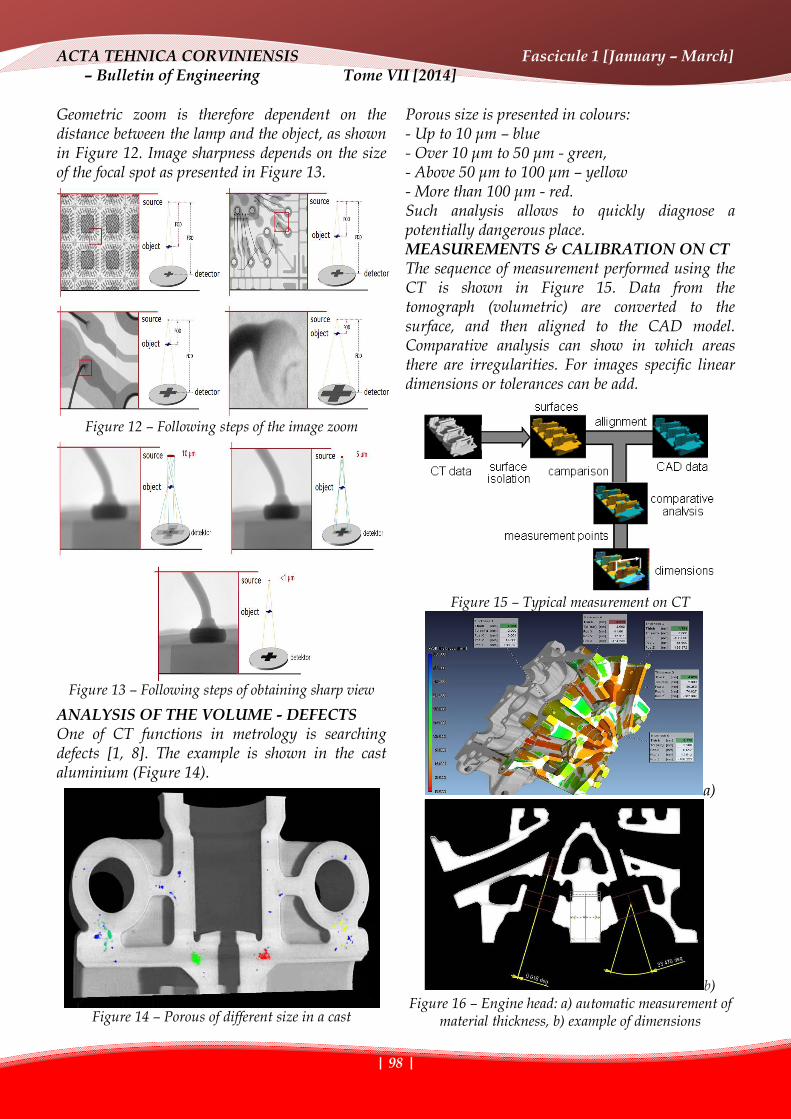
ANALYSIS OF THE VOLUME - DEFECTS One of CT functions in metrology is searching defects [1, 8]. The example is shown in the cast aluminium (Figure 14).
Figure 14 – Porous of different size in a cast
Porous size is presented in colours: - Up to 10 μm – blue - Over 10 μm to 50 μm - green, - Above 50 μm to 100 μm – yellow - More than 100 μm - red. Such analysis allows to quickly diagnose a potentially dangerous place. MEASUREMENTS & CALIBRATION ON CT The sequence of measurement performed using the CT is shown in Figure 15. Data from the tomograph (volumetric) are converted to the surface, and then aligned to the CAD model. Comparative analysis can show in which areas there are irregularities. For images specific linear dimensions or tolerances can be add.
Figure 15 – Typical measurement on CT
a)
b) Figure 16 – Engine head: a) automatic measurement of
material thickness, b) example of dimensions

ACTA TEHNICA CORVINIENSIS Fascicule 1 [January – March] – Bulletin of Engineering Tome VII [2014]
| 99 |
Figure 16a presents an example of automatic measurement of the thickness of 3 - cylinder engine head. Using the finished image data, solid of geometric figures can be entered and, on this basis, measurement of distances, angles, radius etc. can be conducted. Analyzing tomographic measurement accuracy, the guide VDI / VDE 2630 (in preparation) connect the procedure to the standard ISO 10360. It defines specific permissible errors for CT in metrology. Length measurement error ESD = Lm-Lr is expressed as the difference between the measured value and the nominal one, for the item shown in Figure 17.
a)
b) Figure 17 – Diagram of length measurement error (a)
and the pattern (b) The pattern consists of two ruby balls connected with the rod made of carbon fibres. The calibration was performed on the coordinate measuring machine with high accuracy, for example, the uncertainty UCMM = ± 0.5 μm for length under 100mm. Other maximum permissible errors are the error of probing form PF = Rmax - Rmin shown in Figure 18a and measurement error of probing size PS = Da - Dr. (the difference of the measured and nominal diameter) to denote the location of the surface (Fig. 18b).
a) b) Figure 18 – Diagram of determining form probing error (a) and size probing error (b)
According to VDI / VDE 2630 modern CT achieve the level of uncertainty in the PS = 1.5 + L/300 [µm], where L is given in mm. Examples of systems are shown in Figure 19.
Figure 19 – Examples of CT
(producer GE / Phoenix x-ray) SUMMARY Computed tomography is a new measuring technique, entering the length and angle metrology. For visible surface, it aspires to be compared to coordinate measurement technique. For hidden part of the element it is a unique technique that enables all reliable measurement data collection and performance measurement. X-ray tomography enable measurement of various materials, including plastics, aluminium and steel. Considering measuring possibilities and parameters of the hardware the most important aspect is adequate generation and detection of X-ray CT. The value of maximum measurement error of CT determined according to guide which is in preparation is about single microns. REFERENCES [1] Banhart, J.: Advanced Tomographic Methods in
Materials Research and Engineering, Oxford University Press, 2008.
[2] Bushong, S.: Computed Tomography, McGraw-Hill, 2000.
[3] Buzug, T. M.: Computed Tomography: From Photon Statistics to Modern Cone-Beam CT, Springer, 2008.
[4] Gardner, R. J.: Geometric Tomography, Cambridge University Press, 2006.
[5] Grangeat, P.: Tomography, Wiley-ISTE, 2009.
ACTA TEHNICA CORVINIENSIS Fascicule 1 [January – March] – Bulletin of Engineering Tome VII [2014]
| 100 |
[6] Herman G. T.: Fundamentals of Computerized Tomography: Image Reconstruction from Projections, Springer, 2009.
[7] Kalender, W. A.: Computed Tomography: Fundamentals, System Technology, Image Quality, Applications, Wiley-VCH, 2006.
[8] Maire, E., Merle, P., Peix, G., Baruchel, J., Buffiere, J.-Y.: X-Ray Tomography in Material Science, Hermes Science Publications, 2000.
[9] Ramm, A. G.: Inverse Problems, Tomography and Image Processing, Springer, 1998.
[10] Romans L. E.: Introduction to Computed Tomography, Lippincott Williams & Wilkins, 1995.
[11] Sorokin, N.: High-Performance Reconstruction in Computer Tomography: Formal Specification and Implementation, VDM Verlag, 2008.
[12] Vogl, T. J., Clauss, W., Li, G.Z., Yeo,n K.M.: Computed Tomography: State of the Art and Future Applications, Springer-Verlag Telos, 1996.
copyright ©
University “POLITEHNICA” Timisoara, Faculty of Engineering Hunedoara,
5, Revolutiei, 331128, Hunedoara, ROMANIA
http://acta.fih.upt.ro