x box 360 controller cleaning v11 - rick.sparber.orgrick.sparber.org/csix.pdf · once the back...
TRANSCRIPT

R. G. Sparber November 27, 2016 Page 1 of 20
Cleaning a Swarf Invaded X Box 360
Controller, version 1.1
By R. G. Sparber
Protected by Creative Commons.1
This Genuine Microsoft X Box 360 Controller
is my favorite means of controlling my Mach3
CNC Program and RF-30 Mill/Drill. The joy
sticks let me manually adjust the X, Y, Z, and A
axes plus zero any of their Digital Read Outs2.
Over the last few months, Mach3 has randomly
frozen when I was moving the various axes via
this controller. No problem when movement
was controlled by the keyboard.
After spending a lot of time trying to eliminate the software as the possible source
of the fault, I turned to the hardware. I opened up the case and was greeted with
many tiny flecks of aluminum (called swarf) that came from the machining
process. It amazes me how so much metal could get inside this controller.
This article explains how I cleaned the controller and reassembled it.
Here is an overriding fact if you are worried about taking this device apart and not
getting it back together: Extremely low skilled people assemble these controllers.
Every single part, with one minor exception, are keyed to only go in one place. If a
part does not fit, you either have the wrong part or it is not oriented correctly.
If you prefer to follow a video for reassembly, go to YouTube.com and search
using "X Box 360 Controller". There are many videos although I found
"MyCustom Xbox" to be the best.
1 This work is licensed under the Creative Commons Attribution 4.0 International License. To view a copy of this
license, visit http://creativecommons.org/licenses/by/4.0/ or send a letter to Creative Commons, PO Box 1866,
Mountain View, CA 94042, USA. 2 See http://rick.sparber.org/CNCHW.pdf
R. G. Sparber November 27, 2016 Page 2 of 20
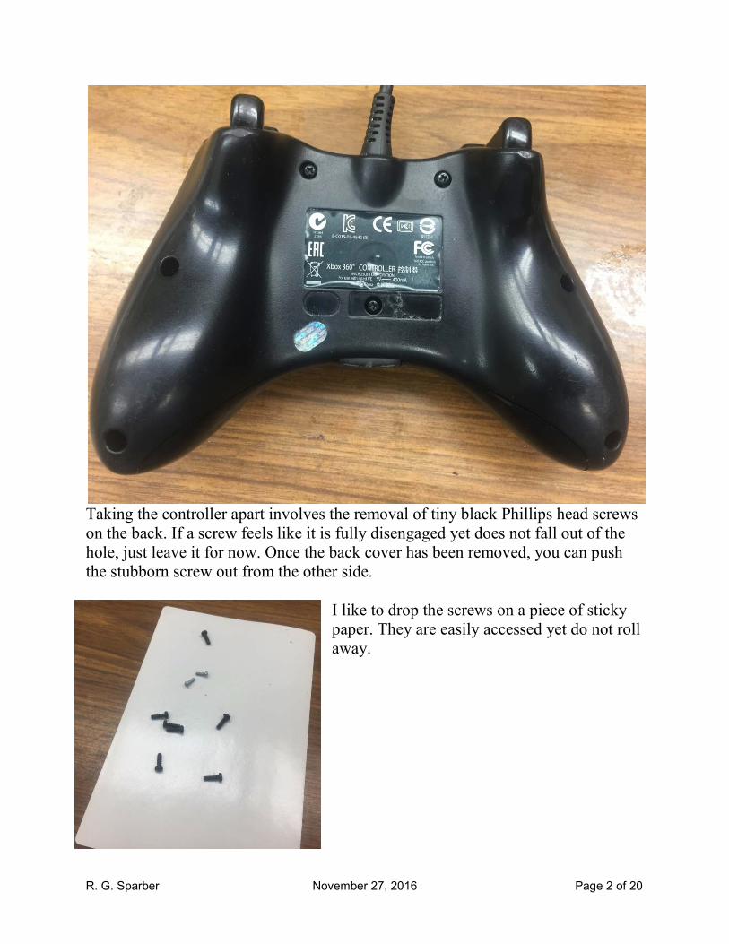
Taking the controller apart involves the removal of tiny black Phillips head screws
on the back. If a screw feels like it is fully disengaged yet does not fall out of the
hole, just leave it for now. Once the back cover has been removed, you can push
the stubborn screw out from the other side.
I like to drop the screws on a piece of sticky
paper. They are easily accessed yet do not roll
away.

R. G. Sparber November 27, 2016 Page 3 of 20
The back cover should then just lift off. Dump all plastic parts into a clean
container. No reason to record where parts go with one exception: two motors are
driven from the circuit board. One motor has a large weight on it and the other has
a small weight. Their plugs are not keyed.

R. G. Sparber November 27, 2016 Page 4 of 20
You will find the control pad (white
arrow) does not fall out. Look closely on
the inside of this pad and you will find two
screws to remove.
Then you will find two
tabs (yellow arrows)
that must be gently
moved to release the
two disks.

R. G. Sparber November 27, 2016 Page 5 of 20
Here is the top side of the circuit board. You can lightly spray the surface with
alcohol and carefully blot it clean. I use toilet paper to do the blotting. Care was
taken to not take a contaminated part of the paper and touch the board. After
cleaning, I used a magnifier to verify all swarf had been removed.

R. G. Sparber November 27, 2016 Page 6 of 20
Then I cleaned the other side of the board.
All of the remaining parts are plastic. I went into my kitchen and carefully cleaned
and rinsed the sink. Then I filled the sink with about two inches of hot, soapy
water. In went all of the plastic parts.
One at a time I removed the parts, rinsed them, shook off excess water, and
inspected with my magnifier for any bits of swarf. Then I used a clean paper towel
to remove any remaining water.
Any swarf left on plastic parts will inevitably migrate onto the circuit board.
R. G. Sparber November 27, 2016 Page 7 of 20
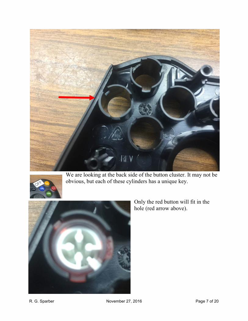
We are looking at the back side of the button cluster. It may not be
obvious, but each of these cylinders has a unique key.
Only the red button will fit in the
hole (red arrow above).

R. G. Sparber November 27, 2016 Page 8 of 20
Using the color and the mechanical keying, it
didn't take long to get the correct button in each
hole. Note that I relabeled the red button with the
letter "Z". All other buttons are stock.

R. G. Sparber November 27, 2016 Page 9 of 20
Find the green cylinder and the clear cylinder
with the black feature on one end. These are
assembled to become the status light (green
arrow).
The two parts are keyed. Do not force them together.
Drop the assembly into the
hole.

R. G. Sparber November 27, 2016 Page 10 of 20
Locate these two
parts.
Identify this recess in the top cover.

R. G. Sparber November 27, 2016 Page 11 of 20
Fit the larger part into this hole and rotate until the key permits it to drop in.
Holding it in place, turn the cover
over so you see this. Snap in the
smaller part.
Then flip the cover over again.

R. G. Sparber November 27, 2016 Page 12 of 20
The following procedure insures that the self tapping screws go back into the
original threads. Failure to do this can cause new threads to be cut. The result
will be screw threads that can more easily strip out.
Drop in the first screw. Start by turning it counterclockwise (as if you were
unscrewing it) until you feel it go in slightly. This is the opening of the previously
cut thread. Then gently tighten clockwise so it is part way down. Repeat for the
second screw. Verify the assembly freely moves. Then snug down both screws.

R. G. Sparber November 27, 2016 Page 13 of 20
Locate the two flanking button holes (red arrows).
Then find the two black buttons. These two buttons are identical
but drop into the two holes with opposite orientation.

R. G. Sparber November 27, 2016 Page 14 of 20
Next, locate this curved piece.
It fits over posts molded into the top cover.

R. G. Sparber November 27, 2016 Page 15 of 20
Locate the remaining curved part.
It fits over pegs molded into the top cover.

R. G. Sparber November 27, 2016 Page 16 of 20
Locate the gray floppy disk. Position it with the dark gray dots facing you as
shown here.
The disk fits over the right hole with the tab fitting over the post (red arrow).

R. G. Sparber November 27, 2016 Page 17 of 20
The second floppy light gray part goes over the various buttons.
The dark grey dots face towards you. As with everything else, it is keyed so can
only go on one way.

R. G. Sparber November 27, 2016 Page 18 of 20
Place the circuit board down on the top cover. It will drop into place over the
molded posts. The two motors fit in curved pockets. Note that the USB control
cable has a molded strain relief. The rectangular section of this molding fits
downward.
Notice the two trigger switches (red arrows). The back cover must fit around these
triggers.
R. G. Sparber November 27, 2016 Page 19 of 20
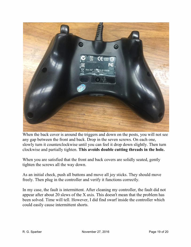
When the back cover is around the triggers and down on the posts, you will not see
any gap between the front and back. Drop in the seven screws. On each one,
slowly turn it counterclockwise until you can feel it drop down slightly. Then turn
clockwise and partially tighten. This avoids double cutting threads in the hole.
When you are satisfied that the front and back covers are solidly seated, gently
tighten the screws all the way down.
As an initial check, push all buttons and move all joy sticks. They should move
freely. Then plug in the controller and verify it functions correctly.
In my case, the fault is intermittent. After cleaning my controller, the fault did not
appear after about 20 slews of the X axis. This doesn't mean that the problem has
been solved. Time will tell. However, I did find swarf inside the controller which
could easily cause intermittent shorts.
R. G. Sparber November 27, 2016 Page 20 of 20
Thanks to Leon Robinson for suggesting how to avoid having the self tapping
screw double cutting threads.
I welcome your comments and questions.
If you wish to be contacted each time I publish an article, email me with just
"Article Alias" in the subject line.
Rick Sparber
Rick.Sparber.org