wyzbee - mouser.de · page 9 wyz ee™ user manual version 1.2 2 setting up wyz ee™ 2.1 setup...
TRANSCRIPT

WyzBee™
User Manual
Version 1.2
October 2015
Redpine Signals, Inc. 2107 N. First Street, #680
San Jose, CA95131. Tel: (408) 748-3385 Fax: (408) 705-2019
Email: [email protected]
Website: www.redpinesignals.com
Redpine Signals, Inc. 2107 N. First Street, #680
San Jose, CA95131. Tel: (408) 748-3385 Fax: (408) 705-2019
Email: [email protected]
Website: www.redpinesignals.com

Page 2
WyzBee™ User Manual Version 1.2
WyzBee™ User Manual Version 1.2
About this Document This document describes general information of WyzBee™ along with the board bring up and installation procedure for software tools for developing applications, including a sample TriLED demo programmed using Keil IDE platform. This document elaborates all the features and steps for using the WyzBee™ platform.
Disclaimer: The information in this document pertains to information related to Redpine Signals, Inc. products. This information is provided as a service to our customers, and may be used for information purposes only. Redpine assumes no liabilities or responsibilities for errors or omissions in this document. This document may be changed at any time at Redpine’s sole discretion without any prior notice to anyone. Redpine is not committed to updating this document in the future.
Copyright © 2015 Redpine Signals, Inc. All rights reserved.

Page 3
WyzBee™ User Manual Version 1.2
WyzBee™ User Manual Version 1.2
Table of Contents
1 Introduction ......................................................................................................... 5
1.1 Features ........................................................................................................................ 5 1.1.1 MCU Features ..........................................................................................................................5 1.1.2 WLAN Features ........................................................................................................................6 1.1.3 Bluetooth .................................................................................................................................6 1.1.4 ZigBee ......................................................................................................................................6 1.1.5 General ....................................................................................................................................6
1.2 WyzBee™ Board............................................................................................................ 7 1.3 WyzBee™ Top View ...................................................................................................... 8 1.4 WyzBee™ Bottom View ................................................................................................ 8
2 Setting up WyzBee™ ............................................................................................. 9 2.1 Setup Requirements ..................................................................................................... 9 2.2 Installing the CMSIS-DAP Drivers .................................................................................. 9 2.3 Installing IDEs ............................................................................................................. 10
3 Getting Started ................................................................................................... 11
3.1 Starting a New Project ................................................................................................ 11 3.2 Configuring IDE for WyzBee™ ..................................................................................... 11 3.3 Sample Project............................................................................................................ 15 3.4 Adding THINGS ........................................................................................................... 17
4 Appendix A: Installing IDEs ................................................................................. 18
4.1 Keil IDE ....................................................................................................................... 18 4.1.1 Download and Installation .....................................................................................................18 4.1.2 Configuring Keil IDE for WyzBee™ .........................................................................................21
4.2 CoIDE .......................................................................................................................... 21 4.2.1 Download and Installation .....................................................................................................22 4.2.2 Configuring CoIDE for WyzBee™............................................................................................24
4.3 IAR Embedded Workbench ......................................................................................... 27 4.3.1 Download and Installation .....................................................................................................27 4.3.2 Configuration IAR Embedded Workbench for WyzBee™ ......................................................35
5 Appendix B: WyzBee™ Headers........................................................................... 37
5.1 Pin Description ........................................................................................................... 37
Table of Figures Figure 1: WyzBee™ Baseboard with micro-B USB Cable ...............................................................................7 Figure 2: WyzBee™ Baseboard’s Top View ....................................................................................................8 Figure 3: WyzBee™ Baseboard’s Bottom View ..............................................................................................8 Figure 4: CMSID-DAP Drivers Installation Window........................................................................................9 Figure 5: WyzBee™ CMSIS-DAP Debug Port Detection................................................................................10 Figure 6: Keil uVision: Selecting the Device .................................................................................................11 Figure 7: Keil uVision: Options for Target – Utilities ....................................................................................12 Figure 8: Keil uVision: CMSIS-DAP Debugger Settings .................................................................................12 Figure 9: Keil uVision: Options for Target – Debug ......................................................................................13 Figure 10: Keil uVision: Options for Target – Debug ....................................................................................13 Figure 11: Keil uVision: Options for Target – Target ....................................................................................14 Figure 12: Keil uVision: Options for Target – Output ...................................................................................14

Page 4
WyzBee™ User Manual Version 1.2
WyzBee™ User Manual Version 1.2
Figure 13: Keil uVision: Options for Target – Linker ....................................................................................15 Figure 14: main.c of TriLED Project in Keil uVision4 ....................................................................................16 Figure 15: TriLED_App Function ...................................................................................................................16 Figure 16: Debug Cursor at main Function ...................................................................................................17 Figure 17: Keil IDE Installation Window .......................................................................................................18 Figure 18: Keil IDE Installation License Agreement .....................................................................................19 Figure 19: Keil IDE Installation Folder Selection ..........................................................................................19 Figure 20: Keil IDE Customer Information ....................................................................................................20 Figure 21: Keil IDE Installation Completed ...................................................................................................20 Figure 22: Keil IDE Installation Completed ...................................................................................................21 Figure 23: ULINK Driver Installation .............................................................................................................21 Figure 24: CoIDE Installation Window ..........................................................................................................22 Figure 25: CoIDE Installation Folder Selection .............................................................................................23 Figure 26: CoIDE Installation Start................................................................................................................23 Figure 27: GCC Toolchain Path for CoIDE .....................................................................................................24 Figure 28: CoIDE Version...............................................................................................................................24 Figure 28: CoIDE Configuration Button ........................................................................................................24 Figure 29: CoIDE Configuration – Device ......................................................................................................25 Figure 30: CoIDE Configuration – Link ..........................................................................................................25 Figure 31: CoIDE Configuration – Output .....................................................................................................26 Figure 32: CoIDE Configuration – User .........................................................................................................26 Figure 33: CoIDE Configuration – Debugger .................................................................................................26 Figure 34: CoIDE Configuration – Download ................................................................................................27 Figure 35: IAR Embedded Workbench Installation Window .......................................................................28 Figure 36: IAR Embedded Workbench Installation Window .......................................................................28 Figure 37: IAR Embedded Workbench License Agreement .........................................................................29 Figure 38: IAR Embedded Workbench Installation Folder...........................................................................29 Figure 39: IAR Embedded Workbench Installation Start .............................................................................30 Figure 40: IAR Embedded Workbench – Dongle Drivers Installation ..........................................................30 Figure 41: IAR Embedded Workbench Installation Completed ...................................................................31 Figure 42: IAR Embedded Workbench – Device Software – 1 .....................................................................31 Figure 43: IAR Embedded Workbench – Device Software – 2 .....................................................................32 Figure 44: IAR Embedded Workbench – Language Selection ......................................................................32 Figure 45: IAR Embedded Workbench – License Wizard .............................................................................32 Figure 46: IAR Embedded Workbench – License Wizard (Choose a Product) .............................................33 Figure 47: IAR Embedded Workbench – License Wizard (Register) ............................................................33 Figure 48: IAR Embedded Workbench: Registration ...................................................................................34 Figure 49: IAR Embedded Workbench: Registration Complete...................................................................35 Figure 50: IAR Embedded Workbench – Project Options ............................................................................35 Figure 51: IAR Embedded Workbench – Options – 1 ...................................................................................36 Figure 52: IAR Embedded Workbench – Options – 2 ...................................................................................36 Figure 53: 32-pin WyzBee™ THING Header ..................................................................................................37
Table of Tables Table 1: TriLED Connections to MCU ............................................................................................................15

Page 5
WyzBee™ User Manual Version 1.2
WyzBee™ User Manual Version 1.2
1 Introduction
The WyzBee™IoT platform is an industry-first single source offering with fully inclusive sensing, computing, communicating, and cloud support. The compact WyzBee™ board includes Redpine’s Wireless Secure MCU (WiSeMCU™) with multi-protocol wireless module providing Wi-Fi, Bluetooth 4.1, and ZigBee connectivity, nine-axis inertial sensors, onboard temperature/humidity sensors, 3 axis accelerometer , an infrared receiver, a USB (debug) port, push-buttons, LEDs, and WyzBee™ THING™ expansion connector. The WiSeMCU module runs an embedded TCP/IP networking stack with SSL/TLS/HTTPS security, apart from complete Wi-Fi, BT 4.1, and ZigBee stacks.
The WyzBee™ THING expansion headers accommodate a host of other symbiotic devices, with a number of peripherals – called ‘THINGS’ – already available from Redpine including audio, GSM, GPS, capacitive touch display, rechargeable battery, and additional sensors. Application development is supported with a choice of development environments – IAR, Keil, and the free CoIDE from CooCox.
The WiSeMCU™ module integrates PUF-based hardware security block that provides for unique, individual device entities – ensuring that each IoT device can be individually authenticated and software delivered to it that cannot run on any other device.
1.1 Features
1.1.1 MCU Features
ARM Cortex-M4F processor, running at a frequency of up to 160 MHz
Integrated Floating Point Unit (FPU), Memory Protection Unit (MPU), Built-in Nested Vectored Interrupt Controller (NVIC)
Debug options: JTAG and Embedded Trace Macrocells (ETM)
1MB on-chip flash program memory with flash accelerator and 32KB work flash memory
128 KB SRAM for code and data use
CAN Interface with support for up to 2 channels
Up to 32 high speed general purpose I/O ports.
Multi-function Serial Interface with support for up to 6 channels (UART, CSIO (SPI), and I2C).
Base timer (maximum 8 channels) supporting PWM, PPG, reload timer, PWC (up to 6 channels).
Comprehensive Timers: Multi-function timer (MFT) with FRT, WFG, ICU, OCU modes supported.
RTC, QPRC, Dual Timer supported.
Up to 2 configurable Watchdog Timers.
Analog peripherals: 12-bit, 11-channel Analog-to-Digital Converter (ADC)
Security: Unique ID of the device (41 bit) is set
Six low-power consumption modes: SLEEP, Timer, RTC, STOP, Deep Standby RTC, Deep Standby stop.

Page 6
WyzBee™ User Manual Version 1.2
WyzBee™ User Manual Version 1.2
12-bit Digital to Analog Converter (DAC) with support for 1 channel
DMA Controller with support for up to 8 channels
CRC (Cyclic Redundancy Check) Accelerator
External interrupt input pins: up to 14 pins
Low-Voltage Detector (LVD) current: 100nA
CMSIS-DAP Debug adapter: WyzBee™ comes with an on board CMSIS-DAP debug adapter for downloading and debugging applications, without the need for an external debugger.
1.1.2 WLAN Features
Compliant to single-spatial steam IEEE 802.11 a/b/g/n with dual band (2.4 and 5 GHz) support.
Support for 20MHz channel bandwidth.
Transmit power up to +18dBm with integrated PA.
Receive sensitivity of -97dBm.
Supports Wi-Fi Direct™, Access point mode, WPA/WPA2-PSK, WPA/WPA2-Enterprise (EAP-TLS, EAP-FAST, EAP-TTLS, PEAP-MS-CHAP-V2).
1.1.3 Bluetooth
Compliant to dual-mode Bluetooth 4.0.
Transmit power up to 15dBm (class-1) with integrated PA.
Receive sensitivity of -94 dBm.
Basic Bluetooth profile embedded in device.
1.1.4 ZigBee
Compliant to IEEE 802.15.4
Transmit power up to 15 dBm with integrated PA.
Receive sensitivity of -102 dBm.
ZigBee Pro stack embedded
1.1.5 General
U.FL connector for external antenna connection.
Operating temperature range: -40oC to +85
oC
TCP/IP stack (IPv4/IPv6), HTTP/HTTPS, DHCP, ICMP, SSL 3.0/TLS1.2, Web sockets, IGMP, FTP Client, SNTP, DNS, embedded in the device.
On Board Peripherals:
o Tri Color LED
LED Color Pin
Red P41

Page 7
WyzBee™ User Manual Version 1.2
WyzBee™ User Manual Version 1.2
Blue P3F
Green P3E
o Two push buttons (One for Reset and one for an External interrupt)
Push Button Pin
SW1(External Interrupt) P50
SW2 (Reset) MCU_RESET_N
o IR receiver
IR Receiver Pin
IR_OUT P42
o 9 Axis Sensor
o 3 Axis Accelerometer
o Humidity and Temperature Sensor
Sensor Pin
All three sensors use the I2C interface to interact with the MCU.
Clock P33
Data P32
o Micro-B USB Full Speed Interface
1.2 WyzBee™ Board
WyzBee™ is a USB-powered device. Shown below is a WyzBee™ baseboard with the micro-B USB cable plugged in.
Figure 1: WyzBee™ Baseboard with micro-B USB Cable

Page 8
WyzBee™ User Manual Version 1.2
WyzBee™ User Manual Version 1.2
1.3 WyzBee™ Top View
Figure 2: WyzBee™ Baseboard’s Top View
1.4 WyzBee™ Bottom View
Figure 3: WyzBee™ Baseboard’s Bottom View

Page 9
WyzBee™ User Manual Version 1.2
WyzBee™ User Manual Version 1.2
2 Setting up WyzBee™
2.1 Setup Requirements
Setting up and working with WyzBee™ is easy. Before you start, make sure you have the following hardware and software components:
Hardware:
The WyzBee™ baseboard 32/64-bit PC with minimum 2GB RAM and USB Port for Power, Downloading and
Debugging Software:
Windows 7/8/8.1 Operating System.
The CMSIS-DAP driver provided by Spansion. You can download the driver from https://www.spansion.com/Support/microcontrollers/developmentenvironment/Pages/board-SK-FM4-U120-9B560.aspx. More details are given in Section 2.2.
An IDE like Keil uVision, IAR Embedded Workbench or CooCox CoIDE.
2.2 Installing the CMSIS-DAP Drivers
Follow the steps below to download and install the CMSIS-DAP Drivers.
1) Download the complete set of drivers and tools from the following link:
(USB drivers for virtual COM port and CMSIS-DAP)
https://www.spansion.com/Support/microcontrollers/developmentenvironment/Pages/board-SK-FM4-U120-9B560.aspx
Note: If the device gets detected as an unknown device, update the drivers from the device
manager and point to the location of the newly downloaded drivers.
2) Windows USB drivers that are specific to WyzBee™ need to be installed for the detection of debugging port. In the downloaded folder, navigate to the “drivers” folder and double-click on the driverinstaller.exe file. The window below will appear.
Figure 4: CMSID-DAP Drivers Installation Window

Page 10
WyzBee™ User Manual Version 1.2
WyzBee™ User Manual Version 1.2
3) Click the Next button.
4) A “Publisher cannot be verified”, warning might appear depending on the Windows Security Settings. Select the “Install this driver software anyway” option. This installs the cmsis-dap and usbdirect drivers.
5) Click the Finish button after the drivers’ installation is completed.
6) Connect the micro-B USB cable between the WyzBee™ USB port and the PC. Verify that the board is detected under the “Ports” section of the Windows Device Manager.
Figure 5: WyzBee™ CMSIS-DAP Debug Port Detection
2.3 Installing IDEs
WyzBee™ applications can be developed using various IDEs like CoIDE, Keil and IAR. Refer to Appendix A for instructions on downloading and installing these tools..

Page 11
WyzBee™ User Manual Version 1.2
WyzBee™ User Manual Version 1.2
3 Getting Started
This section helps in getting started quickly with WyzBee™. It describes the process for starting a project, configuring the IDE for WyzBee™ and then working with an example project.
It is necessary to know your way around one of the supported IDE’s in order to work on WyzBee™. The steps below use the Keil uVision 4 IDE as an example to download and debug a sample application on WyzBee™.
3.1 Starting a New Project
1) Start the Keil uVision 4 IDE.
2) Click on “New uVision Project” from the “Project” dropdown menu. A popup window appears giving you an option to select the location of the project. Select the path you would like and click “Save”.
3) A new window opens for selecting the device. Scroll down the list and select “MB9BF568N” as shown below.
Figure 6: Keil uVision: Selecting the Device
4) Click OK and you are now ready to start configuring the IDE for WyzBee™.
3.2 Configuring IDE for WyzBee™
The Keil IDE is used here as an example. The process for CoIDE and IAR Embedded Workbench is explained in Appendix A.

Page 12
WyzBee™ User Manual Version 1.2
WyzBee™ User Manual Version 1.2
1) In the Keil uVision IDE window, click on “Options for Target”.
2) In the new window that opens, click on the “Utilities” tab. Uncheck the “Use Debug Driver” option.
3) Next, in the dropdown menu for “Use Target Driver for Flash Programming”, select “CMSIS-DAP Debugger” and click “Settings”.
Figure 7: Keil uVision: Options for Target – Utilities
4) In the popup window, click “Add” and select the device name highlighted in the image below. Click OK.
Figure 8: Keil uVision: CMSIS-DAP Debugger Settings

Page 13
WyzBee™ User Manual Version 1.2
WyzBee™ User Manual Version 1.2
5) Next, click the “Debug” tab and select “Use” and “CMSIS-DAP Debugger” as shown below.
Figure 9: Keil uVision: Options for Target – Debug
6) Click on the “Device” tab and ensure that the settings are as shown in the image below.
Figure 10: Keil uVision: Options for Target – Debug
7) Click on the “Target” tab and ensure all settings are as shown in the image below.

Page 14
WyzBee™ User Manual Version 1.2
WyzBee™ User Manual Version 1.2
Figure 11: Keil uVision: Options for Target – Target
8) Click on the “Output” tab and ensure all settings are as shown in the image below.
Figure 12: Keil uVision: Options for Target – Output
9) Click on the “Linker” tab and ensure all settings are as shown in the image below.

Page 15
WyzBee™ User Manual Version 1.2
WyzBee™ User Manual Version 1.2
Figure 13: Keil uVision: Options for Target – Linker
The IDE is now configured for WyzBee™. You can now start writing your application!
3.3 Sample Project
A sample project, TriLED.zip, which blinks the onboard TriLED is provided to help you quickly get started on WyzBee™. The details of the pins of the MCU connected to the TriLED are given below:
LED Color MCU Pin
Red P41
Green P3E
Blue P3F
Table 1: TriLED Connections to MCU
The project, when run, blinks the LEDs one at a time with a certain delay. Follow the steps below to compile, flash and run the example project.
1) Download the blinky project (TriLED.zip) from the URL above and extract it.
2) Double-click the Keil uVision4 project file.This opens the Keil IDE.
$(Extracted_Folder)\ TriLed\IDE\Keil\ TriLed.uvproj
3) Open main.c in the IDE from the Project menu, as shown in the image below.

Page 16
WyzBee™ User Manual Version 1.2
WyzBee™ User Manual Version 1.2
Figure 14: main.c of TriLED Project in Keil uVision4
4) The TriLED_App() function controls all the frontend functioning of the application. It initializes the necessary drivers and configures WyzBee™. The source code is shown in the image below.
Figure 15: TriLED_App Function
5) TriLED_App() Function:
a. The TriLEDGpio_Put function is used to change the value assigned to the pins. GPIO_LOW indicates LED On and GPIO_HIGH indicates LED Off.

Page 17
WyzBee™ User Manual Version 1.2
WyzBee™ User Manual Version 1.2
6) Configure Keil for WyzBee™ as explained in Section 3.2.
7) Compile the project by clicking on Project Build Target.
8) After successful compilation, click on Flash Erase to Erase the MCU’s Flash contents.
9) Next, click on Debug Start/Stop Debug Session to download the application to the MCU. The IDE now shows the debug cursor pointing to the main function in the main.c file.
Figure 16: Debug Cursor at main Function
10) Use the Run (Ctrl+F5), Step-in (F11), Step-out (F10) and Step-over (Ctrl+F11) options to execute and debug the application.
For more details on how to use Keil uVision4 IDE, refer the document from the following link:
http://www.keil.com/product/brochures/uv4.pdf
You can now start writing your own Application using the API libraries provided. The APIs are explained in WyzBee API Guide document.
3.4 Adding THINGS
The WyzBee™ THING expansion headers accommodate a host of other symbiotic devices, with a number of peripherals – called ‘Things’ – already available from Redpine including audio, GSM, GPS, capacitive touch display, rechargeable battery, and additional sensors.
Adding THINGs is as simple as stacking one board on top of the other. Care needs to be taken to ensure that the interfaces being used for one THING are not being used by another THING when stacking multiple THINGs.
Details on the THINGs are available in their individual documents.

Page 18
WyzBee™ User Manual Version 1.2
WyzBee™ User Manual Version 1.2
4 Appendix A: Installing IDEs
This section describes the steps for downloading and installing the IDEs1 which can be used with WyzBee™.
4.1 Keil IDE
The Keil IDE from ARM can be used for IoT application development and supports both C and C++ languages.
4.1.1 Download and Installation
Evaluation version of Keil IDE can be downloaded from https://www.keil.com.The following steps have been described for Keil version 4.7.4.
We strongly recommend ensuring you are downloading the MDK-ARM V4.74 setup file.
You need to register yourself to generate the setup file to be downloaded.
1) Start the installer. If any security warnings appear, click on Run.
2) In the Installer window, click Next.
3) Click Next again to continue the installation.
Figure 17: Keil IDE Installation Window
4) Check the “I agree to all the terms…” option and click Next.
1 Keil and IAR impose a code size limitation of 32KB on the evaluation versions of their IDEs

Page 19
WyzBee™ User Manual Version 1.2
WyzBee™ User Manual Version 1.2
Figure 18: Keil IDE Installation License Agreement
5) In the next window, you have the option of changing the folder in which the IDE will be installed. Change it if required and click Next.
Figure 19: Keil IDE Installation Folder Selection
6) Enter your details in the next window and click Next to start the installation process.

Page 20
WyzBee™ User Manual Version 1.2
WyzBee™ User Manual Version 1.2
Figure 20: Keil IDE Customer Information
7) After the installation is completed, click Next again.
Figure 21: Keil IDE Installation Completed
8) Now, select the “Launch Driver Installation: ULINK Pro Driver V1.0” option and click Finish.

Page 21
WyzBee™ User Manual Version 1.2
WyzBee™ User Manual Version 1.2
Figure 22: Keil IDE Installation Completed
9) In the new window that opens, click Install to continue with the installation of the ULINK drivers.
Figure 23: ULINK Driver Installation
4.1.2 Configuring Keil IDE for WyzBee™
The process for configuring Keil IDE for WyzBee™ is explained in Section 3.2.
4.2 CoIDE
The CoIDE from CooCox is a free IDE and can be used for IoT application development. CoIDE supports both C and C++ languages and does not have any code size limitations.
Page 22
WyzBee™ User Manual Version 1.2
WyzBee™ User Manual Version 1.2
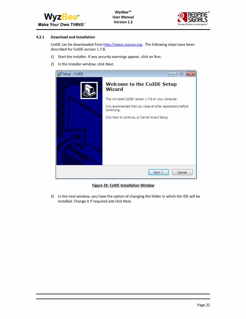
4.2.1 Download and Installation
CoIDE can be downloaded from http://www.coocox.org . The following steps have been described for CoIDE version 1.7.8.
1) Start the installer. If any security warnings appear, click on Run.
2) In the Installer window, click Next.
Figure 24: CoIDE Installation Window
3) In the next window, you have the option of changing the folder in which the IDE will be installed. Change it if required and click Next.

Page 23
WyzBee™ User Manual Version 1.2
WyzBee™ User Manual Version 1.2
Figure 25: CoIDE Installation Folder Selection
4) In the new window, click Install to start the Installation of CoIDE.
Figure 26: CoIDE Installation Start
5) Click Finish after the installation is completed.

Page 24
WyzBee™ User Manual Version 1.2
WyzBee™ User Manual Version 1.2
6) CoIDE doesn't come with an integrated GCC compiler. Download and install the relevant GCC toolchain for Windows from https://launchpad.net/gcc-arm-embedded/
7) Once the installation of the GCC Toolchain is completed, open CoIDE and click on “Select Toolchain Path” under “Project”. In the new dialog box that opens, enter the path where the GCC Toolchain was installed.
Figure 27: GCC Toolchain Path for CoIDE
8) To verify the downloaded version,click Help -> About CoIDE
Figure 28: CoIDE Version
4.2.2 Configuring CoIDE for WyzBee™
Follow the steps below to configure CoIDE for WyzBee™.
1) Open CoIDE and click on the Configuration button.
Figure 29: CoIDE Configuration Button
2) In the new window that opens, ensure that the settings on each tab match the settings in the images below.

Page 25
WyzBee™ User Manual Version 1.2
WyzBee™ User Manual Version 1.2
Figure 30: CoIDE Configuration – Device
Figure 31: CoIDE Configuration – Link

Page 26
WyzBee™ User Manual Version 1.2
WyzBee™ User Manual Version 1.2
Figure 32: CoIDE Configuration – Output
Figure 33: CoIDE Configuration – User
Figure 34: CoIDE Configuration – Debugger

Page 27
WyzBee™ User Manual Version 1.2
WyzBee™ User Manual Version 1.2
Figure 35: CoIDE Configuration – Download
4.3 IAR Embedded Workbench
IAR Embedded Workbench is a development environment that includes a C/C++ compiler and debugger.
4.3.1 Download and Installation
The IAR Embedded Workbench can be downloaded from https://www.iar.com. The following steps have been described for IAR version 7.30.
1) Start the installer. If any security warnings appear, click on Run.
2) In the installation window, selection the “Install IAR Embedded Workbench” option.

Page 28
WyzBee™ User Manual Version 1.2
WyzBee™ User Manual Version 1.2
Figure 36: IAR Embedded Workbench Installation Window
3) In the new window, click Next.
Figure 37: IAR Embedded Workbench Installation Window
4) Check the “I accept the terms of the license agreement” option and click Next.

Page 29
WyzBee™ User Manual Version 1.2
WyzBee™ User Manual Version 1.2
Figure 38: IAR Embedded Workbench License Agreement
5) In the next window, you have the option of changing the folder in which the IDE will be installed. Change it if required and click Next.
Figure 39: IAR Embedded Workbench Installation Folder

Page 30
WyzBee™ User Manual Version 1.2
WyzBee™ User Manual Version 1.2
6) Click Next in the new window and then click Install to start the installation process.
Figure 40: IAR Embedded Workbench Installation Start
7) Wait for the installation to be completed. You will be requested to remove any USB dongles connected to the PC. Remove them and click Yes.
Figure 41: IAR Embedded Workbench – Dongle Drivers Installation
8) This will start the installation of the dongle drivers. Once completed, select the “Launch IAR Embedded Workbench for ARM” option and click Finish to complete the installation of IAR Embedded Workbench.

Page 31
WyzBee™ User Manual Version 1.2
WyzBee™ User Manual Version 1.2
Figure 42: IAR Embedded Workbench Installation Completed
9) Next, you will be prompted for installation of device software. Click Install.
Figure 43: IAR Embedded Workbench – Device Software – 1

Page 32
WyzBee™ User Manual Version 1.2
WyzBee™ User Manual Version 1.2
Figure 44: IAR Embedded Workbench – Device Software – 2
10) Select the Language of your preference and click OK.
Figure 45: IAR Embedded Workbench – Language Selection
11) The IAR Embedded Workbench window opens, followed by the License Wizard. Click Next.
Figure 46: IAR Embedded Workbench – License Wizard
12) Click Next again.

Page 33
WyzBee™ User Manual Version 1.2
WyzBee™ User Manual Version 1.2
Figure 47: IAR Embedded Workbench – License Wizard (Choose a Product)
13) In the new window, click Register.
Figure 48: IAR Embedded Workbench – License Wizard (Register)

Page 34
WyzBee™ User Manual Version 1.2
WyzBee™ User Manual Version 1.2
14) Clicking Register opens a web browser for the Registration process. Select the “Code Size Limited” option and enter the rest of the details.
Figure 49: IAR Embedded Workbench: Registration
15) Once the details are submitted, a confirmation email is sent to the registered email address. Open the confirmation email and click on the confirmation link.
16) Next, a page opens with a License Key.

Page 35
WyzBee™ User Manual Version 1.2
WyzBee™ User Manual Version 1.2
Figure 50: IAR Embedded Workbench: Registration Complete
17) Copy this key and paste it in the License Wizard and click Next to complete the installation and registration process for IAR Embedded Workbench.
4.3.2 Configuration IAR Embedded Workbench for WyzBee™
1) Open the IAR Embedded Workbench and click on Project Options
Figure 51: IAR Embedded Workbench – Project Options

Page 36
WyzBee™ User Manual Version 1.2
WyzBee™ User Manual Version 1.2
2) In the Options window that opens, ensure that all settings are as per the images shown below.
Figure 52: IAR Embedded Workbench – Options – 1
Figure 53: IAR Embedded Workbench – Options – 2
3) Click OK to complete the configuration for WyzBee™.

Page 37
WyzBee™ User Manual Version 1.2
WyzBee™ User Manual Version 1.2
5 Appendix B: WyzBee™ Headers
The WyzBee™ baseboard comes with 2 16-pin THING™ Headers. These headers can be used to add a combination of multiple THING™ boards.
Figure 54: 32-pin WyzBee™ THING Header
5.1 Pin Description
The table below describes the pins of the WyzBee™ baseboard’s Headers.
Pin Name Function Direction Description
THING Headers
S1 P56 Inout General-purpose Input/Output
SOT6_0/SDA6_0 Output/Inout Multi-function Serial Interface
Channel 6 Output/Inout
INT08_2 Input External Interrupt 8
S2 P55 Inout General-purpose Input/Output
SIN6_0 Input Multi-function Serial interface
Channel 6 Input
RTO15_0 Output Waveform generator output of
Multi-function timer 15

Page 38
WyzBee™ User Manual Version 1.2
WyzBee™ User Manual Version 1.2
Pin Name Function Direction Description
INT07_2 Input External Interrupt 7
S3 P31 Inout General-purpose Input/Output
TIOB1_1 Inout Base Timer Channel 1 TIOB pin.
This can be used only if S16 is
not configured as TIOB1_0.
SIN3_1 Input Multi-function Serial interface
Channel 3 Input
INT09_2 Input External Interrupt 9
S4 P33 Inout General-purpose Input/Output
TIOB3_1 Inout Base Timer Channel 3 TIOB pin.
This can be used only if S17 is
not configured as TIOB3_0.
SCK3_1/SCL3_1 Output Multi-function Serial interface
Chanel 3 Clock output
INT04_1 Input External Interrupt 4
S5 P32 Inout General-purpose Input/Output
TIOB2_1 Inout Base Timer Channel 2 TIOB pin.
This can be used only if S14 is
not configured as TIOB2_0.
SOT3_1/SDA3_1 Output/Inout Multi-function Serial Interface
Channel 3 Output/Inout
INT10_1 Input External Interrupt 10
S6 P3B Inout General-purpose Input/Output
TIOA1_1 Inout Base Timer Channel 1 TIOA pin
BIN0_0 Input QPRC Channel 0 BIN Input
RTO01_0 Output Waveform generator output of
Multi-function timer 1
S7 P3C Inout General-purpose Input/Output
TIOA2_1 Inout Base Timer Channel 2 TIOA pin

Page 39
WyzBee™ User Manual Version 1.2
WyzBee™ User Manual Version 1.2
Pin Name Function Direction Description
ZIN0_0 Input QPRC Channel 0 ZIN Input
RTO02_0 Output Waveform generator output of
Multi-function timer 2
S8 MCU_RESET_N Input External reset
S9 P23 Inout General-purpose Input/Output
TIOA7_1 Inout Base Timer Channel 7 TIOA pin
RTO00_1 Output Waveform generator output of
Multi-function timer 0
AN15 Input ADC Input Channel 15
S10 P44 Inout General-purpose Input/Output
TIOA4_0 Inout Base Timer Channel 4 TIOA pin
RTO14_1 Output Waveform generator output of
Multi-function timer 14
DAC0 Output DAC Output Channel 0
S11 P16 Inout General-purpose Input/Output
SIN2_2 Input Multi-function Serial interface
Channel 2 Input
INT14_1 Input External Interrupt 14
AN06 Input ADC Input Channel 6
S12 P17 Inout General-purpose Input/Output
SOT2_2 Output Multi-function Serial Interface
Channel 2 Output
AN07 Input ADC Input Channel 7
WKUP3 Input Deep standby mode return
Channel 3 Input
S13 P18 Inout General-purpose Input/Output
SCK2_2/SCL2_2 Output Multi-function Serial interface

Page 40
WyzBee™ User Manual Version 1.2
WyzBee™ User Manual Version 1.2
Pin Name Function Direction Description
Chanel 2 Clock output
AN08 Input ADC Input Channel 8
S14 VDD_5V Output 5V Output Power Supply for
THING boards.
S15 GND Ground Ground
S16 VIN_EXT Input External Power Supply. This can
be from different sources like
battery THING.
S12 P15 Inout General-purpose Input/Output
SCK0_1/SCL0_1 Output Multi-function Serial interface
Chanel 0 Clock output
AN05 Input ADC Input Channel 5
S17 VDD_3V3 Output 3.3V Output Power supply
S18 P4C Inout General-purpose Input/Output
TIOB2_0 Inout Base Timer Channel 2 TIOB pin
SCK7_1/SCL7_1 Output Multi-function Serial interface
Chanel 7 Clock output
AIN1_2 Input QPRC Channel 1 AIN Input
S19 P4E Inout General-purpose Input/Output
TIOB4_0 Inout Base Timer Channel 4 TIOB pin
SIN7_1 Input Multi-function Serial interface
Channel 7 Input
ZIN1_2 Input QPRC Channel 1 ZIN Input
INT11_1 Input External Interrupt 11
WKUP2 Input Deep standby mode return
Channel 2 Input
S20 P4B Inout General-purpose Input/Output

Page 41
WyzBee™ User Manual Version 1.2
WyzBee™ User Manual Version 1.2
Pin Name Function Direction Description
TIOB1_0 Inout Base Timer Channel 1 TIOB pin.
This can be used only if S12 is
not configured as TIOB1_1.
SCS7_1 Output Multi-function Serial interface
Channel 7 Chip Select
S21 P4D Inout General-purpose Input/Output
TIOB3_0 Inout Base Timer Channel 3 TIOB pin.
This can be used only if S3 is not
configured as TIOB3_0.
SOT7_1/SDA7_1 Output/Inout Multi-function Serial Interface
Channel 2 Output/Inout
BIN1_2 Input QPRC Channel 1 BIN Input
INT13_2 Input External Interrupt 13
S22 Ground Ground Ground
S23 MCU_VCC33 Output 3.3V Power Supply
S24 P3D Inout General-purpose Input/Output
TIOA3_1 Inout Base Timer Channel 3 TIOA pin
RTO03_0 Output Waveform generator output of
Multi-function timer 3
S25 VDD_MOD Output 3.3V Output Power supply
S26 P3A Inout General-purpose Input/Output
TIOA0_1 Inout Base Timer Channel 0 TIOA pin
AIN0_0 Input QPRC Channel 0 AIN Input
RTO00_0 Inout Waveform generator output of
Multi-function timer 0
S27 P14 Inout General-purpose Input/Output
SOT0_1/SDA0_1 Output/Inout Multi-function Serial Interface
Channel 0 Output/Inout

Page 42
WyzBee™ User Manual Version 1.2
WyzBee™ User Manual Version 1.2
Pin Name Function Direction Description
IC03_2 Input 16-bit input capture Channel 3
input pin of Multi-function
timer 0
AN04 Input ADC Input Channel 4
S28 P13 Inout General-purpose Input/Output
SIN0_1 Input Multi-function Serial interface
Channel 0 Input
IC02_2 Input 16-bit input capture Channel 2
input pin of Multi-function
timer 0
INT03_1 External Interrupt 3
AN03 Input ADC Input Channel 3
S29 P12 Inout General-purpose Input/Output
SCK1_1/SCL1_1 Output Multi-function Serial interface
Chanel 1 Clock output
IC01_2 Input 16-bit input capture Channel 1
input pin of Multi-function
timer 0
RTCC0_1 Output Reserved
AN02 Input ADC Input Channel 2
S30 P11 Inout General-purpose Input/Output
TX1_2 Output CAN interface Channel 1 TX
output
SOT1_1/SDA1_1 Output/Inout Multi-function Serial Interface
Channel 1 Output/Inout
IC00_2 Input 16-bit input capture Channel 0
input pin of Multi-function
timer 0
AN01 Input ADC Input Channel 1

Page 43
WyzBee™ User Manual Version 1.2
WyzBee™ User Manual Version 1.2
Pin Name Function Direction Description
S31 P10 Inout General-purpose Input/Output
INT02_1 Input External Interrupt 2
RX1_2 Output CAN interface Channel 1 RX
input
SIN1_1 Input Multi-function Serial interface
Channel 1 Input
AN00 Input ADC Input Channel 0
Table 2: Headers Pins Description
*****

Mouser Electronics
Authorized Distributor
Click to View Pricing, Inventory, Delivery & Lifecycle Information: Redpine Signals:
WyzBee-BASE-001 WyzBee-SENS-101 WyzBee-DISP-108 WyzBee-SADK-901 WyzBee-BATT-107