www . electricalpartmanuals
TRANSCRIPT

.""
W ES T I N G H 0 U S E
TYPE RR-5 REGISTER REGULATOR
INST ALLATIDN., OPEFrATIDN . .AND - MAINTENANCE
INSTR UCTION BOOK 5751-A (12-37)
VffiSTINGHOUSE ELECTRIC AND MANUFACTURING COMPANY
EAST PITTSBlJRGH WORKS EAST PITTSBURGH, PA.
,
www . El
ectric
alPar
tMan
uals
. com

I
II
LB. 5751-A
INDEX
DESeR! PTI ON • • • • • • • • • • • . • . • • • • • • • • • . • • • • • • • • • • • • • • • • •
OPERATION • • • • • • • • . • • • . • • • • • . • • • • • • • . • • • • • • • • • • • • • . • "
III GENERAL APPLICATION • • • • • • • . • • • . • . • . • • • . • . • • • • • • • • • • •
Mounting . . • . . . . . . . . . . {J • • • • • • • • • • • • • • • • • • • • • • • • •
Temperature Limits • • • • • • • • . • • . • • • . • . • • • • • • • • • • •
A-C. Supply Voltage • • • • . • • • • • • . • • • • • • • • • • • • • . • •
A-C. Supply Volt-Amperes • • • • • • • . . . • • . • • • • • . • . • •
Relay Contact Capacity . . • . • . . . . • . . . . • . . . . . . . . . . Operations per Minute of Relay . . . • . . . • . . . . . . . • .
Load Circuit Characteristic • • • • • • • • • • • • • . • • • • • • ( A ) A-C. Operation • • • • • • • • • • • • • • • • . • . • • • • • • • .
(B) D-C. Operation • • • • • • • . • • . • . • • • • • • • • • • • • • •
Grid Glow Tube . . • . . . . . • . . . . . . . . . • . . . . . . . . • • . . . •
Sensitivity ................................... . ( A ) Static Operation • • . • • • . • • . • . • • • • • • • • . • • • . (B) Impulse Operation • • . • • . . • . • . • • • • • • • • . • • • •
Speed of Response . • • . • • • • • • • • • • . . • . • • • • • • • • • • • .
Phototube Housing • • • • • • • • • • • • • . • . . • • • • • • • • . • • • .
Light Sources . . . . . . . . . • . . . . . . . . . • . . . . . . . . . . . . . . Scanners for Reflected Light • • • . • • • • • . • . • • . • . • •
IV REGISTER REGULATOR APPLICATIONS • • • • . • • • • • . • . • . . . • . • • General . . fill . . .. . . . . . . . . . . . . f • • • • • • • • • • • • • • • • • • • • • Color of Printed Spot • • • • • • • . • . • • • . • . • • . . • . . . • •
Size of Printed Spot • . . • • . • • • • • . • . • . . . • • . • . • • • •
I mpulse or Static Control • • • • . • . • • • • • • • . • . • • • • •
Ma.xi:mum Paper S peed ............................ . Selector or Limit Switches • • • • • • • • • • • • • . • • . • • • •
3
3 4 4 4 4 4 5 5 5 5 5 6 6 6 7 7 7 7 8
8 8 8 9 9 9 9
V INSTALLATION . • • • • . . . . . . • • . • . • • • • • . • . • . • . . . • . . . • . • . . . 9
VI ADm ST .r.mNT S . . • • • • • . • . • • • • • • • • • • • • . . • . • . • . . • . . • . . . • . . 10
VII TESTING . . . . . . . . . . . . . . . . . . . . . . . . . . . . . . . . . . . . . . . . . . . . .
VIII RENEWAL PARTS . . . . . . . . . . . . . . . . . . . . . . . . . . . . . . . . . . . . . . .
Fig. 1 Fig. 1 Fig. 2 Fig. 3 Fig. 4 Fig. 5 Fig. 6 Fig. 7
ILLUSTRATIONS P Photograph of type RR-5 Register Regulator External Connections Schematic Diagram of Connections Selector Switch Outline Dimensions of RR-5 Register Regulator Type "E" Reflected Light Scanner Type IIF" Reflected Light Scanner
11
12
www . El
ectric
alPar
tMan
uals
. com

WESTINGHOUSE
TYPE RR-5 REGISTER REGULATOR
,I - DESCRIPTION
(1) The RR-5 Register regulator, Fig. 1, is a photo-electrcc relay, which, as shown in Fig. 2 may be connected to give various operating characteristics as needed by differnnt control applications. The register regulator is equipped with a relay operated from a grid glow tube. As shown in Fig. 2 this relay may be made to operate if the illumination on the phototube is either increased or decreased. By connecting the equipment for either "impulse" or "static" control the register regulator will respond to either a transient change in illumination or to a permanent variation in illumination. The equipment may be connected so that the grid glow tube and relay are energized by a d-c. voltage or an a-c. voltage. When d-c. voltage is used the relay will romain in the operated position regardless of subsequent changes in phototube illumination.
As shown in Fig. 2 an external solenoid may be used instead of the relay.
II - OPERATION
(2 ) In Fig. 3 is shown the schematic diagram of connections. The phototube, shown in dotted lines, is connected so that when the illumination on the phototube is increased the grid - cathode voltage of the RJ-57l amplifier tube becomes more negative and the current through the tube decreases. This causes lead 30 to become more negative relative to lead 37. The voltage between 30 and 37 is applied to the grid circuit of the grid glow tube, provided terminals 5-6 are short-circuited. If switch 1 is in the "dark" position the grid glow tube will break down and carry current if the illumination on the phototube ,is decreased. With switch 1 in the IILight" position the grid glow tube will brenk down if the illumination on the phototube is increased. With terminals 5-6 open-circuited the grid glow tube cannot break down regardless of the amount of illumination on the phototube.
The pOSition of the nlug connected to � determines whether "impulse" or "static t, control is used. When " impulse" control is used the equipment responds only to a sudden transient coange in illumination, and does not respond to a gradual change in light intensity, caused for example by lamp voltage va.riations. When "staticl1control is used the operation is controlled by a definite value of illumination on the phototube.
- 3 -
www . El
ectric
alPar
tMan
uals
. com

.r II - OPERATION - Continued
(4) Depending upon the position of switch 2 either a- c, or d-c. voltage is applied to the grid glow tube. When a- c. is used the tube will carry current only so long as the grid voltage of the grid glow tube is more positive than required for breakdown of the tube. When d- c. is used the grid glow tube will continue to carry current regardless of the grid voltage until the switch between 3 and 4 in the anode circuit is opened, thus de-energizing the tube and relay .
III - GENERAL APPLICATION
(5) Mounting:
(6 )
The RR- 5 register regulator should be mounted in a vertical position, preferably in a location with no excessive mechanical vibrations. The phototube housing, the light source or the scanner may be mounted in any position, although the' lamp base should not be higher than the lamp filament in order to prevent excessive heating of the lamp base.
Temperature Limits:
The RR-5 register regulator will operate satisfactorily with ambient air temperatures between 50 degrees F. and 110 degrees F. when a Ku- 627 grid glow tube is used. When a KU-636 grid glow tube is used the ambient air temperature limits are 0 degrees F. to 150 degrees F. The phototuPe may be operated at ambient in temperatures between 0 degrees F. and 150 degrees F.
A-C. Supply Voltage
The maximum variations in a- c. supply voltage should not exceed + 10 per cent from rated voltage as given on the name plate. To obtain the best operating results the a-c. supply voltage should be kept as close to normal as possible. If the a-c. supply voltage is vary ing due to line drop it is recommended to run a separate line from the supply source to the register regulator in order to improve the voltage regulation.
(8) A- C. Supply Volt- Amperes:
The volt-ampere burden of the RR- 5 register regulator is approximately 7 5 Va. when no solenoid is applied. When a solenoid is used the solenoid load must be added to give the total volt-ampere burden.
- 4 -www . El
ectric
alPar
tMan
uals
. com

III - GENERAL APPLICATION - Continued
..
Relay Contact Capacity:
The current interrupting capacity is as follows:
Contacts
One One Two
" Make" "Bree,k" II Make"
in series
Interru]2tins; �� f ' . " .
110 V: "A-C.
20 10
30
220 V.
A-C.
12 6
20
Ca]2acity in Am]2eres
440 v. 125 V. 250 V.
A-C. D-C. D-C.
7 2 0.7 3.5 1 0.4
10 3 1.0
.. Reverse left hand stationary contact.
The continuous current carrying capacity of the relay contact is:
"Make" contacts : 'fBreak" contacts:
12 amperes 6 amperes
(10) Operations per Minute of Relax:
Maximum 300 Recommended: 150
\., (11) Load Circuit Characteristic:
(A) A-C. Operation:
The voltage across terminals 1-3 with switch 2 connected for a-c. operation is half wave rectifier voltage having a crest value of 330 volts. The solenoid or external load must have sufficient reactance to limit the average current between 3 and 4 of Fig. 3 to 0.4 ampere if a KU-627 tube is used or 0.1 ampere if a KU-636 tube is used. These average currents should be read by a d-c. ampere metor. From Fig. 3 it may be seen that a Rectox rectifier is connected between 1 and 3. This Rectox will tend to smooth out the a-c. ripple caused by the rectified a-c. voltage in the load circuit if the reactance of the load is sufficiently high and the load current is low. As the load current is increased above 0.1 ampere the filtering effoct of Rectox 1-3 rapidly decreases.
(B) D-C. Operation:
The load characteristic for d-c. operation is shown in Fig. I of Fig. 2. From these curves may be seen that the average d-c. voltage decreases with increasing load current. The load current as measured by a d-c. ampere meter must not exceed 0.3 ampere if a KU-627 tube is used or 0.1 ampere if a KU-636 tube is used.
- 5 -www . El
ectric
alPar
tMan
uals
. com

�, I
c III - GENERAL APPLICATION - Continued
(12) Grid Glow Tube:
It is recommended that a KU-627 grid glow tube cept where the ambient air temperature exceeds 50 degrees F. to 110 degrees F. In that case, KU-636 tube.
(13) Sensitivitl:
(A) Static Operation:
be used exthe limits use the
The sensitivity of the type RR-5 register regulator when used with static control is 0.007 Lumen. This means that the equipment will operate satisfactorily if the quantity of light on the phototube is changed between zero and 0.007 Lumen. The definition of Lumen is:
L = FC x A
where FC ... illumination in foot candles A = area in square feet of illuminated surface.
The area of the light sensitive cathode of the phototube is approximately 1 square inch and the amount of foot candles to operate the equipment or the sensitivity expressed in foot candles is therefore
Fe ...
0.00,:( 1
TIm 1 foot candle
If an aperture Al square inches is used in front of the phototube the amount of foot candles will be
1 FCI =
Al
It should be noted tnat Al must be less than the area of the phototube cathode. The sensitivity values as given above are based on the assumption that the ilhunination on the phototube is changed between zero and 1 foot candle. If the illumination is changed from for example 10 to 11 foot candles at normal a-c., supply voltage, the illumination limits will decrease if the a-c. supply voltage is decreased. For this reason it becomes necessary to consider the minimum and maximum illumination at minimum and maximum a-c. supply voltage, and to make sure that the minimum illumination at maximum a-c. supply voltage is at least 1 foot candle lower than the maximum illumination at minimum a-c. supply voltage.
- 6 -www . El
ectric
alPar
tMan
uals
. com

III - GENERAL APPLICATION - Continued
(B) Impulse Operation:
When impulse operation is used the RR-5 register regulator will operate on a variation in light of 0.0 15 Lumen corresponding to 2-foot-candle illumination on the phototube. The time during which this change in illumination occurs must not .exceed 0.1 second.
(14) Speed of Response:
(15)
(16)
'When the grid glow tube is connected for a-c. operation the illumination on the phototube must remain changed during two cycles of a-c. supply voltage in order to operate the relay. When d-c. operation is used the relay or solenoid will operate, if the illumination on the phototube remains changed during a time interval of 0.0002 seconds, provided the length of phototube leads does not exceed 6 feet. If longer leads are used the response will be slower due to the time lag caused by the capacity between the leads.
Phototube Housing:
The SK-60 photo tube should be mounted in a phototube housing, for example as shown in Fig. 1 (Price List 18-315). This phototube housing is of the general purpose tJ�e and does not have any aperture in front of the phototube. The phototube housing shown in Fig. 3 (Price List 18-315) is equipped with a 1/211 x 1/16" aperture and is particularly suited for register control applications as outlined in paragraph 18. The phototube should be cormected to the RR-5 control panel by means of cable PDS-7l29. For high speed response (0.0 1 second or faster) the length of the phototube leads must not exceed 6 feet. For other applic'l,tions the phototube leads should not be longer than 25 feet. The phototube leads should be enclosed in a grounded metallic conduit, and there must be no other leads in this conduit.
Light Sources:
A variety of light sources with different foot-candle characteristics are shown in Price List 18-316. By using the data given in paragraph 13 the maximum operating distances for static control with various light sources are found to be as follows:
MAXIMUM OPERATING DISTANCES Style Style Style Style Style Style 829396 849186 831706 831704 854118 822109 40 60 100
Light 829397 849187 Watt Watt W�tt Source Type D Typo E Type F Type G Type H Type K Lamp Lamp Lamp
Distance from li&�t 25' 80' source to phototube.
25' 25'
- 7 -
40' 25' 6.3' 7.8' 10'
www . El
ectric
alPar
tMan
uals
. com

(16) Light Sources - Continued
.-' The type J light source gives an illumination of approximate-\- ly 15,000 foot candles at a distance 3/8 inch from the low
er end of the snout of the housing. The diameter of the beam of light is approximately 3/8 inch.
(17) Scanners for Reflected Light:
IV
(18)
(19)
Two scanners for reflected light are shown in Fig. 7 and Fig. 8 of Price List 18-315. The scanner in Fig. 8 which should preferably be used has a broad light beam approximately 3/16 in. x 5/16 tn. The scanner in Fig. 7 has a concentrated beam approximately 3/32 in. x 1/4 in.
- REGISTER REGULATOR APPLICATIONS
General:
When the RR-5 register regulator is used to control the register of paper or some other material, a spot should be printed on the material and should be used as the register mark. When the material is transparent, as for example cellophane or glassine paper, a dark spot should be printed on it and the type J light source and type D phototube housing should be arranged on opposite sides of the material so that the spot intercepts the beam of light projected on the phototube. When the material is non-transparent a spot with a color contrasting the color Qf the paper should be printed. on the material and a type E or type F scanner for reflected light should be used.
Color of Printed spot:
The spot should preferably have a color which differs photoelectrically as much as possible from the color of the paper. If the color of the paper is white or light yellow the spot color should be black or dark blue. Red colors or colors with red components give approximately the same phototube response as white, light yellow or light blue. Red color should therefore not be used as a "dark" register mark. If, the color of the paper is black, dark blue or brown, a yellOW, white or red spot may be used. The color combinations which may be used in register control applications depend upon the:maximum speed of the paper, the length of the phototube leads, and maximum variation in line voltage. Even though two colors may look similar to the human eye, they may give different response when viewed with a phototube. For this reason it is not practicable to give definite o?erating limits for various color combinations. It is the:::>efore recommended that, before using color combinations which are not sufficiently contrasting, the color response be measured by scanning the two colors with the phototube and observing
- 8 -www . El
ectric
alPar
tMan
uals
. com

(19) Color of Printed Spot - Continued
the deflection on the milliampere meter of the RR-5 register regulator when the equipment is connected for "static" control. If the difference in milliampere meter deflection for the two colors exceeds 0.3 milliampere, the colors may be used for register control applications.
(20) Size of Printed Spot:
The size 'of the printed spot should be 1/16" wide or more inl the direction of travel of the paper. The length of the spot should be 1/2 in�h plus the maximum sideways movement of the paper during normal operation.
(21) ImpUlse or Static Control:
Either "impulse" or "static" control may be used for register control applications. Because the calibration of the equipment is not affected by a-c. line voltage variations or by variations in paper color if impulse control is used� the "impulse" method of control is recommended.
(22) Maximum Paper Speed:
The mnximum permissable paper speed depends upon (1) the difference between paper color and sRot color, (2) the length of the phototube leads, and, (3) if 'static" control is used the variations in a-c. supply voltage. If a black spot on white paper is used a maximum paper speed of 1500 feet per minute may be used, provided the length of the phototube leads does not exceed 6 feet. If the lead length is increased tho maximum paper speed will decrease. If the "static" indication by the milliampere meter (between paper color and spot color) is 0. 5 milliamperes, and the length of the phototube leads does not exceed 6 feet, a maximum paper speed of 600 feet per minute· ma.y by used.
Selector or Limit Switches:
As shown in Fig. 2, selector or llmit switches are used for the purpose of closing the grid glow tube, grid control circuit 5-6 or to interrupt the anode Circuit 3-4. These switches may be in the form of cam-operated contacts deSigned to suit any particular application or may be ccm1ll1Utator type switchos as indicated in Fig. 2. In either case it is important thct the switch be designed so that the insulating resistance between switch segments, or between segments and ground is at least la-million ohms. A commutator type switch, designed for this application, is shown in Fig. 4
v - INSTALLATION
(24) Before installing the RR-5 register regulator read paragraphs 5 to 23 of this instruction book, then install equipment as shown in Fig. 2.
... 9 -www . El
ectric
alPar
tMan
uals
. com

(� \
VI - ADJUSTMENTS
(25) (a) Insert RJ-57l amplifier tube and grid glow tube in their sockets and connect clips to top of tubes.
(b) Turn on a-c. power and allow unit to warm up for five minutes.
(c) "Static" Control:
..
If upper right hand switch is in "DARK" position, and the illumination on the phototube is maximum, turn potentiometer to zero position. Turn potentiometer slowly clockwise until tube breaks down. Observe reading of milliampere meter at tube breakdown. Turn potentiometer counter-clockwise until milliampere meter reading is decreased 0.2 milliampere.
The grid glow tube should now be de-energized. Decrease the illumination on the phototube. This should energize the grid glow tube.
If upper right hand switch is in "LIGHTIt position and the illumination on the phototube is minimum, turn potentiometer all in clockwise. Turn potentiometer slowly counter-clockwise until tube breaks down. Observe reading of milliampere meter at tube breakdown. Turn potentiometer clockwise until the milliampere meter reading is increased 0.2 milliampere.
The grid glow tube should now be de-energized. Increase the illumination on the phototube. This should energize the grid glow tube .
(d) The potentiometer adjustments outlined in preceding paragra.phs are suitable if maximum sensitivity is needed. If the variation in light intensity is considerable it muy be preferable to adjust the potentiometer as follows:
With minimum illumination on the phototube adjust the potentioneter until the grid glow tube breaks down, and observe the potentiometer position. Repeat the test with maximum illumination on the phototube. Make final potentiometer position adjustment midway between the two observed potentiometer pOSitions.
) , (e) Tf:rmpulsC?Cfontrol:
When "impulse" control is used the adjustment should be made as follows:
- 10 -
www . El
ectric
alPar
tMan
uals
. com

(e) "Impulse" Control - Continued
If upper right hand switch is in "Dark" position turn potentiometer clockwiso from zero until grid glow tube breaks down p�d observe the milliampere meter reading at breakdown. TUrn the potentiometer counter-clockwise while the milliampere meter current is reduced 0 .2 milliampere.
If upper right hand switch is in "LIGHT" position turn potentiometer from 100 until grid glow tube breaks down. Observe reading of milliampere meter at breakdown. Turn potentiometer clockwise until milliampere meter reading is increased 0.2 milliampere.
(f) IMPORTANT
KEEP MILLIAMPERE METER SHUNT SWITCH CLOSED EXCEPT WHEN
TESTING EQUIPMENT.
VII - TESTING
(26) �J-571 Tube:
(a) Observe that the tube filament is glowing when the tube is energized. If the filament is not glowing replace the tube.
(b) With phototube dark, or preferably removed from its socket, adjust the potentiometer to give 0 .4 milliampere RJ-571 current. The potentiometer should now be approximately at the 55 position. By moving the potentiometer 3 divisions, the milliampere motor reading should change from 0 .4 to at least 0.3. If this does not obtain replace the RJ-571 tube.
(27 ) Grid Glow Tube:
The grid glow tube should be replaced with a new tube if with switch 1 in the "DARK" position e..nd terminals 5-6 closed it is necessary to change the RJ-571 current more then 0 . 1 milliampere in order to cause the grid glow tube to break down, and pro vent it from breaking down.
(28) If any faulty or erratic operation is observed, first make sure that terminal 7 is properly grounded. Disconnect external leads to terminals 1 to 6 and a-c. and measure the resistance between each external lead and ground. This resistance must be 5-million ohms or higher.
\...- - 11 -
www . El
ectric
alPar
tMan
uals
. com

VIII- RENEWAL PARTS
Name
RJ-571 Amplifier Tube KU-627 or KU-636 Grid Glow Tube SK-60 Phototube Milliampere Meter Potentiometer 20,000 ohms Toggle Switch 2 P. D.T. Toggle Switch S.P. S.T. Socket 4-prong Socket 5-prong Capacitor Rectox7 small Rectox, large Transformer, 115/230 V., 60 cycle Transformer} 220/440 V., 60 cycle Resistor, 13000 ohms Reactor Resistor, 5 megohms Resistor, 1 megohm Resistor, 0.25 megohm Resistor, 0.1 megohm Resistor, 10,000 ohms Resistor, 500 ohms Capacitor 0.01 MF Grid clip for KU tube Grid clip for RJ-571 tube Relay with coil for 60 cycle
- 12 -
Style
RJ-571 KU-627 or KU-636 SK-60 818504
1038329 966576
1014539 793202 831726 948995 971301 966512 966552 966553 943670 850583 829465 860871 861041 860000 799952 911-3634
1014540 829334 799907
1009784
www . El
ectric
alPar
tMan
uals
. com
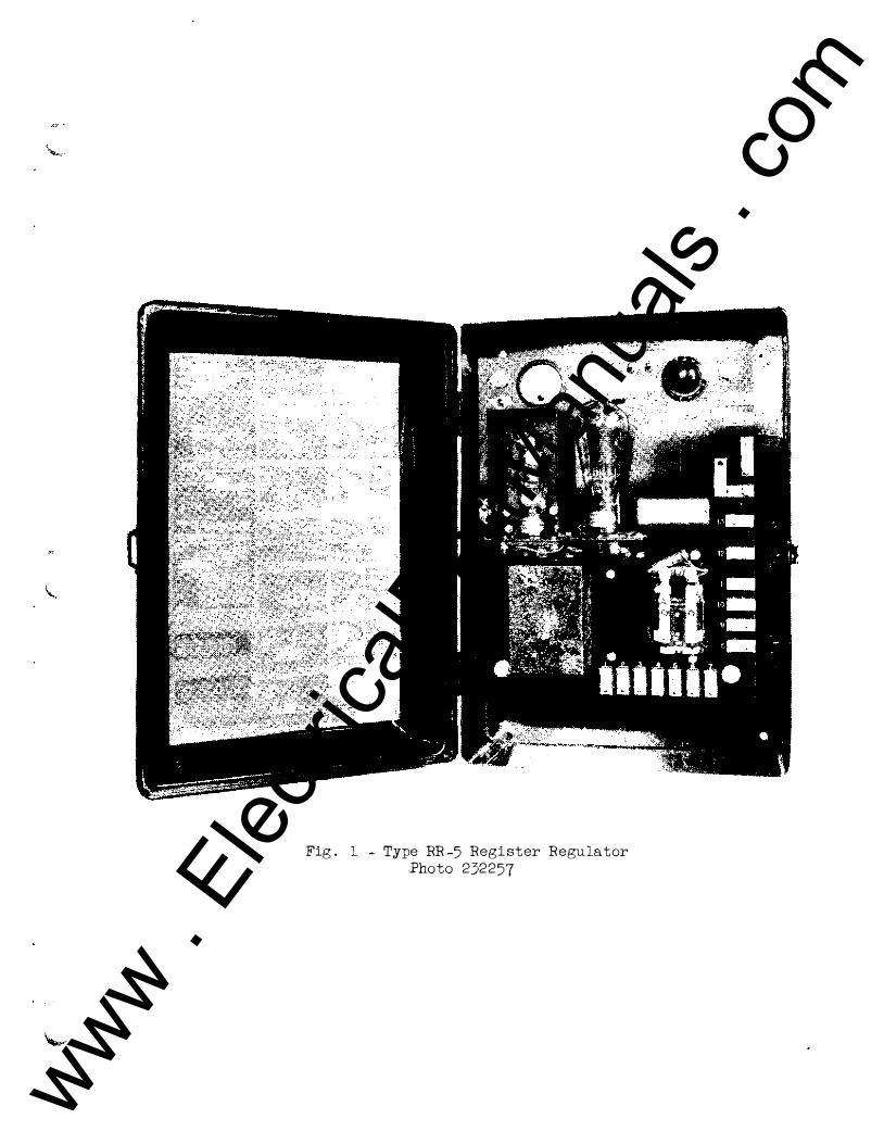
Fig. 1 - Type RR-5 Register Regulator Photo 232257
www . El
ectric
alPar
tMan
uals
. com

Eel�a I!I!!'l'A¥.�rION (pOll lION p� �i ••••• I.B. 5"111)
!9!!!1'IlIliH RII06. RoIgt.to.. _1I"1IIto ... 0 .. Uoal. 1'_"_"" Bo ... l", ... ",. _1111oa. Ligbt a_o, .",. p ... Uloll uoep1l tba1l 111111> 'ba ••• un
lOOt 'be b.!.gl>er tba" 1&IIP 1'11._*,.
WPl!I!ATlI!!I' 1IK06. (Wltb 1.110611'7 tub., .. ,,� Uo"P. 1I1a_ 110'1'. (WUb 1.11�6 tub.,_,,_ l.IlO0p. 111'- 0· ••
I'beutub., __ 160"1'. 111,,_ rf'p. A.p. YOl4'W YAlIHtIOIII! .1lCi111 at ra1l" ,"lllap ... -.
(11M I.B. "Il) C� \III. aitha .. 01' __ 0$1 ... A t. X.
c_eo1l uaU . . . b .... 1" PlS' I. C __ " 1.-.p •• ..b_ i" 1'111. O. ()peN.� "DlRE" _ "LlOIft'" ""Uob po,. 1'111. 1'.
=..�- RoI1II,. Salaaoicl. A.o ])oC IIopul.o 5teUo
" " " " " "
" • • • - - ..
Istyle v��: �: .. T ,ont:l.
O
;:FOB &-8 3.3 '·11
181 11086 1\ 5 r� t�' 10 '7.5
86 .. -10
FlG. P.
;:i:."01
"
,.
'l'bI'0I •• 1toh to "dirk" poalUOD 'OhlD .. 0111,. or 001llnol'" ahould bo .nersl.od 1Ihln tba lU.-iDaUo.. on thl pbatotubo la "'.
ON •• ed..
TbrOi oltoh to "USht" pos1Uon .baD 1'0111,. or oolonold ohou1cl. .be a .. o.,sl.od whln tba lUlIIllnaU ....... tho jIbototubo 10 hor ......
Fig. 2 . External Connections For Type RR-5 Register Regulator
Dwg. 13·J -925
1J.1I!i'!'"J S;��
.
'"
("
1ft �"l.lf.A '51iJ -,.,\1- ,.. .. 1'1 .. I c::s 5r:� •• " .. 1"" JIIIl' PIa. 1'.
-..!,,;...J �OAD (fltWIT
I
A.C. SUppl,.
Lapa_' _ ft,f. O.
i:::�;a{a:;!;.: �":1'1�:�.11::::":�i!;1:i�;::.: �� ph
oto-
"Ught" .... "nao"-OII. '1'bI ",ola,. 11111 •• 1 .. bo "'O .. II ... ,f.tId 1Iho .. tba lU ... l""Uo .. .. oturns to 1Ihe or1g1oal valu ••
Conneet for stati' 3'0 �I 0 onnect per Fig.
A.C. Supply
Lamp connect ,.1' FiS. O.
The solenoid \1111 be &nerr,;lz0d it tbe illul.llnat1on III ve.ried provided the aeleotor awitoh 18 cloaed. The aolenvld 18 d .... enerGized it the 111uminat'1on returns to the o:rlg1nal value Or it the selector 8111toh 1e ope ned.
S.ltoh per Flg. p. II
pel'
... • K\..E.t.lotll.W
'fba .010110101 W1U be o ... rg1ud U" tbe 111umln.t10n on thl photo-
t:b:l�: e:��::r!!I.:��g:t le';:;':�� :�:r:�;::: 0:. ::!:��a: l�;tll t 1l1 .... 1l1Otlon and .oleotor switoh pooltlon untU p ush button PB t. Ol14ned.
'U'W C:l.TJg,I;l tJ ... _ l_ltIOl\ i <oM UlHilOperate Swltoh per F1s. ,.
Conn •• t pe .. Fig. ]I
::1 } �
A.C. SUppl,.
LaIiP oonnea t per Plg. O.
!1M ... 111,. will b • • n.rll.tId 11' tba 1l1 ..... inatiOll Oil tba photo. 'ub. 1. "" .. lt1d. 'l'ha "0111,. will then ramalll .".rs1 •• " ,,"t11 ... .. t b7 PIt.bbu"OIl PB.
AC Connect per F1g. If
A.C. SupplJ
Lamp oonnect pel" P1S. O.
Th. ".,len01d "ill b. enorg1 .ed 11' the illumination on the pb�to_ tUb. 10 lII .... ntarl1,. cbanged p .. ovidod tbe o.lootor owitoh 10 alae.d. The solenoid remaine ettergl •• d until the aelector ..1toh 1e opened" rega.rdlees of further change. ln phototube l11UlOllpa tlon.
p�. II LIlIX CQlmECTIOIIII
O[] J. II lIO'.rE. A-C. PMqueno,. lIUet Be Withln LiaUe •• Speo1t1o'" 011
.... pl.to • liAIinIOil
www . El
ectric
alPar
tMan
uals
. com

PDT. 'TIC ----
j SChemati; Di Dw agram of g. 70-B-724-2
Corme(
www . El
ectric
alPar
tMan
uals
. com

.3
ASSEMBLY
k':J°
I�-'I��ll ' r---Ililtl,,,, I t.nglll� I
3l!DIA ----1 I- -16
I
lass DRILL e..
48-B-503 , I
! __ J I CllHTACT l!',.q FRllI'It"OF 4"lAA�AU.'T � *12 S£!tH£MT. l'IAKI FROM-ITEt'\ , - j ijl!
... 3 5E�"El\r. M�KE FROM -ITEM I ___ a
� "!'.� ... iiii!��'"�'i"'TI<l'l''\.''TA.t''1W- �- - - - . . _ £
tt��ti:i'.'�C:;;:�"",,� r1�-::J� � fl 17!!l!,IE.4-�OtK WASHER __ ._ .?-J
'81"('-64'3�-Ji.!..J\,jul.j.c:,tlIJT __ .. .1 __ 2. '
--·1 1
'I" O�E: oFlri"j;i'i,-WII.L'MAKE OI1E Of ITtM"a All!) Ol'oE Of ITEM' CAI"I4$1lM8LV CGI'IPLlTIt':'-'A6I01" of ITEMS 1708 TW$ 0-,
W'[��V\�K' FROM R!:AR.
(eHOLES)
1 I I �'�DI .. ,-j _jl
- 2*1"A� 3.2'18 I" a.t5o DI .. ,
4
�I
�� VARI .... TIOH� OH F'IHISHEO t)JMEI'ISIONS
UHLE55 OTHE"RWISE MA1'I.K£O t,OIO
Fig. 4 - Selector Switch for Type RR-5 Register Regulator Dwg. 48-B-503
www . El
ectric
alPar
tMan
uals
. com

I
-r �J ����� •
I
E � ...c:=--(, ,
11 - r 1 �
"
.
III - : ,�� . � � • • -+--+----t---tt-- j : � : ; I ir,�
�
I
II
=
Jjl
-t
zJ
; rJi ....., '1/1 '.
� H :)-J-H -$-
Ii
[ ,
-+ n
• 7 ,3 DtA. I<NOC/,t-()VTS
{j :.1"2 (10 KNOCK-OUTS) -'" f.-+A \ -,&
t CD ! ill
t il EIY
li
Fig. 5 - Type RR-5 Register Regulator - Outline Dimensions
Dwg. 39-C-545
�11 4-
BoTTOM WEW
+ i i
12& � ,il-,l /)A. 2 HoLES
www . El
ectric
alPar
tMan
uals
. com

I I I I I >--- - ;::..- -::.l..J,JI.--L..., I I I L......!"'I'T"""""......-' , I
Fig. 6 - Type E Reflected Light Scanner Dwg. T-67239
. .
Fig. 7 - Type F Reflected Light Scanner Dwg. T-67237
www . El
ectric
alPar
tMan
uals
. com

Supersedes
I ... ue Dated June 8, 1934
PRICE LIST 18-315 EHective November 18, 1935
WESTINGHOUSE INDUSTRIAL MOTORS AND CONTROLLERS
PHOTOTUBE HOUSINGS AND SCANNERS
FIG. 4-TYPE H COMPESSATED SCANNER. FOR
REFLECTED LIGHT. FIG. 5-TvpE G COMPENSATED SCANNER FOR TRANSMITTED LIGHT.
FIG. 1-TYPES A AND B GENERAL PURPOSE
PFiOTorUBE HOUSINGS .
FIG.2-TypE C PHOTOTUBE
HOUSING.
FIG.3-TYPE D PHOTOTUBE
HOUSING. CoMPLETE COMPllNSATION FOR VARIATroNS IN BACKGROUND COLOR OR GLOSSINESS AND FOR LISll VOLTAGE IS OBTAINED Bl1 UNIQUE ClI�CUIT.
@ / ...L,==="'======"'===, SLr:ads
IZflLonq
FIG. 6--TYPE H REFLECTED LIGHT SCANNER. FIG. 7-T YPE � REFLECTED
LIGHT ScANNER.
TABLE I-PHOTOTUBE HOUSINGS
Style Price Without Agprox. Incl.
Tubes hip. Tubes Type Description 0 Wt. 0
A(l) General Purpose. with 10 Ft. leads (l)831 710 5 $19.00 B$ Splash-Proof. with 10 Ft. leads (l)831 708 5 21.00 C. Used Where Space is Limited. no leads 854 11 7 4 23 .00 D For Close-Up Work. 10 ft. leads (l)849 083 4 2.Loo
� Phototube 18-030. Type SR-50 or SK-60 Must be Ordered as Separate Items. Omission Price $7.00. • Stocked W-2 J When leads er than 10 ft. are desired and may be used with the Photo-TrOller, add a separ-
ate item spe desired length of leads PDS-5344. This does not apply to Table 2. Cable $0.15 per foot for length over 10 feet.
TABLE 2-SCANNERS
Style Price TUBES REQUIRED
Type Description Witbout !i�;s Ship. Tubes No. Class Type Description Wt.
0 0 I ---
E ! Reflected Light 856471 $40 .00 1 1!Hl30 (l) Phototube }4 I
Narrow Beam 1 18-050 856455 Lamp 12 ft. leads
F Reflected Light 850 679 40.00 1 18-030 (l) Phototube } 4 Broad Beam 1 18-050 856455 Lamp 12 ft. leads
G Transmitted Light 0856424 93 .00 1 18-010 RJ-550 Amplifier ) Compensated 2 18-030 SR-SO Phototube f 7 12 it. leads 2 18-050 856455 Lamp J ,
H Reflected Light @850 640 93.00 1
I 18-010 RJ-550 Amplifier 1
Compensated 2 18-030 SR-SO Phototube J 7 12 ft. leads 2 18-050 856455 Lamp
o When ordering, enter a separate item for tubes as listed. since they are not included in Scanner Style. For omission prices on t ubes see Price List 18-060.
(l) Either SR-50 or SK-6O tubes may be used depending upon application. @ Stocked.
General changes since previous Issue.
rf=31-:i AU -'/6
L
FIG. 8--TYPE F REFLECTED LIGHT SeAmIER •
b 5/� Approx.
I 332 r--II'r---"I I L l!----II
FIG. 9-TYPES A AND B PHOTOTUBE HOUSING.
The Type D Housing is similar except that the light admittance cylinder is replaced by a plate having a plain aperture. The horizontal dimensions are redueed approximately 2 h inches. The general overall dimensions of the type C Housing are: Height O.A. 8)1"; Width O.A. 2"; Depth O.A. 3%;".
ORDERING INSTRUCTIONS
Phototube Housings consist of housing complete with an 18-030 Phototube. Style Numbers do not include Phototube, and a separate item for SR-50 or SK-60 must be entered on order. Prices include Phototube.
Scanners consist of light-source, lens system, photo tube mounting and tubes as listed in Table 2. Tubes and lamps must be entered as separate items according to Table 2, since they are not included in scanner style number.
When Ordering-Specify: (1) Class
18-315, (2) Type, (3) Style. and (4) Application.
Westinghouse Electric & Manufacturing Company W-2
Org. B. Y. Cust. B. S. Y (v) East Pittsburgh, Pa.
EVERY HOUSE NEEDS WESTINGHOUSE www . El
ectric
alPar
tMan
uals
. com

18-315 PRICE LIST
PAGE 2 WESTINGHOUSE !NDUSTlUAL MOTORS AND CONTROLLERS
PHOTOTUBE HOUSINGS AND SCANNERS-Continued
PHOTOTUBE HOUSINGS APPLICATION
18-315 Phototube Housings are general purpose industrial devices for use with 18-316 light sources, and are for the purpose of supplying a socket and housing for phototubes when mounted separately from the photo-electric controller or Photo-Troller, on an extended lead, or on the controller cabinet.
INDIVIDUAL CHARACTERISTICS
Type A-is a cast aluminum housing
for general purpose applications. When
mounted directly on the Photo-Trollers,
it assumes the form of a turret and can
be readily turned on its mounting to
face any direction required, thereby
making it possible to mount the Photo
Troller in any convenient position with
out regard to the direction faced by the
phototube. When the phototube is to
be mounted separately from the Photo
Troller cabinet, and not more than 10
feet away, the housing with the 10-foot
leads should be ordered.
Type B-is identical with the type A
with 10 foot leads except that it is ar
ranged for mounting in applications where it must be splash-proof.
prevents any collection of dust or dirt in the housing and may be used for a surface over which such materials as paper, cellophane or cloth may pass in cutting applications.
INSTALLATION
Phototube Housings may be located in any convenient position and location where mechanical vibration is not so great as to mechanically cause damage and must be rigidly mounted to insure constant alignment with the light beam. While the housings may be mounted up to the maximum distances from the cabinets indicated in the Photo-Troller Price Lists, they should be mounted as near as possible to reduce the length of lead which must be composed of the cable recommended and run without other wires in grounded conduit. It is absolute l y necessary that leads as specified be used with this equipment.
These Phototube Housings must not be operated in an ambient temperature above 160°F. If they are subject to radiant heat as from hot metals, special cooling or heat filters may be requested.
SCANNERS APPLICATION
18-315 Scanners are a combination Type C--consists of a sheet metal
of light source, lens assembly, and housing developed for indoor applica- phototube mounting for applications tions <where space limitations require a housing which is not in excess of two
inches in width.
Type D--comprises a cast aluminum
housing similar to that used with type
A except that the light admittance cyl
inder through which the light enters is replaced simply by a flat plate in
which a window is mounted so that the
phototube may be placed closer to the
material viewed. The glass window
Printed in U. S. A.
requiring scanning or viewing moving material for controlling its motion. These equipments are especially designed for controlling the cutting of paper, cellophane, and similar material in accordance with advertising matter or other printed designs.
INDIVIDUAL CHARACTERISTICS
Type G-is equipped with two phototubes, two lamps, and one amplifier
tube so connected that the difference in
response of the two phototubes feeds
into the single amplifier tube enabling
the equipment to automatically com
pensate for differences in glossiness or
polish of the paper or material being
scanned and at the same time providing
great sensitivity. Furthermore, compensation is provided for changes in tube
characteristics, variations in line voltage,
and other factors which ordinarily
seriously affect the operation of such
equipment unless balanced out. The
practice of mounting the amplifier tube in the scanner also increases the sensitivity and stability of the equipment. The leads to the scanner should be installed in separate grounded conduits. The cable supplied with the scanner must be used in order to reduce the capacity between leads and to make sure that the resistance to ground is high.
Type H-This equipment is identical in operation to Type E, but is to be used when the light is transmitted through the paper rather than reflected from it.
Type E-comprises a single lamp, lens system and phototube mounting and is to be used for reflected light applications where a simpler equipment than the compensated type is required.
Type F-also consists of a single lamp, lens system and phototube and is for reflected light applications where a slightly larger beam or spot of light is required.
INSTALLATION
Scanners should be mounted rigidly in a location as free from vibration as possible and near the Photo· Troller to reduce the length of leads. These scanners must not be used in an ambient temperature above 125°F.
•
www . El
ectric
alPar
tMan
uals
. com

Supersedes I"" ... e Dated June 8, 1934
PRICE LIST 18-316 ERective November 18, 1935
\VESTINGHOUSE I::"IDUSTRIAL MOTORS AND CONTROLLERS ----... --------------------------_._-------
LIGHT SOURCES
FIG. I-TYPE D, LIGHT SoURCE FIG. 2-TYPE E, LONGRANGE LIGHT SOURCE.
FIG. 3-TYPE F, GENERAL PURPOSE LIGHT SoURCE
FIG. 4--TYPE G, SPLASH· PROOF LIGHT SOURCE
ORDERING INSTRUCTIONS
When Ordering
Specify: (1) 18-316, (2) type, (3) des
cription, (4) style number, (5) volts,
(6) cycles, and (7) give application.
light source to phototube, atmospheric ccnditions and application.
Lamps-Types D, F and G light sources are supplied with 6-8 volt, 32 candle-power lamp. Spare lamps should be ordered as 18-050, Style 842108 at $.30 W-31.
FIG. 5-TYPE H. COMPACT LIGHT SOURCE
Note-For special applications where
listed light sources will not fill require·
ments, refer to Works, giving complete
details including illumination require
ments in foot candles, distance from
Types E, H, J and K light sources are supplied with a 6 volt, 5 ampere lamp especially designed for light source service. Spare lamps should be ordered as 18-050, Style 849085 at $1.65 W-31.
'II Style Type Descrlp tion Incl.
Lamp
D General Purpose, with Transfor- $829 396 D mer,. Indoor only. I 829 397
E High Intensity. with Transfor- $849 186 E mer. Indoor and Outdoor. 1849 187
F General Purpose. Indoor only. (j) 831 706
G Splash-Proof. Indoor only. 831 704
H 2"Wide. Indoor only 854 118
J Concentrated Beam. Indoor only. (j)849 084
K General Purpose. Indoor only. 882 109
(j) Stocked,
TABLE 1
II Min. Dist. II ApPRO,.. DIA.
From Lens OF BEAM POWER SUPPLY At Which
II I
I Beam At : ... � __ . : Converiles Converging: To a Pomt Point
At 10
Volts Cycles ' Watts Feet
... �--�--
115/230 25-60 21 3" )4" 10" 220/440 25-60 21 3" )4" tOff
115/230 25-60 35 Infinity .. . 5" 220/440 25-60 35 Infinity ... 5"
(j)5.5 ®a-c. or doc. 18 3" 34" 10"
®5.S ®a-c. or doc. 18 3" 7.(" 10"
@6 0a-c. or doc. 30 Infinity ... 6" @6 @a-c. or doc. 30 I" h" . . . @6 0a-c. or doc. 30 3" !-i" 1011
FIG. 6--TYPE J, Co:.CENTRATED BEAM
LIGHT SoURCE
I I
Shipping ! Price Weight' IncL
Lbs. ' Lamp
11 $24.00 11 24.00
18 27.00 18 27.00
4 15.00
4 16.50
4 19.00
4 19.00
4 lS.00
(j) Connect to allY Class 18-310 Photo-Troller except Types LR & LT. @ Connect to any Class IS-311 Photo-Troller. May also be used with lS-310 RH, RK, and RL Photo-Trollers if ordered similar to Style
except to have 6-S volt, 32 Candlepower lamp, Style S4210S with $0.30 W-31 price omission.
NOTE: AlIl1llht sources except Type] can be supplied with an Infra-red Filter to obtain an almostinvisible light beam. Price addition $1 0,00 W-2 for Type E; $2.00 W-2 for other types.
General changes since previous issue.
Westinghouse Electric & Manufacturing Company Org. B. Y. Cust. B, S. Y (v) East Pittsburgh. Pa.
EVERY HOUSE NEEDS WESTINGHOUSE
W-2
(Ovn) www . El
ectric
alPar
tMan
uals
. com

18-316 PRICE LIST
PAGE 2 WESTINGHOUSE INDUSTRIAL MOTORS AND CONTROLI,ERS
CHARACTERISTICS
Type D-consists of Type FLight Source mounted on cabinet which encloses transformer.
Type E-Extremely powerful beam for long range work.
Type F-Compactness and adaptability. May be mounted on PhotoTroller cabinet or on rigid or flexible conduit.
Type G-Similar to Type F except made splash-proof by use of suitable gaskets and glass window.
Type H-For use where mounting space is at a premium.
Type J-Produces a small, intense and highly concentrated spot of light for accurate close-up work.
DISTINCTIVE FEATURES
Installation costs reduced by eliminating transformer on many types.
High efficiency obtained by convenient and positive focusing adjustments.
Adaptability to application assured by wide selection of types.
Installation simplified by standard conduit fittings or knock outs. Lamps are easily replaced without
disturbing the adjustment of focus.
APPLICATION
18-316 Light sources are for the purpose of supplying a beam 01 light for actuating industrial type photo-electric controllers and light relays. They are especially a d a p t e d for Westinghouse 18-310 and 18-311 Photo-Trollers
The proper light source for operating the photo-electric controller when located at a convenient distance from the phototube should be selected from Fig. 7. It is recommended that as great an excess of illumination as practicable be provided. The minimum illumination required for the operation of Westinghouse Photo-Trollers is listed in Price
Lists 18-310 and 18-311. When the light beam must pass
through a dusty atmosphere or material that is light absorbing, such as water or glass, the illuminating values as shown in Fig. 7 should be decreased by a percentage which is a conservative estimate of the per cent absorption of the atmosphere or material.
When the light beam must be reflected from some surface before it reaches the phototube, the illumina-
LIGHT SOURCES-Continued
JOC
I I I TYPES o,F.G,K TYPE �
1\ 1\
\ \ i \
hpE"'E: \ , !\ \
j i :
1 1\ 1\ 1\ � \ \ \
fl � 1\ � I!: � \ 'I'--.. " "'-
'" " .......... 1"-----f-..- r � '- '-- I (J
o 5 10 " 20 so 85 40
DISTANCE IN FEET FIG. 1-ILLUMIl<ATION INTENSITIES OF VARIOUS TYPES OF LIGHT SoURCES
tion values as shown in Fig. 7 must be multiplied by the reflection coefficient of the surface to obtain an estimate of the illumination that will be available at the phototube.
When an infra-red filter is used for supplying an invisible beam of light, the illumination values shown in Fig. 7 will be reduced to approximately 710 of the values shown.
INDIVIDUAL CHARACTERISTICS
All light sources except the Types D and E are designed to receive power from the Photo-Troller, or a separate transformer. These two types built for supplying their own power, have their own transformer, and may be used for Photo-Troller a p p li c a t i o n s where it would not be practical to run leads from the Photo-Troller to the light source.
Type D-consisting of a cast aluminum lamp housing which may be mounted separately or on the sheet metal transformer box, is a general purpose indoor light source operated directly from an a-c. power stipply rather than from transformer taps of the PhotoTroller. Provision is made for convenient focussing of the light beam.
Type E-is the most powerful light source and is particularly adapted to applications where the operating distance is necessarily large. Like the Type D, it also is operated directly from an a-c. power supply. As it has a Ys inch thick sheet metal cabinet
adequately gasketed, it is suitable for i n d o o r or o u t do o r application. A 3-inch diameter, 4 inch focal length lens is used for concentrating the light from the lamp.
Type F-is very compact consisting simply of a cast aluminum lamp housing. Unusual versatility of application is provided by its design which permits it to be mounted directly on the PhotoTroller cabinet or on % inch flexible or rigid conduit shaped to meet the individual application. A lens slide locked by a thumb screw provides convenient adjustment of the focus of the light beam.
Type G-is similar to Type F, but is splash-proof.
Type H-consists of a sheet metal lamp housing and was developed for indoor applications where space limitations require a light source which is not in excess of 2 inches in width.
Type J-comprises a cast aluminum housing and a special fixed focus lens system which gives a concentrated beam of high intensity for accurate close-up work where the distance between the phototube and light source does not exceed 2 inches.
Type K-is essentially the same in appearance and dimensions as the Type F, but has ventilating holes in the sides like the Type J to provide for the greater heat dissipation necessitated by the more powerful lamp. It is especially suited for general purpose use with the Class 18-311 Photo-Trollers.
Printed in U. S. A.
•
irl n
www . El
ectric
alPar
tMan
uals
. com

•
WESTINGHOUSE ELECTRIC & MANUFACTURING COMPANY
"AKRON. OHIO, 106 South Main St. • ALBANY, N. Y., 456 No. Pearl S •• 'ALEXANDRIA, VA., 1 2 1 Fradet Ave. '"ALLENTOWN, PA., 522 Maple St. • APPLETON. WISC., 1 708 N. Drew St., P.O.
80x 206 tAPPLETON, WISC •• 1029 So. Outagamie St.
• t"ATLANTA, GA., 426 Marietta St., N. W. xATTlCA, N. Y. "BAKERSFIELD, CALIF., 2224 San Emedio St. "BALTIMORE, MD., 1 18 E. Lombard St. tBAL TIMORE, MD., SOl East Preston Road §BALTIMORE, MD., 40 S. Calvert St. "BEAUMONT, TEXAS, 2293 Broadway Ave.,
P. O. 80x 2367 *BINGHAMTON, N. Y., Suite 704, Marine
Midland Bldg., 86 Court St. "BIRMINGHAM, ALA., 2030 Second Ave. "BLUEFIELD, W. VA., 208 Bluefield Avenue fBOISE, IDAHO, P. O. Box 1597 *BOSTON, MASS., 10 High St.
t . BOSTON, MASS., 12 Farnsworth St. "'tBRlOOEPORT, CONN., Bruce Ave. &. Sey·
mour St. @*BUFFALO, N. Y., 814 Ellicott Square Bldg.
t1I' BUFFALO, N. Y., 1 132 Seneca St. "BURLINGTON, IOWA, 1708 River St.
@*BURLINGTON, VER., 207 Park Ave. "BUTTE, MONTANA, 129 West Park St. . BUTTE, MONTANA, 742 Bryant Ave. *CANTON, OHIO, Market &. Tuscarawas Su.
@*CEDAR RAPIDS, IOWA, 813 18.h St., S.E., P. O. 80x 148
*t .CHARLOTTE, N. C., 2 1 0 Eas. Sixth S •• *CHARLESTON, W. V A., 107 Oakmont St.,
P. O. 80x 865 "CHATTANOOGA, TENN., 536 Market St. *CHICAGO, ILL., 20 N. Wacker Drive
t • CHICAGO, ILL., 221 1 W. Pershing Road xCHICOPEE FALLS, MASSACHUSETTS
*t IfICINCINNA TI, OHIO, 207 West Third St. *tx • CLEVELAND, OHIO, 1216 West Fifty·Eighth
St. §COLUMBIA, S. Co, 912 Lady St. *COLUMBUS. OHl<?LPay &. Third St •• *DALLAS, TEXAS. l.IH Browder St. • DALLAS, TEXAS. 1712 Carter St. *DA VENPOR T, IOWA, 206 E. Second St. "DAYTON, OHIO, 30 North Main St. *DENVER, COLORADO, 910 Fifteenth St. • DENVER, COLORADO, 1 700 Sixteenth St. tDENVER, COLORADO, 988 Cherokee St. §DENVER, COLORADO, Gas &. Etec. Bldg. xDERRY, PA. "DES MOINES, IOWA, 523 Sixth Ave.
*t ' DETROIT, MICH., 5757 Trumbull A ve. *DULUTH, MINN., 1 0 East Superior St.
x . EAST PITTSBURGH. PA. (j)*EL PASO, TEXAS, Oregon and Mills Sts.
• EL PASO, TEXAS, 450 Canal St. §EL PASO, TEX., % lork Hdwe. Co., 309 N.
E\ Paso St. (j)* ' tEMERYVILLE, CALIF., 1466 Powell St.
xEMERYVILLE, CALIF., 6161 Green St.
Business Addresses Headquarters, Pittsburgh, Pa.
*ERIE, PA., 1003 St .. e Sr. '"EVANSVILLE, IND., 201 N. W. First St .
*tFAIRMONT, W. VA., 602 Cleveland Ave. SFARGO, N. D., 520-3rd Ave. N. *FORT WAYNE, IND., 1010 Packard Ave • "'FORT WORTH, TEXAS, 501 Jones Se. "FRESNO, CALIF., 872 Peralta Way, P. O. Box
632 *GARY, IND., 701 Washington St. *GRAND RAPIDS, MICH., S07 Monroe Ave.
N. W. "GREENSBORO, N. C., 108 S. Park Drive,
P. O. Box 1828. '"GREENVILLE, S. C., West Earle St. *HAMMOND, IND., 235 167th St.
(j)'HARTFORD, CONN., Main &. Pearl St •. ,
P. O. 80x 745 *HONOLULU. T. Ho, Hawaiian Elee. Co. A�t. • HOUSTON, TEXAS, 1314 Texas Ave.
. HOUSTON, TEXAS, 2313 Commerce Ave. tHOUSTON, TEXAS, 2315 Commerce Ave. §HOUSTON, TEXAS, 611-15 Petroleum Bldg.
(j)* • HUNTINGTON, W. VA., 1029 Seventh Ave. (j)tHUNTINGTON, W. VA., 209 Ninth St.
'"INDIANAPOLIS. 11'10., 137 S. Penna. Ave. tlNDIANAPOLIS, IND., 551 West Merrill St. "ISHPEMING, MICH., 433 High St. *JACKSON, MICH., 212 West Michigan Ave.
.. tJOHNSTOWN, PA., 47 Messenger St. '"JOPLIN, MO .• 420 School Se. *KANSAS CITY, MO., 101 W. Eleventh St.
(j)1fi tKANSAS CITY, MO., 2124 Wyandotte St. *KNOXVILLE, TENN., Gay &. Clinch St. xLIMA, O HIO "LITTLE ROCK, ARK., 1 1 15 West 24th St. §LITTLE ROCK, ARK., % Fone. Bco •. Hdweo,
2nd &. Rock Sr.. *t lfi LOS ANGELES. CALIF., 420 So. San Pedro St.
@*LOUISVILLE, KY., 3;\2 West Broadway "MADISON, WISC., 508 Edgewood Ave. xMANSFIELD, OHIO, 200 East Fifth St. "MARSHALL, TEXAS, 504 Nathan St. "'MEMPHIS, TENN., 130· Madison Ave. "MIAMI, FLA., 1 036 N. Miami Ave. ·MILWAUKEE, WISC., 546 North Broadway tMILWAUKEE, WISC., 1669 N. Water St.
*t lfiMINNEAPOLlS, MINN., 2303 Kennedy St., N. E.
*MONROE, LA., 1301 N. Fourth St. <D*NASHVILLE, TENN., 219 Second Ave" N.
*NEWARK, N. J .• 1 1 80 Raymond Blvd . t • NEWARK, N. J., Haynes Ave. &. Lincoln
Highway xNEWARK, N. J., Plane &. Orange St. *NEW HAVEN, CONN', 42 Church St.
t*NEW ORLEANS, LA., 333 St. Charle. St. • NEW ORLEANS, LA., 527 Poydra. Se. *NEW YORK, N. Y., 150 Broadway tNEW YORK, N. Y., 460 West Thirty·Fourth St. "NIAGARA FALLS, N. Y .• 205 Fall. St, "NORFOLK, VA., 254 Ta,ewell St.
(!)*OKLAHOMA CITY. OKLA., 120 1'1. Robinson Se.
. OKLAHOMA CITY, OKLA.,Third &. Ali. Sts. *OMAHA, NEB .. 409 South Seventeenth Se.
Where addre •• and P. O. bo" are both given, send mail to P. O. box, telegrams to address indicated.
IOMAHA, NEB .. 117 N. 13,h Sr •
*PEORlA, ILL., 104 E. S,ate St. *t lfiPHIL.WELPHIA, PA., 3001 Walnut St.
·PHOENIX, ARIZONA, 1 1 West Jetl"erson S" "PITTSBURGH, PA., Nuttall Work., 200 Mc
Candless Ave. .*PITTSBURGH, PA., 306 4th Ave., 80x 1017
lfi tPITTS8URGH, PA., 543 N. Lang Ave. "PORTLAND, MAINE, 142 High St. *PORTLAND, OREGON, 309 S. W. Six,h Ave tPORTLAND,OREGON, 2138 N.Intemate Ave.
• PORTLAND, OREGON, 720 N. Thompson St.
*tPROVIDENCE, R. I., 16 Elbow St. "RALEIGH, N. C., 803 N"rch Person St. §RALEIGH. N. C., P. O. Box '143. §READING. PA., 619 Spruce St . *RlCHMOND, VA., Fifth &. Byrd
*§ROANOKE, VA., 726 First St., S. E. "tROCHESTER, N. Y., 410 Atlantic Ave.
*ROCKFORD. ILL., 130 South Second St. *SACRAMENTO, CALIF., 1805 20th St. *SALT LAKE CITY. UTAH, 10 We .. Fir.t
South St. t lfi SALT LAKE CITY, UTAH, 346 A Pierpont
Ave . §SALT LAKE CITY, UTAH, McCormick Bldg. *SAN ANTONIO. TEXAS. 1 1 5 W. Travis St.
(j)iSAN FRANCISCO, CALIF., 1355 Matket S •. - SAN FRANCISCO, CAUF., 1 Montgomery
St. ·SEA TTLE, WASH., 603 Stewatt St.
t • SEATTLE, WASH., 3151 East Marginal Way "SHARON, PA., 469 Sharpsville Ave. *SIOUX Y IOWA. 23 1 1 Gwrge St. "SOUTH • IND., 216 East Wayne St. §SOUTH B , IND .• 107 E. Jefferson St. "SOUTH PHILA. WKS., Essington, Pa. "SOUTH PHILA. WKS., P. O. 80x 7348, Phila·
delphia, Pa. *SPOKANE, WASH., So. 158 Monroe St. *SPRlNGFI.ELD, ILL .• 601 E. Adams St., 80" 37
* tSPRINGFIELD, MASS , 395 Ubetty St. xSPRlNGFIELD, MASS., 653 Page 80ulevard *ST. LOUIS, MO., 4I1 North Seventh St.
t ' ST. LOUIS. MO., 717 South Twelfth St. ·SYRACUSE, N. Y., 420 N. Geddes St. *TACOMA, WASH., 1023 "A" St. *TAMPA, FLA .• 417 Ellamae Ave., Box 230 "TOLEDO, OHIO, 245 Summit St. *TULSA, OKLA., 3G3 East Brady St.
• • tUTICA, N. Y . • 113 N. Genesee St. *WASHINGTON , D. C., 1434 New York Ave.,
N. W • *W A TERLOO, IOWA, 328 Jetl"erson St., P. O.
80x 593. . "WICHITA. KAN., 233 So. St. Francis Ave •
*tWILKESoBARRE. PA., 267 N. Pennsylvania Ave.
*tWORCESTER, MASS., 32 SouthbrIdge St. *YORK, PA., 143 So. GeOtRe St. ·YOUNGSTOWN. OHIO, 25 E. 80ardman St,
WESTINGHOUSE ELECTRIC SUPPLY COMPANY Fully equipped sale. offices and warehonses are maintained at all addresses
ALBANY, N. Y., 454 No. Pearl S •• ALLENTOWN, PA., 522 Maple St. ATLANTA, GA., 96 Poplar St., N. W. AUGUSTA, MAINE, 90 Water S •• BALTIMORE, MD., 40 South Calvert St. BANGOR, MAINE, 175 Btoad St. BINGHAMTON, N. Y., 87 Chenango St. BOSTON, MASS .• 76 Pearl St. BURLINGTON, VT., 208 Flynn Ave. BUTTE, MONTANA, 50 East Broadway CHARLOTTE, N. C., 210 East Sixth St. CHICAGO, ILL., 1 1 3 Norrh May St. CLEVELAND, OHIO, 39SO Prospect Ave. COLUMBIA, S. C., 915 Lady St. DALLAS, TEXAS, 409 Browdet St. DES MOINES, IOWA, 218 W. Second St. DETROIT, MICH., 5'*7 Harper Ave. DULUTH, MINN .• 308 W. Michigan St. EVANSVILLE, IND., 201 N. W. First St. FLINT. MICH., 1314 N. Saginaw St. FORT WORTH, TEXAS. 501 Jones St. GRAND RAPIDS, MICH., S07 Monroe Ave.,
N. W. GREENVILLE, S. C., 200 River St. HOUSTON, TEXAS, 1903 Ruh St.
INDIANAPOLIS, IND., 137 S. Pennsylvania St. JACKSONVILLE, FLA., 37 South Hogan St. LOS ANGELES, CALIF., 905 East Second St. MADISON; WISC., 1022 E. Washington Ave. MIAMI, FLA., 1036 North Miami Ave. MEMPHIS, TENN., 366 Madison Ave. MILWAUKEE, WISe, 546 N. Broadway MINNEAPOLIS, MINN., 215 South Fourth St. NEWARK, N. J., 49 Uberty St. NEW HAVEN, CONN., 240 Cedar Se.
.NEW YORK, N. Y., 150 Varick St. NORFOLK, V A., 254 Tazewell St. OAKLAND, CALIF., Tenth &. Alice St •. OKLAHOMA CITY, OKLA., 10 E. California
St. OMAHA, NEB., 1 1 7 North Thirteenth St. PEORIA, ILL., 104 East State Se. PHILADELPHIA, PA., 1 101 Race St. PHOENIX, ARIZONA, 3 1 5 West Jackson St. PORTLAND, OREGON, 134 N.W. Eighth Ave. PROVIDENCE. R. I., 66 Ship St. RALEIGH, N. C., 322 S. Hearrington St. READING, PA., 619 Spruce St. RICHMOND, VA., 301 South Fifth St. ROANOKE. V A., 726 First St .• S. E.
ROCHESTER, N. Y., 240 St. Paul St. ST. LOUIS, MO., 1011 Spruce St. ST. PAUL, MINN., 145 East Fifth Sr. SACRAMENTO, CALIF .. 20th and R Sts. SALT LAKE CITY, UTAH, 235 West South
Temple St. SAN ANTONIO, TEXAS, 1201 E. Houston St. SAN FRANCISCO, CALIF., 260 Fifth St, SEATTLE, WASH., 558 Fi .. t Ave., South SIOUX CITY, lOW A, 1005 Dace St. SPOKANE, WASH .. 152 So. Monroe St. SPRlNGFIELD, MASS., 46 Hampden St. SYRACUSE, N. Y., 961 W. Genesee St. TAMPA, FLA., 417 E!lamae St. TOLEDO, OHIO, 812 Lafavet.e St. TRENTON, N. J., 245 N. Broad St. TULSA, OKLA., 303 East Brady St. UTICA, N. Y., 1 13 N. Genesee St. WASHINGTON, D. C., 1216 UK" St., N. W WATERLOO, IOWA, 328 Jefferson St. WICHITA, KANSAS, 233 So. S •. Ftancls Ave. WILMINGTON, DEL., 216 E. Second St. WORCESTER, MASS., 24 Southbridge St. YORK, PA., 143 S. George St.
* Sales Office t Setvice Shop x Works • Warehouse "First Class Mail Only § Merchan:l.ising Pro:l.ucts Only % HeaJ.quarcers ;Apparatus Produeu Only <!>Changed or added since previous issue. Oetober. 1937
www . El
ectric
alPar
tMan
uals
. com

Business Addresses-Continued
WESTINGHOUSE AGENT JOBBERS ABILENE. KAN •• Union Electric Co. AKRON, OHIO, The Moock Electric Supply
Co. BIRMINGHAM, ALA., Moore-Handley Hdwe.
Co. BLUEFIELD. W. V A., Superior-Sterling Co. B.UFFALO. N. Y .• McCarthy Bro •. & Ford CANTON, OHIO. The Moock Electric Supply
Co. tCHATTANOOGA, TENN., Mills & Lupton
Supply Co. CHICAGO, ILL., Hyland Electrical Supply Co.
CINCINNATI, OHIO, The Johnson Electric· Supply .Co.
§COLUMBUS. OHIO, The Hughes Peters Electric Corporation
COLUMBUS, OHIO. Pixley Electric Supply Co. tDENVER, COL., The.Mine & Smelter Supply
Co. EL PASO, TEX., Zork Hardware Co. ERIE P A.. Star Electrical CO. HUNTINGTON, W. VA .. Banks-Miller Supply
Co. KANSAS OTY, MO., Columbian Elec'l Co.
KANSAS CITY, MO .• Continental Elec. Co. LOUISVILLE. KY., Tafel Electric Co. MONROE. LA., Monro. Hardware Co.
@NASHVILLE. TENN .• r.feI 'Electric Co. NEW ORLEANS. LA., Electrical Supply Co. NEW YORK, N. Y •• Times Appliance Co., Inc. PITTSBURGH, PA., Iron City Electric Co. SAN DIEGO, CAUF., The Electric Supplies
Di stributing Co. SCRANTON, PA., Penn Elect'l Engineering Co. YOUNGSTOWN, OHIO, Moock Electric
Supply Co.
WESTINGHOUSE ELECTRIC & MFG. CO., LAMP DIVISION , *ATLANTA, GA., 426 Marletta St.
*BAL TIMORE, MD .• UB E. Lombard St. xBELLEVILLE. N. J .• 720 Washington Ave.
zxBLOOMFIELD. N". J .• Clearfield Ave. *BOSTON. MASS., 10 High St.
'BOSTON. MASS., 12 Farnsworth St. *BUFFALO N. Y., 295 Main St. *CHICAGO. Ill .• 20 North Wacker Drive 'CHICAGO, ILL.. 22 1 1 W. Pershing Road *CINCINNATI. OHIO, Third & Elm Sts. *CLEVELAND. OHIO, 1216 W. 58th St. *COLUMBUS. OHIO, Gay & Third St. *DAllAS. TEXAS. 209 Browder St. *DA VENPOR T, IOWA. 206 East Second St. *DENVER, COLO., 910 Fifteenrh St. *DES MOINES. IOWA, 218 West Second St.
. *DETROIT. MICH., 5757 Trumbull Ave.
*EMERYVILLE, CALIF .. 1#6 Powell St. *HOUSTON, TEXAS, 1314 Texas Ave. *HUNTINGTON, W. VA., 1029 Seventh Ave. *INDIANAPOLIS. IND .• 137 So. Penna. Ave. '"JACKSON, MICH., Consumers Power Bldg. '"kANSAS OTY, MO., 101 W. Eleventh St.
I(I *LOS ANGELES, CALIF •• 420 S. San Pedro St. OOLOUISVILLE, KY .• 332 We .. Broadway *MEMPHIS. TENN •• 130 Madison St. *MILWAUKEE. WISC •• 546 North Broadway *MINNEAPOLlS, MINN •• 2303 Kennedy St.,
N. E. *NEW ORLEANS, LA., 333 Sr. Charles St. yNEW YORK, N. Y., 150 Broadwal' *OKLAHOMA CITY, OKLA., 10 E. California
St. *OMAHA, NEB •• 409 So. Seventeenth St.
*PHILADELPHIA, PA •• 3001 Walnut St. *PITTSBURGH, PA., 306 4th Ave., Box 1017 1(1 PITTSBURGH, PA., Try St. Terminal Bldg.
@·RICHMOND. VA.. 301 South Fifth St. ·ROCHESTER, N. Y., 240 St. Paul St.
L*SALT LAKE CITY, UTAH. 10 West First r South St. *SAN FRANCISCO, CALIF., 1 Montgomery Sr.
. SAN FRANOSCO. CALIF., 60 Federal St. *SEA TTLE. WASH .• 603 Stewart St.
• SEATTLE, WASH., 3451 East Marginal Way *ST. LOUIS, MO., 'Ill No. Seventh St.
1(1 ST. LOUIS, MO .. 7 1 7 So. 12th Street *SYRACUSE. N. Y., 109 So. Warren Street *TOLEDO, OHIO, 245 SummIt St. xTRENTON, N. I •• 400 Pennington Ave. OOWASHINGTON, D C., 1434N. Y. Ave., N.W
WESTINGHOUSE ELECTRIC ELEVATOR COMPANY @BALTIMORE. MD., 39 Lexington Ave. @BOSTON. MASS., 168 Stuart St. (!)BROOKLYN, N. Y., 528 Bergen St.
BUFFALO. N. Y •• 826 Ellicott Sq. Bldg. C!)xCHICAGO, ILL., 1500 North Branch Sr.
CHICAGO. ILL., 222 No. Bank Drive CINCINNATI. OHIO, Third & Elm Sts. CLEVELAND, OHIO, 842 Rockefeller Bldg. COLUMBld§.d�HIO. Gay & Third Sts. DAllAS, 1 J::.lV\S, 209 Browder St.
@DENVER, COLO., 1052 Gas & Electric Bldg. DES MOINES, IOWA. 523 Sixth Ave. DETROIT. MICH., 5757 Trumbull Ave. DUBUQUE. IOWA. c/o Roshek Store
@HARTFORD, CONN., 410 Asylum St. (!)INDIANAPOLIS, IND., 551 W. Merrill St.
@;:xJERSEY OTY, N. J., 150 Pacinc Ave. KANSAS OTY. MO., 101 W. Eleventh St. LOS ANGELES, CALIF., 420 So. San Pedro St.
@NEWARK, N. J., 14 Bridge St. @NEW YORK, N. Y .. 9 Rockefeller Plaza @NEW YORK, N. Y., 128 E. 149 St.
PHILADELPHIA, PA., 3001 Walnut St. PITTSBURGH, PA., 435 Seventh Ave. ST. LOUIS, MO., 'Ill North Seventh St. SAN FRANCISCO, CALIF., I Montgomery St . STEUBENVIllE, OHIO. 306 Nad. Exch. Bldg.
@WASHINGTON, D. C., 1 1 12 21st St., N. W.
WESTINGHOUSE ELECTRIC INTERNATIONAL COMPANY zNEW YORK OTY. N. Y . • 150 Broadway *LONDON. W. C. 2. ENGLAND. 2 Norfolk
St., Strand *SYDNEY, AUSTRALIA, Box 2634-EE. G.P.O. OORIO DE JANElRO. BRAZIL, Calxa Postal 687 .SANTIAGO, CHILE. Casill. 1897 .SHANGHAI. CHINA, P. O. Box 959 "MILANO, ITALY Piazza Crispi 3 .WELLINGTON, NEW ZEALAND, 2 Taranaki
Sr. • UMA, PERU, Edificio Wiese,
Esquina Nun .. y Filiplnas
*MANILA, P. I., P. O. Box 998 *PANAMA. Republic of Panama, P.O. Box 1 1 2 *SAO PAULO. BRAZIL, Caixa Postal 636 *SAN JUAN, Puerto Rico. P. O. Box 1 539 *CIA. WESTINGHOUSE INTERNACIONAL
S. A., Avenkla de Mayo 1035, Buenos Aires, Argentine
*CIA. WESTINGHOUSE ELEC. DE CUBA, Calle Jose de San Martin No •. 16 y IB, Apar. rado 2289, Havana, Cuba
*WESTINGHOUSE ELEC. CO. OF INDIA LTD. Feltham House, Graham Road, Ballard Estate, Bombay, India
*CIA. WESTINGHOUSE ELEC. INTERNAClONAL Edlficio fa Nacional Apartado 78-BI •• Mexico. D. F. Mexico
*MEXICO. (West Coast) Mr. John H. Knost, 1 248 East Fifth Sr., Tuscon, Arizona
*WESTINGHOUSE ELEC CO. OF SOUTH AFRICA, LTD., P. O. Box 6067, Johanne •• burg, South Africa
WESTINGHOUSE X·RAY COMPANY, INC. *ATLANTA, GA .• 565 W. Peachtree St., N. E. *BAL TIMORE, MD., 1 18 East Lombard St. .BOSTON, MASS .• 270 Commonwealth Ave. *CHICAGO. ILL., 512 S. Peoria St. *CLEVELAND. OHIO. 7016 Euclid Ave. *DALLAS, TEXAS, 207 Browder St.
1(1 *DETROIT. MICH .• 5757 Trumbull Ave. zxLONG ISLAND OTY, N. Y., 21-16 43rd Ave.
*LOS ANGELES, CALIF., 420 S. San Pedro St. OOMIL WAUKEE. WISC, 534 North Broadway *NEW ORLEANS. LA., 608 Commercial Place
*NEW YORK, N. Y., 173 E. Eighry-Seventh St. *OMAHA, NEB., 1 17 N. Thirteenth St. ·PHlLADELPHIA, PA., 3001 Walnut St. *PITTSBURGH, PA.:: 3702 Fifth Ave. *ROCHESTER, N. Y., 41 Chestnut sr. ·SAN FRANOSCO, CAW., 870 Market St.
BRYANT ELECTRIC COMPANY "BOSTON. MASS .• 10 High St.
%xBRIDGEPORT. CONN .. Main Plant, 1421 State St. xBRIDGEPORT, CONN., Plastics Division Plant, nos Railroad Ave.
• • CHICAGO. ILL, 844 West Adams St. *NEW YORK. N. Y., 100 East Forry-Second St.
* " SAN FRANOSCO, CAW., 325 Ninth St.
WESTINGHOUSE RADIO STATIONS STATION KDKA, 310 Grant St., Pittsburgh, Pa. STATION WBZ. 271 Tremont St., Boston, Mas •• STATION KYW, 1622 Chestnut St., Philadelphia, Pa. STATION WBZA, Hotel Kimball, Springfiekl. Mass • STATION WOWO. 925 So. Harrison St., Fort Wayne, Ind. STATION WGL, 925 So. Harrison St., Fort Wayne, Ind.
CANADIAN WESTINGHOUSE COMPANY, LIMITED *t .CALGARY, 320 Eighth Avenue West, Calgary. Alberta, Can.
" "'EDMONTON. 10127, 104th St.. Armstrong Block, Edmonton, Alberta. Can. ,,*FORT WILLIAM, 1 1 2 McVicar St .• Fort William. Ontario, Can. I(I*HALIFAX, 158 Granville St . • Halifax. Nova Seotia, Can.
",,*HAMILTON. Hamilton, Ontario, Can. *LONDON, 504 Huron & Erie Bldg., London, Ontario, Canada *MONTREAL, 1 135 Beaver Hall Hill, Montreal, Quebec. Can. IMONTREAL. 400 McGill St., Montreal, Quebec, Can.
(!)Changed or added since previous issue.
1(1 tMONTREAL, 1844 William St., Montreal, Quebec, Can. 1(1 *OTTAWA. Ahearn & Soper LimIted, P. O. Box 779, Ottawa, Ontario, Can. *t 1(1 REGINA, 2408 Eleventh Ave., Regina. Saskatchewan. Can. (!)*SASKATOON. 304 Avenue Bldg .• Saskatchewan. Canada 1 1(1 *sw ASTIKA, Swastika. Ontario, Canada t 1(1 TORONTO, 355 Klnj! St. West, Toronto, Ontario. Can.
*VANCOUVER, 1418 Marine Bldg., Vancouver, B. C., Can. t _VANCOUVER, 1090 Homer St., Vancouver. B. C., Can.
" *tWINNIPEG, 158 Portage Ave. East, Winnipeg, Maniroba, Can.
'" Sales Office t Service Shop x Works • Warehouse , Headquarters y Executive Olliee § MerchandisIng Products Only :t Apparatua Prodw:tl Only
R-816
1ndu.uia1 Relatlo ... October, 1937
Supersedes Issue dated July, 1937
•
www . El
ectric
alPar
tMan
uals
. com