wt2011
DESCRIPTION
WT2011 NISSAN 2011TRANSCRIPT

SUSPENSION
C
D
SECTION WTA
B
T
WROAD WHEELS & TIRES
F
G
H
I
J
K
L
M
N
O
P
CONTENTS
REGULAR GRADE
PRECAUTION ............................................... 3
PRECAUTIONS ................................................... 3
FOR USA AND CANADA ............................................3FOR USA AND CANADA : Precaution for Supple-mental Restraint System (SRS) "AIR BAG" and "SEAT BELT PRE-TENSIONER" ..............................3FOR USA AND CANADA : Precaution for Battery Service ......................................................................3FOR USA AND CANADA : Service Notice or Pre-cautions .....................................................................3
FOR MEXICO ..............................................................3FOR MEXICO : Precaution for Supplemental Re-straint System (SRS) "AIR BAG" and "SEAT BELT PRE-TENSIONER" ...................................................3FOR MEXICO : Precaution for Battery Service .........4FOR MEXICO : Service Notice or Precautions .........4
PREPARATION ............................................ 5
PREPARATION ................................................... 5Special Service Tool .................................................5Commercial Service Tool ..........................................5
SYSTEM DESCRIPTION .............................. 6
COMPONENT PARTS ........................................ 6Component Parts Location ........................................6Component Description .............................................6BCM ..........................................................................6Transmitter ................................................................7Tire pressure receiver ...............................................7Low tire pressure warning lamp ................................7
TPMS ................................................................... 8System Description ...................................................8
DIAGNOSIS SYSTEM (BCM) ............................. 9
COMMON ITEM .......................................................... 9COMMON ITEM : CONSULT-III Function (BCM - COMMON ITEM) ...................................................... 9
AIR PRESSURE MONITOR .......................................10AIR PRESSURE MONITOR : CONSULT-III Func-tion ...........................................................................10
ECU DIAGNOSIS INFORMATION ..............12
BCM ...................................................................12List of ECU Reference .............................................12
WIRING DIAGRAM ......................................13
TIRE PRESSURE MONITORING SYSTEM ......13Wiring Diagram ........................................................13
BASIC INSPECTION ...................................17
DIAGNOSIS AND REPAIR WORK FLOW .......17Work Flow ................................................................17
ADDITIONAL SERVICE WHEN REPLACING BCM ...................................................................19
Description ...............................................................19Work Procedure .......................................................19
TRANSMITTER WAKE UP OPERATION .........20Description ...............................................................20Work Procedure .......................................................20
ID REGISTRATION PROCEDURE ...................21Description ...............................................................21Work Procedure .......................................................21
DTC/CIRCUIT DIAGNOSIS .........................23
C1704, C1705, C1706, C1707 LOW TIRE PRESSURE .......................................................23
Description ...............................................................23DTC Logic ................................................................23Diagnosis Procedure ...............................................23
WT-1Revision: 2010 October 2011 370Z

Special Repair Requirement ................................... 24
C1708, C1709, C1710, C1711 TRANSMITTER ... 25
DTC Logic ............................................................... 25Diagnosis Procedure .............................................. 25Special Repair Requirement ................................... 27
C1716, C1717, C1718, C1719 TRANSMITTER ... 28
DTC Logic ............................................................... 28Diagnosis Procedure .............................................. 28Special Repair Requirement ................................... 29
C1729 VEHICLE SPEED SIGNAL .................... 30Description .............................................................. 30DTC Logic ............................................................... 30Diagnosis Procedure .............................................. 30Special Repair Requirement ................................... 30
C1734 BCM ........................................................ 32DTC Logic ............................................................... 32Diagnosis Procedure .............................................. 32Special Repair Requirement ................................... 33
TIRE PRESSURE RECEIVER ........................... 34Component Function Check ................................... 34Diagnosis Procedure .............................................. 34
LOW TIRE PRESSURE WARNING LAMP ....... 36Component Function Check ................................... 36Diagnosis Procedure .............................................. 36
POWER SUPPLY AND GROUND CIRCUIT ..... 37Diagnosis Procedure .............................................. 37
SYMPTOM DIAGNOSIS ............................. 38
TPMS ................................................................. 38Symptom Table ...................................................... 38
LOW TIRE PRESSURE WARNING LAMP DOES NOT TURN ON ....................................... 41
Description .............................................................. 41Diagnosis Procedure .............................................. 41
LOW TIRE PRESSURE WARNING LAMP DOES NOT TURN OFF ..................................... 42
Description .............................................................. 42Diagnosis Procedure .............................................. 42
LOW TIRE PRESSURE WARNING LAMP BLINKS .............................................................. 43
Description .............................................................. 43Diagnosis Procedure ............................................... 43
ID REGISTRATION CANNOT BE COMPLET-ED ...................................................................... 44
Description .............................................................. 44Diagnosis Procedure .............................................. 44
NOISE, VIBRATION AND HARSHNESS (NVH) TROUBLESHOOTING ............................ 45
NVH Troubleshooting Chart .................................... 45
PERIODIC MAINTENANCE ....................... 46
ROAD WHEEL TIRE ASSEMBLY .................... 46Adjustment .............................................................. 46
REMOVAL AND INSTALLATION .............. 49
ROAD WHEEL TIRE ASSEMBLY .................... 49Exploded View ........................................................ 49Removal and Installation ......................................... 49Inspection ................................................................ 49How to Handle Puncture Repair Agent (With Puncture Repair Kit) ................................................ 50
TRANSMITTER ................................................. 51Exploded View ........................................................ 51Removal and Installation ......................................... 51
TIRE PRESSURE RECEIVER ........................... 53Removal and Installation ......................................... 53
SERVICE DATA AND SPECIFICATIONS (SDS) .......................................................... 54
SERVICE DATA AND SPECIFICATIONS (SDS) ................................................................. 54
Road Wheel ............................................................ 54Tire Air Pressure ..................................................... 54
Nismo 370Z
SPEC CHANGE INFORMATION ............... 55
ROAD WHEEL TIRE ASSEMBLY .................... 55Road Wheel Tire Assembly .................................... 55
WT-2Revision: 2010 October 2011 370Z

PRECAUTIONS[REGULAR GRADE]
C
D
F
G
H
I
J
K
L
M
A
B
T
N
O
P
< PRECAUTION >
W
PRECAUTIONPRECAUTIONSFOR USA AND CANADA
FOR USA AND CANADA : Precaution for Supplemental Restraint System (SRS) "AIR BAG" and "SEAT BELT PRE-TENSIONER" INFOID:0000000006353385
The Supplemental Restraint System such as “AIR BAG” and “SEAT BELT PRE-TENSIONER”, used alongwith a front seat belt, helps to reduce the risk or severity of injury to the driver and front passenger for certaintypes of collision. This system includes seat belt switch inputs and dual stage front air bag modules. The SRSsystem uses the seat belt switches to determine the front air bag deployment, and may only deploy one frontair bag, depending on the severity of a collision and whether the front occupants are belted or unbelted.Information necessary to service the system safely is included in the “SRS AIR BAG” and “SEAT BELT” of thisService Manual.WARNING:• To avoid rendering the SRS inoperative, which could increase the risk of personal injury or death in
the event of a collision that would result in air bag inflation, all maintenance must be performed byan authorized NISSAN/INFINITI dealer.
• Improper maintenance, including incorrect removal and installation of the SRS, can lead to personalinjury caused by unintentional activation of the system. For removal of Spiral Cable and Air BagModule, see “SRS AIR BAG”.
• Never use electrical test equipment on any circuit related to the SRS unless instructed to in this Ser-vice Manual. SRS wiring harnesses can be identified by yellow and/or orange harnesses or harnessconnectors.
PRECAUTIONS WHEN USING POWER TOOLS (AIR OR ELECTRIC) AND HAMMERSWARNING:• When working near the Air Bag Diagnosis Sensor Unit or other Air Bag System sensors with the
ignition ON or engine running, never use air or electric power tools or strike near the sensor(s) witha hammer. Heavy vibration could activate the sensor(s) and deploy the air bag(s), possibly causingserious injury.
• When using air or electric power tools or hammers, always switch the ignition OFF, disconnect thebattery, and wait at least 3 minutes before performing any service.
FOR USA AND CANADA : Precaution for Battery Service INFOID:0000000006353386
Before disconnecting the battery, lower both the driver and passenger windows. This will prevent any interfer-ence between the window edge and the vehicle when the door is opened/closed. During normal operation, thewindow slightly raises and lowers automatically to prevent any window to vehicle interference. The automaticwindow function will not work with the battery disconnected.
FOR USA AND CANADA : Service Notice or Precautions INFOID:0000000006353387
• Low tire pressure warning lamp blinks for 1min, then turns ON when occurring any malfunction except lowtire pressure. Delete the memory with CONSULT-III, or register the ID to turn low tire pressure warning lampOFF. Refer to WT-21, "Description", WT-21, "Work Procedure".
• ID registration is required when replacing or rotating wheels, replacing transmitter or BCM. Refer to BCS-90,"Exploded View".
• Replace grommet seal, valve core and cap of transmitter in TPMS every tire replacement by reaching wearlimit of tire. Refer to WT-51, "Exploded View".
FOR MEXICO
FOR MEXICO : Precaution for Supplemental Restraint System (SRS) "AIR BAG" and "SEAT BELT PRE-TENSIONER" INFOID:0000000006353388
The Supplemental Restraint System such as “AIR BAG” and “SEAT BELT PRE-TENSIONER”, used alongwith a front seat belt, helps to reduce the risk or severity of injury to the driver and front passenger for certaintypes of collision. Information necessary to service the system safely is included in the “SRS AIR BAG” and“SEAT BELT” of this Service Manual.
WT-3Revision: 2010 October 2011 370Z

[REGULAR GRADE]PRECAUTIONS
< PRECAUTION >WARNING:• To avoid rendering the SRS inoperative, which could increase the risk of personal injury or death in
the event of a collision which would result in air bag inflation, all maintenance must be performed byan authorized NISSAN/INFINITI dealer.
• Improper maintenance, including incorrect removal and installation of the SRS, can lead to personalinjury caused by unintentional activation of the system. For removal of Spiral Cable and Air BagModule, see “SRS AIR BAG”.
• Never use electrical test equipment on any circuit related to the SRS unless instructed to in this Ser-vice Manual. SRS wiring harnesses can be identified by yellow and/or orange harnesses or harnessconnectors.
PRECAUTIONS WHEN USING POWER TOOLS (AIR OR ELECTRIC) AND HAMMERSWARNING:• When working near the Air Bag Diagnosis Sensor Unit or other Air Bag System sensors with the
ignition ON or engine running, never use air or electric power tools or strike near the sensor(s) witha hammer. Heavy vibration could activate the sensor(s) and deploy the air bag(s), possibly causingserious injury.
• When using air or electric power tools or hammers, always switch the ignition OFF, disconnect thebattery, and wait at least 3 minutes before performing any service.
FOR MEXICO : Precaution for Battery Service INFOID:0000000006353389
Before disconnecting the battery, lower both the driver and passenger windows. This will prevent any interfer-ence between the window edge and the vehicle when the door is opened/closed. During normal operation, thewindow slightly raises and lowers automatically to prevent any window to vehicle interference. The automaticwindow function will not work with the battery disconnected.
FOR MEXICO : Service Notice or Precautions INFOID:0000000006353390
• Low tire pressure warning lamp blinks for 1min, then turns ON when occurring any malfunction except lowtire pressure. Delete the memory with CONSULT-III, or register the ID to turn low tire pressure warning lampOFF. Refer to WT-21, "Description", WT-21, "Work Procedure".
• ID registration is required when replacing or rotating wheels, replacing transmitter or BCM. Refer to BCS-90,"Exploded View".
• Replace grommet seal, valve core and cap of transmitter in TPMS every tire replacement by reaching wearlimit of tire. Refer to WT-51, "Exploded View".
WT-4Revision: 2010 October 2011 370Z

PREPARATION[REGULAR GRADE]
C
D
F
G
H
I
J
K
L
M
A
B
T
N
O
P
< PREPARATION >
W
PREPARATIONPREPARATION
Special Service Tool INFOID:0000000006353391
The actual shapes of Kent-Moore tools may differ from those of special service tools illustrated here.
Commercial Service Tool INFOID:0000000006353392
Tool number (Kent-Moore No.)Tool name
Description
–(J-45295)Transmitter activation tool
ID registration
SEIA0462E
Tool name Description
Power tool Loosening wheel nuts
PBIC0190E
WT-5Revision: 2010 October 2011 370Z

[REGULAR GRADE]COMPONENT PARTS
< SYSTEM DESCRIPTION >
SYSTEM DESCRIPTIONCOMPONENT PARTS
Component Parts Location INFOID:0000000006353393
Component Description INFOID:0000000006353394
BCM INFOID:0000000006353395
The BCM reads the tire pressure signal received by the tire pressure receiver, and controls the low tire pres-sure warning lamp and the buzzer operations. It also has a judgment function to detect a system malfunction.
1. Transmitter 2. Tire pressure receiver
A. Wheel B.Low tire pressure warning lamp(On the combination meter)
C. Glove box assembly
D.BCMRefer to BCS-8, "Component Parts Location"
JSEIA0330ZZ
Component parts Function
BCM (Body Control Module) WT-6, "BCM".
Transmitter WT-7, "Transmitter".
Tire pressure receiver WT-7, "Tire pressure receiver".
Turn signal lamp ID registration of each wheel has been completed, turn signal lamp flashes.
Combination meter
Transmits the vehicle speed signal via CAN communication to BCM.
Receives the following signals via CAN communication to BCM.• Low tire pressure warning lamp signal• TPMS warning lamp signal
Low tire pressure warning lamp WT-7, "Low tire pressure warning lamp"
WT-6Revision: 2010 October 2011 370Z

COMPONENT PARTS[REGULAR GRADE]
C
D
F
G
H
I
J
K
L
M
A
B
T
N
O
P
< SYSTEM DESCRIPTION >
W
Transmitter INFOID:0000000006353396
The transmitter integrated with a valve is installed on a wheel, and transmits a detected tire pressure signal byradio wave.
Tire pressure receiver INFOID:0000000006353397
The tire pressure receiver receives the tire pressure signal transmitted by the transmitter in each wheel.
Low tire pressure warning lamp INFOID:0000000006353399
Uses CAN communication from the BCM to illuminate the low tire pressure warning lamp on the combinationmeter.
WT-7Revision: 2010 October 2011 370Z

[REGULAR GRADE]TPMS
< SYSTEM DESCRIPTION >
TPMS
System Description INFOID:0000000006861978
During driving, the TPMS (Tire Pressure Monitoring System) receives the signal transmitted from transmitterinstalled in each wheel. The BCM (Body Control Module) of this system has pressure judgment and troublediagnosis functions. When the tire pressure monitoring system detects low inflation pressure or anotherunusual symptom, the low tire pressure warning lamps in the combination meter comes on.
SYSTEM DIAGRAM
INPUT/OUTPUT SIGNALThe signal transmission/reception between units via a communication line is mainly as listed in the followingtable.
LOW TIRE PRESSURE WARNING LAMP INDICATION CONDITIONUses CAN communication from the BCM to illuminate the low tire pressure warning lamp on the combinationmeter.
JSEIA0157GB
Component parts Signal item
BCMTransmits the following signals via CAN communication to combination meter.• Low tire pressure warning lamp signal
Combination meter Transmits the vehicle speed signal via CAN communication to BCM.
Condition Low tire pressure warning lamp
Ignition switch OFF OFF
Ignition switch ON(system normal)
Warning lamp turns on for 1second, then turns off.
Low tire pressureON
Transmitter ID not registered in BCM
Tire pressure monitoring system malfunction(Other diagnostic item)
Warning lamp blinks 1 min, then turns on.
Tire pressure sensor is in OFF stateBlink
(Blinking pattern depends on the positions of nonoperational tire pressure sensors.)
WT-8Revision: 2010 October 2011 370Z

DIAGNOSIS SYSTEM (BCM)[REGULAR GRADE]
C
D
F
G
H
I
J
K
L
M
A
B
T
N
O
P
< SYSTEM DESCRIPTION >
W
DIAGNOSIS SYSTEM (BCM)COMMON ITEM
COMMON ITEM : CONSULT-III Function (BCM - COMMON ITEM) INFOID:0000000006353403
APPLICATION ITEMCONSULT-III performs the following functions via CAN communication with BCM.
SYSTEM APPLICATIONBCM can perform the following functions for each system.NOTE:It can perform the diagnosis modes except the following for all sub system selection items.
×: Applicable item
NOTE:
*: This item is displayed, but is not used.
FREEZE FRAME DATA (FFD)The BCM records the following vehicle condition at the time a particular DTC is detected, and displays onCONSULT-III.
Diagnosis mode Function Description
Work Support Changes the setting for each system function.
Self Diagnostic Result Displays the diagnosis results judged by BCM.
CAN Diag Support MonitorMonitors the reception status of CAN communication viewed from BCM. Refer to CONSULT-III opera-tion manual.
Data Monitor The BCM input/output signals are displayed.
Active Test The signals used to activate each device are forcibly supplied from BCM.
Ecu Identification The BCM part number is displayed.
Configuration• Read and save the vehicle specification.• Write the vehicle specification when replacing BCM.
System Sub system selection itemDiagnosis mode
Work Support Data Monitor Active Test
Door lock DOOR LOCK × × ×
Rear window defogger REAR DEFOGGER × ×
Warning chime BUZZER × ×
Interior room lamp timer INT LAMP × × ×
Exterior lamp HEAD LAMP × × ×
Wiper and washer WIPER × × ×
Turn signal and hazard warning lamps FLASHER × × ×
— AIR CONDITONER*
• Intelligent Key system• Engine start system
INTELLIGENT KEY × × ×
Combination switch COMB SW ×
Body control system BCM ×
IVIS - NATS IMMU × ×
Interior room lamp battery saver BATTERY SAVER × × ×
Trunk lid open TRUNK × ×
Vehicle security system THEFT ALM × × ×
RAP system RETAINED PWR ×
Signal buffer system SIGNAL BUFFER × ×
TPMS TPMS (AIR PRESSURE MONITOR) × × ×
WT-9Revision: 2010 October 2011 370Z

[REGULAR GRADE]DIAGNOSIS SYSTEM (BCM)
< SYSTEM DESCRIPTION >
AIR PRESSURE MONITOR
AIR PRESSURE MONITOR : CONSULT-III Function INFOID:0000000006353405
FUNCTIONThe diagnosis functions (main functions) include the following: “WORK SUPPORT”, “SELF DIAGNOSTICRESULT”, “DATA MONITOR” and “ACTIVE TEST”.
CONSULT screen item Indication/Unit Description
Vehicle Speed km/h Vehicle speed of the moment a particular DTC is detected
Odo/Trip Meter km Total mileage (Odometer value) of the moment a particular DTC is detected
Vehicle Condition
SLEEP>LOCK
Power position status of the moment a particular DTC is detected
While turning BCM status from low power consumption mode to normal mode (Power supply position is “LOCK”)
SLEEP>OFFWhile turning BCM status from low power consumption mode to normal mode (Power supply position is “OFF”.)
LOCK>ACC While turning power supply position from “LOCK” to “ACC”
ACC>ON While turning power supply position from “ACC” to “IGN”
RUN>ACCWhile turning power supply position from “RUN” to “ACC” (Vehicle is stopping and selector lever is except P position.)
CRANK>RUNWhile turning power supply position from “CRANKING” to “RUN” (From cranking up the engine to run it)
RUN>URGENTWhile turning power supply position from “RUN“ to “ACC” (Emer-gency stop operation)
ACC>OFF While turning power supply position from “ACC” to “OFF”
OFF>LOCK While turning power supply position from “OFF” to “LOCK”
OFF>ACC While turning power supply position from “OFF” to “ACC”
ON>CRANK While turning power supply position from “IGN” to “CRANKING”
OFF>SLEEPWhile turning BCM status from normal mode (Power supply posi-tion is “OFF”.) to low power consumption mode
LOCK>SLEEPWhile turning BCM status from normal mode (Power supply posi-tion is “LOCK”.) to low power consumption mode
LOCKPower supply position is “LOCK” (Ignition switch OFF with steer-ing is locked.)
OFFPower supply position is “OFF” (Ignition switch OFF with steering is unlocked.)
ACC Power supply position is “ACC” (Ignition switch ACC)
ONPower supply position is “IGN” (Ignition switch ON with engine stopped)
ENGINE RUNPower supply position is “RUN” (Ignition switch ON with engine running)
CRANKING Power supply position is “CRANKING” (At engine cranking)
IGN Counter 0 - 39
The number of times that ignition switch is turned ON after DTC is detected• The number is 0 when a malfunction is detected now.• The number increases like 1 → 2 → 3...38 → 39 after returning to the normal condition
whenever ignition switch OFF → ON.• The number is fixed to 39 until the self-diagnosis results are erased if it is over 39.
Diagnostic test mode Function
Work supportIn this mode, it is possible to make quick and accurate adjustments by following the instruc-tions on the CONSULT-III display.
Self diagnostic resultReceives self-diagnosis results from the low tire pressure warning control unit, and indicates DTCs and the number of malfunctions.
WT-10Revision: 2010 October 2011 370Z

DIAGNOSIS SYSTEM (BCM)[REGULAR GRADE]
C
D
F
G
H
I
J
K
L
M
A
B
T
N
O
P
< SYSTEM DESCRIPTION >
W
WORK SUPPORT MODERefer to WT-21, "Work Procedure".
SELF-DIAG RESULTS MODERefer to BCS-84, "DTC Index".
DATA MONITOR MODEScreen of data monitor mode is displayed.NOTE:When malfunction is detected, CONSULT-III perform REAL-TIME DIAGNOSIS.Also, any malfunction detected while in this mode will be displayed at real time.
NOTE:Before performing the self-diagnosis, be sure to register the ID, or erase the actual malfunction location maybe different from that displayed on CONSULT-III.
ACTIVE TEST MODENOTE:Before performing the self-diagnosis, be sure to register the ID, or erase the actual malfunction may be differ-ent from that displayed on CONSULT-III.
TEST ITEM LIST
Data monitorReceives input/output signals from the low tire pressure warning control unit and indicates and stores them to facilitate locating the causes of malfunctions.
Active testTransmits command to the low tire pressure warning control unit to change output signals and check operation of output system.
Diagnostic test mode Function
Monitor item (Unit) Remark
AIR PRESS FL (kPa), (kg/cm2), (Psi)
Air pressure of tiresAIR PRESS FR (kPa), (kg/cm2), (Psi)
AIR PRESS RR (kPa), (kg/cm2), (Psi)
AIR PRESS RL (kPa), (kg/cm2), (Psi)
ID REGST FL1
ID is registered: DoneID is not registered: Yet
ID REGST FR1
ID REGST RR1
ID REGST RL1
WARNING LAMPLow tire pressure warning lamp ON: OnLow tire pressure warning lamp OFF: Off
BUZZERCombination meter buzzer ON: OnCombination meter buzzer OFF: Off
Test item Content
WARNING LAMP This test is able to check to check that the low tire pressure warning lamp turns on.
ID REGIST WARNINGThis test is able to check to check that the buzzer sounds or the low tire pressure warning lamp turns on.
FLASHER This test is able to check to check that each turn signal lamp turns on.
HORN This test is able to check to check that the horn sounds.
WT-11Revision: 2010 October 2011 370Z

[REGULAR GRADE]BCM
< ECU DIAGNOSIS INFORMATION >
ECU DIAGNOSIS INFORMATIONBCM
List of ECU Reference INFOID:0000000006353406
ECU Reference
BCM
BCS-50, "Reference Value"
BCS-81, "Fail-safe"
BCS-83, "DTC Inspection Priority Chart"
BCS-84, "DTC Index"
WT-12Revision: 2010 October 2011 370Z

TIRE PRESSURE MONITORING SYSTEM[REGULAR GRADE]
C
D
F
G
H
I
J
K
L
M
A
B
T
N
O
P
< WIRING DIAGRAM >
W
WIRING DIAGRAMTIRE PRESSURE MONITORING SYSTEM
Wiring Diagram INFOID:0000000006353407
JCEWA0198GB
WT-13Revision: 2010 October 2011 370Z

[REGULAR GRADE]TIRE PRESSURE MONITORING SYSTEM
< WIRING DIAGRAM >
JCEWA0199GB
WT-14Revision: 2010 October 2011 370Z

TIRE PRESSURE MONITORING SYSTEM[REGULAR GRADE]
C
D
F
G
H
I
J
K
L
M
A
B
T
N
O
P
< WIRING DIAGRAM >
W
JCEWA0200GB
WT-15Revision: 2010 October 2011 370Z

[REGULAR GRADE]TIRE PRESSURE MONITORING SYSTEM
< WIRING DIAGRAM >
JCEWA0201GB
WT-16Revision: 2010 October 2011 370Z

DIAGNOSIS AND REPAIR WORK FLOW[REGULAR GRADE]
C
D
F
G
H
I
J
K
L
M
A
B
T
N
O
P
< BASIC INSPECTION >
W
BASIC INSPECTIONDIAGNOSIS AND REPAIR WORK FLOW
Work Flow INFOID:0000000006353408
DETAILED FLOW
1.COLLECT THE INFORMATION FROM THE CUSTOMER
It is also important to clarify customer concerns before starting the inspection. Reproduce the symptom, andunderstand it fully. Interview the customer about the concerns carefully. In some cases, it is necessary tocheck the symptoms by driving the vehicle with the customer.CAUTION:Customers are not professionals. Never assume“maybe the customer means...” or “maybe the cus-tomer mentioned this symptom.
>> GO TO 2.
2.BASIC INSPECTION
1. Turn the ignition switch ON.CAUTION:Never start the engine.
2. Check the tire pressure for all wheels and adjust to the specified value. Refer to WT-54, "Tire Air Pres-sure".
Is the inspection result normal?YES >> GO TO 3.NO >> Inspect or repair the tires or wheels.
3.CHECK LOW TIRE PRESSURE WARNING LAMP
Check low tire pressure warning lamp display.Does not low tire pressure warning lamp turn OFF?YES >> GO TO 4.NO >> INSPECTION END
4.CRUISE TEST
Start the engine and drive the vehicle.
>> GO TO 5.
5.PERFORM SELF-DIAGNOSIS
With CONSULT-IIIPerform “SELF-DIAG RESULTS” in “AIR PRESSURE MONITOR” of “BCM”.Is any DTC detected?YES >> GO TO 7.NO >> GO TO 6.
6.CHECK SYMPTOM
Perform trouble diagnosis for the applicable symptom. Refer to WT-38, "Symptom Table". Is the cause of the malfunction detected?YES >> GO TO 8.NO >> GO TO 10.
7.CIRCUIT DIAGNOSIS
Inspect the malfunctioning system indicated by the DTC code that is detected during self-diagnosis. Refer toBCS-84, "DTC Index".
>> GO TO 8.
WT-17Revision: 2010 October 2011 370Z
[REGULAR GRADE]DIAGNOSIS AND REPAIR WORK FLOW
< BASIC INSPECTION >
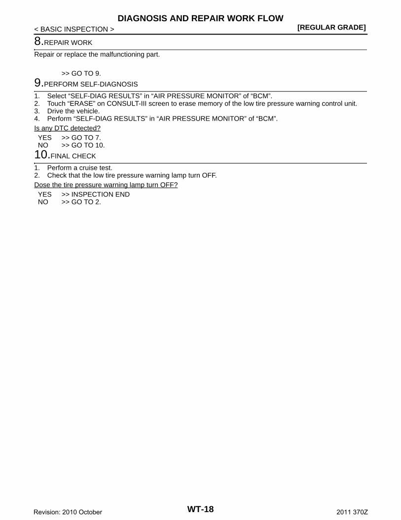
8.REPAIR WORK
Repair or replace the malfunctioning part.
>> GO TO 9.
9.PERFORM SELF-DIAGNOSIS
1. Select “SELF-DIAG RESULTS” in “AIR PRESSURE MONITOR” of “BCM”.2. Touch “ERASE” on CONSULT-III screen to erase memory of the low tire pressure warning control unit.3. Drive the vehicle.4. Perform “SELF-DIAG RESULTS” in “AIR PRESSURE MONITOR” of “BCM”.Is any DTC detected?YES >> GO TO 7.NO >> GO TO 10.
10.FINAL CHECK
1. Perform a cruise test.2. Check that the low tire pressure warning lamp turn OFF.Dose the tire pressure warning lamp turn OFF?YES >> INSPECTION ENDNO >> GO TO 2.
WT-18Revision: 2010 October 2011 370Z

ADDITIONAL SERVICE WHEN REPLACING BCM[REGULAR GRADE]
C
D
F
G
H
I
J
K
L
M
A
B
T
N
O
P
< BASIC INSPECTION >
W
ADDITIONAL SERVICE WHEN REPLACING BCM
Description INFOID:0000000006862344
When replacing BCM, transmitter ID registration is required.
Work Procedure INFOID:0000000006862345
1.PERFORM TRANSMITTER ID REGISTRATION
Perform transmitter ID registration.
>> Refer to WT-21, "Work Procedure".
WT-19Revision: 2010 October 2011 370Z

[REGULAR GRADE]TRANSMITTER WAKE UP OPERATION
< BASIC INSPECTION >
TRANSMITTER WAKE UP OPERATION
Description INFOID:0000000006353409
This procedure must be done after replacement of a transmitter, BCM, or rotation of wheels.
Work Procedure INFOID:0000000006353410
1.TRANSMITTER WAKE-UP PROCEDURE
1. Turn the ignition switch ON.CAUTION:Never start the engine.NOTE:The position of an inactive transmitter can be identified by checking the blinking timing of the low tire pres-sure warning lamp.
2. Contact the transmitter activation tool (J-45295) (1) to the side ofthe tire at the location to the transmitter.
3. Press and hold the activation tool button while pushing the toolto the tire surface. (approximately for 5 seconds)CAUTION:Perform the wake-up procedure starting from the vehiclefront left wheel, then repeat the procedure in the order ofthe front right wheel, rear right wheel, and rear left wheel.
4. Check that the turn signal lamps blink twice when the transmitterwake-up procedure for all wheels is completed.
5. Check that the low tire pressure warning lamp turns OFF, afterthe transmitter wake-up procedure is completed for all wheelsand turns OFF.
Is the transmitter wake-up procedure completed?YES >> Perform the transmitter ID registration procedure. Refer to WT-21, "Work Procedure". NO >> Perform trouble diagnosis for the transmitter. Refer to WT-25, "Diagnosis Procedure".
JPEIC0089GB
NNEIC0020ZZ
WT-20Revision: 2010 October 2011 370Z

ID REGISTRATION PROCEDURE[REGULAR GRADE]
C
D
F
G
H
I
J
K
L
M
A
B
T
N
O
P
< BASIC INSPECTION >
W
ID REGISTRATION PROCEDURE
Description INFOID:0000000006353411
This procedure must be done after replacing or rotating wheels, replacing transmitter or BCM.
Work Procedure INFOID:0000000006353412
1.TRANSMITTER ID REGISTRATION PROCEDURE
With CONSULT-III.1. Display the “WORK SUPPORT” screen and select “ID REGIST”.Is the transmitter activation tool (J-45295) used for the transmitter ID registration procedure?YES >> GO TO 2.NO >> GO TO 3.
2.TRANSMITTER ID REGISTRATION PROCEDURE (WITH TRANSMITTER ACTIVATION TOOL)
1. Turn the ignition switch ON.2. Select the start button on the “ID REGIST” screen.3. Contact the transmitter activation tool (J-45295) (1) to the side of
the tire at the location to the transmitter.4. Press and hold the activation tool button while pushing the tool
to the tire surface. (approximately for 5 seconds)CAUTION:Perform the ID registration procedure starting from thevehicle front left wheel, then repeat the procedure in theorder of the front right wheel, rear right wheel, and rear leftwheel.
5. When ID registration is completed, check the following pattern at each wheel.
6. After the ID registration procedure for all wheels is completed, press “END” to end ID registration, andcheck that ID registration for all wheels is completed.
Is the check result normal?YES >> ID registration END.NO >> Performs trouble-diagnosis of the Tire Pressure Monitoring System (TPMS). Refer to BCS-84,
"DTC Index".
3.TRANSMITTER ID REGISTRATION PROCEDURE (WITHOUT TRANSMITTER ACTIVATION TOOL)
1. Adjust the tire pressure for all wheels to match the list below.
NNEIC0020ZZ
Se-quence
ID registration position Turn signal lamp CONSULT-III
1 Front left wheel
2 blinks“Red”
↓“Green”
2 Front right wheel
3 Rear right wheel
4 Rear left wheel
Tire position Tire pressure kPa (kg/cm2, psi)
Front LH 240 (2.4, 35)
Front RH 220 (2.2, 31)
Rear RH 200 (2.0, 29)
Rear LH 180 (1.8, 26)
WT-21Revision: 2010 October 2011 370Z

[REGULAR GRADE]ID REGISTRATION PROCEDURE
< BASIC INSPECTION >2. Drive the vehicle at a speed at more than 40 km/h (25 MPH) for 3 minutes or more, then perform the
transmitter ID registration procedure.3. After ID registration for all wheels is completed, press “END” to end ID registration.
4. Adjust the tire pressures for all wheels to the specified value. Refer to WT-54, "Tire Air Pressure". Is ID registrations for all wheels completed?YES >> ID registration END.NO >> Performs trouble-diagnosis of the Tire Pressure Monitoring System (TPMS). Refer to BCS-84,
"DTC Index".
ID registration position CONSULT-III
Front LH
“Red”↓
“Green”
Front RH
Rear RH
Rear LH
WT-22Revision: 2010 October 2011 370Z

C1704, C1705, C1706, C1707 LOW TIRE PRESSURE[REGULAR GRADE]
C
D
F
G
H
I
J
K
L
M
A
B
T
N
O
P
< DTC/CIRCUIT DIAGNOSIS >
W
DTC/CIRCUIT DIAGNOSISC1704, C1705, C1706, C1707 LOW TIRE PRESSURE
Description INFOID:0000000006353415
When the tire pressure monitoring system detects low inflation pressure, the low tire pressure warning lampsin the combination meter comes on.
DTC Logic INFOID:0000000006353416
DTC DETECTION LOGIC
NOTE:
• 189.6 kPa (1.9 kg/cm2, 27 psi): Standard air pressure is for 240 kPa (2.4 kg/cm2,35 psi) vehicles.
• 205.1 kPa (2.1 kg/cm2, 30 psi): Standard air pressure is for 260 kPa (2.6 kg/cm2, 38 psi) vehicles.
DTC CONFIRMATION PROCEDURE
1.DTC REPRODUCTION PROCEDURE
With CONSULT-III1. Turn the ignition switch ON.
CAUTION:Never start the engine.
2. Check the tire pressure for all wheels and adjust to the specified value. Refer to WT-54, "Tire Air Pres-sure".
3. Perform “SELF-DIAG RESULTS” in “AIR PRESSURE MONITOR” of “BCM”.Is DTC “C1704”, “C1705”, “C1706”, “C1707” detected?YES >> Perform trouble diagnosis. Refer to WT-23, "Diagnosis Procedure".NO >> INSPECTION END
Diagnosis Procedure INFOID:0000000006353417
1.CHECK TIRE PRESSURE
Check the internal pressure of all wheels. Refer to WT-54, "Tire Air Pressure". Is the inspection result normal?YES >> Replace the DTC-detected malfunctioning transmitter. Refer to WT-51, "Exploded View".NO >> After adjusting the air pressure, GO TO 2.
2.CHECK TIRE PRESSURE SIGNAL
With CONSULT-III1. Drive for 3 minutes at a speed of 40 km/h (25 MPH) or more, then drive normally for 10 minutes.2. Perform “DATA MONITOR” in “AIR PRESSURE MONITOR” of “BCM”.3. Select “BCM” in “DATA MONITOR”, and check that the tire pressures match the standard value.
DTC Display item Malfunction detected condition Possible cause
C1704 LOW PRESSURE FL Front LH tire pressure drops to * kPa (* kg/cm2, * psi) or less. [NOTE]
• Low tire pressure• Transmitter mal-
function
C1705 LOW PRESSURE FR Front RH tire pressure drops to * kPa (* kg/cm2, * psi) or less. [NOTE]
C1706 LOW PRESSURE RR Rear RH tire pressure drops to * kPa (* kg/cm2, * psi) or less. [NOTE]
C1707 LOW PRESSURE RL Rear LH tire pressure drops to * kPa (* kg/cm2, * psi) or less. [NOTE]
WT-23Revision: 2010 October 2011 370Z

[REGULAR GRADE]C1704, C1705, C1706, C1707 LOW TIRE PRESSURE
< DTC/CIRCUIT DIAGNOSIS >
CAUTION:Stop the vehicle and within 5 minutes, use “DATA MONITOR” in “AIR PRESSURE MONITOR” of “BCM”to display the tire pressure for all wheels.Is the inspection result normal?YES >> Inspect or repair the tires or wheels and adjust the tire pressure to the specification.NO >> GO TO 1.
Special Repair Requirement INFOID:0000000006353418
1.CHECK TIRE PRESSURE
Check all tires for tire pressures. Refer to WT-54, "Tire Air Pressure".Does all tire pressure data meet the specification?YES >> GO TO 2.NO >> Inspect or repair the tires or wheels and adjust the tire pressure to the specification.
2.PERFORM ID REGISTRATION
Perform ID registration. Refer to WT-21, "Work Procedure".
>> END
Monitor item Condition Displayed value
AIR PRESS FL
Drive for 3 minutes at a speed of 40 km/h (25 MPH) or more, then drive normally for 10 minutes.
Internal pressure of tiresAIR PRESS FR
AIR PRESS RR
AIR PRESS RL
WT-24Revision: 2010 October 2011 370Z

C1708, C1709, C1710, C1711 TRANSMITTER[REGULAR GRADE]
C
D
F
G
H
I
J
K
L
M
A
B
T
N
O
P
< DTC/CIRCUIT DIAGNOSIS >
W
C1708, C1709, C1710, C1711 TRANSMITTER
DTC Logic INFOID:0000000006353419
DTC DETECTION LOGIC
DTC CONFIRMATION PROCEDURE
1.DTC REPRODUCTION PROCEDURE
With CONSULT-III1. Drive for 3 minutes at a speed of 40 km/h (25 MPH) or more, then drive normally for 10 minutes.2. Perform “SELF-DIAG RESULTS” in “AIR PRESSURE MONITOR” of “BCM”.Is DTC “C1708”, “C1709”, “C1710”, “C1711” detected?YES >> Perform trouble diagnosis. Refer to WT-25, "Diagnosis Procedure".NO >> INSPECTION END
Diagnosis Procedure INFOID:0000000006353420
1.CHECK TIRE PRESSURE SIGNAL
With CONSULT-III1. Drive for 3 minutes at a speed of 40 km/h (25 MPH) or more, then drive normally for 10 minutes.2. Perform “DATA MONITOR” in “AIR PRESSURE MONITOR” of “BCM”.3. Select “BCM” in “DATA MONITOR”, and check that the tire pressures match the standard value.
CAUTION:Stop the vehicle and within 5 minutes, use “DATA MONITOR” in “AIR PRESSURE MONITOR” of “BCM”to display the tire pressure for all wheels.Is a tire pressure of 0 kPa (0 Psi) displayed for all wheels?YES >> GO TO 2.NO >> GO TO 5.
2.CHECK HARNESS BETWEEN BCM AND TIRE PRESSURE RECEIVER
1. Turn the ignition switch OFF.2. Disconnect BCM harness connector and tire pressure receiver harness connector.3. Check the continuity between BCM harness connector and tire pressure receiver harness connector.
DTC Display item Malfunction detected condition Possible cause
C1708 [NO DATA] FLTire pressure data signal from the front left wheel transmitter cannot be detected.
• Harness or connector(Tire pressure receiver, BCM)
• ID registration is not finished• Transmitter malfunction• BCM malfunction
C1709 [NO DATA] FRTire pressure data signal from the front right wheel transmitter cannot be detected.
C1710 [NO DATA] RRTire pressure data signal from the rear right wheel transmitter cannot be detected.
C1711 [NO DATA] RLTire pressure data signal from the rear left wheel transmitter cannot be detected.
Monitor item Condition Displayed value
AIR PRESS FL
Drive for 3 minutes at a speed of 40 km/h (25 MPH) or more, then drive normally for 10 minutes.
Internal pressure of tiresAIR PRESS FR
AIR PRESS RR
AIR PRESS RL
WT-25Revision: 2010 October 2011 370Z

[REGULAR GRADE]C1708, C1709, C1710, C1711 TRANSMITTER
< DTC/CIRCUIT DIAGNOSIS >
4. Check the continuity between BCM harness connector and ground.
Is the inspection result normal?YES >> GO TO 3.NO >> Repair or replace damaged parts.
3.CHECK TIRE PRESSURE RECEIVER POWER SUPPLY CIRCUIT
1. Connect the BCM harness connector.2. Turn the ignition switch ON.
CAUTION:Never start the engine.
3. Check the voltage between the BCM harness connector and ground.
Is the inspection result normal?YES >> GO TO 4.NO >> Repair or replace damaged parts.
4.CHECK TIRE PRESSURE RECEIVER
Check tire pressure receiver. Refer to WT-34, "Diagnosis Procedure".Is the inspection result normal?YES >> GO TO 5.NO >> Replace tire pressure receiver. Refer to WT-53, "Removal and Installation".
5.CHECK ID REGISTRATION
Perform ID registration of all transmitters. Refer to WT-21, "Work Procedure".Can ID registration of all transmitters be completed?YES >> GO TO 6.NO >> Replace transmitter. Refer to WT-51, "Exploded View".
6.CHECK TIRE PRESSURE MONITORING SYSTEM
With CONSULT-III1. Drive at a speed of 40 km/h (25 MPH) or more for several minutes without stopping.2. Perform “DATA MONITOR” in “AIR PRESSURE MONITOR” of “BCM”.3. Select “BCM” in “DATA MONITOR”, and check that the tire pressures match the standard value.
BCM Tire pressure receiverContinuity
Connector Terminal Connector Terminal
M123
137
M101
1
Existed138 4
139 2
BCM— Continuity
Connector Terminal
M123
137
Ground Not existed138
139
BCM— Voltage
Connector Terminal
M123 138 Ground 5 V
WT-26Revision: 2010 October 2011 370Z

C1708, C1709, C1710, C1711 TRANSMITTER[REGULAR GRADE]
C
D
F
G
H
I
J
K
L
M
A
B
T
N
O
P
< DTC/CIRCUIT DIAGNOSIS >
W
CAUTION:Stop the vehicle and within 15 minutes, use “DATA MONITOR” in “AIR PRESSURE MONITOR” of“BCM” to read the tire pressure for all wheels.Is the inspection result normal?YES >> Replace the DTC-detected malfunctioning transmitter. Refer to WT-51, "Exploded View".NO >> Replace BCM. Refer to BCS-90, "Exploded View".
Special Repair Requirement INFOID:0000000006353421
1.CHECK TIRE PRESSURE
Check all tires for tire pressures. Refer to WT-54, "Tire Air Pressure".Does all tire pressure data meet the specification?YES >> GO TO 2.NO >> Inspect or repair the tires or wheels and adjust the tire pressure to the specification.
2.PERFORM ID REGISTRATION
Perform ID registration. Refer to WT-21, "Work Procedure".
>> END
Monitor item Condition Displayed value
AIR PRESS FL
Drive at a speed of 40 km/h (25 MPH) or more, for several minutes without stopping.
Internal pressure of tiresAIR PRESS FR
AIR PRESS RR
AIR PRESS RL
WT-27Revision: 2010 October 2011 370Z

[REGULAR GRADE]C1716, C1717, C1718, C1719 TRANSMITTER
< DTC/CIRCUIT DIAGNOSIS >
C1716, C1717, C1718, C1719 TRANSMITTER
DTC Logic INFOID:0000000006353422
DTC DETECTION LOGIC
DTC CONFIRMATION PROCEDURE
1.DTC REPRODUCTION PROCEDURE
With CONSULT-III1. Turn the ignition switch ON.
CAUTION:Never start the engine.
2. Check the tire pressure for all wheels and adjust to the specified value. Refer to WT-54, "Tire Air Pres-sure".
3. Perform “SELF-DIAG RESULTS” in “AIR PRESSURE MONITOR” of “BCM”.Is DTC “C1716”, “C1717”, “C1718”, “C1719” detected?YES >> Perform trouble diagnosis. Refer to WT-28, "Diagnosis Procedure".NO >> INSPECTION END
Diagnosis Procedure INFOID:0000000006353423
1.CHECK TIRE PRESSURE
Check the internal pressure of all wheels. Refer to WT-54, "Tire Air Pressure". Is the inspection result normal?YES >> Replace the DTC-detected malfunctioning transmitter. Refer to WT-51, "Exploded View".NO >> After adjusting the tire pressure, GO TO 2.
2.CHECK TIRE PRESSURE SIGNAL
With CONSULT-III1. Check and adjust the tire pressure for all wheels. Refer to WT-54, "Tire Air Pressure". 2. Perform transmitter ID registration for all wheels. Refer to WT-21, "Work Procedure". 3. Drive for 3 minutes at a speed of 40 km/h (25 MPH) or more, then drive normally for 10 minutes.4. Perform “DATA MONITOR” in “AIR PRESSURE MONITOR” of “BCM”.5. Select “BCM” in “DATA MONITOR”, and check that the tire pressures match the standard value.
CAUTION:Stop the vehicle and within 15 minutes, use CONSULT-III “DATA MONITOR” to display the tirepressure for all wheels.
6. Check that “DATA MONITOR” displays tire pressure of 438.60 kPa (4.47 kg/cm2, 63.60 Psi).
Is the inspection 438.60 kPa (4.47 kg/cm2, 63.60 Psi)?YES >> Replace transmitter the tire pressure 438.60 kPa (4.386 bar, 4.47 kg/cm2, 63.60 Psi) displayed.
Refer to WT-51, "Exploded View".NO >> GO TO 1.
DTC Display item Malfunction detected condition Possible case
C1716 [PRESSDATA ERR] FLMalfunction in the tire pressure data from the front left wheel transmitter.
• ID registration is not fin-ished
• Transmitter malfunction
C1717 [PRESSDATA ERR] FRMalfunction in the tire pressure data from the front right wheel transmitter.
C1718 [PRESSDATA ERR] RRMalfunction in the tire pressure data from the rear right wheel transmitter.
C1719 [PRESSDATA ERR] RLMalfunction in the tire pressure data from the rear left wheel transmitter.
WT-28Revision: 2010 October 2011 370Z

C1716, C1717, C1718, C1719 TRANSMITTER[REGULAR GRADE]
C
D
F
G
H
I
J
K
L
M
A
B
T
N
O
P
< DTC/CIRCUIT DIAGNOSIS >
W
Special Repair Requirement INFOID:0000000006353424
1.CHECK TIRE PRESSURE
Check all tires for tire pressures. Refer to WT-54, "Tire Air Pressure".Does all tire pressure data meet the specification?YES >> GO TO 2.NO >> Inspect or repair the tires or wheels and adjust the tire pressure to the specification.
2.PERFORM ID REGISTRATION
Perform ID registration. Refer to WT-21, "Work Procedure".
>> END
WT-29Revision: 2010 October 2011 370Z

[REGULAR GRADE]C1729 VEHICLE SPEED SIGNAL
< DTC/CIRCUIT DIAGNOSIS >
C1729 VEHICLE SPEED SIGNAL
Description INFOID:0000000006353425
BCM detects no vehicle speed signal.
DTC Logic INFOID:0000000006353426
DTC DETECTION LOGIC
DTC CONFIRMATION PROCEDURE
1.DTC REPRODUCTION PROCEDURE
With CONSULT-III1. Drive for several minutes at a speed of 40 km/h (25 MPH) or more, then stop the vehicle.2. Perform “SELF-DIAG RESULTS” in “AIR PRESSURE MONITOR” of “BCM”.Is DTC “C1729” detected?YES >> Perform trouble diagnosis. Refer to WT-30, "Diagnosis Procedure".NO >> INSPECTION END
Diagnosis Procedure INFOID:0000000006353427
1.PERFORM COMBINATION METER SELF-DIAGNOSIS
With CONSULT-IIIPerform “SELF-DIAG RESULTS” of “METER/M&A”.Is any DTC detected?YES >> Check the DTC. Refer to BCS-84, "DTC Index".NO >> GO TO 2.
2.PERFORM SELF-DIAGNOSIS
With CONSULT-IIIPerform “SELF-DIAG RESULTS” in “AIR PRESSURE MONITOR” of “BCM”.Is DTC “C1729” detected?YES >> Replace BCM. Refer to WT-9, "COMMON ITEM : CONSULT-III Function (BCM - COMMON
ITEM)".NO >> GO TO 3.
3.CHECK INFORMATION
With CONSULT-III1. Perform “DATA MONITOR” in “AIR PRESSURE MONITOR” of “BCM”.2. Select “BCM” in “DATA MONITOR”, and check the input/output values. Refer to BCS-50, "Reference
Value". Is the inspection result normal?YES >> Check pin terminal and connection of each harness connector for malfunctioning conditions. NO >> Replace BCM. Refer to BCS-90, "Exploded View".
Special Repair Requirement INFOID:0000000006353428
1.CHECK TIRE PRESSURE
Check all tires for tire pressures. Refer to WT-54, "Tire Air Pressure".Does all tire pressure data meet the specification?YES >> GO TO 2.
DTC number
Trouble diagnosis name DTC detecting condition Possible case
C1729 VHCL SPEED SIG ERR Vehicle speed signal not detected.• CAN communication error• Combination meter malfunction
WT-30Revision: 2010 October 2011 370Z

C1729 VEHICLE SPEED SIGNAL[REGULAR GRADE]
C
D
F
G
H
I
J
K
L
M
A
B
T
N
O
P
< DTC/CIRCUIT DIAGNOSIS >
W
NO >> Inspect or repair the tires or wheels and adjust the tire pressure to the specification.
2.PERFORM ID REGISTRATION
Perform ID registration. Refer to WT-21, "Work Procedure".
>> END
WT-31Revision: 2010 October 2011 370Z

[REGULAR GRADE]C1734 BCM
< DTC/CIRCUIT DIAGNOSIS >
C1734 BCM
DTC Logic INFOID:0000000006353429
DTC DETECTION LOGIC
DTC CONFIRMATION PROCEDURE
1.DTC REPRODUCTION PROCEDURE
With CONSULT-III1. Drive at a speed of 40 km/h (25 MPH) or more for several minutes without stopping.2. Perform “SELF-DIAG RESULTS” in “AIR PRESSURE MONITOR” of “BCM”.
CAUTION:Perform within 15 minutes after stop the vehicle.
Is DTC “C1734” detected?YES >> Perform trouble diagnosis. Refer to WT-32, "Diagnosis Procedure".NO >> INSPECTION END
Diagnosis Procedure INFOID:0000000006353430
1.CHECK BCM POWER SUPPLY
1. Turn the ignition switch OFF.2. Disconnect BCM harness connector.3. Check voltage between BCM harness connector terminals and ground.
Is the power supply normal?YES >> GO TO 2.NO >> Check the following. If any items are damaged, repair or replace damage parts.
• 40A fusible link [No. K located in the fuse block]. Refer to PG-113, "Fuse and Fusible LinkArrangement".
• 10A fuse [No. 10 located in the fuse block (J/B)]. Refer to PG-114, "Fuse, Connector and Termi-nal Arrangement".
• Harness for short or open between battery and BCM harness connector M118 terminal 1.• Harness for short or open between battery and BCM harness connector M119 terminal 11.• Check the Battery voltage.
2.CHECK BCM GROUND
Check the continuity between BCM harness connector and ground.
Is the inspection result normal?YES >> GO TO 3.NO >> Repair or replace damaged parts.
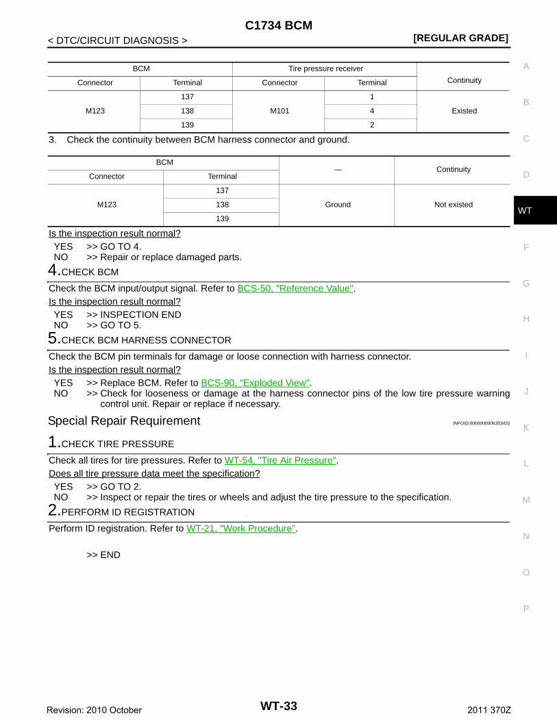
3.CHECK HARNESS BETWEEN BCM AND TIRE PRESSURE RECEIVER
1. Disconnect tire pressure receiver harness connector.2. Check the continuity between BCM harness connector and tire pressure receiver harness connector.
DTC Display item Malfunction detected condition Possible case
C1734 CONTROL UNIT Tire pressure monitoring system malfunction in BCM BCM malfunction
BCM— Voltage
Connector Terminal
M118 1Ground Battery voltage
M119 11
BCM— Continuity
Connector Terminal
M119 13 Ground Existed
WT-32Revision: 2010 October 2011 370Z
C1734 BCM[REGULAR GRADE]
C
D
F
G
H
I
J
K
L
M
A
B
T
N
O
P
< DTC/CIRCUIT DIAGNOSIS >
W
3. Check the continuity between BCM harness connector and ground.
Is the inspection result normal?YES >> GO TO 4.NO >> Repair or replace damaged parts.
4.CHECK BCM
Check the BCM input/output signal. Refer to BCS-50, "Reference Value".Is the inspection result normal?YES >> INSPECTION ENDNO >> GO TO 5.
5.CHECK BCM HARNESS CONNECTOR
Check the BCM pin terminals for damage or loose connection with harness connector.Is the inspection result normal?YES >> Replace BCM. Refer to BCS-90, "Exploded View".NO >> Check for looseness or damage at the harness connector pins of the low tire pressure warning
control unit. Repair or replace if necessary.
Special Repair Requirement INFOID:0000000006353431
1.CHECK TIRE PRESSURE
Check all tires for tire pressures. Refer to WT-54, "Tire Air Pressure".Does all tire pressure data meet the specification?YES >> GO TO 2.NO >> Inspect or repair the tires or wheels and adjust the tire pressure to the specification.
2.PERFORM ID REGISTRATION
Perform ID registration. Refer to WT-21, "Work Procedure".
>> END
BCM Tire pressure receiver
ContinuityConnector Terminal Connector Terminal
M123
137
M101
1
Existed138 4
139 2
BCM— Continuity
Connector Terminal
M123
137
Ground Not existed138
139
WT-33Revision: 2010 October 2011 370Z

[REGULAR GRADE]TIRE PRESSURE RECEIVER
< DTC/CIRCUIT DIAGNOSIS >
TIRE PRESSURE RECEIVER
Component Function Check INFOID:0000000006353432
1.TIRE PRESSURE MONITORING SYSTEM OPERATION
With CONSULT-III 1. Drive for 3 minutes at a speed of 40 km/h (25 MPH) or more, then drive normally for 10 minutes.2. On “DATA MONITOR”, select “AIR PRESS FL”, “AIR PRESS FR”, “AIR PRESS RR” and “AIR PRESS
RL”, and check that the tire pressures match the standard value.
CAUTION:Stop the vehicle and within 5 minutes, use CONSULT-III “DATA MONITOR” to display the tire pressurefor all wheels.Is the inspection result normal?YES >> INSPECTION ENDNO >> Perform trouble diagnosis. Refer to WT-34, "Diagnosis Procedure".
Diagnosis Procedure INFOID:0000000006353433
1.CHECK TIRE PRESSURE RECEIVER SIGNAL
1. Turn the ignition switch ON.CAUTION:Never start the engine.
2. Check tire pressure receiver connector and ground signal with oscilloscope.
Is the inspection result normal?YES >> INSPECTION ENDNO >> GO TO 2.
2.CHECK TIRE PRESSURE RECEIVER INPUT VOLTAGE
1. Disconnect tire pressure receiver connector.2. Check voltage between tire pressure receiver connector and ground.
Monitor item Condition Displayed value
AIR PRESS FL
Drive for 3 minutes at a speed of 40 km/h (25 MPH) or more, then drive normally for 10 minutes.
Internal pressure of tiresAIR PRESS FR
AIR PRESS RR
AIR PRESS RL
Tire pressure receiver— Condition Voltage (Approx.)
Connector Terminal
M101 2 Ground
Stand by state
When receiving the signal from the trans-mitter
OCC3881D
OCC3880D
WT-34Revision: 2010 October 2011 370Z

TIRE PRESSURE RECEIVER[REGULAR GRADE]
C
D
F
G
H
I
J
K
L
M
A
B
T
N
O
P
< DTC/CIRCUIT DIAGNOSIS >
W
Is the inspection result normal?YES >> GO TO 3.NO >> Repair or replace damaged parts.
3.CHECK TIRE PRESSURE RECEIVER GROUND CIRCUIT
1. Disconnect BCM harness connector.2. Check continuity between BCM harness connector and tire pressure receiver connector.
3. Check continuity between BCM harness connector and ground.
Is the inspection result normal?YES >> GO TO 4.NO >> Repair or replace damaged parts.
4.CHECK BCM CIRCUIT
Inspect the BCM circuit. Refer to BCS-45, "Diagnosis Procedure".Is the BCM circuit normal?YES >> Replace tire pressure receiver. Refer to WT-53, "Removal and Installation".NO >> Replace BCM. Refer to BCS-90, "Exploded View".
Tire pressure receiver— Voltage (Approx.)
Connector Terminal
M101 4 Ground 5.0 V
BCM Tire pressure receiverContinuity
Connector Terminal Connector Terminal
M123 137 M101 1 Existed
BCM— Continuity
Connector Terminal
M123 137 Ground Not existed
WT-35Revision: 2010 October 2011 370Z

[REGULAR GRADE]LOW TIRE PRESSURE WARNING LAMP
< DTC/CIRCUIT DIAGNOSIS >
LOW TIRE PRESSURE WARNING LAMP
Component Function Check INFOID:0000000006353436
1.CHECK THE ILLUMINATION OF THE LOW TIRE PRESSURE WARNING LAMP
Check that the low tire pressure warning lamp is turned OFF after illuminating for approximately 1 second,when the ignition switch is turned ON.Is the inspection result normal?YES >> INSPECTION ENDNO >> Perform trouble diagnosis. Refer to WT-36, "Diagnosis Procedure".
Diagnosis Procedure INFOID:0000000006353437
1.POWER SUPPLY AND GROUND CIRCUIT
Check power supply and ground circuit. Refer to WT-37, "Diagnosis Procedure". Is the inspection result normal?YES >> GO TO 2.NO >> Repair or replace damaged parts.
2.PERFORM SELF-DIAGNOSIS
With CONSULT-IIIPerform “SELF-DIAG RESULTS” in “AIR PRESSURE MONITOR” of “BCM”.Is any DTC detected?YES >> Check the DTC. Refer to BCS-84, "DTC Index". NO >> GO TO 3.
3.CHECK LOW TIRE PRESSURE WARNING LAMP SIGNAL
With CONSULT-III1. Turn the ignition switch ON.
CAUTION:Never start the engine.
2. Perform “DATA MONITOR” in “AIR PRESSURE MONITOR” of “BCM”.3. Select “BCM” in “DATA MONITOR”, and check that the low tire pressure warning lamp is turned OFF after
illuminating for approximately 1 second, when the ignition switch is turned ON.Is the inspection result normal?YES >> Check the combination meter. Refer to MWI-45, "COMBINATION METER : Diagnosis Procedure".NO >> Replace the BCM. Refer to BCS-90, "Exploded View".
WT-36Revision: 2010 October 2011 370Z

POWER SUPPLY AND GROUND CIRCUIT[REGULAR GRADE]
C
D
F
G
H
I
J
K
L
M
A
B
T
N
O
P
< DTC/CIRCUIT DIAGNOSIS >
W
POWER SUPPLY AND GROUND CIRCUIT
Diagnosis Procedure INFOID:0000000006353438
1.POWER SUPPLY SYSTEM CHECK
1. Turn the ignition switch OFF.2. Disconnect the BCM harness connector.3. Turn the ignition switch ON.
CAUTION:Never start the engine.
4. Check the voltage between the BCM harness connector and the ground.
Is the inspection result normal?YES >> GO TO 2.NO >> Repair or replace damaged parts.
2.GROUND SYSTEM INSPECTION
1. Turn the ignition switch OFF.2. Check the continuity between the BCM harness connector and the ground.
Is the inspection result normal?YES >> • Check the 10 A fuse [No. 10 in fuse block (J/B)].
• Check the 40 A fusible link [No. K in fuse block].NO >> Repair or replace damaged parts.
BCM— Voltage
Connector Terminal
M118 1Ground Battery voltage
M119 11
BCM— Continuity
Connector Terminal
M119 13 Ground Existed
WT-37Revision: 2010 October 2011 370Z

[REGULAR GRADE]TPMS
< SYMPTOM DIAGNOSIS >
SYMPTOM DIAGNOSISTPMS
Symptom Table INFOID:0000000006353439
LOW TIRE PRESSURE WARNING LAMP SYMPTOM CHART
WT-38Revision: 2010 October 2011 370Z

TPMS[REGULAR GRADE]
C
D
F
G
H
I
J
K
L
M
A
B
T
N
O
P
< SYMPTOM DIAGNOSIS >
W
Diagnosis items
Symptom(Ignition switch
ON)Low tire pressure warning lamp Cause Action
Low tire pres-sure warning lamp
The low tire pres-sure warning lamp illuminates for 1 second, then turns OFF.
Wake-up operation for all transmitters at wheels is completed.
No system malfunctions
The low tire pres-sure warning lamp repeats blinking ON for 2 seconds and OFF for 0.2 seconds.
Wake-up operation for all transmitters at wheels is not completed.
Perform the wake-up oper-ation for all transmitters at wheels. Refer to WT-20, "Work Procedure".
The low tire pres-sure warning lamp blinks once.
The front left transmitter is not activated.
Perform the wake-up oper-ation for the transmitter at front left wheel. Refer to WT-20, "Work Procedure".
The low tire pres-sure warning lamp repeats blinking twice.
The front right transmit-ter is not activated.
Perform the wake-up oper-ation for the transmitter at front right wheel. Refer to WT-20, "Work Procedure".
The low tire pres-sure warning lamp repeats blinking for 3 times.
The rear right transmit-ter is not activated.
Perform the wake-up oper-ation for the transmitter at rear right wheel. Refer to WT-20, "Work Procedure".
The low tire pres-sure warning lamp repeats blinking for 4 times.
The rear left transmitter is not activated.
Perform the wake-up oper-ation for the transmitter at rear left wheel. Refer to WT-20, "Work Procedure".
The low tire pres-sure warning lamp turns ON and stays illuminated.
Low tire pressure
Check the tire pressure for all wheels and adjust to the specified value. Refer to WT-54, "Tire Air Pressure".
SEIA0592E
SEIA0593E
JPEIC0090GB
SEIA0595E
SEIA0596E
SEIA0597E
SEIA0598E
WT-39Revision: 2010 October 2011 370Z

[REGULAR GRADE]TPMS
< SYMPTOM DIAGNOSIS >
NOTE:If transmitter wake-up operation is not completed for two or more transmitters, the applicable low tire pressurewarning lamp blinking patterns are displayed continuously.(Example: Blinks once/OFF/blinks 3 times = Wake-up operation is not completed at the front left wheel andrear right wheel transmitters.)
Low tire pres-sure warning lamp
The low tire pres-sure warning lamp repeats blinking at 0.5-second inter-vals for 1 minute, and then stays illu-minated.
The combination meter fuse is open or removed (or pulled out).
Check and install the com-bination meter fuse. If nec-essary, replace the fuse.
The low tire pressure warning control unit har-ness connector is re-moved.
Check the connection con-ditions of the low tire pres-sure warning control unit harness connector, and re-pair if necessary.
Tire Pressure Monitor-ing System (TPMS) mal-function.
• Perform CONSULT-III self-diagnosis. Refer to WT-9, "COMMON ITEM : CONSULT-III Function (BCM - COMMON ITEM)".
• If necessary, perform transmitter ID registra-tion. Refer to WT-21, "Work Procedure".
Turn signal lamp
The turn signal lamps do not blink twice when the transmitter is acti-vated. Or the buzzer does not sound.
—
1. The transmitter ac-tivation tool (J-45295) does not activate.
2. The ignition switch is OFF when the transmitter wake-up operation is per-formed.
3. The transmitter ac-tivation tool (J-45295) is not used in the correct posi-tion.
4. The transmitter is already waked up.
1. Replace the battery in the transmitter activa-tion tool (J-45295).
2. Turn the ignition switch ON when per-forming the transmit-ter wake-up operation.
3. Operate the transmit-ter activation tool (J-45295) in the correct position when per-forming the wake-up operation.
4. No procedure.
Diagnosis items
Symptom(Ignition switch
ON)Low tire pressure warning lamp Cause Action
SEIA0788E
WT-40Revision: 2010 October 2011 370Z

LOW TIRE PRESSURE WARNING LAMP DOES NOT TURN ON[REGULAR GRADE]
C
D
F
G
H
I
J
K
L
M
A
B
T
N
O
P
< SYMPTOM DIAGNOSIS >
W
LOW TIRE PRESSURE WARNING LAMP DOES NOT TURN ON
Description INFOID:0000000006353440
DESCRIPTIONThe low tire pressure warning lamp illuminates for approximately 1 second and then turns OFF when the igni-tion switch is turned ON. This is to check that no abnormal condition is present in the tire pressure monitoringsystem.The lamp bulb may be burnt out or the tire pressure monitoring system may be malfunctioning if the low tirepressure warning lamp does not illuminate when the ignition switch is turned ON.
Diagnosis Procedure INFOID:0000000006353441
1.CHECK LOW TIRE PRESSURE WARNING LAMP
Perform trouble diagnosis of the low tire pressure warning lamp. Refer to WT-36, "Diagnosis Procedure". Is the inspection result normal?YES >> Check pin terminal and connection of each connector for damage and loose connection. NO >> Repair or replace damaged parts.
WT-41Revision: 2010 October 2011 370Z

[REGULAR GRADE]LOW TIRE PRESSURE WARNING LAMP DOES NOT TURN OFF
< SYMPTOM DIAGNOSIS >
LOW TIRE PRESSURE WARNING LAMP DOES NOT TURN OFF
Description INFOID:0000000006353442
The low tire pressure warning lamp does not turn OFF after several seconds is passed after engine starts.
Diagnosis Procedure INFOID:0000000006353443
1.CHECK TIRE PRESSURE
1. Turn the ignition switch ON.CAUTION:Never start the engine.
2. Check the tire pressure for all wheels and adjust to the specified value. Refer to WT-54, "Tire Air Pres-sure".
Is the inspection result normal?YES >> GO TO 2.NO >> Inspect or repair the tires or wheels.
2.CHECK LOW TIRE PRESSURE WARNING LAMP
Check low tire pressure warning lamp display.Does not low tire pressure warning lamp turn OFF?YES >> GO TO 3.NO >> INSPECTION END
3.CHECK BCM
With CONSULT-IIIPerform “SELF-DIAG RESULTS” in “AIR PRESSURE MONITOR” of “BCM”.Is any DTC detected?YES >> Check the DTC. Refer to BCS-84, "DTC Index".NO >> GO TO 4.
4.CHECK BCM POWER SUPPLY AND GROUND
1. Turn the ignition switch OFF.2. Disconnect the BCM harness connector.3. Turn the ignition switch ON.
CAUTION:Never start the engine.
4. Check the voltage between the BCM harness connector and the ground.
Is the inspection result normal?YES >> Replace BCM. Refer to BCS-90, "Exploded View". NO >> Repair or replace damaged parts.
BCM— Voltage
Connector Terminal
M118 1Ground Battery voltage
M119 11
WT-42Revision: 2010 October 2011 370Z

LOW TIRE PRESSURE WARNING LAMP BLINKS[REGULAR GRADE]
C
D
F
G
H
I
J
K
L
M
A
B
T
N
O
P
< SYMPTOM DIAGNOSIS >
W
LOW TIRE PRESSURE WARNING LAMP BLINKS
Description INFOID:0000000006882332
The low tire pressure warning lamp blinks when the ignition switch is turned ON.NOTE:The position of an inactive transmitter can be identified by checking the blinking timing of the low tire pressurewarning lamp.
Diagnosis Procedure INFOID:0000000006882333
1.TRANSMITTER WAKE-UP OPERATION
Perform the transmitter wake-up. Refer to WT-20, "Work Procedure".Is the transmitter wake-up completed?YES >> GO TO 2.NO >> Perform trouble diagnosis for the transmitter. Refer to WT-25, "Diagnosis Procedure".
2.TRANSMITTER ID REGISTRATION
Perform transmitter ID registration. Refer to WT-21, "Work Procedure".Is transmitter ID registration completed?YES >> INSPECTION ENDNO >> Perform the self-diagnosis for “AIR PRESSURE MONITOR”. Refer to BCS-84, "DTC Index".
JPEIC0089GB
WT-43Revision: 2010 October 2011 370Z

[REGULAR GRADE]ID REGISTRATION CANNOT BE COMPLETED
< SYMPTOM DIAGNOSIS >
ID REGISTRATION CANNOT BE COMPLETED
Description INFOID:0000000006862435
The ID of the transmitter installed in each wheel cannot be registered in the tire pressure monitoring system.Inspect the transmitter or the tire pressure monitoring system circuit.
Diagnosis Procedure INFOID:0000000006862436
1.TRANSMITTER WAKE-UP
Perform the transmitter wake-up. Refer to WT-20, "Work Procedure".Is the transmitter wake-up completed?YES >> GO TO 3.NO >> GO TO 2.
2.CHECK ACTIVATION TOOL
Check activation tool.Is the inspection result normal?YES >> GO TO 3.NO >> Replace battery for activation tool, or repair or replace activation tool.
3.TRANSMITTER ID REGISTRATION
Perform transmitter ID registration. Refer to WT-21, "Work Procedure".Is transmitter ID registration completed?YES >> GO TO 4.NO >> Change the work location and perform ID registration again.
4.CHECK TIRE PRESSURE SIGNAL
With CONSULT-III1. Drive for 3 minutes at a speed of 40 km/h (25 MPH) or more, then drive normally for 10 minutes.2. Stop the vehicle.3. Select “DATA MONITOR” for “AIR PRESSURE MONITOR” with CONSULT-III.4. Within 5 minutes after vehicle stopped, check that the tire pressures match the standard value.
Is the inspection result normal?YES >> INSPECTION ENDNO >> Change the work location, then GO TO 3.
Monitor item Displayed value
AIR PRESS FL Approximately equal to the indication on tire gauge value for front LH tire
AIR PRESS FR Approximately equal to the indication on tire gauge value for front RH tire
AIR PRESS RR Approximately equal to the indication on tire gauge value for rear RH tire
AIR PRESS RL Approximately equal to the indication on tire gauge value for rear LH tire
WT-44Revision: 2010 October 2011 370Z

NOISE, VIBRATION AND HARSHNESS (NVH) TROUBLESHOOTING[REGULAR GRADE]
C
D
F
G
H
I
J
K
L
M
A
B
T
N
O
P
< SYMPTOM DIAGNOSIS >
W
NOISE, VIBRATION AND HARSHNESS (NVH) TROUBLESHOOTING
NVH Troubleshooting Chart INFOID:0000000006353451
Use chart below to find the cause of the symptom. If necessary, repair or replace these parts.
×: Applicable
Reference page
FS
U-1
0, F
SU
-13
WT-
49, "
Insp
ectio
n"
WT-
46, "
Adj
ustm
ent"
WT-
54, "
Tire
Air
Pre
ssur
e"
WT-
46, "
Adj
ustm
ent"
— —
WT-
54, "
Tire
Air
Pre
ssur
e"
NV
H in
DLN
sec
tion.
NV
H in
DLN
sec
tion.
NV
H in
FA
X a
nd F
SU
sec
tions
.
NV
H in
RA
X a
nd R
SU
sec
tions
.
Ref
er to
TIR
ES
in th
is c
hart
.
Ref
er to
RO
AD
WH
EE
L in
this
cha
rt.
NV
H in
RA
X s
ectio
n.
NV
H in
BR
sec
tion.
NV
H in
ST
sec
tion.
Possible cause and SUSPECTED PARTS
Impr
oper
inst
alla
tion,
loos
enes
s
Out
-of-
roun
d
unba
lanc
e
Inco
rrec
t tire
pre
ssur
e
Une
ven
tire
wea
r
Def
orm
atio
n or
dam
age
Non
-uni
form
ity
Inco
rrec
t tire
siz
e
PR
OP
ELL
ER
SH
AF
T
DIF
FE
RE
NT
IAL
FR
ON
T A
XLE
AN
D F
RO
NT
SU
SP
EN
SIO
N
RE
AR
AX
LE A
ND
RE
AR
SU
SP
EN
SIO
N
TIR
ES
RO
AD
WH
EE
LS
DR
IVE
SH
AF
T
BR
AK
E
ST
EE
RIN
G
Symptom
TIRES
Noise × × × × × × × × × × × × × × ×
Shake × × × × × × × × × × × × × ×
Vibration × × × × × × ×
Shimmy × × × × × × × × × × × × ×
Judder× × × × × × × × × × × ×
Poor quality ride or handling
× × × × × × × × × ×
ROAD WHEEL
Noise × × × × × × × × × × × ×
Shake × × × × × × × × × × ×
Shimmy, Judder × × × × × × × × ×
Poor quality ride or handling
× × × × × × ×
WT-45Revision: 2010 October 2011 370Z

[REGULAR GRADE]ROAD WHEEL TIRE ASSEMBLY
< PERIODIC MAINTENANCE >
PERIODIC MAINTENANCEROAD WHEEL TIRE ASSEMBLY
Adjustment INFOID:0000000006353452
BALANCING WHEELS (BONDING WEIGHT TYPE)
Preparation Before AdjustmentUsing releasing agent, remove double-faced adhesive tape from the road wheel.CAUTION:• Be careful not to scratch the road wheel during removal.• After removing double-faced adhesive tape, wipe clean traces of releasing agent from the road
wheel.
Wheel Balance AdjustmentIf a tire balance machine has adhesion balance weight mode settings and drive-in weight mode setting, selectand adjust a drive-in weight mode suitable for road wheels.1. Set road wheel on tire balance machine using the center hole as a guide. Start the tire balance machine.2. When inner and outer unbalance values are shown on the tire balance machine indicator, multiply outer
unbalance value by 5/3 to determine balance weight that should be used. Select the outer balance weightwith a value closest to the calculated value above and install to the designated outer position of, or at thedesignated angle in relation to the road wheel.CAUTION:• Do not install the inner balance weight before installing the outer balance weight.• Before installing the balance weight, be sure to clean the mating surface of the road wheel.
a. Indicated unbalance value × 5/3 = balance weight to be installedCalculation example:23 g (0.81 oz) × 5/3 = 38.33 g (1.35 oz) ⇒ 37.5 g (1.32 oz) bal-ance weight (closer to calculated balance weight value)NOTE:Note that balance weight value must be closer to the calculatedbalance weight value.Example:36.2 ⇒ 35 g (1.23 oz)36.3 ⇒ 37.5 g (1.32 oz)
b. Installed balance weight in the position.
SMA054D
WT-46Revision: 2010 October 2011 370Z

ROAD WHEEL TIRE ASSEMBLY[REGULAR GRADE]
C
D
F
G
H
I
J
K
L
M
A
B
T
N
O
P
< PERIODIC MAINTENANCE >
W
• When installing balance weight (1) to road wheels, set it intothe grooved area (A) on the inner wall of the road wheel asshown in the figure so that the balance weight center (B) isaligned with the tire balance machine indication position(angle) (C).CAUTION:• Always use genuine NISSAN adhesion balance weights.• Balance weights are non-reusable; always replace with
new ones.• Do not install more than three sheets of balance weight.
c. If calculated balance weight value exceeds 50 g (1.76 oz), installtwo balance weight sheets in line with each other as shown inthe figure.CAUTION:Do not install one balance weight sheet on top of another.
3. Start the tire balance machine again.4. Install drive-in balance weight on inner side of road wheel in the
tire balance machine indication position (angle).CAUTION:Do not install more than two balance weight.
5. Start the tire balance machine. Make sure that inner and outerresidual unbalance values are 5 g (0.17 oz) each or below.
6. If either residual unbalance value exceeds 5 g (0.17 oz), repeat installation procedures.
TIRE ROTATION• Tire cannot be rotated in vehicle, as front tire are different size from rear tire and the direction of wheel rota-
tion is fixed in each tire.
CAUTION:• Never include the T-type spare tire when rotating the tires.• Use NISSAN genuine wheel nuts for aluminum wheels.
Safety Device Preventing from Being Incorrectly installed
FRONT BRAKE DISC ROTOR AND FRONT WHEEL
JPEIC0040ZZ
LimitDynamic (At flange) : Refer to WT-54, "Road Wheel".Static (At flange) : Refer to WT-54, "Road Wheel".
PEIA0033E
Wheel nuts tighting torque : Refer to WT-54, "Road Wheel".
WT-47Revision: 2010 October 2011 370Z

[REGULAR GRADE]ROAD WHEEL TIRE ASSEMBLY
< PERIODIC MAINTENANCE >• Front and rear wheel size for this model differs, therefore special pin (1) is adopted to the front brake disc
rotor (2). And a hole (3) that matches to this pin is adopted to the front wheel (4) (the rear wheel does nothave this wheel). This structure prevents the rear wheel from being mistakenly installed on the front.
T-TYPE SPARE TIRE WHEEL• Regarding spare tire (for emergency) wheel, wrong assembly pro-
tection pin through hole (1) has been set in addition to regular boltholes (2) in order to enable installation to front wheel.NOTE:Protection pin through hole of 18 inch spare wheel is non-throughtype.
JPEIC0015ZZ
JPEIC0029ZZ
WT-48Revision: 2010 October 2011 370Z

ROAD WHEEL TIRE ASSEMBLY[REGULAR GRADE]
C
D
F
G
H
I
J
K
L
M
A
B
T
N
O
P
< REMOVAL AND INSTALLATION >
W
REMOVAL AND INSTALLATIONROAD WHEEL TIRE ASSEMBLY
Exploded View INFOID:0000000006353453
Removal and Installation INFOID:0000000006353454
REMOVAL1. Remove wheel nuts.2. Remove tire assembly.
INSTALLATIONInstall in the reverse order of removal.
Inspection INFOID:0000000006353455
ALUMINUM WHEEL1. Check tires for wear and improper inflation.2. Check wheels for deformation, cracks and other damage. If deformed, remove wheel and check wheel
runout.a. Remove tire from aluminum wheel and mount on a tire balance machine.b. Set dial indicator as shown in the figure.c. If the lateral deflection (A) or vertical deflection (B) for radial
runout value exceeds the limit, replace aluminum wheel.
STEEL WHEEL1. Check tires for were and improper inflation.
1. Tire assembly
Refer to GI-4, "Components" for symbols in the figure.
JSGIA0639GB
LimitA: Refer to WT-54, "Road Wheel".B: Refer to WT-54, "Road Wheel".
SEIA0737E
WT-49Revision: 2010 October 2011 370Z

[REGULAR GRADE]ROAD WHEEL TIRE ASSEMBLY
< REMOVAL AND INSTALLATION >2. Check wheels for deformation, clacks and other damage. If deformed, remove wheel and check wheel
runout.a. Remove tire from steel wheel and mount wheel on a tire balance machine.b. Set two dial indicators as shown in the illustration.c. Set each dial indicator to “0”.d. Rotate wheel and check dial indicators at several points around
the circumference of the wheel.e. Calculate runout at each point as shown below.
f. Select maximum positive runout value and the maximum nega-tive value. Add the two values to determine total runout.CAUTION:In case a positive or negative value is not available, use themaximum value (negative or positive) for total runout.
g. If the total runout value exceeds limit, replace steel wheel.
How to Handle Puncture Repair Agent (With Puncture Repair Kit) INFOID:0000000006862437
CAUTION:• Never spill the sealant in the tire during repair.• If the sealant spills, wipe it out with a waste cloth.• Never reuse the repair kit hose used for a temporary repair of a flat tire because some of the punc-
ture repair agent remains in the hose.1. Remove tires form the vehicle.2. Remove tire from road wheel, using a tire changer.
CAUTION:• When deflating a tire, cover the valve with a waste cloth to prevent the sealant from splattering. • Never spill the sealant in the tire during repair.
3. Dispose of sealant in the removed tire.CAUTION:• Wipe out sealant spilled on the road wheel, tire, tire changer, and floor with a waste cloth.• Drained sealant or expired sealant returned by the customer must be disposed according to the
law and local regulations.• Fix a tire blowout, if repairable.
NOTE:Sealant blocks holes caused by blowouts. These holes may not be found and repaired, depending onthe level of blowout. Therefore, it is necessary to check tire air pressure frequently and replace tire witha new one, if the air pressure is decreasing.
• Replace tire with a new one, if not repairable. CAUTION:Never dispose of tires with the sealant contained.
Lateral runout limit (A): ( + )/2Radial runout limit (B): ( + )/2
LimitA: Refer to WT-54, "Road Wheel".B: Refer to WT-54, "Road Wheel".
SEIA0738E
WT-50Revision: 2010 October 2011 370Z

TRANSMITTER[REGULAR GRADE]
C
D
F
G
H
I
J
K
L
M
A
B
T
N
O
P
< REMOVAL AND INSTALLATION >
W
TRANSMITTER
Exploded View INFOID:0000000006353456
Removal and Installation INFOID:0000000006353457
REMOVAL1. Deflate tire. Unscrew transmitter retaining nut and allow transmitter to fall into tire.2. Gently bounce tire so that transmitter falls to bottom of tire.
Place on tire changing machine and break both tire beadsensuring that the transmitter remains at the bottom of the tire.
3. Turn tire so that valve hole is at bottom and bounce so thattransmitter (1) is near valve hole. Carefully lift tire onto turntableand position valve hole (and transmitter) 270 degree frommounting/dismounting head (2).
4. Lubricate tire well and remove first side of the tire. Reach insidethe tire and remove the transmitter.
INSTALLATION
JPEIC0081GB
1. Transmitter 2. Grommet seal 3. Valve nut
4. Valve core 5. Valve cap
Refer to GI-4, "Components" for symbols in figure.
SEIA0047E
JPEIC0014GB
WT-51Revision: 2010 October 2011 370Z

[REGULAR GRADE]TRANSMITTER
< REMOVAL AND INSTALLATION >1. Put first side of tire onto rim.
2. Mount transmitter on rim and tighten nut.CAUTION:Speed for tightening nut should be less than 10 rpm.
3. Place wheel on turntable of tire machine. Ensure that transmitter(1) is 270 degree from mounting head (2) when second side oftire is fitted. NOTE:Do not touch transmitter at mounting head.
4. Lubricate tire well and fit second side of tire as normal. Ensurethat tire does not rotate relative to rim.
5. Inflate tire and fit to appropriate wheel position.
SEIA0049E
JPEIC0014GB
WT-52Revision: 2010 October 2011 370Z

TIRE PRESSURE RECEIVER[REGULAR GRADE]
C
D
F
G
H
I
J
K
L
M
A
B
T
N
O
P
< REMOVAL AND INSTALLATION >
W
TIRE PRESSURE RECEIVER
Removal and Installation INFOID:0000000006353458
REMOVAL1. Remove the glove box assembly. Refer to IP-13, "Exploded View".2. Remove the instrument lower panel RH. Refer to IP-13, "Exploded View".3. Disconnect tire pressure receiver harness connector.4. Remove tire pressure receiver mounting screw.5. Remove tire pressure receiver.
INSTALLATIONInstall is the reverse order of removal.
WT-53Revision: 2010 October 2011 370Z

[REGULAR GRADE]SERVICE DATA AND SPECIFICATIONS (SDS)
< SERVICE DATA AND SPECIFICATIONS (SDS)
SERVICE DATA AND SPECIFICATIONS (SDS)SERVICE DATA AND SPECIFICATIONS (SDS)
Road Wheel INFOID:0000000006353459
CONVENTIONAL
EMERGENCY
Tire Air Pressure INFOID:0000000006353460
Unit: kPa (kg/cm2, psi)
Item Limit
Radial runoutLateral deflection
Less than 0.3 mm (0.012 in)Vertical deflection
Allowable unbalanceDynamic (At flange) Less than 5 g (0.17 oz) (one side)
Static (At flange) Less than 10 g (0.35 oz)
Item Limit
Radial runoutLateral deflection
Less than 1.5 mm (0.059 in)Vertical deflection
Tire size
Air pressure
Front Rear
Coupe Roadster Coupe Roadster
225/50R18 95W 240 (2.4, 35) 260 (2.6, 38) –
245/45R18 96W – 240 (2.4, 35) 260 (2.6, 38)
245/40R19 94W 240 (2.4, 35) –
275/35R19 96W – 240 (2.4, 35)
T145/80D17 420 (4.2, 60) 420 (4.2, 60)
T145/70R18 420 (4.2, 60) 420 (4.2, 60)
WT-54Revision: 2010 October 2011 370Z

ROAD WHEEL TIRE ASSEMBLY[Nismo 370Z]
C
D
F
G
H
I
J
K
L
M
A
B
T
N
O
P
< SPEC CHANGE INFORMATION >
W
SPEC CHANGE INFORMATIONROAD WHEEL TIRE ASSEMBLY
Road Wheel Tire Assembly INFOID:0000000006353461
• Dedicated aluminum wheels adopted.
NISMO models Item Data
Aluminum road wheels
Size Front 19 × 9.5J
Rear 19 × 10.5J
Offset Front +40 mm (+1.57 in)
Rear +23 mm (+0.91 in)
Tires Tire size Front 245/40ZR19 98Y
Rear 285/35ZR19 99Y JKEIA0040ZZ
WT-55Revision: 2010 October 2011 370Z