wsh-xsc3 70.4-240 - airview luchtbehandeling
TRANSCRIPT

M08Q40P16-04 17-02-2020
WSH-XSC3 70.4-240.4
Installation and operating manual
Water-cooled liquid chiller for indoor installation

Dear Customer,
We congratulate you on choosing this product
For many years Clivet has been offering systems that provide maximum comfort, together with high reliability, efficiency, quality and safety.
The aim of the company is to offer advanced systems, that assure the best comfort, reduce energy consumption and the installation and maintenance cost for the life cycle of the system.
The purpose of this manual is to provide you with information that is useful from reception of the equipment, through installation, operational usage and finally disposal so that this advanced system offers the beat solution.
Yours faithfully.
CLIVET Spa
The data contained in this manual is not binding and may be changed by the manufacturer without prior notice.Reproduction, even is part, is FORBIDDEN © Copyright - CLIVET S.p.A. - Feltre (BL) - Italia

Index of contents1 General description 4
2 Reception 6
3 Positioning 8
4 Water connections 9
5 Electrical connections 15
6 Start-up 22
7 Control 33
8 Maintenance 42
9 Accessories 47
10 Decommissioning 50
11 Residual risks 51
12 Technical information 52
13 Dimensional drawings 57
3

1 General description
1.1 ManualThe manual provides correct unit installation, use and maintenance.
Pay particular attention to:
Warning, identifies particularly important operations or information.
Prohibited operations that must not be carried out, that compromise the operating of the unit or may cause damage to persons or things.
• It is advisable to read it carefully so you will save time during operations.
• Follow the written indications so you will not cause damages to things and injuries people.
1.2 PreliminariesOnly qualified personnel can operate on the unit, as required by the regulation in force.
1.3 Risk situationsThe unit has been designed and created to prevent injures to people.
During designing it is not possible to plane and operate on all risk situation.
Read carefully “Residual risk” section where all situation which may cause damages to things and injuries to people are reported.
Installation, starting, maintenance and repair required specific knowledge; if they are carried out by inexperienced personnel, they may cause damages to things and injuries people.
1.4 Intended useUse the unit only:
• for cooling/heating water or a water and glycol mix
• keep to the limits foreseen in the technical schedule and in this manual
The manufacturer accepts no responsibility if the equipment is used for any purpose other than the intended use.
1.5 InstallationOutdoor installation
The positioning, hydraulic system, refrigerating, electrics and the ducting of the air must be determined by the system designer in accordance with local regulations in force.
Follow local safety regulations.
Verify that the electrical line characteristics are in compliance with data quotes on the unit serial number label.
1.6 MaintenancePlan periodic inspection and maintenance in order to avoid or reduce repairing costs.
Turn the unit off before any operation.
1.7 ModificationAll unit modifications will end the warranty coverage and the manufacturer responsibility.
1.8 Breakdown/MalfuctionDisable the unit immediately in case of breakdown or malfunction.
Contact a certified service agent.
Use original spares parts only.
Using the unit in case of breakdown or malfunction:
• voids the warranty
• it may compromise the safety of the unit
• may increase time and repair costs
4

1.9 User trainingThe installer has to train the user on:
• Start-up/shutdown
• Set points change
• Standby mode
• Maintenance
• What to do / what not to do in case of breakdown
1.10 Data updateContinual product improvements may imply manual data changes.
Visit manufacturer web site for updated data.
1.11 Indications for the UserKeep this manual with the wiring diagram in an accessible place for the operator.
Note the unit data label so you can provide them to the assistance centre in case of intervention (see “Unit identification” section).
Provide a unit notebook that allows any interventions carried out on the unit to be noted and tracked making it easier to suitably note the various interventions and aids the search for any breakdowns.
In case of breakdown or malfunction:
• Immediately deactivate the unit
• Contact a service centre authorized by the manufacturer
The installer must train the user, particularly on:
• Start-up/shutdown
• Set points change
• Standby mode
• Maintenance
• What to do / what not to do in case of breakdown
1.12 Unit indentificationThe serial number label is positioned on the unit and allows to indentify all the unit features.
The matriculation plate shows the indications foreseen by the standards, in particular:
• unit type
• serial number (12 characters)
• year of manufacture
• wiring diagram number
• electrical data
• type of refrigerant
• refrigerant charge
• manufacturer logo and address
The matriculation plate must never be removed.
It contains fluorinated greenhouse gases
Type of refrigerant: R410A
1.13 Serial numberIt identifies uniquely each unit.
Must be quoted when ordering spare parts.
1.14 Assistance requestNote data from the serial number label and write them in the chart on side, so you will find them easily when needed.
Series
Size
Serial number
Year of manufacture
Electrical wiringdiagram
5

2 Reception
You have to check before accepting the delivery:
• That the unit hasn’t been damaged during transport
• That the materials delivered correspond with that indicated on the transport document comparing the data with the identification label positioned on the packaging.
In case of damage or anomaly:
• Write down on the transport document the damage you found and quote this sentence: “Conditional acceptance clear evidence ofdeficiencies/damages during transport”
• Contact by fax and registered mail with advice of receipt to supplier and the carrier.
Any disputes must be made within 8 days from the date of the delivery. Complaints after this period are invalid.
2.1 StorageObserve external packaging instructions.
2.2 Handling1. Verify unit weight and handling equipment lifting capacity.
2. Identify critical points during handling (disconnected routes, flights, steps, doors).
3. Suitably protect the unit to prevent damage.
4. lifting brackets
5. Lifting with balance
6. Lifting with spacer bar
7. Align the barycenter to the lifting point
8. Use all the lifting brackets (see the dimensional section)
9. Gradually bring the lifting belts under tension, making sure they are positioned correctly.
10. Before starting the handling, make sure that the unit is stable.
6

2.3 Packaging removingBe careful not to damage the unit.
Keep packing material out of children’s reach it may be dangerous.
Recycle and dispose of the packaging material in conformity with local regulations.
A Supports for handling: remove after the handling.
7

3 PositioningDuring positioning consider these elements:
• Technical spaces requested by the unit
• Electrical connections
• Water connections
• Spaces for air exhaust and intake
3.1 Functional spacesFunctional spaces are designed to:
• guarantee good unit operation
• carry out maintenance operations
• protect authorized operators and exposed people
Respect all functional spaces indicated in the DIMENSIONS section.
Double all functional spaces if two or more unit are aligned.
3.2 PositioningUnits are designed to be installed:
• INTERNAL
• in fixed positions
Limit vibration transmission:
• use anti-vibration devices or neoprene strips on the unit support points
• install flexible joints on the hydraulic connections
Choose the installation place according to the following criteria:
• Customer approval
• safe accessible position
• technical spaces requested by the unit
• spaces for the air intake/exhaust
• max. distance allowed by the electrical connections
• install the unit raised from the ground
• verify unit weight and bearing point capacity
• verify that all bearing points are aligned and leveled
• condensate water draining
• consider the maximum possible snow level
• Avoid installations in places subject to flooding
Protect the unit with suitable fence in order to avoid access to unauthorised personnel (children, vandals, etc.)
A correct circulation of the air is mandatory to guarantee the good unit operating.
Avoid therefore:
• obstacles to the airflow
• difficulty of exchange
• leaves or other foreign bodies that can obstruct the air coil
• winds that hinder or favour the airflow
• heat or pollution sources close to the unit (chimneys, extractors etc..)
• stratification (cold air that stagnates at the bottom)
• recirculation (expelled air that is sucked in again)
• incorrect positioning, close to very high walls, attics or in angles that could give rise to stratification or recirculation phenomenons
Ignoring the previous indications could:
• reduce energy efficiency
• alarm lockout due to HIGH PRESSURE (in summer) or LOW PRESSURE (in winter)
3.3 Saftey valve gas sideThe installer is responsible for evaluating the opportunity of installing drain tubes, in conformity with the local regulations in force (EN 378).
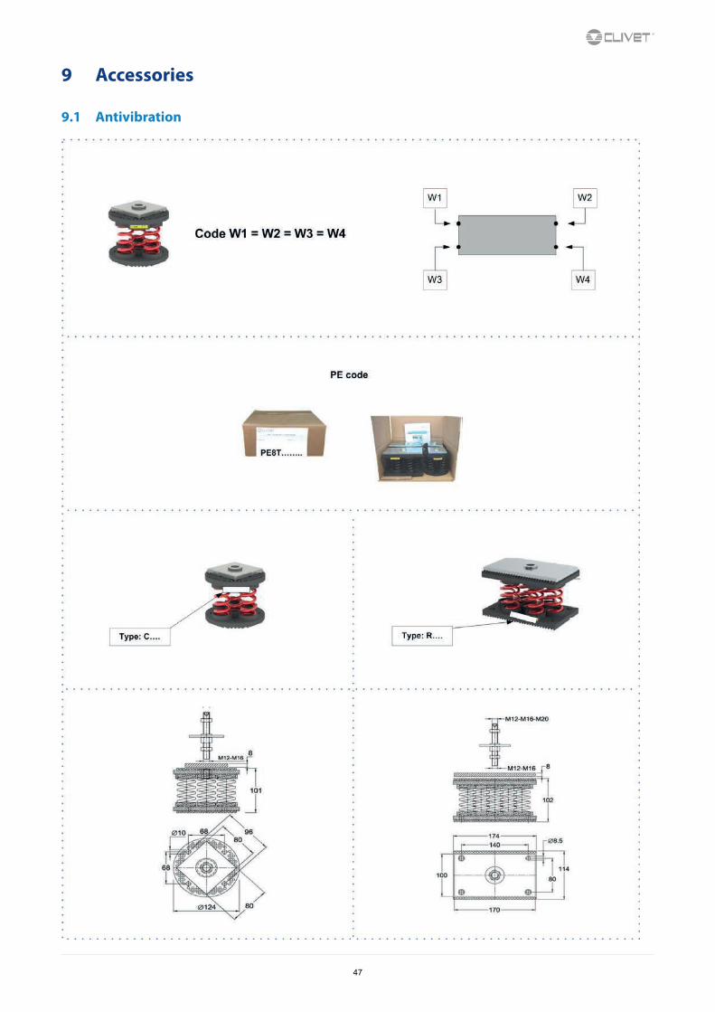
3.4 Anti-vibration mount supportFor details see:9 Accessories p. 47
8

4 Water connections
4.1 Water qualityWater features
• confirming to local regulations
• total hardness < 14°fr
• within the limits indicated by tableThe water quality must be checked by qualified personnel.
Water with inadequate characteristics can cause:
• pressure drop increase
• reduces energy efficiency
• increased corrosion potential
Acceptable water quality values:
SO42-
HCO3-/SO4
2-
Total Hardness
Cl-
PO43-
< 100
> 1
4,5 ÷8,5
< 50
< 2,0
NH3 < 0,5
PH 7,5 ÷9,0
ppm
dH
ppm
ppm
ppm
Fe3+
Mn++
CO2
H2S
Temperature
< 0,5
< 0,05
< 50
< 50
< 65
Oxygen content < 0,1
Free Chlorine < 0,5
ppm
ppm
ppb
°C
ppm
ppm
ppm
Provide a water treatment system if values fall outside the limits.
The warranty does not cover damages caused by limestone formations, deposits and impurities from the water supply and / or failure from failed system clearing to clean system.
4.2 Risk of freezingIf the unit or the relative water connections are subject to temperatures close to 0°C:
• mix water with glycol, or
• safeguard the pipes with heating cables placed under the insulation, or
• empty the system in cases of long non-use
4.3 Anti-freeze solutionThe use of an anti-freeze solution results in an increase in pressure drop.
Make sure that the glycol type utilized is inhibited (not corrosive) and compatible with the water circuit components.
Do not use different glicol mixture (i.e. ethylene with propylene).
4.4 Water flow-rateThe project water-flow must be:
• inside the exchanger operating limits (see the TECHNICAL INFORMATION section)
• guarantee, also with variable system conditions (for example in systems where some circuits are bypassed in particular situations).
4.5 Minimum system water contentMinimum system water volumes are described within ‘General technical data’ section and they have to be satisfied to avoid continuous compressor switching on and off.
9

4.6 Hydronic unit diagrams - Hot only unit
4.7 Hydraulic connections
UNIT
A
filettare – to threadsaldare – to weld
A1 A2
impianto - system
A + B : fornito da Clivet - Clivet supplied
o - or
B
A
Do not weld the system pipe with the Victaulic connection joint attached.
The rubber gasket might be irreparably damaged.
10
USER SIDE/HOT
Standardunit (Std)
Unitwith VARYFLOW +
(VARYH)
Unitwith 1 ON/OFF pump
(HYGH1)
Unitwith 2 ON/OFF pumps
(HYGH2)
Unit with Hydropack
(2PMH)
SOURCE SIDE/COLD
Unit with Hydropack
(2PMC)
Unitwith 2-way modulating valve
(VS2MC)
Unit with 2-way modulating valve for high DP (V2MCP)
Functionalities Diagram hydronic assemblies - Heating only unit
SOURCE SIDE/COLD
Standardunit (Std)
Unitwith VARYFLOW +
(VARYC)
Unitwith 1 ON/OFF pump
(HYGC1)
Unitwith 2 ON/OFF pumps
(HYGC2)

4.8 Hydronic unit diagrams - Cold only unit
4.9 Flow SwitchThe flow switch must be present to ensure shutdown of the unit if water is not circulating.
It has to be installed in a duct rectilinear part, not in proximity of curves that cause turbulences.
Electrically connect the flow switch at the inlet arranged on the XC terminal block.
The flow switch must be set to the minimum reachable flow rate.
A !A
A > 5 x Ø
Ø
B < A
A. minimum distance
11
USER SIDE/ COLD
Standardunit (Std)
Unitwith VARYFLOW +
(VARYC)
Unitwith 1 ON/OFF pump
(HYGC1)
Unitwith 2 ON/OFF pumps
(HYGC2)
Unit with Hydropack
(2PMC)
SOURCE SIDE/HOT
Unit with Hydropack
(2PMH)
Unitwith 2-way modulating valve
(VS2MH)
Unit with 2-way modulating valve for high DP (V2MHP)
Functionalities Diagram hydronic assemblies - Cooling only unit
SOURCE SIDE/HOT
Standardunit (Std)
Unitwith VARYFLOW +
(VARYH)
Unitwith 1 ON/OFF pump
(HYGH1)
Unitwith 2 ON/OFF pumps
(HYGH2)

4.10 Recommended connection
The installer must define:
• component type
• position in system
Examples:
PDTT
PDTT
F
UN
ITC
US
TOM
ER
UN
IT
1
F
6
7
12
8
OP
TIO
N
3
11
9
5
10
CU
STO
ME
R
PDTT
F
UN
ITC
US
TOM
ER
13
14
15
16
18
19
17
OP
TIO
N
Standard unit Unit with 2 pumps Unit with VARIFLOW +
6
7
12
8
11
9
10
6
7
12
8
11
9
10
18
19
13
14
15
16
17
1
3
5
1
3
5
19
1 exchanger 11 drain3 water temperature probe 12 Flow Switch5 differential pressure switch 13 System load safety pressure switch6 antivibration joints 14 pressure gauge7 piping support 15 non-return valve8 exchanger chemical cleaning bypass 16 Pump9 Cleaning system bypass 17 safety valve10 vent 18 shut-off valve
19 filter
12

4.11 Water filterUse filter with mesh pitch:
1,6 mm
It must be installed immediately in the water input of the unit, in a position that is easily accessible for cleaning.
The filter never should be removed, this operation invalidates the guaranty.
4.12 Operation sequenceClose all vent valves in the high points of the unit hydraulic circuit
Close all drain valves in the low points of the unit hydraulic circuit:
• Heat exchangers
• Pumps
• collectors
1. Carefully wash the system with clean water: fill and drain the system several times.
2. Apply additives to prevent corrosion, fouling, formation of mud and algae.
3. Fill the plant
4. Execute leakage test.
5. Isolate the pipes to avoid heat dispersions and formation of condensate.
6. Leave various point of service free (wells, vent-holes etc).
Neglecting the washing will lead to several filter cleaning interventions and at worst cases can cause damages to the exchangers and the other parts.
4.13 Partial energy recoveryOptionA configuration which enables the production of hot water free-of-charge while operating in the cooling mode, thanks to the partial recovery of condensation heat that would otherwise be rejected to the external heat source.
The maximum capacity available from the partial recovery is equal to the 15% of the rejected heating capacity (cooling capacity + compressor power input)
The recovery exchanger must be always maintained full of water
The lack of water amplifies the noise generated by the operation
When the temperature of the water to be heated is particularly low, it is wise to insert a flow-rate control valve into the system water circuit, in order to maintain the temperature at the recovery output at above 35°C and thus avoid the condensation of the refrigerant into the partial energy recovery device.
UNIT
QAB QB
QB
QA
QABVM
OUT 2 1/2"
IN 2 1/2"
120.4 - 240.4
519
1541
13

4.14 Modulating 2-way valve - Provided by the customer (OCO heat only unit)Option
4.15 Modulating 2-way valve - Provided by the customer (OHO heat only unit)Option
* If the system has a lot of inertia in the running of the water flow it is possible to increase the bypass time.
* If the system has a lot of inertia in the running of the water flow it is possible to increase the bypass time.
14

4.16 Modulating 2-way valve - Provided by the customer (OCO cold only unit)Option
4.17 Modulating 2-way valve - Provided by the customer (OHO heat only unit)Option
* If the system has a lot of inertia in the running of the water flow it is possible to increase the bypass time.
* If the system has a lot of inertia in the running of the water flow it is possible to increase the bypass time.
15

4.18 Inverter pump on user side - Provided by the customer (OCO cold only unit)Option
* Check that the minimum operating frequency of the pump is respected, if necessary act on parameter 485 or on the minimum frequency of the inverter itself.** If the system has a lot of inertia in the running of the water flow it is possible to increase the bypass time.
4.19 Inverter pump on source side - Provided by the customer (OHO heat only unit)Option
* Check that the minimum operating frequency of the pump is respected, if necessary act on parameter 505 or on the minimum frequency of the inverter itself.** If the system has a lot of inertia in the running of the water flow it is possible to increase the bypass time.
4.20 NATURAL COOLING functionFor details see:9.2 NATURAL COOLING function p. 49
16

5 Electrical connectionsThe characteristics of the electrical lines must be determined by qualified electrica personnel able to design electrical installations; moreover, the lines must be in conformity with regulations in force.
The protection devices of the unit power line must be able to stop all short circuit current, the value must be determined in accordance with system features.
The power cables and the protection cable section must be defined in accordance with the characteristics of the protections adopted.
All electrical operations should be performed by trained personnel having the necessary qualifications required by the regulations in force and being informed about the risks relevant to these activities.
Operate in compliance with safety regulations in force.
5.1 Electrical dataThe serial number label reports the unit specific electrical data, included any electrical accessories.
The electrical data indicated in the technical bulletin and in the manual refer to the standard unit, accessories excluded.
The matriculation plate shows the indications foreseen by the standards, in particular:
• Voltage
• F.L.A.: full load ampere, absorbed current at maximum admitted conditions
• F.L.I.: full load input, full load power input at max. admissible condition
• Electrical wiringdiagram Nr.
5.2 Connections1. Refer to the unit electrical diagram (the number of the diagram is shown on the serial number label).
2. Verify that the electrical supply has characteristics conforming to the data shown on the serial number label.
3. Before starting work, ensure the unit is isolated, unable to be turned on and a safety sign used.
4. Ensure correct earth connection.
5. Ensure cables are suitably protected.
6. Before powering up the unit, make sure that all the protections that were removed during the electrical connection work have beenrestored.
5.3 Signals / data linesDo not exceed the maximum power allowed, which varies, according to the type of signal.
Lay the cables far from power cables or cables having a different tension and that are able to emit electromagnetic disturbances.
Do not lay the cable near devices which can generate electromagnetic interferences.
Do not lay the cables parallel to other cables, cable crossings are possible, only if laid at 90°.
Connect the screen to the ground, only if there aren’t disturbances.
Guarantee the continuity of the screen during the entire extension of the cable.
Respect impendency, capacity and attenuation indications.
5.4 Power inputFix the cables: if vacated may be subject to tearing.
The cable must not touch the compressor and the refrigerant piping (they reach high temparatures).
17

5.5 Connections performer by customer
ALM KMP evaporator pump contactorAPV KMRI heaters contactorAP18 KMS condenser pump contactorAP19 QMP motor protection switch evaporator pumpAPRI QMS motor protection switch condenser pumpAPSI SA1 remote on/offAPUI SA1.1 second setpointBT7 SA6 sanitary hot water cycle switchHLC1-4 SA7 summer-winter switchHLR SA9 cooling thermostat
YVHS1 SQ1 Flow SwitchYWMC SQ2 Condenser flow switchYWMH
cumulative fault signal0..10V analogical outputDemand limitwater reset0..10V signal heaters0..10V signal heating side inverter *0..10V signal cooling side inverter *Probe of the outdoor air temperature. compressor status signalalarm signal lamp electrical heater electrical panel selectorsanitary hot water valvemodulating valve cooling sidemodulating valve heating side
* The APSI and APUI signal can be used to control a single inverter, the control of multiple inverter in parallel is not allowed.
18

5.6 Power supply cables section / power barsSize 70.4 75.4 80.4 85.4 90.4 100.4 110.4
Min. cable section Cu (mm²) 1x95 1x95 1x95 1x95 1x95 1x95 1x95
Max. cable section Cu (mm²) 1x150 1x150 1x150 1x150 1x185 1x185 1x185
Min. bar Cu section (mm²) - - - - - - -
Max. bar Cu width (mm) 32 32 32 32 32 32 32
Tightening torque (Nm) 20 20 20 20 20 20 20
Size 120.4 140.4 160.4 180.4 200.4 220.4 240.4
Min. cable section Cu (mm²) 1x150 1x150 1x240 1x240 2x150 2x150 2x150
Max. cable section Cu (mm²) 1x240 1x240 1x240 1x240 2x300 2x300 2x300
Min. bar Cu section (mm²) - - - - 2 x 30 x 5 2 x 30 x 5 2 x 30 x 5
Max. bar Cu width (mm) 32 32 40 40 50 50 50
Tightening torque (Nm) 20 20 20 20 20 20 20
5.7 Remote ON-OFFDo not perform short On Off cycles
Do not use the remote On Off with thermoregulation function.
A BA B
Y E S N O !
A
B
AB
19

5.8 Computer connection
1. Service keypad
2. RJ45: standard connection
3. P.C.-not supplied
4. P.C. connection, shift RJ45 from T-HI to T-IP
Configure P.C.
1. connect P.C. and main module with LAN cable
2. check in the taskbar that the connection is active
3. open Control Panel and select Network and sharing center
4. select Modify board setting
5. select Local area connection (LAN)
6. select Internet protocol version 4 (TPC) IPV4 and enter Property
7. set the IP address 192.168.1.100
8. set Subnet mask as 255.255.255.0
9. confirm (OK)
10. enter Start (Windows button)
11. write the command cmd and enter/do it
12. write and run the command Ping 192.168.1.42
13. the message, connection is OK, will appear when successful
14. enter the browser (Crhome, Firefox ecc)
15. write and run the command http:/192.168.1.42
16. Userid = WEB
17. Password = SBTAdmin!
20

5.9 Remote controlOption
1 Distance up to 350 mt A User interface2 Distance up to 700 mt B = B1 KNX bus, max 350 mt
twisted pair with shield, ø 0,8 mmEIB/KNX cable marking recommende
C PSX - Mains power supply unitpwer supply unit N125/11 5WG1 125-1AB11
C1 AC 120...230V, 50...60HzD KNX bus, max 350 mt
21

5.10 Modbus - RS485Option
LED BSP communication with AP1 module LED BUS communication with Modbusgreen communication ok green communication okyellow software ok but communication with AP1
downyellow startup / channel not communicating
red flashing: software error red communication downfixed: hardware error
A. Unit
B. Metal conduit
C. Metal septums
D. Metal-lined sheath (sleeve)
Modbus / LonWorks / Cable requirementsCouple of conductors twisted and shielded
Section of conductor 0,22mm2…0,35mm2
Rated power between conductors < 50 pF/m
Nominal impedance 120 Ω
Recommended cable BELDEN 3106A
• Every RS485 serial line must be set up using the ‘In/Out’ bus system.
• Other types of networks are not allowed, such as Star or Ring networks.
• The difference in potential between the earth of the two RS485 devices that the cable shielding needs to be connected to must be lower than 7 V
• There must be suitable arresters to protect the serial lines from the effects of atmospheric discharges
• A 120 ohm resistance must be located on the end of the serial line. Alternatively, when the last serial board is equipped with an internal terminator, it must be enabled using the specific jumper, dip switch or link.
• The cable must have insulation features and non-flame propagation in accordance with applicable regulations.
• The RS485 serial line must be kept as far away as possible from sources of electromagnetic interference.
22

5.11 LonWorksOption
LED BSP communication with AP1 module LED BUS communication with LonWorksgreen communication ok green ready for communicationyellow software ok but communication with AP1
downyellow startup
red flashing: software error red flashing: communicating not possiblefixed: hardware error communication down
5.12 BACnet IPOption
LED BSP communication with AP1 module LED BUS communication with BACnetgreen communication ok green ready for communicationyellow software ok but communication with AP1
downyellow startup
red flashing: software error red BACnet server downfixed: hardware error restart after 3 sec
23

6 Start-up
6.1 General descriptionThe indicated operations should be done by qualified technician with specific training on the product.
The electrical, water connections and the other system works are by the installer.
Upon request, the service centres performing the start-up.
Agree upon in advance the star-up data with the service centre.
For details refer to the different manual sections.
Before checking, please verify the following:
• the unit should be installed properly and in conformity with this manual
• the electrical power supply line should be isolated at the beginning
• the unit isolator is open, locked and equipped with the suitable warning
• make sure no tension is present
After turning off the power, wait at least 5 minutes before accessing to the electrical panel or any other electrical component.
Before accessing check with a multimeter that there are no residual stresses.
6.2 Preliminary checks
Unit OFF power supply1. safety access
2. functional spaces
3. structure integrity
4. unit on vibration isolators
5. unit input water filter + shut-off valves for cleaning
6. vibration isolators on water connections
7. expansion tank (indicative volume = 5% system content)
8. minimum system water content
9. cleaned system
10. loaded system + possible glycol solution + corrosion inhibitor
11. system under pressure
12. vented system
13. refrigerant circuit visual check
14. earthing connection
15. power supply features
16. electrical connections provided by the customer
6.3 Start-up sequenceUnit ON power supply
1. compressor crankcase heaters operating at least since 8 hours
2. off-load voltage measure
3. phase sequence check
4. pump manual start-up and flow check
5. shut-off valve refrigerant circuit open
6. unit ON
7. load voltage measure and absorptions
8. liquid sight glass check (no bubbles)
9. measure return and supply water temperature
10. measure super-heating and sub-cooling
11. check no anomalous vibrations are present
12. climatic curve personalization
13. climatic curve personalization
14. scheduling personalization
15. complete and available unit documentation
24

6.4 Refrigeration circuit1. Check carefully the refrigerating circuit: the presence of oil stains can mean leakage caused by transportation, movements or other).
2. Verify that the refrigerating circuit is in pressure: Using the unit manometers, if present, or service manometers.
3. Make sure that all the service outlets are closed with proper caps; if caps are not present a leak of refrigerant can be possible.
4. Open the valves of the refrigerant circuit, if there are any.
6.5 Water circuit1. Before realizing the unit connection make sure that the hydraulic system has been cleaned up and the cleaning water has been drained.
2. Check that the water circuit has been filled and pressurized.
3. Check that the shut-off valves in the circuit are in the “OPEN” position.
4. Check that there isn’t air in the circuit, if required, evacuate it using the air bleed valve placed in the system high points.
5. When using antifreeze solutions, make sure the glycol percentage is suitable for the type of use envisaged.
Neglecting the washing will lead to several filter cleaning interventions and at worst cases can cause damages to the exchangers and the other parts.
Weight of glycol (%) 10 20 30 40
Freezing temperature (°C) -3.9 -8.9 -15.6 -23.4
Safety temperature (°C) +1 -4 -10 -19
6.6 Electric CircuitVerify that the unit is connected to the ground plant.
Check the conductors are tightened as: the vibrations caused by handling and transport might cause these to come loose.
Connect the unit by closing the sectioning device, but leave it on OFF.
Check the voltage and line frequency values which must be within the limits: 400/3/50 +/- 10%
Check and adjust the phase balance as necessary: it must be lower than 2%
Example
Working outside of these limits can cause irreversible damages and voids the warranty.
6.7 Compressor crankcase heatersConnect the oil resistances on the compressor crankcase at least 8 hours before the compressor is to be starter:
• at the first unit start-up
• after each prolonged period of inactivity
1. Connect the heaters: sectioning device on 1 / ON.
2. To make sure that heaters are working, check the power input.
3. At start-up the compressor crank-case temperature on the lower side must be higher at least of 10°C than the outside temperature.
Do not start the compressor with the crankcase oil below operating temperature.
6.8 Remote controlsCheck that the remote controls (ON-OFF etc) are connected and, if necessary, enabled with the respective parameters as indicated in the “electrical connections” section.
Check that probes and optional components are connected and enabled with the respective parameters (“electrical connections” section and following pages).
25

6.9 VoltagesCheck that the air and water temperatures are within in the operating limits.
Start-up the unit.
With unit operating in stable conditions, check:
• Voltage
• Total absorption of the unit
• Absorption of the single electric loads
6.10 Demand limitMenu accessible only after having entered the password.
Access reserved only to specifically trained personnel.
The parameter modification can cause irreversible damages.
It is possible to limit the absorbed electric power with an external signal 0-10 Vcc.
The higher the signal is, the lower the number of compressors available to meet the thermal need.
If only P0002: EnDemandLimit ≠ 0
Path: Main Menu / Unit parameters / Demand limit
Step Display Action Menu/Variable Keys Notes
1 Press 3 sec.
2 Password Set Password
3 Press
4 Main menu Select Unit parameters
5 Unit parameters Select Set Point
6 Set Point Select Demand limit
7 Set Demand limit
8 Confirm
9 Press 3 sec.
10 Select Local connections
Path: Main Menu / Unit parameters / Demand limit
Parameters Short description Description
P0200 setpointdemandlimit Parameter setting of the value % of demand limit
26

6.11 Climatic TExt
Menu accessible only after having entered the password.
Access reserved only to specifically trained personnel.
The parameter modification can cause irreversible damages.
The setpoint defined by the temperature curve is shown at status S0052: ActualUtSetp
Only if P0036: EnCompExt ≠ 0
Path: Main Menu / Unit parameters / TExt Correction config
Example
P0612P0610
P0613
-5 5 10 15
5
10
15
25
30
P0606
P0609 P0607
18 22 24 26 28 30 32 34
2468
10121416
34 0 25 3020
0
20
T ext. T ext.
setpointsetpoint
Cool ing
P0608
Heat ing
P0611
S0052S0052
20
Step Display Action Menu/Variable Keys Notes
1 Press 3 sec.
2 Password Set Password
3 Press
4 Main menu Select Unit parameters
5 Unit parameters Select Climatic TExt
6 Climatic TExt (pwd) Select Parameter
7 Set
8 Confirm
9 Press 3 sec.
10 Select Local connections
Path: Main Menu / Unit parameters / TExt Correction config
Parameters Short description Description
P0606 CSptLow setpoint temperature value when the air temperature value is AirAtSptLowC
P0607 AirAtSetPointLowC external air temperature value where the calculated setpoint takes on the value given by CSptLow
P0608 CSptHigh setpoint temperature value when the air temperature value is AirAtSptHigC
P0609 AirAtSetPointHighC external air temperature value where the calculated setpoint takes on the value given by CSptHigh
P0610 HSptLow setpoint temperature value when the air temperature value is AirAtSptLowH
P0611 AirAtSptLowH external air temperature value where the calculated setpoint takes on the value given by HSptLow
P0612 HSptHigh setpoint temperature value when the air temperature value is AirAtSptHigH
P0613 AirAtSptHigH external air temperature value where the calculated setpoint takes on the value given by HSptHigh
27

6.12 Water reset
Menu accessible only after having entered the password.
Access reserved only to specifically trained personnel.
The parameter modification can cause irreversible damages.
The water reset correction affects the setpoint defined by the Climate curve TExt (actual setpoint).
The setpoint is shown at status S0052: ActualUtSetp
Only if P0003: En WaterReset ≠ 0
Path: Main menu / Unit parameters / Water reset config
Step Display Action Menu/Variable Keys Notes
1 Press 3 sec.
2 Password Set Password
3 Press
4 Main menu Select Unit parameters
5 Unit parameters Select Water reset
6 Water reset Select Parameter
7 Set
8 Confirm
9 Press 3 sec.
10 Select Local connections
Path: Main Menu / Unit parameters / Water reset
Parameters Short description Description
P0616 MaxCWRC Maximum correction to be applied to the setpoint Cooling
P0617 SWRMaxC Value of the WR control signal corresponding to the correction of the set Cool equal to P0616
P0618 SWRMinC Value of the WR control signal corresponding to the correction of the set COOL equal to 0
P0615 MaxCWRH Maximum correction to be applied to the setpoint Heating
P0619 SWRMaxH Value of the WR control signal corresponding to the correction of the set Heating equal to P0615
P0620 SWRMinH Value of the WR control signal corresponding to the correction of the set Heating equal to 0
P0616 / P0618: CoolingP0615, P0619, P0620: Heating
28

6.13 ECOSHARE function for the automatic management of a group of units
• Max 7 units
• Maximum length of the bus line: 700 m.
• Maximum distance between 2 units: 300 m
• Type of cable: shielded twisted pair cable Ø 0,8 mm. use an EIB/KNX cable
• Possible connections: Tree, star, in/out bus, mixed
• It is not possible to use a ring connection
• No end-of-line resistor or terminator required
• There must be suitable arresters to protect the serial lines from the effects of atmospheric discharges
• The data line must be kept separate from the power conductors or powered at different voltage values and away from possible sources of electrical interference
29

If there are more units connected in a local network set the mode of operation.
MODE AEvery unit manages its own compressors according to the setpoint.
Every unit optimizes its refrigeration circuits.
Pumps always active, even with compressor stoped.
P0658 = 0
P0657 > 0 °C
setpoint1 > setpoint2 > setpoint3
or
setpoint1 < setpoint2 < setpoint3
MODE BThe master manages the single cooling.
The master optimizes individual refrigerant circuits.
Pumps always active, even with compressor stoped.
P0658 = 1
P0657 = 0 °C
setpoint1 = setpoint2 = setpoint3
plus: optimal H2O temperature control
MODE CThe master manages the single cooling.
The master optimizes individual refrigerant circuits.
Active pumps only with active compressors.
P0658 = 2
P0657 = 0 °C
setpoint1 = setpoint2 = setpoint3
plus: minimum pumps consumption need balanced system (t1 = t2 = t3)
Path: Main Menu / Unit parameters / Master Slave
Parameters Short description Description
P0655 LNinstalledUnits Number of network-connected units including the master
P0656 LNStandByUnits Number of units kept in standby
P0657 LNOffset Temperature Offset the master sum or subtract, depending on the way you set, in order of priority, to the set point of the slave
P0658 TypeRegMS Operation mode: 0=mode A; 1=mode B; 2=mode C
P0659 LNAddress ProcessBus address unit
30

6.14 Evaporator water flow-rateCheck that the difference between the temperature of exchanger return and supply water corresponds to power according to this formula:
unit cooling power (kW) x 860 = Dt (°C) x flow rate (L/h)
The cooling power is shown in the table of the GENERAL TECHNICAL DATA included in this manual, referred to specific conditions, or in the tables on COOLING PERFORMANCE in the TECHNICAL BULLETIN referred to various conditions of use.
Check for water side exchanger pressure drops:
determine the water flow rate
measure the difference in pressure between exchanger input and output and compare it with the graph on WATER SIDE EXCHANGER PRESSURE DROPS
The measurement of pressure will be easier if pressure gauges are installed as indicated in the DIAGRAM OF SUGGESTED WATER CONNECTIONS.
6.15 Inverter driven variable flow-rate cooling side control depending on the temperature differentialThis option allows water flow-rate modulation to the unit during partial load conditions, maintaining stable the temperature difference between inlet and outlet to the heat exchanger.
Designed for systems with primary circuit variable flow-rate systems decoupled from secondary circuit. With no building load the unit switches off the compressors while concerning pumps is possible to select:
• active pumps with minimum flow-rate, monitoring secondary circuit temperature variations (par. P0079 EnQVarUtil = 2; par. P0080DelayPeriodUt = < 60 sec)
• Pump switching off, periodically activating them (settable time par P0080 DelayPeriodUt) leading secondary circuit temperatures onprimary circuit (par. P0079 EnQVarUtil = 0)
• Pump switching off and waiting for the user signal for activation (free potential; par. P0079 EnQVarUtil = 0)
Flow-rate modulation is managed by embedded logic thanks to built-in flow-rate control device and temperature probes. This device is installed and wired.
This option is available only with inverter driven HYDROPACK selected (2PMV / 3PMV)
6.16 Scroll compressorThe Scroll compressors have only one rotation direction.
In the event it is reversed, the compressor is not immediately damaged, but increases its noise and jeopardises pumping.
After a few minutes, the compressor blocks due to intervention of the thermal protection.
In this case, disconnect power supply and invert 2 phases on the machine power supply.
Avoid the compressor working for a long time with contrary rotation: more than 2-3 of these anomalous start-ups can damage it.
To ensure the rotation direction is correct, measure the condensation and suction pressure.
The pressures must significantly differ: upon start-up, the suction pressure decreases whereas the condensation one, increases.
6.17 Operating at reduced loadThe units are equipped with partialization steps and they can, therefore, operate with reduced loads.
However a constant and long operation with reduced load with frequent stop and start-up of the compressor/s can cause serious damages for the lack of oil return.
The above-described operating conditions must be considered outside the operating limits.
In the event of compressor breakdown, due to operating in the above-mentioned conditions, the guarantee will not be valid and Clivet spa declines any responsibility.
Check periodically the average operating times and the frequency of the compressors starts: approximately the minimum thermal load should be such as to need the operating of a compressor for at least ten minutes.
If the average times are close to this limit, take the proper corrective actions.
6.18 Start-up reportIdentifying the operating objective conditions is useful to control the unit over time.
With unit at steady state, i.e. in stable and close-to-work conditions, identify the following data:
• total voltages and absorptions with unit at full load
• absorptions of the different electric loads (compressors, fans, pumps etc)
• temperatures and flows of the different fluids (water, air) both in input and in output from the unit
• temperature and pressures on the characteristic points of the refrigerating circuit (compressor discharge, liquid, intake)
The measurements must be kept and made available during maintenance interventions.
31

6.19 2014/68/UE PED directiveDIRECTIVE 2014/68/UE PED gives instructions for installers, users and maintenance technicians as well.
Refer to local regulations; briefly and as an example, see the following:
Compulsory verification of the first installation:
• only for units assembled on the installer’s building site (for ex. Condensing circuit + direct expansion unit)
Certification of setting in service:
• for all the units
Periodical verifications:
• to be executed with the frequency indicated by the Manufacturer (see the “maintenance inspections” paragraph)
32

7 Control
7.1 LedINFO Not used
ALARM Blink / fixed = alarm present
CANCEL not used currently
Heat: Heating (not used)
7.2 DisplayRef. Variable Description
A Date - Time
B ActualSetPoint Temperature setting
C T.InH2OUtilitySide Water inlet temperature utility side
D T.OutH2OUtilitySide Water outlet temperature utility side
E ActualState On / off / eco / pmp On
F ActualMode Cool: water coolingHeat: HEATING
2 Installed compressors
1 - 0Compressors ONexample: circuit 1 = 1 compr. Oncircuit 2 = 0 compr. On
50% Heating capacity
7.3 KeysSymbol Name Description
Info Main menu
Alarm Alarm display
CancelExitPrevious levelKeyboard settings
Up Increases value
Down Decreases value
Enter ConfirmPassword
33

7.4 Change unit state
Step Display Action Menu/Variable Keys Notes
1 Press
2 Main menu Select Cmd Local state
3 Set OFF - ECO - ON - Pump On *
4 Confirm
6 Exit
* Local state
ECO: recurrent pump ON-OFF; compressors keep water system at setpoint ECO
Pmp ON: pump ON, compressor OFF
7.5 Change the modeStep Display Action Menu/Variable Keys Notes
1 Press
2 Main menu Select Cmd Local mode
3 Set Cool: water coolingHeat: HEATING
4 Confirm
5 Exit
7.6 Modify setpointStep Display Action Menu/Variable Keys Notes
1 Press
2 Main menu Select Unit parameters
3 Unit parameters Confirm Set Point
4 Select Set Point
5 Set Set Point
6 Confirm
7 Exit
Parameters Short description Description
P0583 SetPointCooling Setpoint Cool
P0584 2SetPointCooling 2° Setpoint Cool Enable by remote switch
P0855 SetPointECOCooling Economic summer SetPoint
P0577 SetPointHeating Setpoint Heat
P0578 2SetPointHeating 2° Setpoint Heat
P0579 SetPointECOHeating Economic winter SetPoint
P0640 SetPointRecover Recovery Set Point
P0580 ACSSetPoint domestic hot water set point
34

7.7 SchedulerIt is possible to set 6 events (Off, Eco, On, Recirculating) for each week day.
Step Display Action Menu/Variable Keys Notes
1 Press
2 Main menu Select Scheduler
3 Scheduler Select Day
4 Select Time
5 Set Event time
6 Confirm
7 Select Value
8 Set On/Eco..
9 Confirm
10 Exit
Enable Scheduler
Step Display Action Menu/Variable Keys Notes
1 Press 3 sec.
2 Password Set Password
3 Press *
4 Main menu Select Unit Parameters
5 Select Option config
6 Set P0052=1
7 Press 3 sec.
Select Local connections
* Unit Parameters menu is displayed
7.8 Display the statusStep Display Action Menu/Variable Keys Notes
1 Press
2 Main menu Select Machine State
3 Select General, circuit, ecc..
4 Exit
35

7.9 Keyboard settingsStep Display Action Menu/Variable Keys Notes
1 Press 3 sec.
2 Press
3 HMI Settings Select
4 Press
5 Press
6 Select Local connections
7.10 AlarmsBefore resetting an alarm identify and remove its cause.
Repeated resets can cause irreversible damage.
Example:
+ eE0001: Phase monitor: Fault = active alarm
- EE0003: Pum 1 faulty: Ok = resetted alarm
Display of alarm: step 1-3
Reset allarm: step 4-10
Step Display Action Menu/Variable Keys Notes
1 Press
2 Alarm list detail Press
3 Alarm list Select Alarm
4 Alarm list detail Press 3 sec.
5 Password Set Enter password
6 Alarm list detail Press
7 Alarm list Select Alarm
8 Select ResetExecuted
9 Press 3 sec.
10 Password management Select Log off
For details see:
General list of alarms
36

7.11 General list of alarms
ELECTRICAL CIRCUIT ALARMS Num Name Description Category
eE0001 Phase monitor Phase monitor fault Central
EE0003 Pump 1 faulty User side pump 1 overload protection GP Ut
EE0004 Pump 2 faulty User side pump 2 overload protection GP Ut
EE0005 Pump 3 faulty User side pump 3 overload protection GP Ut
eE0008 Utility Inverter Protection User side inverter overload protection GP Ut
ee0010 Master Offline Master unit offline MS
ee0011 Unit 2 in alarm 2nd slave unit fault MS
ee0012 Unit 2 OffLine 2nd slave unit offline MS
ee0013 Unit 3 in alarm 3rd slave unit fault MS
ee0014 Unit 3 OffLine 3rd slave unit offline MS
ee0015 Unit 4 in alarm 4th slave unit fault MS
ee0016 Unit 4 OffLine 4th slave unit offline MS
ee0017 Unit 5 in alarm 5th slave unit fault MS
ee0018 Unit 5 OffLine 5th slave unit offline MS
ee0019 Unit 6 in alarm 6th slave unit fault MS
ee0020 Unit 6 OffLine 6th slave unit offline MS
ee0021 Unit 7 in alarm 7th slave unit fault MS
ee0022 Unit 7 OffLine 7th slave unit offline MS
ee0027 Utility Water In temp Error User side in water temperature probe fault Central
ee0028 Utility Water Out temp Error User side out water temperature probe fault Central
ee0029 Temp Ext Sensor Error External air temperature probe fault HW
ee0030 DemandLimit Demand limit fault HW
ee0031 WaterReset Water reset fault HW
ee0032 External Humidity probe Error Relative humidity probe fault HW
ee0033 T.Quadro Ele Electrical panel temperature probe fault HW
ee0035 YV Cool Open YV Cool opening fault 4P
ee0036 YV Heat Open YV Heat opening fault 4P
ee0037 YV Cool Close YV Cool closing fault 4P
ee0038 YV Heat Close YV Heat closing fault 4P
ee0040 FCI Water Temp. Freecoling water temperature probe fault HW FCI
EE0044 Pump 1 Allarm Freecooling pump 1 overload protection FCI Circuit 1
EE0045 Pump 2 Allarm Freecooling pump 2 overload protection FCI Circuit 1
EE0046 Pump 3 Allarm Freecooling pump 3 overload protection FCI Circuit 1
ee0047 Pump Change for Utility Flow Switching pump on user side for flow alarm GP User side
ee0050 P.DifferenzialeUtil User side differential pressure sensore fault HW
EE0054 Recovery Pump 1 protection Recovery side pump 1 overload protection Recovery
EE0055 Recovery Pump 2 protection Recovery side pump 2 overload protection Recovery
EE0056 Recovery Pump 3 protection Recovery side pump 3 overload protection Recovery
eE0057 Recovery Inverter Protection Recovery side inverter overload protection Recovery
ee0100 TimeOutModPOL98U 1st POL98U module disconnected HW TimeOut
ee0101 TimeOutModPOL98U_2 2nd POL98U module disconnected HW TimeOut
ee0102 TimeOutModPOL96U POL96U module disconnected HW TimeOut
ee0103 TimeOutModPOL945 POL945 module disconnected HW TimeOut
37

ELECTRICAL CIRCUIT ALARMS Num Name Description Category
ee0104 TimeOutModPOL965 POL965 module disconnected HW TimeOut
ee0105 TimeOutModPOL94U 1st POL94U module disconnected HW TimeOut
ee0106 TimeOutModPOL94U_2 2nd POL94U module disconnected HW TimeOut
ee0107 TimeOutModPOL985 POL985 module disconnected HW TimeOut
ee1001 T.Suction Gas Gas temperature probe 3 fault HW Circuit 1
ee1002 T.Suction Gas Gas temperature probe 5 fault HW Circuit 1
ee1003 P.Suction Heat Pressure sensor fault, low pressure heating HW Circuit 1
ee1004 EEV1 blocked EEV 1 blocked Circuit 1
ee1005 EEV1 blocked EEV2 blocked Circuit 1
EE1006 Comp 1 protections Compressor 1 overload protection Circuit 1
EE1007 Comp 2 protections Compressor 2 overload protection Circuit 1
EE1008 Comp 3 protections Compressor 3 overload protection Circuit 1
EE1009 Source Inverter Protection Source side inverter overload protection Source 1
ee1010 Pump Change for Source Flow Switching pump on source side for flow alarm Source 1
EE1013 Source Pump 1 protection Source side pump 1 overload protection Source 1
EE1014 Source Pump 2 protection Source side pump 2 overload protection Source 1
EE1015 Source Pump 3 protection Source side pump 3 overload protection Source 1
EE1018 Source side protection Source side ventilation overload protection Circuit 1
ee1022 T.Discharge C1.1 Compressor 1 discharge temperature probe fault HW Circuit 1
ee1023 T.Discharge C2.1 Compressor 2 discharge temperature probe fault HW Circuit 1
ee1024 T.Discharge C3.1 Compressor 3 discharge temperature probe fault HW Circuit 1
ee1025 T.Source 1 Source 1 temperature probe fault HW Circuit 1
ee1026 T.Source 2 Source 2 temperature probe fault HW Circuit 1
ee1027 T.Suction Gas Suction temperature probe fault HW Circuit 1
ee1028 P.Discharge High pressure probe fault HW Circuit 1
ee1029 P.Suction Low pressure probe fault HW Circuit 1
ee1030 T.GasRecovery Recovery exchanger gas temperature probe fault HW Circuit 1
ee1031 P.GasRecovery Recovery exchanger gas pressure probe fault HW Circuit 1
ee1032 T.Ing Recovery Recovery in temperature probe fault HW Circuit 1
ee1033 T.Out Recovery Recovery out temperature probe fault HW Circuit 1
ee1037 Alarm Inverter 1 Inverter 1 in alarm Inverter APY
ee1038 Alarm missing comunication inv1 Inverter 1 Modbus communication error Inverter APY
ee1039 Timeout comunication inv1 Inverter 1 communication timeout Inverter APY
ee1040 Alarm Inverter 2 Inverter 2 in alarm Inverter APY
ee1041 Alarm missing comunication inv2 Inverter 2 Modbus communication error Inverter APY
ee1042 Timeout comunication inv2 Inverter 2 communication timeout Inverter APY
ee1043 Alarm Inverter 3 Inverter 3 in alarm Inverter APY
ee1044 Alarm missing comunication inv3 Inverter 3 Modbus communication error Inverter APY
ee1045 Timeout comunication inv3 Inverter 3 communication timeout Inverter APY
EE1047 Alarm Envelop Comp1 Compressor 1 envelope alarm Circuit 1
EE1048 Alarm Envelop Comp2 Compressor 2 envelope alarm Circuit 1
EE1049 Alarm Envelop Comp3 Compressor 3 envelope alarm Circuit 1
ee1055 Alarm Inverter 1 Inverter 1 in alarm Inverter DFS
ee1056 Alarm missing comunication inv1 Inverter 1 Modbus communication error Inverter DFS
ee1057 Timeout comunication inv1 Inverter 1 communication timeout Inverter DFS
38

ELECTRICAL CIRCUIT ALARMS Num Name Description Category
ee1058 Alarm Inverter 2 Inverter 2 in alarm Inverter DFS
ee1059 Alarm missing comunication inv2 Inverter 2 Modbus communication error Inverter DFS
ee1060 Timeout comunication inv2 Inverter 2 communication timeout Inverter DFS
ee1061 Alarm Inverter 3 Inverter 3 in alarm Inverter DFS
ee1062 Alarm missing comunication inv3 Inverter 3 Modbus communication error Inverter DFS
ee1063 Timeout comunication inv3 Inverter 3 communication timeout Inverter DFS
ee1070 User side ECV 1.1 User side ECV connection problem HW Circuit 1
ee1071 Source ECV 1.1 Source side ECV 1 connection problem HW Circuit 1
ee1072 Source ECV 2.1 Source side ECV 2 connection problem HW Circuit 1
ee2001 T.Suction Gas Gas temperature probe 4 fault HW Circuit 2
ee2002 T.Suction Gas Gas temperature probe 6 fault HW Circuit 2
ee2003 P.Suction Heat Pressure sensor fault, low pressure heating HW Circuit 2
ee2004 EEV1 blocked EEV1 blocked Circuit 2
ee2005 EEV1 blocked EEV2 blocked Circuit 2
EE2006 Comp 1 protections Compressor 1 overload protection Circuit 2
EE2007 Comp 2 protections Compressor 2 overload protection Circuit 2
EE2008 Comp 3 protections Compressor 3 overload protection Circuit 2
EE2009 Source Inverter Protection Source side inverter overload protection Source 2
ee2010 Pump Change for Source Flow Switching pump on source side for flow alarm Source 2
EE2013 Source Pump 1 protection Source side pump 1 overload protection Source 2
EE2014 Source Pump 2 protection Source side pump 2 overload protection Source 2
EE2015 Source Pump 3 protection Source side pump 3 overload protection Source 2
EE2018 Source side protection Source side ventilation overload protection Circuit 2
ee2022 T.Discharge C1.1 Compressor 1 discharge temperature probe fault HW Circuit 2
ee2023 T.Discharge C2.1 Compressor 2 discharge temperature probe fault HW Circuit 2
ee2024 T.Discharge C3.1 Compressor 3 discharge temperature probe fault HW Circuit 2
ee2025 T.Source 1 Source 1 temperature probe fault HW Circuit 2
ee2026 T.Source 2 Source 2 temperature probe fault HW Circuit 2
ee2027 T.Suction Gas Suction gas temperature probe fault HW Circuit 2
ee2028 P.Discharge High pressure probe fault HW Circuit 2
ee2029 P.Suction Low pressure probe fault HW Circuit 2
ee2030 T.GasRecovery Recovery exchanger gas temperature probe fault HW Circuit 2
ee2031 P.GasRecovery Recovery exchanger gas pressure probe fault HW Circuit 2
ee2032 T.Ing Recovery Recovery in temperature probe fault HW Circuit 2
ee2033 T.Out Recovery Recovery out temperature probe fault HW Circuit 2
ee2037 Alarm Inverter 1 Inverter 1 in alarm Inverter APY
ee2038 Alarm missing comunication inv1 Inverter 1 Modbus communication error Inverter APY
ee2039 Timeout comunication inv1 Inverter 1 communication timeout Inverter APY
ee2040 Alarm Inverter 2 Inverter 2 in alarm Inverter APY
ee2041 Alarm missing comunication inv2 Inverter 2 Modbus communication error Inverter APY
ee2042 Timeout comunication inv2 Inverter 2 communication timeout Inverter APY
39

ELECTRICAL CIRCUIT ALARMS Num Name Description Category
ee2043 Alarm Inverter 3 Inverter 3 in alarm Inverter APY
ee2044 Alarm missing comunication inv3 Inverter 3 Modbus communication error Inverter APY
ee2045 Timeout comunication inv3 Inverter 3 communication timeout Inverter APY
EE2047 Alarm Envelop Comp1 Compressor 1 envelope alarm Circuit 2
EE2048 Alarm Envelop Comp2 Compressor 2 envelope alarm Circuit 2
EE2049 Alarm Envelop Comp3 Compressor 3 envelope alarm Circuit 2
ee2055 Alarm Inverter 1 Inverter 1 in alarm Inverter DFS
ee2056 Alarm missing comunication inv1 Inverter 1 Modbus communication error Inverter DFS
ee2057 Timeout comunication inv1 Inverter 1 communication timeout Inverter DFS
ee2058 Alarm Inverter 2 Inverter 2 in alarm Inverter DFS
ee2059 Alarm missing comunication inv2 Inverter 2 Modbus communication error Inverter DFS
ee2060 Timeout comunication inv2 Inverter 2 communication timeout Inverter DFS
ee2061 Alarm Inverter 3 Inverter 3 in alarm Inverter DFS
ee2062 Alarm missing comunication inv3 Inverter 3 Modbus communication error Inverter DFS
ee2063 Timeout comunication inv3 Inverter 3 communication timeout Inverter DFS
ee2070 User side ECV 1.1 User side ECV connection problem HW Circuit 2
ee2071 Source ECV 1.1 Source side ECV 1 connection problem HW Circuit 2
ee2072 Source ECV 2.1 Source side ECV 2 connection problem HW Circuit 2
REFRIGERANT CIRCUIT ALARMS
Num Name Description Category
ff1005 Min overheating EEV1 Value of refrigerant superheat too low EEV1 (user side) Circuit 1
ff1006 Min overheating EEV2 Value of refrigerant superheat too low EEV1 (source) Circuit 1
fF1009 Low Pressure Alarm (DI) Low Pressure Alarm (DI) Circuit 1
ff1010 Warning LP Cool Low Pressure Pre Alarm in Cooling Mode Circuit 1
ff1011 Warning LP Heat Low Pressure Pre Alarm in Heating Mode Circuit 1
fF1012 Low pressure Alarm Heat (AI) Low Pressure in Heating Mode (AI) Circuit 1
fF1013 High Pressure (DI) High Pressure Alarm (DI) Circuit 1
ff1014 Warning High Pressure High Pressure Pre Alarm Circuit 1
fF1015 High Pressure Alarm (AI) High Pressure Alarm (AI) Circuit 1
ff1016 Max RC Warning Maximum Pressure Ratio Pre Alarm Circuit 1
fF1017 Min RC Alarm Minimum Pressure Ratio Pre Alarm Circuit 1
fF1018 Low Pressure Alarm Cool(AI) Low Pressure Alarm in Cooling Mode Circuit 1
FF1019 Max RC Alarm Maximum Pressure Ratio Circuit 1
FF1034 Vacuum Circuit Vaacum Alarm Circuit 1
FF1046 LimLp Low pressure limit Circuit 1
ff1047 DFRForced Defrost Forced Circuit 1
ff1048 DFRWaterTLow Low water temperature for defrost operation Circuit 1
ff1049 DFRTimeMax Defrost Maximum Time Circuit 1
40

REFRIGERANT CIRCUIT ALARMS
Num Name Description Category
ff2005 Min overheating EEV1 Min Superheat value (user side) Circuit 2
ff2006 Min overheating EEV2 Min Superheat value (source) Circuit 2
fF2009 Low Pressure Alarm (DI) Low pressure Alarm (DI) Circuit 2
ff2010 Warning LP Cool Low pressure Pre Alarm CoolingMode Circuit 2
ff2011 Warning LP Heat Low pressure Pre Alarm HeatingMode Circuit 2
fF2012 Low pressure Alarm Heat (AI) Low pressure Pre Alarm Heating Mode (AI) Circuit 2
fF2013 High Pressure (DI) High pressure Alarm (DI) Circuit 2
ff2014 Warning High Pressure High pressure Pre Alarm Circuit 2
fF2015 High Pressure Alarm (AI) High pressure Alarm (AI) Circuit 2
ff2016 Max RC Warning Maximum pressure Ratio Pre Alarm Circuit 2
fF2017 Min RC Alarm Minimum pressure Ratio Pre Alarm Circuit 2
fF2018 Low Pressure Alarm Cool(AI) Low Pressure Alarm Cooling Mode Circuit 2
FF2019 Max RC Alarm Maximum Pressure Radio Circuit 2
FF2034 Vacuum Circuit Vaacum Alarm Circuit 2
FF2046 LimLp Low pressure limit Circuit 2
ff2047 DFRForced Defrost Forced Circuit 2
ff2048 DFRWaterTLow Low water temperature for defrost Circuit 2
ff2049 DFRTimeMax Defrost Time Circuit 2
HYDRAULIC CIRCUIT ALARMS Num Name Description Category
iI0002 Water pressure User side low water pressure GP Ut
iI0006 Flow switch utility side User side low flow rate GP Ut
II0007 Freeze alarm User side Water Frost Protection Centrale
ii0008 Pumps antifreeze alarm Pump activation Water Frost Protection Centrale
II0009 Inconsistent deltaT across the exchanger Water outlet temperature, discordant with the current operation mode, user side Centrale
II0042 Pressure allarm Freecooling low water pressure FCI Circuito 1
II0043 Freeze alarm Freecooling water frost protection FCI Circuito 1
ii0047 Flow switch allarm Freecooling water low flow rate FCI Circuito 1
iI0052 Recovery Low H2O Flow Recovery water low flow rate Recupero
iI0053 Recovery Low Pressure Plant Recovery low water pressure Recupero
iI1017 Source Low Pressure Plant Source low water pressure Sorgente 1
iI1020 Source Low H2O Flow Source side low water flow Sorgente 1
II1021 Source H2O Freeze Alarm Source side water frost protection Sorgente 1
iI2017 Source Low Pressure Plant Source low water pressure Sorgente 2
iI2020 Source Low H2O Flow Source side low water flow Sorgente 2
II2021 Source H2O Freeze Alarm Source side water frost protection Sorgente 2
41

8 Maintenance
8.1 General descriptionMaintenance must be done by authorized centres or by qualified personnel.
The maintenance allows to:
• maintain the unit efficiency
• increase the life span of the equipment
• assemble information and data to understand the state of the unit efficiency and avoid possible damages
Before checking, please verify the following:
• the electrical power supply line should be isolated at the beginning
• the unit isolator is open, locked and equipped with the suitable warning
• make sure no tension is present
After turning off the power, wait at least 5 minutes before accessing to the electrical panel or any other electrical component.
Before accessing check with a multimeter that there are no residual stresses.
8.2 Inspections frequencyPerform an inspection every 6 months minimum.
The frequency, however, depends on the use.
In the event of frequent use it is recommended to plan inspections at shorter intervals:
• frequent use (continuous or very intermittent use, near the operating limits, etc)
• critical use (service necessary)
√ intervention frequency (months) 1 6 12
1 presence corrosion X
2 panel fixing X
3 water filter cleaning X
4 water: quality, ph, weight of glycol (%) X
5 check the exchanger efficiency X
6 circulating pumps X
7 check of the fixing and the insulation of the power lead X
8 check of the earthing cable X
9 electric panel cleaning X
10 capacity contactor status X
11 termina closing, cable insulation integrity X
12 voltage and phase unbalancing (no load and on-load) X
13 absorptions of the single electrical loads X
14 test of the compressor crankcase heaters X
15 Checking for leaks *
16 survey of the refrigerant circuit operating parameters X
17 safety valve *
18 protective device test: pressure switches, thermostats, flow switches etc.. X
19 control system test: setpoint, climatic compensations, capacity stepping, water / air flow-rate variations X
20 control device test: alarm signalling, thermometers, probes, pressure gauges etc.. X
* Refer to the local regulations; and ensure correct adherance. Companies and technicians that effect interventions of installation, maintenance/re-pairs, leak control and recovery must be CERTIFIED as expected by the local regulations.
42

8.3 Unit bookletIt’s advisable to create a unit booklet to take notes of the unit interventions.
In this way it will be easier to adequately note the various interventions and aid any troubleshooting.
Report on the booklet:
• date
• intervention description
• carried out measures etc.
8.4 Standby modeIf a long period of inactivity is foreseen:
• turn off the power
• avoid the risk of frost (empty the system or add glycol)
Turn off the power to avoid electrical risks or damages by lightning strikes.
With lower temperatures keep heaters turned on in of the electrical panel (option).
It’s recommended that the re-start after the stopping period is performed by a qualified technician, especially after seasonal stops or seasonal switching.
When restarting, refer to what is indicated in the “start-up” section.
Schedule technical assistance in advance to avoid hitches and to guarantee that the system can be used when required.
8.5 Water side exchangerIt is very important for the exchanger to be able to provide the maximum thermal exchange, therefore it is essential for the inner surfaces to be clean of dirt and incrustations.
Periodically check the difference between the temperature of the supply water and the condensation temperature: if the difference is greater than 8°C–10°C it is advisable to clean the exchanger.
The clearing must be effected:
• with circulation opposite to the usual one
• with a speed at least 1,5 times higher than the nominal one
• with an appropriate product moderately acid (95% water + 5% phosphoric acid)
• after the cleaning rinse with water to inhibit the action of any residual product
8.6 Circulating pumpsCheck:
• no leaks
• bearing status (anomalies are highlighted by abnormal noise and vibration)
• the terminal protection covers are closed and the cable holders are properly positioned
8.7 Water filterCheck that no impurities prevent the correct passage of water.
8.8 Flow Switch• controls the operations
• remove incrustations from the palette
8.9 crankcase heatherCheck:
• closure
• Operation
43

8.10 Compressor supply line shut-off valve
A
A. Supply line shut-off valve
Do not remove the seal
Remove only if authorized by the manufacturer.
Please contact the maker for informations.
8.11 Copeland scroll compressor
Compressor may stop Pumping With Motor RunningTurn Off And Wait Until Cool
May need More Than 1 Hour To Reset
Advanced Scroll Temperature Protection
8.12 InsulationsCheck the condition of the insulations: if necessary apply glue and and renew the seals.
8.13 System discharge1. evacuate the system
2. evacuate the exchanger, use all the present taps
3. use compressed air to blow the exchanger
4. dry completely the exchanger by an hot air jet; for greater safety fill the exchanger with glycoled solution
5. protect the exchanger from the air
6. remove the drain plugs to the pumps
Any anti-freeze liquid contained in the system should not be discharged freely as it is a pollutant.
It must be collected and reused.
Before starting a washing the plant.
Example
• emptying pump
B
44

8.14 Compressor replacement
45

8.15 Exchanger replacement
8.16 Pump replacement
46
9 Accessories
9.1 Antivibration
47

48

9.2 NATURAL COOLING function
Enabling the Natural Cooling functions, the unit is able to independently manage a system for cold production using source water in the event the temperature conditions of the fluid are favorable.
In this case, the source is managed as if it were the first unit available capacity step and can be used to cover the 100% of the cooling load or also, in integration to the compressors, to cover a part of the cold demand by resetting or reducing the compressor power input.
The Natural Cooling installation should include the following additional components (not supplied by Clivet):
1) Natural Cooling water/water exchanger (SCNC in the main scheme): this exchanger shall be suitably dimensioned according to the fluid temperature, user and source side, and according to the pressure drop of the remaining part of the installation and to the unit availablestatic pressure if pumps are not built-in.
2) Two 3-way on/off or equivalent valves (VNCS and VNCU in the main scheme): one on the source circuit and one on the user circuit. Also these have to be suitably dimensioned according to the expected flow rates.
For the correct operation of the Natural Cooling function, the set point control must be set on supply (parameter 436 Tiporeg).
In the installation set up phase it will be necessary to remotely the probe on the source input water upstream of the switching valve source side (VNCS).
The unit can be selected with or without hydronic assemblies user and source side: the system must be able to absorb/manage the flow rate/head variations due to the heater change after the Natural Cooling exchanger insertion and exclusion.
The unit control provides an on/off signal to enable the Natural Cooling by switching the valves.
The Natural Cooling is enabled if the two following conditions are satisfied:
1) the entering water temperature, source side, must be lower than the cooling set point plus a delta defined by parameter 365 DeltaNC(the value can be positive or negative) [Tws_in < (Set_cooling + DeltaNC)]
2) the entering water temperature, user side, must be higher than the entering water temperature, source side, plus a delta defined byparameter 366 IsteresiStopNC (the value can be only positive) [Tws_in < (Twu_in + IsteresiStopNC)]
If one of these two conditions is not satisfied the Natural Cooling is disabled.
PDU Differential pressure switch, user sidePDS Differential pressure switch, source sidePRLU Installaton load pressure switch adjusted at 0.5 barSC Plate heat exchangerVSU Safety valve adjusted at 6 bar (only if pumps or valves are present)VSR Exhaust valveBTIS Entering temperature probe, source side (to remotely)
BTOS Leaving temperature probe, source sideBTIU Entering temperature probe, user sideBTOU Leaving temperature probe, user sideVNCS Natural Cooling valve, source side (provided by the Customer)VNCU Natural Cooling valve, user side (provided by the Customer)SCNC Natural Cooling exchanger (provided by the Customer)
49

10 Decommissioning
10.1 DisconnectingOnly authorised personnel must disconnect the unit.
Avoid leak or spills into the environment.
Before disconnecting the unit, the following must be recovered, if present:
• refrigerant gas
• anti-freeze solutions in the water circuit
Awaiting dismantling and disposal, the unit can also be stored outdoors, if the electrical, cooling and water circuits of the unit have 100% integrity and are isolated, bad weather and rapid change in temperature will not result in any environmental impact.
10.2 Dismantling and disposalThe unit must always be sent to authorised centres for dismantling and disposal.
When dismantling the unit, the fan, the motor and the coil, if operating, may be recovered by the specialist centres for reuse.
All the materials must be recovered or disposed of in compliance with the corresponding national standards in force.
For further information on the decommissioning of the unit, contact the manufacturer.
10.3 Directive EC RAEEThe manufacturer is registered on the EEE National Register, in compliance with implementation of Directive 2012/19/EU and relevant national regulations on waste electrical and electronic equipment.This Directive requires electrical and electronic equipment to be disposed of properly. Equipment bearing the crossed-out wheelie bin mark must be disposed of separately at the end of its life cycle to prevent damage to human health and to the environment. Electrical and electronic equipment must be disposed of together with all of its parts.To dispose of “household” electrical and electronic equipment, the manufacturer recommends you contact an authorised dealer or an authorised ecological area. “Professional” electrical and electronic equipment must be disposed of by authorised personnel through established waste disposal authorities around the country.In this regard, here is the definition of household WEEE and professional WEEE:WEEE from private households: WEEE originating from private households and WEEE which comes from commercial, industrial, institutional and other sources which, because of its nature and quantity, is similar to that from private households. Subject to the nature and quantity, where the waste from EEE was likely to have been by both a private household and users of other than private households, it will be classed as private household WEEE;Professional WEEE: all WEEE which comes from users other than private households.This equipment may contain: refrigerant gas, the entire contents of which must be recovered in suitable containers by specialised personnel with the necessary qualifications;• lubrication oil contained in compressors and in the cooling circuit to be collected;• mixtures with antifreeze in the water circuit, the contents of which are to be collected;• mechanical and electrical parts to be separated and disposed of as authorised.When machine components to be replaced for maintenance purposes are removed or when the entire unit reaches the end of its life and needs to be removed from the installation, waste should be separated by its nature and disposed of by authorised personnel at existing collection centres.
50
11 Residual risks
General descriptionIn this section the most common situations are indicated,as these cannot be controlled by the manufacturer and could be a source of risk situations for people or things.Danger zoneThis is an area in which only an authorised operator may work.The danger zone is the area inside the unit which is accessible only with the deliberate removal of protections or parts thereof.HandlingThe handling operations, if implemented without all of the protection necesssary and without due caution, may cause the drop or the tipping of the unit with the consequent damage, even serious, to persons, things or the unit itself.Handle the unit following the instructions provided in the present manual re-garding the packaging and in compliance with the local regulations in force.Should the refrigerant leak please refer to the refrigerant “Safety sheet”.InstallationThe incorrect installation of the unit could cause water leaks, condensate accumulation, leaking of the refrigerant, electric shock, poor operation or damage to the unit itself.Check that the installation has been implemented by qualified technical personnel only and that the instructions contained in the present manual and the local regulations in force have been adhered to.The installation of the unit in a place where even infrequent leaks of inflam-mable gas and the accumulation of this gas in the area surrounding the area occur could cause explosions or fires.Carefully check the positioning of the unit.The installation of the unit in a place unsuited to support its weight and/or guarantee adequate anchorage may result in consequent damage to things, people or the unit itself.Carefully check the positioning and the anchoring of the unit.Easy access to the unit by children, unauthorised persons or animals may be the source of accidents, some serious.Install the unit in areas which are only accessible to authorised person and/or provide protection against intrusion into the danger zone.General risksSmell of burning, smoke or other signals of serious anomalies may indicate a situation which could cause damage to people, things or the unit itself.Electrically isolate the unit (yellow-red isolator).Contact the authorised service centre to identify and resolve the problem at the source of the anomaly.Accidental contact with exchange batteries, compressors, air delivery tubes or other components may cause injuries and/or burns.Always wear suitable clothing including protective gloves to work inside the danger zone.Maintenance and repair operations carried out by non-qualified personnel may cause damage to persons, things or the unit itself.Always contact the qualified assistance centre.Failing to close the unit panels or failure to check the correct tightening of all of the panelling fixing screws may cause damage to persons, things or the unit itself.Periodically check that all of the panels are correctly closed and fixed.If there is a fire the temperature of the refrigerant could reach values that in-crease the pressure to beyond the safety valve with the consequent possible projection of the refrigerant itself or explosion of the circuit parts that remain isolated by the closure of the tap.Do not remain in the vicinity of the safety valve and never leave the refriger-ating system taps closed.
Electric partsAn incomplete attachment line to the electric network or with incorrectly sized cables and/or unsuitable protective devices can cause electric shocks, intoxication, damage to the unit or fires.Carry out all of the work on the electric system referring to the electric layout and the present manual ensuring the use of a system thereto dedicated.An incorrect fixing of the electric components cover may lead to the entry of dust, water etc inside and may consequently electric shocks, damage to the unit or fires.Always fix the unit cover properly.When the metallic mass of the unit is under voltage and is not correctly connected to the earthing system it may be as source of electric shock and electrocution.Always pay particular attention to the implementation of the earthing system connections.Contact with parts under voltage accessible inside the unit after the removal of the guards can cause electric shocks, burns and electrocution.Open and padlock the general isolator prior to removing the guards and signal work in progress with the appropriate sign.Contact with parts that could be under voltage due to the start up of the unit may cause electric shocks, burns and electrocution.When voltage is necessary for the circuit open the isolator on the attachment line of the unit itself, padlock it and display the appropriate warning sign.Moving partsContact with the transmissions or with the fan aspiration can cause injuries.Prior to entering the inside of the unit open the isolater situated on the con-nection line of the unit itself, padlock and display the appropriate warning sign.Contact with the fans can cause injury.Prior to removing the protective grill or the fans, open the isolator on the attachment line of the unit itself, padlock it and display the appropriate warning sign.RefrigerantThe intervention of the safety valve and the consequent expulsion of the gas refrigerant may cause injuries and intoxication.Always wear suitable clothing including protective gloves and eyeglasses for operations inside the danger zone.Should the refrigerant leak please refer to the refrigerant “Safety sheet”.Contact between open flames or heat sources with the refrigerant or the heating of the gas circuit under pressure (e.g. during welding operations) may cause explosions or fires.Do not place any heat source inside the danger zone.The maintenance or repair interventions which include welding must be carried out with the system off.Hydraulic partsDefects in tubing, the attachments or the removal parts may cause a leak or water projection with the consequent damages to people, things or shortcircuit the unit.
51

General technical data - Performance
Size 70.4 75.4 80.4 85.4 90.4 100.4 110.4 120.4 140.4 160.4 180.4 200.4 220.4 240.4
Cooling
Cooling capacity 1 [kW] 218 232 248 269 292 320 351 396 451 504 570 625 676 733
Compressor power input 1 [kW] 45,4 49,0 51,9 56,9 60,5 66,5 73,7 81,4 93,2 105 118 130 142 156
Total power input 2 [kW] 45,5 49,1 52,0 57,0 60,6 66,6 73,8 81,5 93,3 105 119 130 143 156
Partial recovery heating capacity 3 [kW] 42,9 45,8 48,9 53,1 57,5 63,0 69,2 77,8 88,6 99,3 112 123 133 145
EER 1 - 4,80 4,72 4,78 4,73 4,83 4,81 4,76 4,87 4,84 4,81 4,81 4,81 4,75 4,70
Water flow-rate user side / cooling 1 [l/s] 10,4 11,1 11,9 12,8 14,0 15,3 16,8 18,9 21,5 24,1 27,2 29,9 32,3 35,0
Pressure drop user side / cooling 1 [kPa] 28 31 29 34 33 32 34 39 40 43 45 58 56 53
Water flow-rate source side / heating 1 [l/s] 12,6 13,4 14,3 15,6 16,9 18,5 20,3 22,8 26 29,1 32,9 36,1 39,1 42,5
Pressure drop source side / hot 1 [kPa] 22 25 23 27 27 22 22 27 37 37 39 40 38 41
Cooling capacity (EN14511:2013) 4 [kW] 217 231 248 268 292 319 350 395 449 503 568 623 674 731
Total power input (EN14511:2013) 4 [kW] 46,5 50,3 53,2 58,4 61,8 68,1 75,5 83,6 95,7 108 122 133 146 160
EER (EN 14511:2013) 4 - 4,67 4,59 4,65 4,59 4,72 4,68 4,64 4,72 4,69 4,67 4,66 4,67 4,60 4,56
SEER 8 - 6,16 6,24 6,18 6,06 6,01 5,73 5,65 5,91 6,04 5,88 5,88 5,89 5,89 5,89
Cooling capacity (AHRI 550/590) 5 [kW] 218 232 249 270 291 318 350 397 452 506 571 626 677 735
Total power input (AHRI 550/590) 5 [kW] 44,5 48,1 50,9 55,7 59,8 65,8 72,5 79,8 91,4 103 116 127 140 153
COPR 5 4,90 4,82 4,89 4,85 4,87 4,83 4,83 4,97 4,95 4,91 4,92 4,93 4,84 4,80
IPLV 5 6,75 6,59 6,70 6,62 6,58 6,40 6,54 6,61 6,81 6,64 6,65 6,64 6,54 6,60
Heating
Heating capacity 6 [kW] 249 265 284 308 332 365 400 451 516 576 653 718 778 845
Compressor power input 6 [kW] 55,2 59,6 62,2 69,1 74,0 80,7 89,4 99,1 113 126 144 157 173 190
Total power input 2 [kW] 55,3 59,7 62,3 69,2 74,1 80,8 89,5 99,2 113 126 144 157 173 190
COP 6 - 4,51 4,45 4,58 4,46 4,49 4,53 4,47 4,56 4,58 4,57 4,53 4,57 4,49 4,44
Water flow-rate user side / hot 6 [l/s] 11,9 12,7 13,6 14,7 15,9 17,4 19,1 21,6 24,6 27,5 31,2 34,3 37,2 40,4
Pressure drop user side / hot 6 [kPa] 20 22 21 24 24 19 20 24 34 34 35 36 34 37
Water flow-rate source side / cold 6 [l/s] 9,2 9,8 10,6 11,4 12,3 13,6 14,8 16,8 19,3 21,5 24,3 26,8 28,9 31,3
Pressure drop source side / cold 6 [kPa] 22 25 24 27 26 26 27 31 33 34 36 48 45 43
Heating capacity (EN14511:2013) 7 [kW] 249 266 285 309 333 366 401 453 517 578 655 720 780 847
Total power input (EN14511:2013) 7 [kW] 56,8 61,5 64,2 71,5 76,3 83,5 92,6 103 117 131 150 163 180 197
COP (EN 14511:2013) 7 - 4,39 4,32 4,44 4,32 4,36 4,38 4,33 4,41 4,42 4,41 4,36 4,41 4,33 4,29
The Product is compliant with the Erp (Energy Related Products) European Directive. It includes the Commission delegated Regulation (EU) No 2016/2281, also known as Ecodesign Lot21.‘Contains fluorinated greenhouse gases’(GWP 2087,5)
1. Data referred to the following conditions: Internal exchanger water temperature = 12/7 °C. External exchanger water temperature = 30/35°C. Evaporator fouling factor = 0.44 x 10^(-4) m² K/W2. The Total Power Input value does not take into account the part related to the pumps and required to overcome the pressure drops for the circulation of the solution inside the exchangers3. Option. Recovery exchanger water=40/45°C4. Data compliant to Standard EN 14511:2013 referred to the following conditions: Internal exchanger water temperature = 12/7°C. External exchanger water temperature = 30/35°C5. Data compliant to Standard AHRI 550/590 referred to the following conditions: internal exchanger water temperature = 6,7 °C. Water flow-rate 0,043 l/s per kW. Entering external exchanger air temperature 35°C. Evaporator fouling
factor = 0.18 x 10^(-4) m2 K/W6. Data referred to the following conditions: Internal exchanger water temperature = 40/45 °C. External exchanger water temperature = 10/7°C. Evaporator fouling factor = 0.44 x 10^(-4) m² K/W7. Data compliant to Standard EN 14511:2013 referred to the following conditions: Internal exchanger water temperature = 40/45 °C. External exchanger water temperature = 10/7°C.8. Data calculated according to the EN 14825:2016 Regulation
52

General technical data - Construction
Size 70.4 75.4 80.4 85.4 90.4 100.4 110.4 120.4 140.4 160.4 180.4 200.4 220.4 240.4
Compressor
Type of compressors - SCROLL
Refrigerant - R-410A
No. of compressors Nr 4 4 4 4 4 4 4 4 4 4 4 4 4 4
Rated power (C1) [HP] 35 35 40 40 45 50 55 60 70 80 90 100 100 120
Rated power (C2) [HP] 35 40 40 45 45 50 55 60 70 80 90 100 120 120
Std Capacity control steps Nr 6 6 6 6 6 6 6 4 6 4 6 6 6 4
Oil charge (C1) [l] 8 8 10 12 11 11 13 13 13 13 13 13 13 13
Oil charge (C2) [l] 8 10 10 12 11 11 13 13 13 13 13 13 13 13
Refrigerant charge (C1) 1 [kg] 12,0 12,0 15,0 15,0 16,0 18,0 20,0 20,0 25,0 26,0 28,0 30,0 30,0 32,0
Refrigerant charge (C2) 1 [kg] 12,0 12,0 15,0 15,0 16,0 18,0 20,0 20,0 25,0 26,0 28,0 30,0 30,0 32,0
Refrigeration circuits Nr 2 2 2 2 2 2 2 2 2 2 2 2 2 2
Internal exchanger / cooling side
No. of internal exchangers Nr 1 1 1 1 1 1 1 1 1 1 1 1 1 1
Type of internal exchanger 2 - PHE
Water content [l] 17,1 17,1 20,0 20,0 23,9 26,7 29,5 32,3 42,1 47,3 54,6 49,6 54,0 59,9
Minimum system water content 3 [l] 1020 1000 980 980 1000 1370 1740 2230 2120 2850 1990 2690 2540 4140
External exchanger / heating side
No. of internal exchangers Nr 1 1 1 1 1 1 1 1 1 1 1 1 1 1
Type of internal exchanger 2 - PHE
Water content [l] 26,7 26,7 32,3 32,3 37,9 54,6 59,8 67,1 55,5 62,9 70,3 77,7 85,1 92,5
Connections
Water fittings - 4'' 4'' 4'' 4'' 4'' 4'' 4'' 5'' 5'' 5'' 5'' 5'' 5'' 5''
Power supply
Standard power supply V 400/3/50 400/3/50 400/3/50 400/3/50 400/3/50 400/3/50 400/3/50 400/3/50 400/3/50 400/3/50 400/3/50 400/3/50 400/3/50 400/3/50
Electrical data
FLA Total A 135,0 143,4 151,8 166,2 180,6 191,9 208,7 237,5 266,5 295,5 346,9 375,9 416,1 456,3
FLI Total kW 79,3 84,1 88,9 97,7 106,5 117,4 127,0 144,6 165,8 187,0 212,6 233,8 257,2 280,6
M.I.C. - Value 4 A 323,2 370,2 378,6 416,6 431,0 442,3 459,1 487,9 586,4 615,4 616,6 645,6 685,8 726,0
M.I.C. - with soft start accessory 4 A 226,0 237,4 245,8 278,8 293,2 304,5 321,3 350,1 414,4 443,4 - - - -
1. Indicative values for standard units with possible +/-10% variation. The actual data are indicated on the label of the unit.2. PHE = Plate exchanger3. The minimum system water content calculated value does not consider the internal exchanger water content. With outdoor air low temperature applications or low medium requested loads, the minimum installation water volume is
obtained doubling the indicated value4. M.I.C.=Maximum unit starting current. The M.I.C. value is obtained adding the max. compressor starting current of the highest size to the power input at max. admissible conditions (F.L.A.) of the remaining electric components.
53

Sound level
Super-silenced acoustic configuration EN (standard)
Size
Sound Power Level [dB] Sound Pressure
Level
Sound Power LevelOctave band (Hz)
63 125 250 500 1000 2000 4000 8000 dB(A) dB(A)
70.4 57 70 75 76 75 76 67 66 63 81
75.4 57 68 75 76 77 77 69 68 64 82
80.4 57 66 75 76 78 78 70 70 65 83
85.4 57 66 75 77 79 78 70 69 65 83
90.4 57 66 75 78 79 77 70 69 65 83
100.4 57 70 78 79 80 79 70 67 66 84
110.4 57 67 78 79 81 80 72 71 68 85
120.4 57 67 78 80 82 80 72 70 68 86
140.4 57 66 79 81 85 83 73 71 70 88
160.4 57 66 80 81 86 84 74 71 72 90
180.4 57 76 94 80 82 81 76 74 71 89
200.4 57 76 94 81 85 83 76 74 72 90
220.4 57 78 95 81 83 83 77 75 72 90
240.4 57 79 97 81 82 82 78 76 73 91
Sound levels refer to units with full load under nominal test conditions.The sound pressure level refers to a distance of 1 meter from the outer surface of the unit operating in open field.Noise levels are determined using the tensiometric method (UNI EN ISO 9614-2)Data referred to the following conditions:entering / leaving exchanger water temperature user side 12/7°Centering / leaving exchanger water temperature source side 30/35°C
Basic unit configuration BN
Size
Sound Power Level [dB] Sound Pressure
Level
Sound Power LevelOctave band (Hz)
63 125 250 500 1000 2000 4000 8000 dB(A) dB(A)
70.4 48 69 79 81 82 85 78 71 71 89
75.4 48 67 79 81 84 86 80 73 72 90
80.4 48 65 79 81 85 87 81 75 73 91
85.4 48 65 79 82 86 87 81 74 73 91
90.4 48 65 79 83 86 86 81 74 73 91
100.4 48 69 82 84 87 88 81 72 74 92
110.4 48 66 82 84 88 89 83 76 76 93
120.4 48 66 82 85 89 89 83 75 76 94
140.4 48 65 83 86 92 92 84 76 78 96
160.4 48 65 84 86 93 93 85 76 79 97
180.4 49 76 99 86 90 91 88 80 79 97
200.4 49 76 99 87 93 93 88 80 80 98
220.4 49 78 100 87 91 93 89 81 80 98
240.4 49 79 102 87 90 92 90 82 80 98
Sound levels refer to units with full load under nominal test conditions.The sound pressure level refers to a distance of 1 meter from the outer surface of the unit operating in open field.Noise levels are determined using the tensiometric method (UNI EN ISO 9614-2)Data referred to the following conditions:entering / leaving exchanger water temperature user side 12/7°Centering / leaving exchanger water temperature source side 30/35°C
54

Cooling only unit
Operating range - Cooling
Twu [°C] = Leaving water temperature user side / coldTws [°C] = Leaving water temperature source side / hotThe limits refer to DT=5 °C on both the heating and cooling sides
1. Normal operating range2. Operating range where is mandatory to select the water low temperature configuration (B) and the use of a mixture of water and glycol in relation to the leaving exchanger water temperature, cooling side
Heating only unit
Operating range - Heating
Twu [°C] = Leaving water temperature user side / hotTws [°C] = Leaving water temperature source side / coldThe limits refer to DT=5 °C on both the heating and cooling sides
1. Normal operating range2. Operating range where is mandatory the use of a mixture of water and glycol in relation to the leaving exchanger water temperature, cooling side
55

Admissible water flow-ratesMinimum (Qmin) and maximum (Qmax) admissible water flow for the unit to operate correctly.
Size 70.4 75.4 80.4 85.4 90.4 100.4 110.4 120.4 140.4 160.4 180.4 200.4 220.4 240.4
Heating sideQmin [l/s] 8 8 9 9 9 13 14 14 14 15 17 18 20 21
Qmax [l/s] 25 25 28 28 30 37 40 42 39 44 48 53 58 61
Cooling sideQmin [l/s] 6 6 6 6 7 8 8 9 11 12 13 12 14 15
Qmax [l/s] 19 19 21 21 23 25 27 28 31 34 37 36 39 44
Overload and control device calibrationsIntervention Reset Value
High pressure safety pressure switch (gas side) [kPa] 4050 3300 -
Low pressure alarm (gas side) [kPa] 450 600 -
Antifreeze protection [°C] 4 6,0 -
High pressure safety valve (gas side) [kPa] - - 4500
Low pressure safety valve (gas side) [kPa] - - 3000
Max no. of compressor starts per hour (gas side) [n°] - - 10
Differential pressure switch (water side) [kPa] 8 10,5 -
Max pressure without hydronic assembly (water side) [kPa] - - 1000
Max pressure with hydronic assembly (water side) [kPa] - - 600
Safet valve setting (water side) (1) [kPa] - - 600
(1) Available only with hydronic assembly option
56

Dimensional drawings
Acoustic configuration: Super-silenced (EN)
Size 70.4-110.4
Size 70.4 75.4 80.4 85.4 90.4 100.4 110.4
A - Length mm 2234 2234 2234 2234 2234 2234 2234
B - Depth mm 1039 1039 1039 1039 1039 1039 1039
C - Height mm 2210 2210 2210 2210 2210 2210 2210
Shipping weight kg 1187 1209 1269 1289 1342 1593 1645
Operating weight kg 1245 1267 1336 1356 1418 1692 1751
The presence of optional accessories may result in a substantial variation of the weights shown in the table.
1. Compressor compartment2. Electrical panel3. Unit control keypad4. Power input5. Cooling water inlet with pumps (4” Victaulic)6. Cooling water outlet (4” Victaulic)
7. Chilled water inlet with pumps (4” Victaulic)8. Chilled water outlet (4” Victaulic)9. Cooling water inlet without pumps (4” Victaulic)10. Chilled water inlet without pumps (4” Victaulic)11. Functional clearances
DAA8Q70.4_110.4_EN REV00Data/Date 03/08/2016
57

Dimensional drawings
Acoustic configuration: Super-silenced (EN)
Size 120.4-240.4
Size 120.4 140.4 160.4 180.4 200.4 220.4 240.4
A - Length mm 2234 2234 2234 2234 2234 2234 2234
B - Depth mm 1360 1360 1360 1360 1360 1360 1360
C - Height mm 2210 2210 2210 2210 2210 2210 2210
Shipping weight kg 1818 1934 2080 2263 2190 2332 2449
Operating weight kg 1935 2051 2212 2411 2337 2491 2621
The presence of optional accessories may result in a substantial variation of the weights shown in the table.
1. Compressor compartment2. Electrical panel3. Unit control keypad4. Power input5. Cooling water inlet with pumps (5” Victaulic)6. Cooling water outlet (5” Victaulic)
7. Chilled water inlet with pumps (5” Victaulic)8. Chilled water outlet (5” Victaulic)9. Cooling water inlet without pumps (5” Victaulic)10. Chilled water inlet without pumps (5” Victaulic)11. Functional clearances
DAA8Q120.4_240.4_EN REV00Data/Date 03/10/2016
58

Dimensional drawings
Acoustic configuration: basic (BN)
Size 70.4-110.4
Size 70.4 75.4 80.4 85.4 90.4 100.4 110.4
A - Length mm 2234 2234 2234 2234 2234 2234 2234
B - Depth mm 1040 1040 1040 1040 1040 1040 1040
C - Height mm 2210 2210 2210 2210 2210 2210 2210
Shipping weight Kg 1057 1079 1139 1159 1212 1463 1515
Operating weight Kg 1115 1137 1206 1226 1288 1562 1621
The presence of optional accessories may result in a substantial variation of the weights shown in the table .
1. Compressor compartment2. Electrical panel3. Unit control keypad4. Power input5. Cooling water inlet6. Cooling water outlet
7. Chilled water inlet8. Chilled water outlet 9. Functional clearances
DAA8Q70.4_110.4_BN REV00Data/Date 03/08/2016
With on-board pumps or tube kits, refer to the dimensional drawings of the "EN" version.
59

Dimensional drawings
Acoustic configuration: basic (BN)
Size 120.4-240.4
Size 120.4 140.4 160.4 180.4 200.4 220.4 240.4
A - Length mm 2234 2234 2234 2234 2234 2234 2234
B - Depth mm 1360 1360 1360 1360 1360 1360 1360
C - Height mm 2210 2210 2210 2210 2210 2210 2210
Shipping weight Kg 1660 1776 1922 2105 2190 2332 2449
Operating weight Kg 1777 1893 2054 2253 2337 2491 2621
The presence of optional accessories may result in a substantial variation of the weights shown in the table.
1. Compressor compartment2. Electrical panel3. Unit control keypad4. Power input5. Cooling water inlet6. Cooling water outlet
7. Chilled water inlet8. Chilled water outlet 9. Functional clearances
DAA8Q120.4_240.4_BN REV00Data/Date 03/10/2016
With on-board pumps or tube kits, refer to the dimensional drawings of the "EN" version.
60

Page intentionally left blank
61

Page intentionally left blank
62

Page intentionally left blank
63

2017/18APPLIED
w w w . c l i v e t . c o mw w w.cl ivet l ive.com
A Group Company of
CLIVET SPAVia Camp Lonc 25, Z.I. Villapaiera - 32032 Feltre (BL) - Italy Tel. + 39 0439 3131 - Fax + 39 0439 313300 - [email protected]
CLIVET GROUP UK Limited4 Kingdom Close, Segensworth East - Fareham, Hampshire - PO15 5TJ - United KingdomTel. + 44 (0) 1489 572238 - Fax + 44 (0) 1489 573033 - [email protected]
CLIVET ESPAÑA S.A.U.C/ Bac de Roda, 36 - 08019 Barcelona - EspañaTel: +34 93 8606248 - Fax +34 93 8855392 - [email protected]
Av.Manoteras Nº 38, Oficina C303 - 28050 Madrid - EspañaTel. +34 91 6658280 - Fax +34 91 6657806 - [email protected]
CLIVET GmbHHummelsbütteler Steindamm 84, 22851 Norderstedt - GermanyTel. + 49 (0) 40 32 59 57-0 - Fax + 49 (0) 40 32 59 57-194 - [email protected]
CLIVET RUSSIA Elektrozavodskaya st. 24, office 509 - 107023, Moscow, RussiaTel. + 74956462009 - Fax + 74956462009 - [email protected]
CLIVET MIDEAST FZCODubai Silicon Oasis (DSO), High Bay Complex, Office N. 20, PO BOX 342009, Dubai, UAE Tel. + 9714 3208499 - Fax + 9714 3208216 - [email protected]
CLIVET AIRCONDITIONING SYSTEMS PRIVATE LIMITED501/502, Commercial-1, Kohinoor City, Old Premier Compound, Kirol Road, Off L B S Marg, Kurla West - Mumbai 400 070 - India [email protected]