writing bridge specifications to avoid common problems ... · of a large building complex where...
TRANSCRIPT

WRITING A BRIDGE SPECIFICATION THAT AVOIDS COMMON PROBLEMS WITH KIT BRIDGES
Ted Stubbersfield B.A., M. Th.
SUMMARY
Kit bridges should be the best bridges possible due to the opportunity to monitor existing structures and to refine the design, construction and installation process. But vague specification and inadequate scrutiny, often by professionals working outside of their area of expertise can sometimes mean that less than satisfactory bridges are supplied. This paper gives guidance through highlighting potential problems and then providing a specification and assessment process that will avoid common shortcomings with kit bridges.
INTRODUCTION
This is a Small Bridge Conference. The very name implies that all footbridges are not created equal. One bridge could be at a high level beside a main road from where a fall is almost certainly fatal. Another could be over a main road where the consequence of failure is much higher than normal. Another bridge could be kilometres down a remote walking track where there is no likelihood of disabled users or unsupervised children. Another could be a short low span in a park where its primary purpose is decorative. Yet another could be part of a large building complex where everything around it is built to the Building Code of Australia (BCA). As much as we want there to be, there is not a one size fits all solution to the problem of footbridges. The focus of this paper is on what may be called a “park bridge”, an area where non specialists regularly work and kit bridges are frequently used.
Wide variety of “park bridges” built by Outdoor Structures Australia
This paper will claim that because many specifiers and designers are working outside of their field of expertise it is inadequate to just specify ”Footbridge to AS5100”. This paper will give guidance to the asset owner on preparing the specification so as to avoid shortcomings that have been seen in some kit bridges.
We have observed that frequently a light bridge is not considered in its entirety of a superstructure, fitted to a substructure and married in to a footpath. Instead it can be thought of simply as a superstructure so causing problems as other trades try and marry their work into the stand alone bridge. This paper will also give some recommendations about foundations.
PART 1 – WHY IS A SPECIFICATION NEEDED
The Existing Tender Process
The reality of the park bridge market is that tenders are often let by landscape architects etc. who come to the project with very definite ideas about how the bridge should look and interact with its environment but without a deep appreciation of the engineering. After being installed, these bridges can be signed off by a building inspector looking for a Form 15 or 16 to the BCA. Usually the sole criterion for acceptance of a quote is price, not compliance with a comprehensive specification or performance. While both these professionals most likely are extremely skilled in their field of expertise, they are generally not qualified to write a bridge specification or perhaps more importantly, assess drawings submitted or the installed product. (We would further contend that bridges are not assessable under the BCA). In such circumstances it is not surprising that some small bridge installations are not satisfactory.
We have observed that unsatisfactory bridges can be designed by and accepted by engineers who could be expected to know the requirements. This incorrect design/acceptance can be for many reasons including:
• Unfamiliarity with the bridge code and how a footbridge should “feel”, • Being too busy to check documentation, • Trusting uncritically the value and correctness of certificates; and, • Not every practice has a copy of AS5100 due to its cost.
This paper will attempt to guide the readers in areas that represent common problems/cost cutting with small bridges so attention can be drawn to them in the specification and the assessment stage. This will allow the asset owner’s agent to quickly identify appropriate product from that which may be less expensive but also inappropriate.
Notes on specifying Foundations
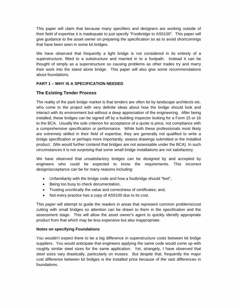
You wouldn’t expect there to be a big difference in superstructure costs between kit bridge suppliers. You would anticipate that engineers applying the same code would come up with roughly similar steel sizes for the same application. Yet, strangely, I have observed that steel sizes vary drastically, particularly on trusses. But despite that, frequently the major cost difference between kit bridges is the installed price because of the vast differences in foundations.

Hardwood Post set in concrete – less than 25 year design life
50mm trip hazard after about 8 years on the same bridge
It is possible to build a foundation that is very inexpensive but should they be accepted? The hardwood post above, even if it is In Ground Durability 1 would have a life expectancy of 25-50 years. This means a design life of 25 years. But that is only if the post is set in natural earth, fine crushed rock or no fines concrete. The design life is shorter when set in concrete. How much shorter will all depend on how much it rains. I have seen an Ironbark pole rot of at ground line in 14 years simply because it was set in concrete. In this particular project these low cost foundations were chosen over concrete abutments where the approach path, over highly reactive soil, was tied into foundations to prevent differential movement between the bridge and the footpath. There are major public liability issues through the trip hazards that can result.
No side walls allow soil to encroach on H3 treated timber
The timber in the trussed bridge illustrated is pine presumably treated to H3. After the soil has encroached on it (and really in any case where there is less than about 200mm clearance), it has become a H5 application. The Timberlife design life prediction software estimates the serviceability (50 % strength) of a 150x50 treated to H3 when used in an above ground application of somewhere between 75 to 90 years and replacement at about

100 years. When the same timber is in ground contact it only has a serviceability of 25 years. These examples show that a low initial cost for the foundations can be very expensive in the long run and it is therefore important not to accept them.
Unless there is a very good reason why not, and they do occur, a specification for a light bridge should stipulate that the abutments are to be built in concrete and incorporate an integral back and side wall. Further features of a well designed foundation should include a sloping surface towards the front to shed any moisture, have bearings set about 25-50 mm above the foundation on dry pack and allow for easy inspection for termites, rust etc.
A bridge abutment that incorporates OSA’s recommendations for a good foundation
Notes on Specifying Timber
In Queensland, in our own structures we expect a 20-25 year design life for our decking. The design life software mentioned earlier predicts an 85 year life for our hardwood joists and bearers detailed the way we recommend. This assumes doing nothing to the timber apart from an initial oiling. I am aware that these life spans are different from many designers experience or expectation. From our years of experience and formal research we have a good understanding of what parts of standards we have to supply to are simply wrong or misleading. A fairly standard timber specification says something like F17 hardwood, treated to H5, durability class 2. It sounds good and three Australian Standards are called up. In reality it says nothing meaningful! Consider timber specified as F14 of F17 to AS2082. This is simply a specification of strength on the day of milling, nothing more. The properties you need are durability, stability, shrinkage and appearance none of which are covered in timber that is simply sold by an F rating. If purchasing on price you are not likely to get the species with the properties or physical appearance you want as they are more expensive.

It is also little understood that it is impossible to “preserve” sawn timber. It is only possible to treat sapwood, not heartwood by commercial waterborne preservatives such as CCA, Tanalith E or ACQ. Consider the following. I can take a piece of blackbutt, a low Durability 2 In Ground timber, without any sap and paint on CCA with a paintbrush. Dsepite that being a total waste of time I am then allowed to stamp that member as a H5 piece of timber. Further I can then dress that same piece of timber and remove all traces of the green colouring and I am still entitled to call that a H5 piece of timber! It clearly isn’t preserved yet AS1604.1 (Specification for Preservative Treatment Part 1 – Sawn and round timber) is satisfied and would claim that it the equal to a piece of grey ironbark containing a little sapwood. The figure above shows what a piece of F11 to F17 spotted gum theoretically looks like. There is 20% of its cross section missing. Sapwood on Joists and bearers is seldom more than 15%. This means that if the timber is not treated at all it invariably will still meet the structural requirements! How long the member lasts will have nothing to do with its H level of treatment but its natural durability!
Theoretical Cross Sections to AS2082 Actual sapwood (highlighted red) in a pack of 200x100

Garo Garo (so called Pacific tallowwood) an In Ground Durability 3, timber, Above ground Durability 2 timber after 4 years in North Queensland
The natural durability ratings (AS5604) are also a problem. This can be because of specifiers who have not kept up with the change to the standard – durability ratings are now classed as In Ground and Above Ground durability. If you specify the old way, say Durability Class 2, the supplier can say, this is an above ground application therefore it is an Above Ground 2 and supply an old In Ground 3 timber (as illustrated above). These In Ground 3 timbers never were acceptable and remain unacceptable despite ticking the correct boxes. Further problems arise through the wide spread of durability within a group. Above Ground 1 will pick up Blackbutt yet in Queensland it is not considered suitable for a railway sleeper, crossarm or for timber bridges. These are applications where timber species performance has been monitored. How can it now be suitable for a light bridge? The life expectancy figures in the standard also bear little relation to reality when it comes to decking and the fine print in the Standard about their accuracy is not given due attention. The old designation of Royal Species for those few species that perform well above the rest has been lost. Appendix 2 contains a copy of Timber Queensland’s warning in relation to AS5604 (presently being updated but not at hand at time of writing).
So timber specifications have to go far beyond Australian Standards, and we find many designers have a great reluctance to do this. The designer either has to be an expert in timber design or take the safer path of proprietary products such as Deckwood. But taking the trouble to go beyond the standards will be rewarding, both financially and in supplying a structure that ages gracefully. But how do you do this? It is not easy which is the reason we introduced our proprietary Deckwood and Joistwood.

Nail plates need to be closely screwed to prevent them working out
When timber joints are weather exposed, the connections also need to be different to say a roof truss where the joints are not stressed by wetting and drying of the timber. The load carrying ability drops to a half when the plate has worked out just 2-3mm. When nail plates are used they need supplementary fastenings such as closely screwing with stainless screws. This almost negates the purpose of using a nail plate in the first place. Surprisingly painted housed joints have been found to deteriorate more rapidly than unpainted joints.
A Note on Inundation
When inundation is being considered we have found that, invariably, the reference point is the Q100 event, which invariably represents a large general flood. In these conditions the stream flow may not be significant with many areas simply becoming backwaters. Flooding may be entirely different in lesser events when there is only localised flooding to consider. When determining the design speed it is necessary to look at the characteristics of both generalised and localised flooding.
A Bridge too Far.
Theoretically, kit bridges should be the best bridges on the market. The manufacturer has had the opportunity to refine and simplify the design through constant reuse and review. Sometimes theory does not translate into actual practice. The following account of a bridge that was dangerous from the time of installation vividly illustrates what can go wrong. It shows why there is need to have both a very detailed tender and assessment requirements.
In 2010 I was stopped in the street by my local state MP who asked what I knew about a certain recently installed bridge. He explained that he had received numerous complaints from his constituents complaining that the bridge deck was very slippery and that they felt

unsafe as they crossed the bridge because it shook so badly! I knew the bridge well, a 32 metre imported aluminium truss, and I also had come to same conclusion as to its safety. The bridge connects the residents of a retirement home with their church so these were serious issues.
What do you do in such a situation? I knew the people who used this bridge, and believed that bridges with this performance and safety should not be used by the public. I had quoted for the supply of this bridge based on supplying a structure designed to AS5100 as the customer required along with their specific requirements. For the first time in my life I stood my ground on a lost tender. I re-examined the tender conditions, obtained information on the bridge under FOI, discussed aspects of the bridge code with our Consulting Engineer and then complained officially to the asset owner.
This involved a 11 page letter showing what we believed to be non conformance to AS5100 followed by a one hour PowerPoint to the Councillors. Two days later the CEO rang me and said “We all thought you were just upset about not winning the tender but you spoke with such sincerity that we all saw that you have a passion for your product. Let me tell you that I have personally inspected the bridge and everything you said is correct. We will not be letting the matter rest”. Major repairs started just prior to Christmas 2010. They have proved inadequate.
Where did this Bridge go Wrong?
The tender was not at fault. It specifically required the bridge to be built to AS5100, nominated a flood speed for inundation, had a soil test (but without recommendations) and nominated a deck loading (20kN) and handrail height of 1300mm. A cross section of the waterway was also supplied and construction material nominated. This is more than we generally see and should have been adequate. Where this bridge went wrong was that the customer did not have processes in place to check documents before final approval to construct and then for checking the installed product. The first check would have identified documentation that made no reference to AS5100, used the wrong code for loadings, no member sizes, no bolt sizes, and plans in a foreign language without translation. Further it was certified as a steel bridge despite being constructed of aluminium! This underscores the importance of plans being in English!
PART 2 – THE TENDER ITSELF
Before you Start
A client wanting a footbridge MUST be prepared to do basic preliminary work. A cross section of the waterway must be prepared and made available in CAD format. It should show the Q100 flood level and the normal stream level. A soil test must be taken and a recommendation given and a stream flow nominated. This is usually not done. The
Major repairs being undertaken on a new footbridge Dec 2010

prevailing view with the soil test seems to be – let the contractor price this in to the project and we can get this tender out with minimal cost and outlay. But this is false economy. The tenderers are not going to undertake the investigation prior to quoting. Instead there will be assumptions made and these will assume worst case scenario and will result in estimating the cost of foundations that are generally more expensive than if the actual conditions are known. The asset owner, who has tried to save money, eventually, pays for the soil test plus the contractor’s margin plus what is “pocketed” through the site being easier than assumed. Alternatively a quote may nominate its assumptions and a claim made if foundations requirements are outside of those nominated. In Appendix I give the recommendation from our Light Bridge Manual for a site investigation and geotechnical investigation.
Not every bridge can be built above the Q100. When the bridge is likely to be inundated a design speed must be nominated. We recently quoted a major bridge where the velocity was not nominated in the documentation. On phoning the client I was advised that I had to undertake our own flood study prior to quoting so “the Council did not have to bear any of the risk” as “Council does not have the resources or data available to provide tenderers with advice re: velocities”. Fortunately a very helpful engineer heard through a third party that we were floundering and advised that there already was a flood study in their office with all the information I needed. The bridge was 34 metres clear span and the flow was 2.9 m/s and had to be quoted as a truss! We could not provide an economic truss to meet that specification. Earlier advice was that the bridge was situated in a backwater and there was no flow.
The client has a very large investment in infrastructure both in dollars and in reputation, if a bridge fails, the public will see it as failure by council, not failure by the contractor and the first step in protecting the council’s reputation is through supplying full and accurate information at the design stage. It is also the first step in minimising the cost.
Suggested Specifications are as follows:

FOOTBRIDGE SPECIFICATION & ASSESSMENT CRITERIA Notes
This specification is NOT applicable for a • bridge over a major road or railway • bridge assessed as a Walking Track Structure (AS 2156.2) • dedicated bikeway or shared use path (see separate Spec.) • bridge with a deck area >85 m2 • bridge with substantial tractor/mower loads
The bridge shall be designed in most respects to AS 5100 Bridge Design but with special attention drawn to the following conditions/variations
Condition Requirements Conform – circle which applies
BASIC PERFORMANCE REQUIREMENTS Span at hold down bolts is Yes No ? Clear width between handrails is Yes No ?Distributed load 5 kPa Yes No ?Point Load 4.5 kN Yes No ?Load Factor (not over a road/railway) 1.5 Yes No ?First Natural Frequency 3.5 hertz Yes No ? Note: A bridge of 3 kPa will not be accepted
EXTRA REQUIREMENTS FOR SERVICE VEHICLE A service vehicle with a GVM ??? will also use the bridge at low speed
Yes or No Yes No ?
Minimum width requirement is 2.7m Yes No ?Distributed load Yes No ?Point load Yes No ?
INUNDATION This bridge will be submerged in a Q100 event Yes or No Yes No ?If Yes, what speed in m/s if not nominal ??m/s Yes No ?The bridge will be submerged in what more frequent event
Q? Yes No ?
Design velocity if not nominal ? m/s Yes No ? Flow height above deck Yes No ?Flow depth to average stream bed Yes No ?Shear restraints required when flooding is not nominal Yes No ?
HANDRAIL INFORMATION Minimum height 1.1m Yes No ?To comply with BCA Yes No ? To comply with AS 5100 Yes No ? Lateral Load 0.75 kN/m Yes No ?Vertical Load 0.75 kN/m Yes No ?Frangible Rails required Yes or No Yes No ? In other respects does the handrail comply with BCA Yes or No Yes No ?Stiffness required is span (between posts) of 1/800 Yes No ?Tamper resistant fittings to stainless wires? Yes or No Yes No ?Note 1: with BCA compliant rails, any wires are 60mm apart at 2.0m post centres Note 3: Frangible rails must still meet 0.75 kN/m laterally and vertically

MINIMUM STEEL THICKNESS 4 mm for tubular sections Yes No ?
USE OF TIMBER Minimum grade for joists F17 Yes No ?Acceptable species include Spotted Gum, Ironbark, Gympie Messmate. Blackbutt is not acceptable
Yes No ?
Minimum grade for decking F22 face Yes No ?Acceptable species as per joists Yes No ?Dampcourse is required on joists with CN emulsion Yes No ?Decking to be Oiled with CN Oil Yes No ? Yes No ?
NOTES ABOUT TRUSSES Note 1: Trusses shall be designed using the “U Frame’ method Note 2: Balusters on truss handrail are to stand 100 mm free of the trussNote 3: “Duragal” is not accepted – hot dipped gal or high corrosion resistant paint only Note 4: Timber trusses are not to be nail plated unless closely screwed as well
FOUNDATIONS Terminate with concrete abutments Yes Yes No ? Integrated side and back wall required Yes Yes No ? Is the approach path integrated into the abutment Yes Yes No ? 50 year life on bridge bearings Yes Yes No ?
DOCUMENTATION At tender stage – typical drawings, images and/or brochures will suffice On granting of order – Step 1 Assessment - working drawing prepared by a registered engineer marked “not for construction” are to be submitted for assessment. Plans are to be in English On Granting of order – Step 2 – Approval – on assessment of drawings, and making any changed that are deemed necessary, a new set of drawings are to be submitted On Completion of project – The successful tenderer is/is not (delete whichever does not apply) required to provide a certificate of construction

CYCLEWAY/SHARED PATH SPECIFICATION & ASSESSMENT CRITERIA
Notes This specification is NOT applicable for a • cycleway over a major road or railway • bridge with a deck area >85 m2 • bridge with substantial tractor/mower loads
The bridge shall be designed in most respects to AS 5100 Bridge Design but with special attention drawn to the following conditions/variations
Condition Requirements Conform – circle which applies
BASIC PERFORMANCE REQUIREMENTS Span at hold down bolts is Yes No ? Clear width between handrails is (delete as needed) Yes No ?a. Commuting, Tidal flow, low use Minimum width 2.0m Yes No ?b. Commuting and local access regular use - Minimum 2.5m Yes No ?c. Commuting frequent and fast (30 kph) Minimum width 3.0m Yes No ?d. Recreation regular use Minimum width 3.0m Yes No ?d & c combined (30 kph) Minimum width 3.5m Yes No ?Distributed load 5 kPa Yes No ?Point Load 4.5 kN Yes No ?Load Factor (not over a road/railway) 1.5 Yes No ?First Natural Frequency 3.5 hertz Yes No ? Note: A bridge of 3 kPa will not be accepted
EXTRA REQUIREMENTS FOR SERVICE VEHICLE A service vehicle with a GVM ??? will also use the bridge at low speed
Yes or No Yes No ?
Minimum width requirement is 2.7m Yes No ?Distributed load Yes No ?Point load Yes No ?
INUNDATION This bridge will be submerged in a Q100 event Yes or No Yes No ?If Yes, what speed in m/s if not nominal ??m/s Yes No ?The bridge will be submerged in what more frequent event
Q? Yes No ?
Design velocity if not nominal ? m/s Yes No ? Flow height above deck Yes No ?Flow depth to average stream bed Yes No ?Shear restraints required when flooding is not nominal Yes No ?
HANDRAIL INFORMATION Minimum height 1.3m Yes No ? To comply with BCA Yes No ? To comply with AS 5100 Yes No ? Second offset rail 150mm from main handrail required Yes Yes No ? Note: Barrier is required when the fall height is >250mm Lateral Load 0.75 kN/m Yes No ?Vertical Load 0.75 kN/m Yes No ?

Frangible Rails required Yes or No Yes No ? In other respects does the handrail comply with BCA Yes or No Yes No ?Stiffness required is span (between posts) of 1/800 Yes No ?Tamper resistant fittings to stainless wires? Yes or No Yes No ? Note 1: with BCA compliant rails, any wires are 60mm apart at 2.0m post centres Note 3: Frangible rails must still meet 0.75 kN/m laterally and vertically
MINIMUM STEEL THICKNESS 4 mm for tubular sections Yes No ?
USE OF TIMBER Minimum grade for joists F17 Yes No ?Acceptable species include Spotted Gum, Ironbark, Gympie Messmate. Blackbutt is not acceptable
Yes No ?
Minimum grade for decking F22 face Yes No ?Acceptable species as per joists Yes No ?Dampcourse is required on joists with CN emulsion Yes No ?Decking to be Oiled with CN Oil Yes No ? Yes No ?
NOTES ABOUT TRUSSES Note 1: Trusses shall be designed using the “U Frame’ methodNote 2: Balusters on truss handrail are to stand 100 mm free of the truss Note 3: “Duragal” is not accepted – hot dipped gal or high corrosion resistant paint only Note 4: Timber trusses are not to be nail plated unless closely screwed as well
FOUNDATIONS Terminate with concrete abutments Yes Yes No ? Integrated side and back wall required Yes Yes No ? Is the approach path integrated into the abutment Yes Yes No ? 50 year life on bridge bearings Yes Yes No ?
DOCUMENTATION At tender stage – typical drawings, images and/or brochures will suffice On granting of order – Step 1 Assessment - working drawing prepared by a registered engineer marked “not for construction” are to be submitted for assessment. Plans are to be in English On Granting of order – Step 2 – Approval – on assessment of drawings, and making any changed that are deemed necessary, a new set of drawings are to be submitted On Completion of project – The successful tenderer is/is not (delete whichever does not apply) required to provide a certificate of construction

Appendix 1 Site Survey and Geotechnical Investigation
Site Survey
A site survey is necessary as a design aid and to properly locate the structure within the landscape. This is necessary from an aesthetic and practical point of view as, generally, OSA does not build on site but prefabricates the superstructure. They do not have the luxury of building to fit the actual site - only the representation of the site - so the site plan must be as complete as possible so that the structure fits both the site and its landscape setting.
The first source of information may be an ortho-photo that often includes contours. A detailed contour survey extending 50m up and 50m downstream is usually the best way of presenting the information together with a survey of the possible connections to the pathways. This should also include top of bank, existing water levels, tidal range, observed tide, relationship to AHD or tidal datum. Debris marks, flood levels, evidence of soil scour or siltation are all important.
Obstacles should be located on this plan including services (underground and overhead), pits and valves, signs, property boundaries, trees (including type, girth and root buttressing), roads, paths, fences barriers etc. Sufficient recovery marks including temporary benchmarks should be installed at this stage to enable future set-out. This work is best done by engineering surveyors with the output direct to CivilCAD or Land Development Desktop. OSA and their Consultant require any plans sent electronically in AutoCAD 2000 or DXF format.
The hydraulic consultant may also need information on upstream properties that could be affected by any damming effect of construction. Information on heavy vehicle access for construction, storage areas and site. Photos are also required.
Geotechnical Investigation
In comparison to typical civil engineering and building work, OSA's footbridge foundations are lightly loaded. Working bearing pressure on standard footings has been kept to 50kPa, acknowledging that the locations are often unsuitable for housing where 100kPa is the 'norm'. Working loads on piles are typically less than 100kN - an order of magnitude less than 'conventional' piling (1000kN). This means that light plantation pine piles are frequently used, making for economies in handling and driving. Piles may not have to be driven to rock by using skin friction to carry most of the load.
While the ground loadings for typical OSA's bridges are quite small, they still need to have adequate foundations. All bridges require a geotechnical investigation to determine the nature of the founding material so that economical foundations can be designed to adequately withstand the anticipated loadings.
Usually where we bridge creeks, the ground is poor, unconsolidated, erosion prone, waterlogged and susceptible to flooding during construction. In that situation small
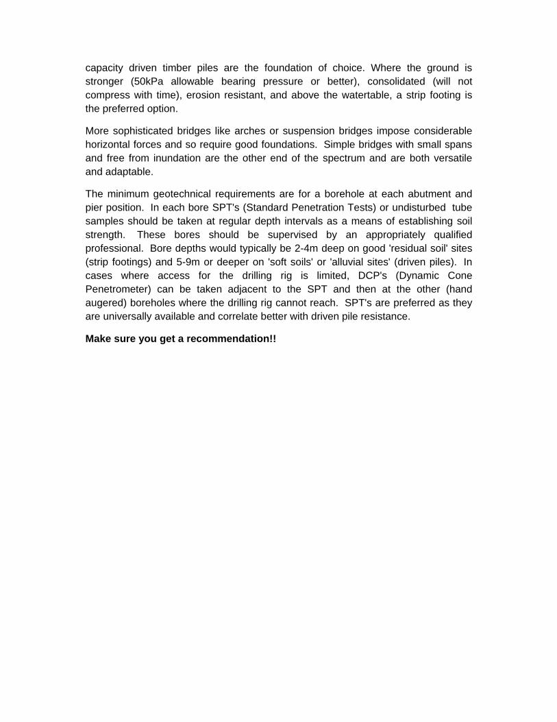
capacity driven timber piles are the foundation of choice. Where the ground is stronger (50kPa allowable bearing pressure or better), consolidated (will not compress with time), erosion resistant, and above the watertable, a strip footing is the preferred option.
More sophisticated bridges like arches or suspension bridges impose considerable horizontal forces and so require good foundations. Simple bridges with small spans and free from inundation are the other end of the spectrum and are both versatile and adaptable.
The minimum geotechnical requirements are for a borehole at each abutment and pier position. In each bore SPT's (Standard Penetration Tests) or undisturbed tube samples should be taken at regular depth intervals as a means of establishing soil strength. These bores should be supervised by an appropriately qualified professional. Bore depths would typically be 2-4m deep on good 'residual soil' sites (strip footings) and 5-9m or deeper on 'soft soils' or 'alluvial sites' (driven piles). In cases where access for the drilling rig is limited, DCP's (Dynamic Cone Penetrometer) can be taken adjacent to the SPT and then at the other (hand augered) boreholes where the drilling rig cannot reach. SPT's are preferred as they are universally available and correlate better with driven pile resistance.
Make sure you get a recommendation!!

Appendix 2 Timber Durability Rating Warning
(In the process of being updated)
PH: 07 5462 4255, FAX: 07 5462 4077, E-mail: [email protected]
EXTERNAL TIMBER DESIGN NOTE
No. 7 July 2006 – Durability Ratings and AS 5604 – Get it right!!
Timber Queensland (TQ) has confirmed Outdoor Structures concerns that AS5604 is still being misinterpreted. The following is a TQ update to their Technical Bulletin of June 2004.
“Timber Queensland still have concerns relating to the interpretation and application of above ground durability ratings now given for species listed in AS 5604.
In some quarters, the new above ground durability ratings given in this standard are being used to justify permanent, long term, above ground weather exposed applications (H3) for species where previously these species (based upon in-ground ratings) were not considered appropriate for long term application.
AS 5604 has a table that links the in-ground and above ground durability rating of species to a probable life expectancy as shown below.
Table 1 - NATURAL DURABILITY - PROBABLE LIFE EXPECTANCY*
Class Probable in-ground life expectancy (years)
Probable above-ground life expectancy (years)
1 Greater than 25 Greater than 40
2 15 to 25 15 to 40
3 5 to 15 7 to 15
4 0 to 5 0 to 7

• The ratings in this Table are based on expert opinions and the performance of the following test
specimens: -In-ground: 50 x 50 mm test specimens at five sites around Australia. -Above-ground: 35 x 35 mm test specimens at eleven sites around Australia
• As further reliable evidence becomes available, these ratings may require amending. The heartwood of an individual piece of timber may vary from the species' nominated classification. Above-ground conditions equate to outside above-ground subject to periodic moderate wetting when ventilation and drainage are adequate.
As can be seen from this table, the in-ground life expectancies for each class are the same as they have always been and, the historical expectation was that species with an in-ground rating of Class 1 or 2 would have above ground life expectancies of around 40 years plus which when coupled with appropriate maintenance etc, satisfies the implicit performance expectations of our current building regulations. Within AS 5604, as can be seen from the following table, many species that are rated Class 2 or better in-ground are rated Class 1 above ground and species rated Class 3 in-ground are rated Class 2 above ground, whilst other species ratings do not change.
Species Heartwood - In Ground
Durability Class Heartwood - Above Ground
Durability Class
Ash, silvertop 3 2
Blackbutt 2 1
Gum, blue, Sydney 3 2
Gum rose 3 2
Gum, spotted 2 1
Ironbark 1 1
Jarrah 2 2
Kapur 3 2
Kwila 3 1
Stringybark, brown 3 2 It is obvious from the above table that is extracted from AS 5604 and the Table above it, that just because species are now rated Class 2 above ground, does not mean that they will now perform any better than they have historically e.g. rose gum.”
It should be noted that for Qld, under the BCA, that Technical Pamphlet No 1 is still “the law”. This document has recently been extensively revised and updated to reflect current standards and the implicit BCA durability performance life expectancies and has been re-published as ‘Construction Timbers in Queensland’(CTIQ). This new document can be purchased from Timber Queensland by faxing back the attached order form.
It is expected that CTIQ will be called up by BCA 2007 to replace Technical Pamphlet 1.
As important specifiers and users of timber, Outdoor Structures encourages you to use our current recommendations which reflect the above, together with TQ’s recently updated Technical Data Sheets. You should also be updating your libraries with CTIQ which is expected to become the ‘law’ in the very near future.
To join TQ as a Professional Member and be able to access all the latest timber advice and recommendations, including the monthly Technical Update see www.timberqueensland.com.au
Ted Stubbersfield.