wp5 - computational mechanics b3 barrier - varioguard...
TRANSCRIPT

ROBUST PROJECT Department of Aerospace engineering* - Politecnico di Milano WP5 - Computational Mechanics B3 barrier - Varioguard MAIN REPORT Volume 1 of 1
(*)via La Masa, 34 Milan-ITALY tel: +39 02 23998316 - fax: +39 02 23998334 Jul 2005 Doc. No.: ROBUST-05-018 - Rev. 0

ROBUST project Page i
Department of Aerospace engineering Politecnico di Milano Doc. No.: ROBUST-05-018 - Rev. 0 WP5 - Computational Mechanics B3 barrier - Varioguard
MAIN REPORT
MAIN REPORT
Report title: WP5 - Computational Mechanics B3 barrier - Varioguard Doc. No.: ROBUST-05-018 - Rev. 0 Reporter(s):
Mario Mongiardini Abstract: The Robust Project aims to improve scientific and technical knowledge on the main issues still open in the new European standards on road restraint system EN 1317. The knowledge acquired will form the basis of updated standards for EN1317 and lead to more advanced road restraint systems and improve road-users safety. This report is part of the deliverables from Work Package 5 (WP5) - Computational Mechanics. KEYWORDS: Road restraint system, crash testing, Finite Element simulation
Rev. Date Prepared by Checked by Approved by Others
0 25/07/2005 Mario Mongiardini

ROBUST project Page ii
Department of Aerospace engineering Politecnico di Milano Doc. No.: ROBUST-05-018 - Rev. 0 WP5 - Computational Mechanics B3 barrier - Varioguard
MAIN REPORT
CONTENTS
ROBUST PROJECT........................................................i
1 INTRODUCTION ..........................................................1
2 SUMMARY AND CONCLUSIONS...............................2 Summary ...........................................................................................................................................2 2.1 Conclusions..........................................................................................................................3
3 SIMULATIONS RESULTS: CASE 1 ............................4 3.1 General ................................................................................................................................4 3.2 Additional data .....................................................................................................................4 3.3 Input data .............................................................................................................................4
3.3.1 Test items ............................................................................................................. 4 3.3.2 Test procedure...................................................................................................... 6 3.3.3 Barrier model ........................................................................................................ 6 3.3.4 Vehicle model ....................................................................................................... 7 3.3.5 Analysis data ........................................................................................................ 8
3.4 Analysis results ....................................................................................................................8 3.4.1 Barrier ................................................................................................................... 8 3.4.2 Vehicle .................................................................................................................. 9 3.4.3 General description of vehicle trajectory .............................................................. 9 3.4.4 Assessment of the impact severity ....................................................................... 9 3.4.5 Impact sequences and vehicle damage ............................................................. 11
4 SIMULATIONS RESULTS: CASE 2 ..........................17 4.1 General ..............................................................................................................................17 4.2 Additional data ...................................................................................................................17 4.3 Input data ...........................................................................................................................17
4.3.1 Test items ........................................................................................................... 17 4.3.2 Test procedure.................................................................................................... 18 4.3.3 Barrier model ...................................................................................................... 18 4.3.4 Vehicle model ..................................................................................................... 18 4.3.5 Analysis data ...................................................................................................... 18
4.4 Analysis results ..................................................................................................................19 4.4.1 Barrier ................................................................................................................. 19 4.4.2 Vehicle ................................................................................................................ 19 4.4.3 General description of vehicle trajectory ............................................................ 19

ROBUST project Page iii
Department of Aerospace engineering Politecnico di Milano Doc. No.: ROBUST-05-018 - Rev. 0 WP5 - Computational Mechanics B3 barrier - Varioguard
MAIN REPORT
4.4.4 Assessment of the impact severity ..................................................................... 20 4.4.5 Impact sequences and vehicle damage ............................................................. 21
5 SIMULATIONS RESULTS: CASE 3 ..........................27 5.1 General ..............................................................................................................................27 5.2 Additional data ...................................................................................................................27 5.3 Input data ...........................................................................................................................27
5.3.1 Test items ........................................................................................................... 27 5.3.2 Test procedure.................................................................................................... 27 5.3.3 Barrier model ...................................................................................................... 28 5.3.4 Vehicle model ..................................................................................................... 28 5.3.5 Analysis data ...................................................................................................... 29
5.4 Analysis results ..................................................................................................................29 5.4.1 Barrier ................................................................................................................. 29 5.4.2 Vehicle ................................................................................................................ 29 5.4.3 General description of vehicle trajectory ............................................................ 30 5.4.4 Assessment of the impact severity ..................................................................... 30 5.4.5 Impact sequences and vehicle damage ............................................................. 31
REFERENCES.................................................................37
ROBUST project Page 1/38
Department of Aerospace engineering Politecnico di Milano Doc. No.: ROBUST-05-018 - Rev. 0 WP5 - Computational Mechanics B3 barrier B3 barrier - Varioguard
MAIN REPORT
1 INTRODUCTION The Robust Project aims to improve scientific and technical knowledge on the main issues still open in the new European standards on road restraint system EN 1317. The knowledge acquired will form the basis of updated standards for EN1317 and lead to more advanced road restraint systems and improve road-users safety. This report is part of the deliverables from Work Package 5 - Computational Mechanics. The objective of WP5 is:
• Evaluation and enhancement of the use of computational mechanics to complement experimental activity
• Criteria and procedures for the validation of computational mechanics results through comparison with test results
• Reconstruction of real life accidents • Identification of the activity needed for further enhancement of the use of
computational mechanics. This report documents the simulation performed on the Varioguard barrier.

ROBUST project Page 2/38
Department of Aerospace engineering Politecnico di Milano Doc. No.: ROBUST-05-018 - Rev. 0 WP5 - Computational Mechanics B3 barrier B3 barrier - Varioguard
MAIN REPORT
2 SUMMARY AND CONCLUSIONS
Summary The simulations were run using the Non-Linear Finite Element code LS-Dyna. The following simulations were performed for the Varioguard barrier (see Table 3.1):
Barrier Vehicle Test ChapterMain characteristics Name id. Main Characteristics Name id. Case 1: • Barrier ends jointed to the ground • Car-barrier friction imposed.
Varioguard.dyn Geo-Metro (Ver.3): • Small car (900 kg) • Road-tyre friction=0.3 • Improved FE model (Steering system & Suspensions)
GM_R3.dyn TB11 3
Case 2: • Barrier ends jointed to the ground • No car-barrier friction.
Varioguard.dyn • Road-tyre friction=0.6 • Other features same as case 1.
Same as case 1 TB11 4
Case 3: • Barrier ends jointed to the ground • No vehicle-barrier friction.
Varioguard.dyn Heavy Good Vehicle: • Total mass 10000 kg • Road-tyre friction=0.6 • Fully working Steering system and Suspensions
HGV_10.dyn TB42 5
Case 4: • Barrier ends jointed to the ground • Road-barrier friction=0.35.
Varioguard.dyn Bus Vehicle: • Total mass 13000 kg • Road-tyre friction=0.6 • Partially working Suspensions • No Steering system
Bus_1.dyn TB51 6

ROBUST project Page 3/38
Department of Aerospace engineering Politecnico di Milano Doc. No.: ROBUST-05-018 - Rev. 0 WP5 - Computational Mechanics B3 barrier B3 barrier - Varioguard
MAIN REPORT
The main results are summarised in Table 2.1 below.
Case ASI [-]
THIV [km/h]
PHD [g]
Workingwidth [mm]
Exit speed[km/h]
Exit angle[deg]
Trajectory Detailed description
1 1.25 25.3 9.8 1422 78 1.5 Good Chapter 3 2 1.13 19.4 10.6 1564 90 0 Good Chapter 4 3 N/A N/A N/A 1850 66 4.5 Good Chapter 5
Table 2.1 Results form simulation of Varioguard barrier.
2.1 Conclusions NA

ROBUST project Page 4/38
Department of Aerospace engineering Politecnico di Milano Doc. No.: ROBUST-05-018 - Rev. 0 WP5 - Computational Mechanics B3 barrier B3 barrier - Varioguard
MAIN REPORT
3 SIMULATIONS RESULTS: CASE 1
3.1 General This chapter gives a brief description of the results obtained from the simulation of a TB11 test (small car of 900 kg) hitting the Varioguard barrier, with an initial velocity of 102.5 km/h and an angle of 20 degrees. The Varioguard barrier is a rigid, yet deformable, energy absorbing system that offers high containment protection to workzones or bridges. The barrier is made of galvanized steel with a unit length of 4,000 mm. The simulation reported in this chapter is characterized by the following:
• The barrier modules are not fixed (they simply lie on the road surface). • The endings of the barrier are jointed to the ground. • All parts of the barrier are modelled with a non-linear material (*MAT_PIECEWISE_LINEAR_PLASTICITY). • Friction between barrier and vehicle. • Friction between roadway and tires is 0.3 (road pavement modelled using a rigidwall).
3.2 Additional data The Severity Indexes evaluated in this chapter have been obtained from the following data and files:
• Rawdata files: Rawdata_C1.zip • Excel worksheet file: Accelerations&YawRate_C1.xls • TRAP files: Trap-files_C1.zip
The following animations of the simulation are available:
• front view: Front_view_C1.avi • rear view: Rear_view_C1.avi • side view. Side_view_C1.avi • top view: Top_view_C1.avi • perspective: Perspective_view_C1.avi
3.3 Input data
3.3.1 Test items Barrier Varioguard steel barrier Vehicle GeoMetro (version GM_R3)Drawings See Table 3.1

ROBUST project Page 5/38
Department of Aerospace engineering Politecnico di Milano Doc. No.: ROBUST-05-018 - Rev. 0 WP5 - Computational Mechanics B3 barrier B3 barrier - Varioguard
MAIN REPORT
Vario
A-B
Vario
6 m 4000 mm 4000 mm
0000 m
B
Agu
arri
B-B
gu
ard barrier
er terminal
arrier
ard section Table 3.1
508
mm
37
8 m
m
A

ROBUST project Page 6/38
Department of Aerospace engineering Politecnico di Milano Doc. No.: ROBUST-05-018 - Rev. 0 WP5 - Computational Mechanics B3 barrier B3 barrier - Varioguard
MAIN REPORT
3.3.2 Test procedure Test type: TB11 TB11 test Impact speed : 102.5 km/h Impact angle: 20 degrees Impact point: ≈ 20 meters from the beginning of the barrier Spinning wheels: Yes Inertial vehicle test mass: 928 kg
3.3.3 Barrier model Barrier type: Steel H2-type Number of posts: 49 (including 2x2 posts of the terminal modules) Spacing: ≈ 1333 m Total length: ≈ 68 m (see the plot of the barrier model in Table 3.2) Element type: Shell elements used for all sections Connection/Joints: Connections modelled merging coincident nodes at bolt
spots or defining nodal rigid body between jointed parts. Foundation: Barrier modules simply lay on the road surface End anchoring: Barrier terminals jointed to the ground Soil (type and formulation):
NA
Roadway: NA Plot of FE-model: See Table 3.2 Material data: See Table 3.3
Varioguard barrier FE model:
• The posts are 850 mm high (completely above the ground level)
• The barrier endings are constrained to the road pavement by a joint revolute
N° of nodes: 127102 N° of elements: 122598

ROBUST project Page 7/38
Department of Aerospace engineering Politecnico di Milano Doc. No.: ROBUST-05-018 - Rev. 0 WP5 - Computational Mechanics B3 barrier B3 barrier - Varioguard
MAIN REPORT
Table 3.2
Parts Density
[kg/m^3] Elastic module [Mpa]
Poisson’s ratio
Yield stress [Mpa]
Ultimate stress [Mpa]
Failure strain
ALL 7800 207000 0.3 235 450 NA
0
50
100
150
200
250
300
350
400
450
500
0 0.05 0.1 0.15 0.2 0.25
Strain
Stre
ss [M
Pa]
Table 3.3
3.3.4 Vehicle model GeoMetro (version GM_R3). This Finite Element vehicle model is characterized by a fully working steering system and front & rear suspensions. For documentation see Ref. 3.

ROBUST project Page 8/38
Department of Aerospace engineering Politecnico di Milano Doc. No.: ROBUST-05-018 - Rev. 0 WP5 - Computational Mechanics B3 barrier B3 barrier - Varioguard
MAIN REPORT
Z
Y
X
Figure 1
3.3.5 Analysis data Timestep: Max: 1.19 E-6
min: 1.22 E-6 Mass scaling option NO Code version / Precision: Ls–Dyna 960 /
Single static coefficient 0.3 Friction barrier/vehicle: dynamic coefficient 0.2 static coefficient 0.3 Friction wheel/ground: dynamic coefficient NA
Friction other: NA Respect to the CoG (see Figure 1):
Longitudinal 111 mm Lateral 32 mm
Accelerometer location (mounting block):
Vertical 138 mm Sampling rate: 100 kHz
3.4 Analysis results
3.4.1 Barrier Maximum global dynamic deflection: 1320 mm Working width: 1390 mm W5 Maximum global permanent deflection: 1290 mm Length of contact: ≈ 9 m Major parts fractured or detached: only one bracket detached

ROBUST project Page 9/38
Department of Aerospace engineering Politecnico di Milano Doc. No.: ROBUST-05-018 - Rev. 0 WP5 - Computational Mechanics B3 barrier B3 barrier - Varioguard
MAIN REPORT
Description of damage to test items: The profile detached from posts in the
zone of contact (posts knocked down)Ground anchorages meets design levels: NA Plot of test items: See below (Table 3.4-3.7)
3.4.2 Vehicle Exit speed: 78 km/h Exit angle: 1.5 degrees Rebound distance: NA Vehicle breaches barrier: No Vehicle passes over the barrier: No Vehicle within CEN .box.: Yes Vehicle rolls over after impact: No Damage to test vehicle: See below (Table 3.9)
3.4.3 General description of vehicle trajectory The vehicle hits the barrier with an initial angle of 20° and exits with an angle of about 1.5 degrees. The vehicle does not pass over the barrier and does not roll-over. Hence the trajectory can be considered good. The initial speed is 102.5 km/h, while the exit speed is 78 km/h. Vehicle damage TAD: NA Vehicle damage VDI: NA Vehicle cockpit def. index VCDI: NA Major parts of vehicle detached: No Plots of the vehicle: See below (Table 3.9)
3.4.4 Assessment of the impact severity Post-processing procedure: Data from nodout database (node 700002) pre-filtered with a SAE60 filter and subsequently post-processed in TRAP with a second SAE180 filter. Acceleration severity index (ASI): 1.25 Acceleration graphs: NA THIV: 25.3 km/h Time of flight: NA Post-impact head deceleration (PHD): 9.8 g’s Flail space: 300 mm in y-direction

ROBUST project Page 10/38
Department of Aerospace engineering Politecnico di Milano Doc. No.: ROBUST-05-018 - Rev. 0 WP5 - Computational Mechanics B3 barrier B3 barrier - Varioguard
MAIN REPORT

ROBUST project Page 11/38
Department of Aerospace engineering Politecnico di Milano Doc. No.: ROBUST-05-018 - Rev. 0 WP5 - Computational Mechanics B3 barrier B3 barrier - Varioguard
MAIN REPORT
3.4.5 Impact sequences and vehicle damage
Front view t=0 sec t=0.11 sec
t=0.22 sec t=0.33 sec
t=0.44 sec t=0.55 sec
Table 3.4
ROBUST project Page 12/38
Department of Aerospace engineering Politecnico di Milano Doc. No.: ROBUST-05-018 - Rev. 0 WP5 - Computational Mechanics B3 barrier B3 barrier - Varioguard
MAIN REPORT
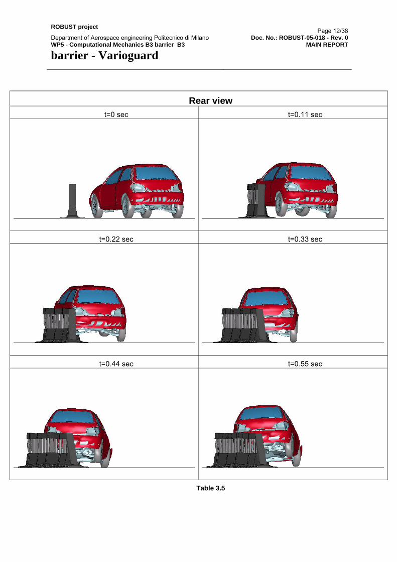
Rear view t=0 sec t=0.11 sec
t=0.22 sec t=0.33 sec
t=0.44 sec t=0.55 sec
Table 3.5

ROBUST project Page 13/38
Department of Aerospace engineering Politecnico di Milano Doc. No.: ROBUST-05-018 - Rev. 0 WP5 - Computational Mechanics B3 barrier B3 barrier - Varioguard
MAIN REPORT
Top view t=0 sec t=0.11 sec
t=0.22 sec t=0.33 sec
t=0.44 sec t=0.55 sec
Table 3.6

ROBUST project Page 14/38
Department of Aerospace engineering Politecnico di Milano Doc. No.: ROBUST-05-018 - Rev. 0 WP5 - Computational Mechanics B3 barrier B3 barrier - Varioguard
MAIN REPORT
Side view t=0 sec t=0.11 sec
t=0.22 sec t=0.33 sec
t=0.44 sec t=0.55 sec
Table 3.7
ROBUST project Page 15/38
Department of Aerospace engineering Politecnico di Milano Doc. No.: ROBUST-05-018 - Rev. 0 WP5 - Computational Mechanics B3 barrier B3 barrier - Varioguard
MAIN REPORT
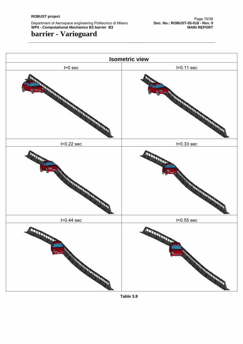
Isometric view t=0 sec t=0.11 sec
t=0.22 sec t=0.33 sec
t=0.44 sec t=0.55 sec
Table 3.8

ROBUST project Page 16/38
Department of Aerospace engineering Politecnico di Milano Doc. No.: ROBUST-05-018 - Rev. 0 WP5 - Computational Mechanics B3 barrier B3 barrier - Varioguard
MAIN REPORT
Vehicle damage Top Bottom
Right Left
Right Iso Left Iso
Table 3.9

ROBUST project Page 17/38
Department of Aerospace engineering Politecnico di Milano Doc. No.: ROBUST-05-018 - Rev. 0 WP5 - Computational Mechanics B3 barrier B3 barrier - Varioguard
MAIN REPORT
4 SIMULATIONS RESULTS: CASE 2
4.1 General This chapter gives a brief description of the results obtained from the simulation of a TB11 test (small car of 900 kg) hitting the Varioguard barrier, with an initial velocity of 102.5 km/h and an angle of 20 degrees. The Varioguard barrier is a rigid, yet deformable, energy absorbing system that offers high containment protection to workzones or bridges. The barrier is made of galvanized steel with a unit length of 4,000 mm. The simulation reported in this chapter is characterized by the following (differences with CASE 1 are in bold text):
• The barrier modules are not fixed (they simply lie on the road surface). • The endings of the barrier are jointed to the ground. • All parts of the barrier are modelled with a non-linear material (*MAT_PIECEWISE_LINEAR_PLASTICITY). • No friction between barrier and vehicle. • Friction between roadway and tires is 0.6 (road pavement modelled using a rigidwall).
4.2 Additional data The Severity Indexes evaluated in this chapter have been obtained from the following data and files:
• Rawdata files: Rawdata_C2.zip • Excel worksheet file: Accelerations&YawRate_C2.xls • TRAP files: Trap-files_C2.zip
The following animations of the simulation are available:
• front view: Front_view_C2.avi • rear view: Rear_view_C2.avi • side view: Side_view_C2.avi • top view: Top_view_C2.avi • perspective: Perspective_view_C2.avi
4.3 Input data
4.3.1 Test items Barrier Varioguard steel barrier Vehicle GeoMetro (version GM_R3)Drawings See Table 3.1

ROBUST project Page 18/38
Department of Aerospace engineering Politecnico di Milano Doc. No.: ROBUST-05-018 - Rev. 0 WP5 - Computational Mechanics B3 barrier B3 barrier - Varioguard
MAIN REPORT
4.3.2 Test procedure Test type: TB11 TB11 test Impact speed : 102.5 km/h Impact angle: 20 degrees Impact point: ≈ 20 meters from the beginning of the barrier Spinning wheels: Yes Inertial vehicle test mass: 928 kg
4.3.3 Barrier model Barrier type: Steel H2-type Number of posts: 49 (including 2x2 posts of the terminal modules) Spacing: ≈ 1333 m Total length: ≈ 68 m (see the plot of the barrier model in Table 3.2) Element type: Shell elements used for all sections Connection/Joints: Connections modelled merging coincident nodes at bolt
spots or defining nodal rigid body between jointed parts. Foundation: Barrier modules simply lay on the road surface End anchoring: Barrier terminals jointed to the ground Soil (type and formulation):
NA
Roadway: NA Plot of FE-model: See Table 3.2 Material data: See Table 3.3
4.3.4 Vehicle model GeoMetro (version GM_R3). See paragraph 3.3.4.
4.3.5 Analysis data Timestep: Max: 1.225E-6
min: 1.2 E-6 Mass scaling option NO Code version / Precision: Ls-Dyna 970 /
Single static coefficient 0 Friction barrier/vehicle: dynamic coefficient 0

ROBUST project Page 19/38
Department of Aerospace engineering Politecnico di Milano Doc. No.: ROBUST-05-018 - Rev. 0 WP5 - Computational Mechanics B3 barrier B3 barrier - Varioguard
MAIN REPORT
static coefficient 0.6 Friction wheel/ground: dynamic coefficient NA
Friction other: NA Respect to the CoG (see Figure 1):
Longitudinal 111 mm Lateral 32 mm
Accelerometer location (mounting block):
Vertical 138 mm Sampling rate: 100 kHz
4.4 Analysis results
4.4.1 Barrier Maximum global dynamic deflection: 1020 mm Working width: 1564 mm W5 Maximum global permanent deflection: 1000 mm Length of contact: > 15 m Major parts fractured or detached: No relevant parts detached or fractured Description of damage to test items: Relevant movement of the barrier
modules in the impact zone Ground anchorages meets design levels:
NA
Plot of test items: See below (Table 4.1-4.4)
4.4.2 Vehicle Exit speed: ≈ 90 km/h Exit angle: 0 degrees (parallel to the barrier) Rebound distance: NA Vehicle breaches barrier: No Vehicle passes over the barrier: No Vehicle within CEN .box.: Yes Vehicle rolls over after impact: No Damage to test vehicle: See below (Table 4.6)
4.4.3 General description of vehicle trajectory The vehicle hits the barrier with an initial angle of 20 degrees and exits with an angle of about 0 degrees (it slides along the barrier longitudinal direction!). The vehicle does not pass over the barrier and does not roll-over. Hence the trajectory can be considered good. The initial speed is 102.5 km/h, while the exit speed is close to 90 km/h.

ROBUST project Page 20/38
Department of Aerospace engineering Politecnico di Milano Doc. No.: ROBUST-05-018 - Rev. 0 WP5 - Computational Mechanics B3 barrier B3 barrier - Varioguard
MAIN REPORT
During the impact, the barrier modules directly involved in the crash have a relevant movement due to the fact that they simply lie on the road surface without any constraint. Vehicle damage TAD: NA Vehicle damage VDI: NA Vehicle cockpit def. index VCDI: NA Major parts of vehicle detached: No Plots of the vehicle: See below (Table 4.6)
4.4.4 Assessment of the impact severity Post-processing procedure: Data from nodout database (node 700002) pre-filtered with a SAE60 filter and subsequently post-processed in TRAP with a second SAE180 filter. Acceleration severity index (ASI): 1.13 Acceleration graphs: NA THIV: 19.4 km/h Time of flight: NA Post-impact head deceleration (PHD): 10.6 g Flail space: 300 mm in y-direction

ROBUST project Page 21/38
Department of Aerospace engineering Politecnico di Milano Doc. No.: ROBUST-05-018 - Rev. 0 WP5 - Computational Mechanics B3 barrier B3 barrier - Varioguard
MAIN REPORT
4.4.5 Impact sequences and vehicle damage
Front view t=0 sec t=0.12 sec
t=0.24 sec t=0.36 sec
t=0.48 sec t=0.60 sec
Table 4.1

ROBUST project Page 22/38
Department of Aerospace engineering Politecnico di Milano Doc. No.: ROBUST-05-018 - Rev. 0 WP5 - Computational Mechanics B3 barrier B3 barrier - Varioguard
MAIN REPORT
Rear view t=0 sec t=0.12 sec
t=0.24 sec t=0.36 sec
t=0.48 sec t=0.60 sec
Table 4.2

ROBUST project Page 23/38
Department of Aerospace engineering Politecnico di Milano Doc. No.: ROBUST-05-018 - Rev. 0 WP5 - Computational Mechanics B3 barrier B3 barrier - Varioguard
MAIN REPORT
Top view t=0 sec t=0.12 sec
t=0.24 sec t=0.36 sec
t=0.48 sec t=0.60 sec
Table 4.3

ROBUST project Page 24/38
Department of Aerospace engineering Politecnico di Milano Doc. No.: ROBUST-05-018 - Rev. 0 WP5 - Computational Mechanics B3 barrier B3 barrier - Varioguard
MAIN REPORT
Side view t=0 sec t=0.12 sec
t=0.24 sec t=0.36 sec
t=0.48 sec t=0.60 sec
Table 4.4

ROBUST project Page 25/38
Department of Aerospace engineering Politecnico di Milano Doc. No.: ROBUST-05-018 - Rev. 0 WP5 - Computational Mechanics B3 barrier B3 barrier - Varioguard
MAIN REPORT
Isometric view t=0 sec t=0.12 sec
t=0.24 sec t=0.36 sec
t=0.48 sec t=0.60 sec
Table 4.5

ROBUST project Page 26/38
Department of Aerospace engineering Politecnico di Milano Doc. No.: ROBUST-05-018 - Rev. 0 WP5 - Computational Mechanics B3 barrier B3 barrier - Varioguard
MAIN REPORT
Vehicle damage Top Bottom
Right Left
Right Iso Left Iso
Table 4.6

ROBUST project Page 27/38
Department of Aerospace engineering Politecnico di Milano Doc. No.: ROBUST-05-018 - Rev. 0 WP5 - Computational Mechanics B3 barrier B3 barrier - Varioguard
MAIN REPORT
5 SIMULATIONS RESULTS: CASE 3
5.1 General This chapter gives a brief description of the results obtained from the simulation of a TB42 test (HGV of 10000 kg) hitting the Varioguard barrier, with an initial velocity of 70 km/h and an angle of 15 degrees. The Varioguard barrier is a rigid, yet deformable, energy absorbing system that offers high containment protection to workzones or bridges. The barrier is made of galvanized steel with a unit length of 4,000 mm. The simulation reported in this chapter is characterized by the following:
• The barrier modules are not fixed (they simply lie on the road surface). • The endings of the barrier are jointed to the ground. • All parts of the barrier are modelled with a non-linear material (*MAT_PIECEWISE_LINEAR_PLASTICITY). • No Friction between barrier and vehicle. • Friction between roadway and tires is 0.6 (road pavement modelled using a rigidwall).
5.2 Additional data No Severity Indexes were evaluated for this simulation, as they are not required by the EN 1317 standards. The following animations of the simulation are available:
• front view: Front_view_C3.avi • rear view: Rear_view_C3.avi • side view: Side_view_C3.avi • top view: Top_view_C3.avi • perspective: Perspective_view_C3.avi
5.3 Input data
5.3.1 Test items Barrier Varioguard steel barrier Vehicle Heavy Good Vehicle (10 tons)Drawings See Table 3.1
5.3.2 Test procedure Test type: TB42

ROBUST project Page 28/38
Department of Aerospace engineering Politecnico di Milano Doc. No.: ROBUST-05-018 - Rev. 0 WP5 - Computational Mechanics B3 barrier B3 barrier - Varioguard
MAIN REPORT
TB42 test Impact speed : 70 km/h Impact angle: 15 degrees Impact point: ≈ 28 meters from the beginning of the barrier Spinning wheels: Yes Inertial vehicle test mass: 10000 kg
5.3.3 Barrier model Barrier type: Steel H2-type Number of posts: 49 (including 2x2 posts of the terminal modules) Spacing: ≈ 1333 m Total length: ≈ 68 m (see the plot of the barrier model in Table 3.2) Element type: Shell elements used for all sections Connection/Joints: Connections modelled merging coincident nodes at bolt
spots or defining nodal rigid body between jointed parts. Foundation: Barrier modules simply lay on the road surface End anchoring: Barrier terminals jointed to the ground Soil (type and formulation):
NA
Roadway: NA Plot of FE-model: See Table 3.2 Material data: See Table 3.3
5.3.4 Vehicle model Heavy Good Vehicle (10 tons). This vehicle model is a Heavy Good truck type with a total mass of 10 tons. The Finite Element model is characterized by a fully working steering system and front & rear suspensions. Both front and rear wheels can spin around their axis. Although possible, the version used did not allow failure of the linkage between front axle and the respective suspensions. For further documentation see Ref. 4.
Z
X
Y

ROBUST project Page 29/38
Department of Aerospace engineering Politecnico di Milano Doc. No.: ROBUST-05-018 - Rev. 0 WP5 - Computational Mechanics B3 barrier B3 barrier - Varioguard
MAIN REPORT
Figure 2
5.3.5 Analysis data Timestep: Max: 1.3E-6
min: 1.18 E-6 Mass scaling option NO Code version / Precision: Ls-Dyna 970 /
Single static coefficient 0 Friction barrier/vehicle: dynamic coefficient 0 static coefficient 0.6 Friction wheel/ground: dynamic coefficient NA
Friction other: NA Respect to the CoG (see Figure 1):
Longitudinal N/A Lateral N/A
Accelerometer location (mounting block):
Vertical N/A Sampling rate: N/A
5.4 Analysis results
5.4.1 Barrier Maximum global dynamic deflection: 1592 mm Working width: 1850 mm W6 Maximum global permanent deflection: 1585 mm Length of contact: ≈ 11.5 m Major parts fractured or detached: No relevant parts detached or fractured Description of damage to test items: Relevant movement of the barrier
modules in the impact zone Ground anchorages meets design levels: NA Plot of test items: See below (Table 5.1-5.4)
5.4.2 Vehicle Exit speed: 66 km/h Exit angle: 4.5 degrees Rebound distance: NA Vehicle breaches barrier: No Vehicle passes over the barrier: No
ROBUST project Page 30/38
Department of Aerospace engineering Politecnico di Milano Doc. No.: ROBUST-05-018 - Rev. 0 WP5 - Computational Mechanics B3 barrier B3 barrier - Varioguard
MAIN REPORT
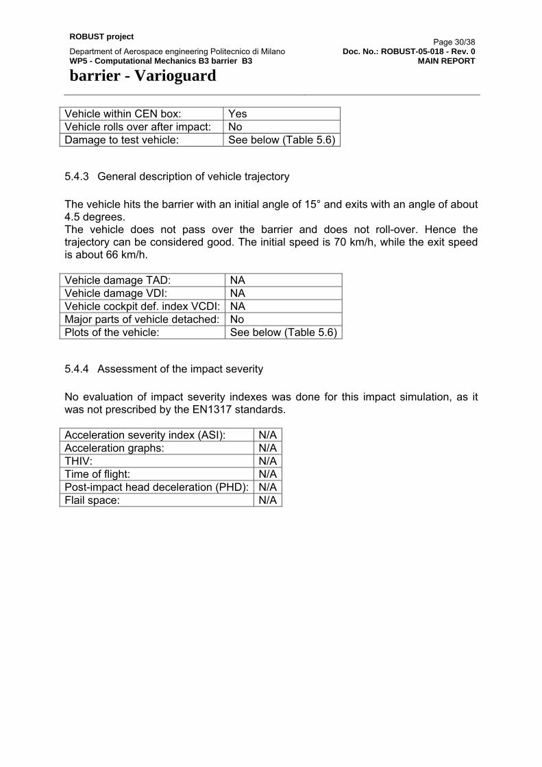
Vehicle within CEN box: Yes Vehicle rolls over after impact: No Damage to test vehicle: See below (Table 5.6)
5.4.3 General description of vehicle trajectory The vehicle hits the barrier with an initial angle of 15° and exits with an angle of about 4.5 degrees. The vehicle does not pass over the barrier and does not roll-over. Hence the trajectory can be considered good. The initial speed is 70 km/h, while the exit speed is about 66 km/h. Vehicle damage TAD: NA Vehicle damage VDI: NA Vehicle cockpit def. index VCDI: NA Major parts of vehicle detached: No Plots of the vehicle: See below (Table 5.6)
5.4.4 Assessment of the impact severity No evaluation of impact severity indexes was done for this impact simulation, as it was not prescribed by the EN1317 standards. Acceleration severity index (ASI): N/AAcceleration graphs: N/ATHIV: N/ATime of flight: N/APost-impact head deceleration (PHD): N/AFlail space: N/A

ROBUST project Page 31/38
Department of Aerospace engineering Politecnico di Milano Doc. No.: ROBUST-05-018 - Rev. 0 WP5 - Computational Mechanics B3 barrier B3 barrier - Varioguard
MAIN REPORT
5.4.5 Impact sequences and vehicle damage
Front view t=0.15 sec t=0.30 sec
t=0.45 sec t=0.60 sec
t=0.75 sec t=0.90 sec
Table 5.1

ROBUST project Page 32/38
Department of Aerospace engineering Politecnico di Milano Doc. No.: ROBUST-05-018 - Rev. 0 WP5 - Computational Mechanics B3 barrier B3 barrier - Varioguard
MAIN REPORT
Rear view t=0.15 sec t=0.30 sec
t=0.45 sec t=0.60 sec
t=0.75 sec t=0.90 sec
Table 5.2

ROBUST project Page 33/38
Department of Aerospace engineering Politecnico di Milano Doc. No.: ROBUST-05-018 - Rev. 0 WP5 - Computational Mechanics B3 barrier B3 barrier - Varioguard
MAIN REPORT
Top view t=0.15 sec t=0.30 sec
t=0.45 sec t=0.60 sec
t=0.75 sec t=0.9 sec
Table 5.3

ROBUST project Page 34/38
Department of Aerospace engineering Politecnico di Milano Doc. No.: ROBUST-05-018 - Rev. 0 WP5 - Computational Mechanics B3 barrier B3 barrier - Varioguard
MAIN REPORT
Side view t=0.15 sec t=0.30 sec
t=0.45 sec t=0.60 sec
t=0.75 sec t=0.90 sec
Table 5.4

ROBUST project Page 35/38
Department of Aerospace engineering Politecnico di Milano Doc. No.: ROBUST-05-018 - Rev. 0 WP5 - Computational Mechanics B3 barrier B3 barrier - Varioguard
MAIN REPORT
Isometric view t=0.15 sec t=0.30 sec
t=0.45 sec t=0.60 sec
t=0.75 sec t=0.90 sec
Table 5.5

ROBUST project Page 36/38
Department of Aerospace engineering Politecnico di Milano Doc. No.: ROBUST-05-018 - Rev. 0 WP5 - Computational Mechanics B3 barrier B3 barrier - Varioguard
MAIN REPORT
Vehicle damage Top Bottom
Right Left
Right Iso Left Iso
Table 5.6

ROBUST project Page 37/38
Department of Aerospace engineering Politecnico di Milano Doc. No.: ROBUST-05-018 - Rev. 0 WP5 - Computational Mechanics B3 barrier B3 barrier - Varioguard
MAIN REPORT
REFERENCES [1] EN 1317-1: Road restraint systems. Part 1: Terminology and general criteria
for test methods. European Committee for Standardization, 1998. [2] EN 1317-2: Road restraint systems. Part 2: Performance classes, impact test
acceptance criteria and test methods for safety barriers. European Committee for Standardization, 1998
[3] TR-2004-0107: Evaluation of small car vehicle model GM_R2. Force Technology Norway AS, Rev. A, December 2004.
[4] TR-2005-0012/ROBUST-05-010-Rev. 0: Evaluation of the 10 ton Rigid HGV FE-model. Force Technology Norway AS, Rev. 0, April 2005.
[5] OD-2000-0024. Force Technology Norway AS.