wp16 mmc test bench demonstrator deliverable 16.1 ... · wp16 – mmc test bench demonstrator...
TRANSCRIPT
PROMOTioN – Progress on Meshed HVDC Offshore Transmission Networks Mail [email protected] Web www.promotion-offshore.net This result is part of a project that has received funding form the European Union’s Horizon 2020 research and innovation programme under grant agreement No 691714. Publicity reflects the author’s view and the EU is not liable of any use made of the information in this report.
CONTACT
WP16 – MMC Test Bench Demonstrator
Deliverable 16.1: Definition and Specification of Test Cases

DOCUMENT INFO SHEET
Document Name: Deliverable 16.1: Definition and Specification of Test Cases
Responsible partner: RWTH
Work Package: WP 16
Work Package leader: RWTH
Task: Task 16.1
Task lead: RWTH
DISTRIBUTION LIST
PROMOTioN partners, European Commission
APPROVALS
Name Company
Validated by: 02.05.2018
19.05.2018
ABB
KUL
Task leader: Philipp Ruffing
WP Leader: Philipp Ruffing
DOCUMENT HISTORY
Version Date Main modification Author
1.0 19.05.2018 RWTH
2.0
WP Number WP Title Person months Start month End month
16 MMC Test Bench Demonstrator 106.8 M24 M48
Deliverable
Number Deliverable Title Type
Dissemination
level Due Date
16.1 Definition and Specification of Test Cases Report Public 30.04.2018

PROJECT REPORT
2
LIST OF CONTRIBUTORS
Work Package and deliverable involve a large number of partners and contributors. The names of the partners,
who contributed to the present deliverable, are presented in the following table.
PARTNER NAME
DNV GL Yin Sun, Yangtao Yang
KTH Ilka Jahn, Staffan Norrga
DTU Ömer Gösku, Nicolaos Cutululis
RWTH AACHEN Philipp Ruffing, Markus Kaiser, Matthias Quester, Fisnik Loku, Cora
Petino
UPV Ramon Blasco-Gimenez, Soledad Bernal-Perez
ØRSTED Lorenzo Zeni

PROJECT REPORT
3
EXECUTIVE SUMMARY
The objective of Work Package 16 of the PROMOTioN project is to demonstrate the operation and control of
meshed HVDC system using Power Hardware in the Loop (PHiL) and Controller Hardware in the Loop (CHiL)
through the use of real-time simulators (RTS) in order to increase the confidence in the feasibility of MTDC
operation. Moreover, the technology readiness level of state-of-the-art HVDC controls for meshed networks shall
be raised.
Within this deliverable, the test cases and scenarios that will be investigated in Work Package 16 are defined and
specified. These test cases cover the topics of the controllability and interoperability, fault handling and AC grid
support by meshed offshore DC grids. Additionally, resonance phenomena due to the harmonic interaction of
active components such as WPP and MMC and the grid will be studied in detail.
To ensure the link between the technical work packages – especially WP2, WP3 and WP4 – as well as the
standardisation efforts (WP11) and deployment plan of PROMOTioN (WP12), the test cases were discussed with
representatives of these work packages.

PROJECT REPORT
4
CONTENT
Document info sheet ............................................................................................................................................................. 1
Distribution list ..................................................................................................................................................................... 1
Approvals ............................................................................................................................................................................ 1
Document history ................................................................................................................................................................ 1
List of Contributors ............................................................................................................................................................... 2
Executive Summary .............................................................................................................................................................. 3
1 Introduction.................................................................................................................................................................... 1
1.1 Link to other PROMOTioN Work Packages ............................................................................................................ 4
1.2 Objective of this Deliverable .................................................................................................................................... 4
1.3 Overview about the planned Test Cases ................................................................................................................. 5
2 Detailed Definition and Specification of Test Cases .................................................................................................. 6
2.1 Controllability and Interoperability ........................................................................................................................... 6
2.1.1 Controllability of a Meshed DC Offshore Grid .................................................................................................. 6
2.1.2 Black Start Capability of HVAC and DRU-Connected Offshore Wind Farms .................................................. 7
2.1.3 Demonstration of the Interoperability of different Converters .......................................................................... 7
2.1.4 Cluster Control of Two/Three OWPPs Connected to the Same HVDC Converter .......................................... 8
2.1.5 Grid Forming OWPP Cluster (One or All Grid Forming) .................................................................................. 8
2.2 Fault Handling in Offshore Grids ............................................................................................................................. 9
2.2.1 Fault Clearing in Meshed DC Grids ................................................................................................................. 9
2.2.2 Fault Handling with Grid-Forming WTGs ....................................................................................................... 10
2.2.3 Offshore Symmetrical and Asymmetrical Faults ............................................................................................ 11
2.2.4 OWPP Response to DC Faults ...................................................................................................................... 11
2.3 Resonance Phenomena Studies ........................................................................................................................... 12
2.3.1 Unit Wind Turbine Converter Model for Resonance Phenomena Studies ..................................................... 12
2.3.2 Unit MMC Converter Model Validation for resonance phenomena Studies .................................................. 13
2.3.3 Offshore Wind Park Harmonic Resonance Analysis with AC Cable Connection .......................................... 14
2.3.4 Offshore Wind Park Harmonic Resonance Analysis with MMC-HVDC Connection ...................................... 15
2.3.5 Harmonic Impedance Analysis for DC Grids with DRU ................................................................................. 16
2.4 AC Grid Support .................................................................................................................................................... 17
2.4.1 Frequency Support by a Meshed Offshore Grid ............................................................................................ 17
2.4.2 Frequency Support and Power Oscillation Damping by OWPP Cluster ........................................................ 18
PROJECT REPORT
1
1 INTRODUCTION
Within the framework of modernisation of the European electricity grid, multi-terminal HVDC offshore grids
evacuating several gigawatts of wind from the Northern Seas shall be integrated into AC transmission systems.
Additionally, offshore MTDC systems might be used as interconnectors between large synchronous zone (e.g.
ENTSO-E, UK and the Nordic Grid). Such MTDC systems lead to novel challenges for transmission grid operators,
grid planners and manufacturers. Nevertheless, the experience regarding the operation of these systems as well
as their interaction with the AC transmission system and the offshore Wind Power Plants (WPP) is limited.
Within Work Package 16 of the PROMOTioN project, the operation and control of meshed HVDC system will be
investigated using Power Hardware in the Loop (PHiL) and Control Hardware in the Loop (CHiL) technology using
real-time simulators (RTS) in order to increase the confidence in the feasibility of MTDC operation.
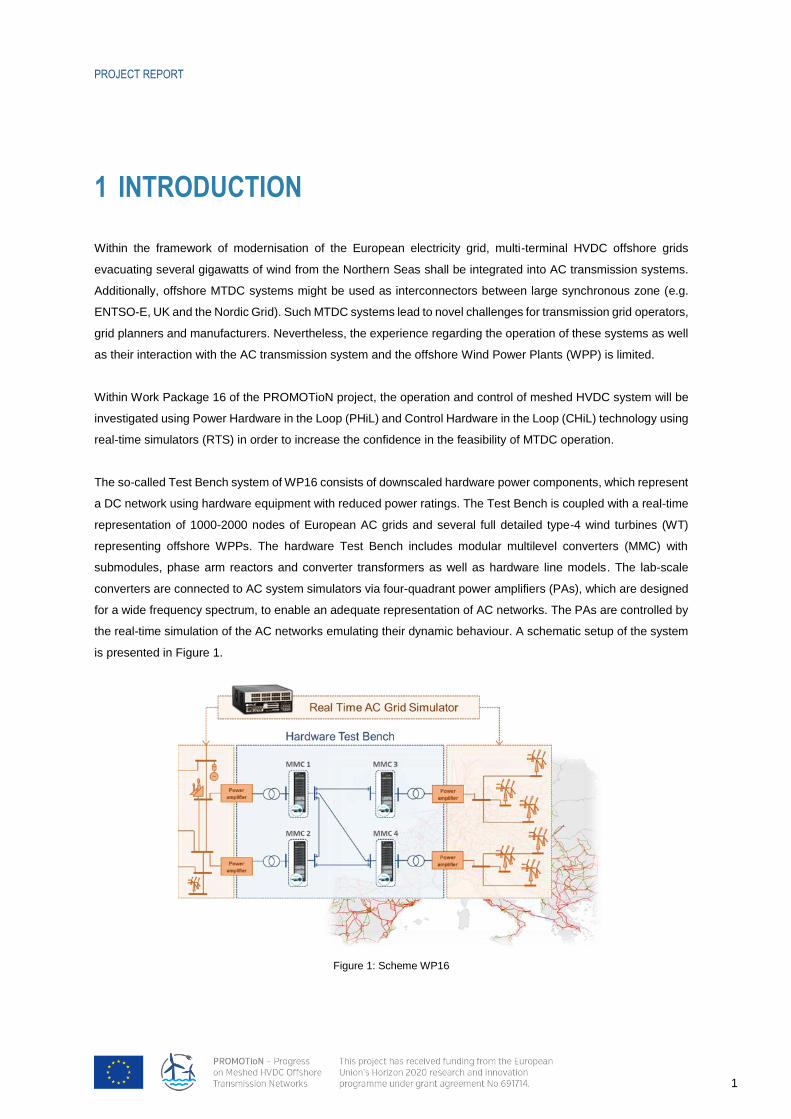
The so-called Test Bench system of WP16 consists of downscaled hardware power components, which represent
a DC network using hardware equipment with reduced power ratings. The Test Bench is coupled with a real-time
representation of 1000-2000 nodes of European AC grids and several full detailed type-4 wind turbines (WT)
representing offshore WPPs. The hardware Test Bench includes modular multilevel converters (MMC) with
submodules, phase arm reactors and converter transformers as well as hardware line models. The lab-scale
converters are connected to AC system simulators via four-quadrant power amplifiers (PAs), which are designed
for a wide frequency spectrum, to enable an adequate representation of AC networks. The PAs are controlled by
the real-time simulation of the AC networks emulating their dynamic behaviour. A schematic setup of the system
is presented in Figure 1.
Figure 1: Scheme WP16
PROJECT REPORT
2
A major advantage of the Test Bench system is its high flexibility. Thus, different control algorithms and protection
schemes can be tested in various network configurations and for different converter types (half-bridge and full-
bridge MMCs in monopolar or bipolar configuration). The system can also be used for the analysis of fault and
post-fault disturbances and interactions with the AC networks (large onshore AC grid and WPP).
Based on this technology the major objectives of WP16 are:
Demonstration of applicability of developed controls and simulation models of PROMOTioN
Technical and economical de-risking for the deployment and continuous operation of meshed HVDC-
systems
Improvement of certainness for road mapping process and standardization efforts
Therefore, realistic circumstances in the transmission and offshore system, e.g. operative incidents, disturbances
and faults will be investigated with the Test Bench system. The controllability of such a DC network will be
investigated in different network configurations (monopolar and bipolar DC networks) and with different converter
types (fault feeding and fault blocking converters). Moreover, the interoperability of different converter types within
the same grid will be investigated.
Additionally, the protection IED (intelligent electronic device) from WP4 shall be integrated into WP16´s Test
Bench. This protection IED will be pre-programmed to provide different protection algorithms (e.g. voltage
derivative) and protection strategies (e.g. fully selective). Specific timings and thresholds can be configured via a
MATLAB graphical user interface. To measure voltages and currents in the Test Bench, the IED´s hardware
interface is done via pluggable I/O modules that will be adapted to the specific requirements of the Test Bench.
The objective of the integration of the protection IED is the demonstration of the complete protection sequence in
the PHiL system (Measurement Detection Communication to breaker or/and converter Fault separation
Network recovery). Therefore, also a flexible small-scale breaker model based on solid-state switches and
arresters will be developed in WP16. The switching behaviour of different DC circuit-breakers is to be emulated
by controlling the switch. However, the breaker representation will not take into account possible transients that
might be introduced into the grid by specific breakers. Additionally, chopper models, which will be relevant for the
analysis of AC fault studies and pole re-balancing during DC faults, will be developed and integrated in the system.
The will be relevant for the analysis of AC fault studies and pole re-balancing during DC faults.
The interaction between large grid areas and interconnecting HVDC systems with respect to system stability shall
be studied in detail as well. The focus will be on the active power control and therefore on frequency control and
power oscillation damping. The modified active power exchange between asynchronous AC networks as well as
between OWPP and one AC network due to frequency supporting controllers or power oscillation damping
controllers will be investigated.
Another important aspect of WP16 is the analysis of harmonic stability problems related to resonance phenomena.
In the context of increasing renewable penetration in the power grid, network oscillations/incidents caused by the

PROJECT REPORT
3
adverse interaction between voltage source converters (VSCs) and power network have caught the attention of
transmission system operators (TSOs) worldwide. In Europe, harmonic oscillation between offshore wind turbine
converter and HVDC platform has been reported to cause significant delays in the offshore wind farm
development. For this reason, the leading offshore wind farm developers have already considered harmonic
stability as part of their overall project risk management. In China, large scale onshore wind farm connected to
the power grid via long transmission lines, in several occasions, also demonstrated the harmonic oscillation; both
state grid and CEPRI (China Electrical Power Research Institute) concerns the origin and solution to such
harmonic oscillation.
To address the issues related to the high penetration level of renewable integration worldwide, both CIGRE JWG
C4/B4.38 and IEC 61400-21-3 already formulated task forces to address the relevant technical challenges related
to the converter harmonic oscillations. The proposed research project under WP 16 of PROMOTioN aims to
execute input admittance measurement of wind turbine converter from leading wind turbine manufacturer in the
CHIL (Controller Hardware in the Loop) concepts. The derivation of linearized input admittance of unit VSC device
is essential for the harmonic stability study, where multiple VSCs and passive grid components are interacting in
complex manner. The test results will provide guidelines on the test procedures applicable to the MW industrial
level applications and produce material/content for the future development of international standards and
recommended practice. Therefore, the Flexible Power Grid Laboratory (FPGL) of DNV GL will be used in this
project to enable innovative testing and model validation of DER equipment, such as wind turbine converter. The
test facility is one of a few that allows testing of the correct functioning of distributed energy resource unit under
realistic condition in a system. It verifies the hardware (power parts) and the control (ICT) simultaneously to
validate that a DER unit is ready to be integrated into a larger system (e.g. the energy grid). The FPGL lab is the
only facility able to test this combination on medium voltage level (up to 24 kV) and high-power level (up to 1
MVA). The main purpose of FPGL testing is to de-risk equipment and ensure flawless operation in a real grid. The
FPGL includes a facility for HIL testing with RTS and power amplifier (0 – 200 KVA). The FPGL is part of the DER-
LAB Network of Excellence and takes part in EU project on R&D infrastructures like DERLAB (FP6), DERRI (FP7)
and EriGrid (H2020).
To demonstrate the operation of DRU-enabled wind turbine control systems in an HVDC grid the construction of
a real-time prototype demonstrator with actual control (CHiL) and protection hardware will be done in WP16. The
objective is to conduct behavioural tests according to the previously defined test cases (in WP2 and WP3) and to
validate the applicability of different systemic/technological options. A key aspect is to test the fault handling in
AC grid based on grid forming WTGs. Therefore, a commercial AC protection relay will be tested in a DRU
connected AC network in the DRU CHiL system.
The overall goal of the WP is to increase the confidence in the control of meshed DC grid and to raise its
technological readiness level. Thereby, the studies of WP16 will contribute to develop appropriate principles and
operation strategies, which enable a smooth interoperability between different components and technologies of
future meshed HVDC offshore grids.
PROJECT REPORT
4
1.1 LINK TO OTHER PROMOTION WORK PACKAGES
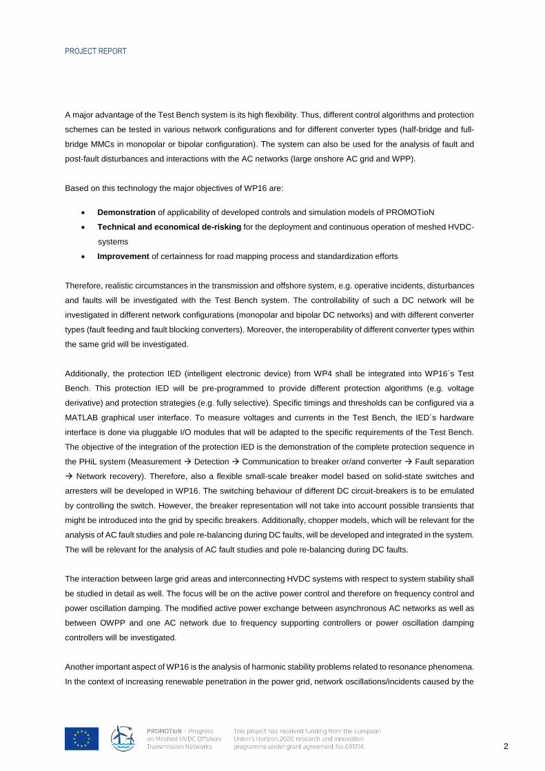
An important aspect of WP16 is to demonstrate the knowledge gained in the technical work packages of
PROMOTioN. This includes grid operation and control concepts for meshed and DRU connected DC networks
from WP2, wind turbine and wind power plant control concepts and models from WP3 and protection strategies
from WP4. Additionally, it is an objective of WP16 to integrate the protection IED developed in WP4 into the Test
Bench System.
Figure 2: Link to other PROMOTioN work packages
The findings of WP16 will be used as in input for WP11 and WP12, to contribute to the standardisation efforts and
the elaboration of a roadmap for future meshed offshore DC networks.
1.2 OBJECTIVE OF THIS DELIVERABLE
The objective of this deliverable is to define and specify the test cases, which will be conducted in Work
Package 16. Moreover, a high-level overview of the scenario variations for each test case is provided.
To ensure the link between the technical work packages – especially WP2, WP3 and WP4 – as well as the
deployment plan of PROMOTioN (WP12) the test cases have been presented to the work packages. Based on
the feedback from the other WPs the test cases were re-evaluated and finalised by the partners of WP16.
Additionally, the origin of each test cases is described and a motivation is provided. Even though all defined test
cases and all scenarios are worth to investigate, the significance of each test case is rated as “mandatory” or
“optional”, in order to provide the most relevant results for the given amount of time.
Since the investigations of WP16 will be conducted in three different laboratories – the MMC Test Bench at the
RWTH Aachen, RTS and WT-Replica at DNV GL Arnhem and the DRU CHiL at the UPV – the location as well
as the main responsibility is specified for each test case.

PROJECT REPORT
5
1.3 OVERVIEW OF THE PLANNED TEST CASES
The Test Cases, which will be conducted in WP16 are categorised into four major topics:
Controllability and Interoperability
Fault Handling in Offshore Grids
Resonance Phenomena
AC Grid Support
An overview of the test cases is provided in Table I, whereas the detailed definition is presented in section 2.
Table I: Overview of the defined test cases of WP16
Controllability and Interoperability
Fault Handling in Offshore Grids
Resonance Phenomena
AC Grid Support
Controllability of a Meshed DC Offshore Grid
Fault Clearing in Meshed DC Grids
Unit MMC Turbine Converter Model Validation for Resonance Phenomena Studies
Frequency Support by a Meshed Offshore Grid
Black Start Capability of HVAC and DRU-Connected Offshore Wind Farms
Fault Handling with Grid Forming WTGs
Unit MMC Converter Model Validation for Resonance Phenomena Studies
Frequency Support and Power Oscillation Damping by OWPP Clusters
Demonstration of the Interoperability of Different Converters
Offshore Symmetrical and Asymmetrical Faults
Offshore Wind Park Harmonic Resonance Analysis with AC Cable Connection
Cluster Control of Two/Three OWPPs Connected to the Same HVDC Converter
OWPP Response to DC Faults
Offshore Wind Park Harmonic Resonance Analysis with MMC-HVDC Connection
Grid Forming OWPP Cluster (One or All Grid Forming)
Harmonic Impedance Analysis for DC Grids with DRU

PROJECT REPORT
6
2 DETAILED DEFINITION AND SPECIFICATION OF TEST CASES
2.1 CONTROLLABILITY AND INTEROPERABILITY
An important part of work package 16 is the demonstration of the general controllability of meshed offshore grids.
Therefore, the generic control algorithms developed in WP2 will be transferred on the controllers of the test bench
system and their functionally will be tested. These “normal operation” test cases will be the foundation for the
other test cases, i.e. the fault studies. The test cases include the controllability of the DC grid and the offshore
wind power plant. A special focus is given to the control of grid forming wind turbines.
2.1.1 CONTROLLABILITY OF A MESHED DC OFFSHORE GRID
Test Case Motivation Origin Significance
Within WP1 and WP2 different configurations and topologies for offshore grids are identified. These shall be investigated in WP16 in regard to the controllability of the DC system. Moreover, interaction with the offshore WPPs and the onshore AC grid shall be analysed.
A first goal of WP16 is the confirmation of proposed control strategies and thereby improve the TRL of common converter control principles.
WP1, WP2
Mandatory
Test Case Definition
The objectives of the investigations are:
Controllability demonstration of the converters (half-bridge and full-bridge) in a meshed grid connected to Wind Power Plants. Based on these, it is one objective of WP16 to point out the difference between the PHIL system and EMT simulation. Based on the lessons learned, recommendations for future simulation models will be provided.
Controllability demonstration of different converter configurations within one meshed HVDC grid
Controllability demonstration of different grid topologies (p2p, radial, meshed)
Specification of the relevant scenarios Significance
Half-bridge and full-bridge converters
Monopolar DC System (WP2 Minimal Meshed Network)
Bipolar DC System (WP2 Minimal Meshed Network)
Change of power flow set-point changes
Change of wind infeed changes
Change of AC grid use-case (share of RES, Load) From WP2
Network layout/extension
Mandatory
Mandatory
Mandatory
Mandatory
Mandatory
Optional
Optional
Physical location and the simulation environment Main Responsibility
Aachen – Test Bench System with RTS RWTH

PROJECT REPORT
7
2.1.2 BLACK START CAPABILITY OF HVAC AND DRU-CONNECTED OFFSHORE WIND FARMS
Test Case Motivation Origin Significance
Developed grid forming controllers for DRU connection of offshore wind farms have been shown to have good performance during islanding operation and also when connecting and re-synchronising to a very weak HVAC-grid (umbilical). The feasibility of the extension of these controllers to black and brown start operation will be studied in this test case using a real-time CHiL set up.
WP2, WP3
Mandatory
Test Case Definition
The objectives of the investigations are:
Validation of strategies for offshore wind farm self-start operation using CHIL for the WTG controller and for the OWF controller and using detailed OWF models.
Validation of synchronization strategies to a weak on-shore ac-grid.
Specification of the relevant scenarios Significance
Offshore wind farm self-start with limited energy storage.
Case a: HVAC export cable and HVAC transformer energisation and synchronisation to a weak grid (brown start) or to an unenergised grid (black start).
Case b: DRU transformers, filters and HVDC cable energisation and on-shore MMC converter connection to a weak grid (brown start) or to an unenergised grid (black start).
Mandatory
Mandatory
Mandatory
Physical location and the simulation environment Main Responsibility
Valencia – CHIL Prototype demonstrator UPV
2.1.3 DEMONSTRATION OF THE INTEROPERABILITY OF DIFFERENT CONVERTERS
Test Case Motivation Origin Significance
In the future, different converters might be used in the same DC network. These are mainly classified as fault feeding and fault blocking converters.
A demonstration of the interoperability of these converter types and the controllability of such a DC network shall be conducted in WP16.
WP1, WP2, WP4
Optional
Test Case Definition
In WP16 the different converter types (fault feeding and fault blocking converters) will be represented using most established designs – half- and full-bridge Modular Multilevel Converters.
The objectives if this test case is the demonstration of the control interoperability of fault feeding and fault blocking converters. However, this normal operation test case is mainly the foundation for the interoperability investigations of different fault clearing strategies in test case 2.2.1 – scenario: Interoperability of fault clearing methods.
The detailed scenarios for the interoperability of different converter types will be defined in collaboration with WP2 and WP4

PROJECT REPORT
8
Specification of the relevant scenarios Significance
Monopolar DC System (WP2 Minimal Meshed Network)
Bipolar DC System (WP2 Minimal Meshed Network)
Change of power flow set-point changes
Network layout/extension
Optional
Optional
Optional
Optional
Physical location and the simulation environment Main Responsibility
Aachen – Test Bench System with RTS RWTH
2.1.4 CLUSTER CONTROL OF TWO/THREE OWPPS CONNECTED TO THE SAME HVDC CONVERTER
Test Case Motivation Origin Significance
In WP3, test cases as “detailed models for multiple WPPs each with multiple wind turbines connected to the same HVDC converter” have been described. Today there are many installations of WPP clusters; however, grid codes for these clusters are not well-defined.
WP3
Optional
Test Case Definition
The objectives of the investigations are:
To demonstrate cluster and WPP level control solutions
To demonstrate compliance with the “new” grid codes (that will be recommended)
Specification of the relevant scenarios
Set-Point Changes
Wind infeed changes
Disconnection of one of the WPPs
Optional
Optional
Optional
Physical location and the simulation environment Main Responsibility
Aachen – Test Bench System with RTS DTU
2.1.5 GRID FORMING OWPP CLUSTER (ONE OR ALL GRID FORMING)
Test Case Motivation Origin Significance
Grid forming WT control strategies have been developed and tested in simulations mainly in WP3, where several wind power plants (hence wind turbine converters) are connected in parallel. However, the demonstration of these control strategies on real converters has not been performed in the project. The motivation is to demonstrate the grid forming capability of wind turbine converters when they are in parallel operation, whereas all or one of the wind power plants are in grid forming mode.
WP3 Mandatory
Test Case Definition
The objectives of the investigations are:

PROJECT REPORT
9
To experimentally demonstrate synchronized operation of several wind turbine converters in grid forming mode
To experimentally demonstrate the stability of parallel connected OWPPs with different control strategies, grid forming and grid following
Specification of the relevant scenarios Significance
Energization of the offshore AC network by the OWPP(s), i.e. grid forming wind turbine converters
Disconnection and re-connection of wind turbine converter(s) to the offshore AC network, formed by one or more grid forming wind turbines
The offshore MMC controlling active and reactive power towards the DC link (not offshore grid forming)
Mandatory
Mandatory
Mandatory
Physical location and the simulation environment Main Responsibility
Aachen – Test Bench System with RTS DTU
2.2 FAULT HANDLING IN OFFSHORE GRIDS
Another important part of WP16 is the demonstration of protection in particular fault clearing methods. Although
simplifications have to be made in a down-scaled laboratory testbench (pi-links instead of cables, converter with
less number of cells), the functionality of protection chain (fault clearing) will be tested and analysed for several
cases and scenarios. Therefore, the protection IED developed in WP4 will be modified and included in the Test
Bench system. If possible, implications of fault handling on operation of HVDC offshore grids and wind power
plants will be derived.
2.2.1 FAULT CLEARING IN MESHED DC GRIDS
Test Case Motivation Origin Significance
A set of relevant DC fault clearing strategies is defined and studied with regard to selectivity, speed, robustness, requirements on backup protection and requirements on post-fault restoration for VSC-based grids in WP4.
Moreover, these strategies and their impact on DC grid components as well as their impact on the AC grid and the WPPs are studied in WP2.
In standard offline EMT simulation the level of detail of the onshore AC networks and the WPP is usually limited, due to long simulation times. A main advantage of the PHiL and RTS is the opportunity to analyse the combined AC and DC system behaviour (using detailed EMT models) in different cases. Therefore, the interaction between the systems will be studied within WP16.
The findings from WP2 and WP4 shall be confirmed by the studies on the Test Bench system in WP16
WP2, WP4
Mandatory
Test Case Definition
In WP16, DC Fault Clearing Strategies defined by WP4 shall be investigated in the test bench system in combination with the real-time representation of the AC onshore grid and the offshore wind power plants. The AC models will have a higher level of detail compared to the models used in standard EMT simulations. The fault detection and discriminations as well as the breaker control will be represented by the protection IED developed in WP4. The main objective is to improve the TRL of the fault clearing strategies.

PROJECT REPORT
10
The objectives of the investigations are:
Analysis of converter controllability during DC fault (internal energy management, STATCOM operation, reconnection/restart after temporary blocking for HB and FB MMCs)
Interaction analysis of fault clearing strategies with offshore WPPs (with a number of WTs modelled in full detail)
Interaction analysis of fault clearing strategies with onshore AC grid and AC grid stability (transient stability, frequency stability)
Analysis of the usability of the protection IED in the PHiL system. This include the influence of single-ended / double-ended protection methods.
Specification of the relevant scenarios Significance
Monopolar DC System (WP2 Minimal Meshed Network)
Bipolar DC System (WP2 Minimal Meshed Network)
Variety of different fault scenarios (Location, Type, Resistance) o AC Onshore Faults o DC Grid Fault o AC Offshore Grid Faults
Ground schemes
Network topology variations
Load flow variations Different use cases
Fault detection algorithm (WP4 single-ended / double-ended)
Breaker technology (fast, slow)
IED busbar communication
Interoperability of fault clearing methods (e.g. HB-MMC with DCCB and FB-MMC with HSS)
Mandatory
Mandatory
Mandatory
Optional
Optional
Optional
Mandatory
Mandatory
Optional
Optional
Physical location and the simulation environment Main Responsibility
Aachen – Test Bench System with RTS RWTH
2.2.2 FAULT HANDLING WITH GRID-FORMING WTGS
Test Case Motivation Origin Significance
WTG controllers developed in WP3 for DRU use are all grid forming, as well as those used in WP16 test case 2.1.2 for basic black-start operation. However, fault handling with this kind of grid forming wind turbine controllers needs to be studied in realistic conditions.
WP2, WP3
Mandatory
Test Case Definition
The objectives of the investigations are:
Demonstration of offshore ac grid fault clearing strategies in systems employing grid forming converters in islanded operation
Demonstration of offshore ac grid fault clearing strategies in systems employing grid forming converters with DRU-HVDC connection
Grid forming converter contribution to on-shore grid fault handling
Therefore, different AC fault scenarios will be conducted and analysed.
Specification of the relevant scenarios Significance
Offshore grid faults (with variation of the fault type) with islanded grid-forming wind turbine generators
Mandatory

PROJECT REPORT
11
Offshore grid faults with DRU-HVDC connected grid forming WTGs
On-shore grid faults with HVAC connected grid forming WTGs
On-shore grid faults with DRU-HVDC connected grid forming WTGs
Mandatory
Mandatory
Mandatory
Physical location and the simulation environment Main Responsibility
Valencia – Prototype demonstrator UPV
2.2.3 OFFSHORE SYMMETRICAL AND ASYMMETRICAL FAULTS
Test Case Motivation Origin Significance
The offshore symmetrical and asymmetrical faults are being studied in PROMOTioN and also by manufacturers. The grid codes for these faults are not mature enough. There is the need for detailed recommendations for grid code requirements (both for the HVDC and wind turbines). The demonstration of faults will decrease the risk of inaccurate requirements.
WP2, WP3
Optional
Test Case Definition
The objectives of the investigations are:
Analysis of offshore faults in a converter dominated offshore network
Demonstration of HVDC and WPP fault responses
Demonstration of recommended grid code requirements
Specification of the relevant scenarios Significance
Only the HVDC converter is connected - securely cleared fault
Both the HVDC and WPP converter are connected - securely cleared fault
The WPP is securely disconnected due to failure of fault clearance
Mandatory
Mandatory
Mandatory
Physical location and the simulation environment Main Responsibility
Aachen – Test Bench System with RTS DTU
2.2.4 OWPP RESPONSE TO DC FAULTS
Test Case Motivation Origin Significance
DC faults are mostly being investigated in terms of clearing strategies. The response of OWPP plays an important role as it will impact the eventual loss of infeed. For instance, if the OWPP can stay connected for “long“ duration of DC faults, then the loss of infeed would be decreased.
WP2, WP3, WP4
Mandatory
Test Case Definition
The objectives of the investigations are:
Analysis of OWPP – HVDC converter interaction during DC faults
Analysis OWPP response as a function of DC fault clearing duration
Demonstration of OWPP robustness during DC faults
Demonstration of recommended requirements for OWPP DC fault response

PROJECT REPORT
12
Specification of the relevant scenarios Significance
Monopolar DC System (WP2 Minimal Meshed Network)
Bipolar DC System (WP2 Minimal Meshed Network)
Fault Blocking (Full-Bridge) Converter
Fault Feeding (Half-Bridge) Converter in combination with and without DC-CBs
Variety of different fault scenarios (Location, Type, Resistance)
Network topology variations
Load flow variations Different use cases
Mandatory
Mandatory
Mandatory
Mandatory
Mandatory
Optional
Optional
Physical location and the simulation environment Main Responsibility
Aachen – Test Bench System with RTS DTU
2.3 RESONANCE PHENOMENA STUDIES
Using the impedance based models, harmonic stability problems related to resonance phenomena can be
predicted in the frequency domain. For this, the frequency response of the developed impedance models will be
validated by means of comparisons with time domain simulations and laboratory results of the test bench system.
Furthermore, the harmonic stability and potential interactions of active components and the passive grid will be
studied by means of the developed models.
2.3.1 UNIT WIND TURBINE CONVERTER MODEL FOR RESONANCE PHENOMENA STUDIES
Test Case Motivation Origin Significance
The test case focuses on the development of a frequency domain converter model for wind turbines and verifies the frequency domain results with the time domain simulation/test results obtained from a unit wind turbine converter. The test case is intended to validate the derived analytical impedance model and the wind turbine converter model. A simple test circuit of wind turbine connected to the physical voltage source via the pre-defined grid impedance is planned.
WP16 mandatory
Test Case Definition
Objective:
Extract the frequency behaviour of wind turbine converters using the test bench in Arnhem and compare it to the prediction of the analytical wind turbine converter model.

PROJECT REPORT
13
Specification of the relevant scenarios Significance
Small signal perturbation test using the amplifier operated as voltage source (perturbation signal is directly injected to the amplifier input)
Small signal perturbation test using the amplifier operated as current source parallel injection.
Power Hardware in the loop test to be performed
Mandatory
Mandatory
Mandatory
Physical location and the simulation environment Main Responsibility
Arnhem – Flexible Power Grid Lab DNV GL
2.3.2 UNIT MMC CONVERTER MODEL VALIDATION FOR RESONANCE PHENOMENA STUDIES
Test Case Motivation Origin Significance
The test case centres on the development of a frequency domain MMC converter model and verifies the frequency domain results with the time domain simulation/test results obtained from a single MMC testbench unit. A simple test circuit of one MMC testbench unit connected to the physical voltage source via the pre-defined grid impedance is planned.
WP16 mandatory
Test Case Definition
Objective:
PROJECT REPORT
14
Extract the frequency behaviour of an MMC converter using the test bench and compare it to the prediction of the analytical MMC model in the frequency domain.
For the validation, the scaled test bench will be used as rectifier in dc voltage control and connected to a load. As preliminary study, the real-time simulator can be used for the frequency response of a full-scaled MMC model.
Specification of the relevant scenarios Significance
Small signal perturbation test using the amplifier operated as voltage source (perturbation signal is directly injected to the amplifier input)
Unit MMC converter operated as STATCOM mode or inverter/rectifier mode of typical MMC-HVDC node
Mandatory
Mandatory
Physical location and the simulation environment Main Responsibility
Aachen – RTS DNV GL
2.3.3 OFFSHORE WIND PARK HARMONIC RESONANCE ANALYSIS WITH AC CABLE CONNECTION
Test Case Motivation Origin Significance
Utilizing the frequency domain impedance based model of wind turbine unit (developed and validated in DNV GL Arnhem Test Lab with manufacture replica –test case 2.3.1) and MMC converter (developed and validated by test case 2.3.2), this test case investigates the system level harmonic resonance risk with respects to an AC cable connection.
The MMC testbench will be connected with time domain real-time RT-LAB model of wind turbine (via power amplifiers), and time domain real-time AC/DC grid model (via power amplifiers). The harmonic resonance prediction in the frequency domain will be verified against the time domain power hardware in the loop test results.
WP16 Optional
Test Case Definition
Objective:
Validate the harmonic resonance prediction using the impedance based stability criteria with time domain results concerning an offshore wind park connection via AC cable.

PROJECT REPORT
15
Specification of the relevant scenarios Significance
Offshore wind park AC collection grid + Wind turbine + AC export cable will be represented in the RT-LAB real-time simulation environment and interface to the MMC testbench unit operated as STATCOM via a power amplifier. The onshore AC grid will be modelled in RT-LAB real-time simulation environment as well and interfaced to the same onshore node where STATCOM and export cable of wind-park are connected.
Wind farm start-up sequence (i.e. Stability of MMC STATCOM)
Wind farm normal operation stability assessment (i.e. Wind Turbine, STATCOM and Grid Interaction)
Optional
Optional
Optional
Physical location and the simulation environment Main Responsibility
Aachen – RTS DNV GL
2.3.4 OFFSHORE WIND PARK HARMONIC RESONANCE ANALYSIS WITH MMC-HVDC CONNECTION
Test Case Motivation Origin Significance
Utilizing the frequency domain impedance based model of a wind turbine unit (developed and validated in DNV GL Arnhem Test Lab with manufacture replica –test case 2.3.1) and MMC converter (developed and validated by test case 2.3.2, this test case investigates the system level harmonic resonance risk with respects to MMC-HVDC
The MMC testbench will be connected with the time domain real-time RT-LAB model of the wind turbine (via power amplifier), and the time domain real-time AC grid model (via power amplifier). The harmonic resonance prediction in the frequency domain will be verified against the time domain power hardware in the loop test results.
WP16 Mandatory
Test Case Definition
Objective:

PROJECT REPORT
16
Comprehensive study regarding harmonic resonance with respect to different offshore grid states (e.g. number of connected wind turbines, different power in-feed). The study will be done by means of the impedance based stability criteria.
Validate the harmonic resonance prediction by the impedance based stability criteria with time domain results concerning an offshore wind park connection via MMC-HVDC platform
Specification of the relevant scenarios Significance
Wind farm normal operation stability assessment (i.e. Wind Turbine, MMC-HVDC interaction)
Offshore wind park AC collection grid + Wind turbine will be represented in the RT-LAB real-time simulation environment and interface to the MMC testbench unit operated as MMC-HVDC platform via power amplifier. The onshore AC grid will be modelled in RT-LAB real-time simulation environment as well and interfaced to the same onshore MMC-HVDC station represented by MMC testbench via power amplifier.
Wind farm start-up sequence (i.e. MMC-HVDC and AC grid interaction)
Mandatory
Optional
Optional
Physical location and the simulation environment Main Responsibility
Aachen – RTS DNV GL
2.3.5 HARMONIC IMPEDANCE ANALYSIS FOR DC GRIDS WITH DRU
Test Case Motivation Origin Significance
Grid forming WTGs are required for islanded operation, DRU operation, in some black-start strategies and also improves the characteristics of HVAC and MMC-HVDC connected wind farms.
WP3 Mandatory

PROJECT REPORT
17
This test case aims at verifying the validity of frequency domain models for the harmonic stability of offshore wind power plants consisting of grid forming WTGs.
Test Case Definition
Objectives:
Study the validity of existing frequency domain impedance techniques for harmonic stability analysis of grid forming offshore wind farms.
Validate in a real-time CHIL the frequency domain models obtained analytically.
Specification of the relevant scenarios Significance
Harmonic resonance analysis of islanded WPPs with grid forming/mixed WTGs
Harmonic resonance analysis of HVAC connected WPPs with grid forming WTGs
Harmonic resonance analysis of DRU-HVDC connected WPPs with grid forming WTGs
Mandatory
Mandatory
Mandatory
Physical location and the simulation environment Main Responsibility
Valencia – Prototype demonstrator UPV
2.4 AC GRID SUPPORT
The high controllability of multi-terminal HVDC systems opens up a wide variety of possibilities for ac network
support. The question on how to use this potential is subject of many publications. The following test cases shall
investigate the frequency support between asynchronous ac systems using multi-terminal HVDC systems as well
as the frequency support of connected OWPP. Additionally, the potential of power oscillation damping using
OWPP can be demonstrated.
2.4.1 FREQUENCY SUPPORT BY A MESHED OFFSHORE GRID
Test Case Motivation Origin Significance
Using the Test Bench System with RTS it can show, that the frequency support strategies investigated in WP2 are realistic and functional.
WP1, WP2 Mandatory
Test Case Definition
In WP2 the possibilities of different control algorithms for frequency support are analysed. The results shall be compared to the results of a “lab scale” representation in combination with reduced AC grids by means of node numbers. The reduction of the adjacent AC grids is necessary because of the limited computing power of the test bench system. Nevertheless, the modelling of each ac node due to the used EMT models is more detailed compared to the simulations of WP2.
1. Frequency support control by decentralized droop controllers using the dc voltage as communication medium.
2. Frequency support control by centralized (“master”) control using optical fibre based communication
The frequency deviations will be simulated based on the loss due to an n-1 fault.
Specification of the relevant scenarios Significance

PROJECT REPORT
18
The impact of different share of RES as well as different load situations shall be analysed in WP2. The associated scenarios in WP2 shall be transferred to the scenarios of WP16.
DC Grid connected to one detailed synchronous zone (e.g. ENTSO-E) and one simplified synchronous zone (single bus network)
DC Grid connected to a different detailed synchronous zone (e.g.GB) and one simplified synchronous zone (single bus network)
DC Grid connected to two separate detailed synchronous zones (e.g. ENTSO-E and GB)
DC Grid connected to one detailed synchronous zone (e.g. ENTSO-E) and one offshore wind power plant (OWPP) (in collaboration with 2.4.2)
Mandatory
Optional
Optional
Optional
Physical location and the simulation environment Main Responsibility
Aachen – Test Bench System with RTS RWTH
2.4.2 FREQUENCY SUPPORT AND POWER OSCILLATION DAMPING BY OWPP CLUSTER
Test Case Motivation Origin Significance
In the ENTSO-E HVDC NC Article 39 (1); “a DC-connected power park module shall be capable of receiving a fast signal from a connection point in the synchronous area to which frequency response is being provided and be able to process this signal within 0.1 seconds from sending to completion of processing the signal for activation of the response. Frequency shall be measured at the connection point in the synchronous area to which frequency response is being provided”.
Compliance with this requirement should be demonstrated.
Additionally, “Article 39 Frequency stability requirements 2. (b) DC-connected power park modules connected via HVDC systems which connect with more than one control area shall be capable of delivering coordinated frequency control as specified by the relevant TSO”
WP1, WP2, WP3
Optional
Test Case Definition
The objectives of the investigations are:
Demonstration of OWPP frequency support and POD capabilities to the onshore grid/s
Demonstration of cluster control functionalities mastering the OWPPs for frequency support and POD, provided to more than one onshore control area.
Specification of the relevant scenarios Significance
The technical feasibility of impact of frequency support and POD by OWPP shall be investigated in the following scenarios:
DC point-to-point connection between one detailed synchronous zone (e.g. ENTSO-E) and one offshore wind power plant (OWPP)
DC Grid connected to one detailed synchronous zone (e.g. ENTSO-E) and one offshore wind power plant (OWPP)
The detailed scenario layout will be developed in close contact with test case 2.4.1 and WP2
Optional
Optional
Physical location and the simulation environment Main Responsibility
Aachen – Test Bench System with RTS DTU