workshop manual bpw leaf spring suspensions, vb · 1000 leaf spring 1010 spring screw 1011 hexagon...
TRANSCRIPT
Workshop manualBPW leaf spring suspensions, VB
VB
BPW-WH-VB 35431501e

BPW-WH-VB 35431501ePage 2
Valid: 01.07.2015
4th edition
Subject to change without notice.
Current versions and additional information can be found online at www.bpw.de.

BPW-WH-VB 35431501e Page 3
Contents
1. Product identifi cation ..................................................................................................................... Page 4
1.1 Explanation of BPW axle type codes (extract) Page 4 1.2 Explanation of BPW code numbers (extract) Page 5
2. Special tools .................................................................................................................................... Page 6
3. Exploded view / name ..................................................................................................................... Page 9
4. Tightening torques ........................................................................................................................ Page 13
5. Safety regulations, safety information ......................................................................................... Page 14
5.1 Safety regulations Page 14 5.2 Safety information Page 15
6. Care and maintenance .................................................................................................................. Page 16
7. Removing and installing axle with leaf springs ........................................................................... Page 22
7.1 Removing Page 22 7.2 Replacing the bushes in the connecting rods Page 24 7.3 Installing Page 27
8. Removing and installing U-stabilser ............................................................................................ Page 30
9. Removing and installing leaf springs ........................................................................................... Page 33
10. Removing and installing equalising beam ................................................................................... Page 35
10.1 Removing equalising beam Page 35 10.2 Replacing bronze bushes Page 37 10.3 Replace the rubber-steel bush Page 38 10.4 Install equaliser beam Page 39
11. Axle alignment check .................................................................................................................... Page 44
12. Axle alignment check with laser measuring devices ................................................................. Page 48
- Refer to appropriate workshop manuals for axle repairs

BPW-WH-VB 35431501ePage 4
1 Product identifi cation
1.1 Explanation of BPW axle type codes (extract)
Example:
HSF VB U LL 2/ 12010 /12° M ECO Plus 2 ECO Cargo
HSF Example for axle typeVB Mechanical suspension without braking load
compensation, leaf springs above the axleVBN Mechanical suspension without braking load
compensation, leaf springs above the axle, low design, only with VB ECO Cargo
VBT Mechanical suspension without braking load compensation, leaf springs below the axle
U With U-stabiliserL With steering axle, series L,
steering angle max. 40°LL With self-steering axle, series LL,
steering angle max. 27°- Single axle2/ Tandem axle suspension3/ Tri-axle suspension
6006 to20010
Axle load (kg) + quantity of wheel studs per hub
/12° to
/40°
Steering angle of steering axle
B ReinforcedBE Reinforced,
equaliser bearing with bronze bushesE Equaliser bearing with bronze bushesHD Heavy duty versionHDE Heavy duty version
equaliser bearing with bronze bushesK Weight-optimized versionKE Equaliser bearing with bronze bushesKN Low construction heightL ReinforcedLE Reinforced,
equaliser bearing with bronze bushesM ReinforcedME Reinforced,
equaliser bearing with bronze bushesMN Reinforced, low construction heightMNE Reinforced, low construction height,
equaliser bearing with bronze bushesECO Plus 2 BPW trailer axle with ECO Plus 2 UnitECOPlus BPW trailer axle with ECOPlus UnitECO MAXX Weight-optimized BPW trailer axle with
ECO UnitMAXX Weight-optimized BPW trailer axle with
conventional hub bearing systemECO BPW trailer axle with ECO Unit
ECO Cargo New running gear system as from 2013

BPW-WH-VB 35431501e Page 5
1.2 Explanation of BPW code numbers (extract)
Example:
32. 58. 744. 018
1. + 2. digit
21. Single axle with suspension parts
28.
30.
38.
22. Tandem axle suspension
23. Tri-axle suspension / Four axle suspension / Five axle suspension
32. Tandem axle suspension / Tri-axle suspension / Four axle suspension / Five axle suspension
39. Tri-axle suspension / Four axle suspension / Five axle suspension
3. + 4. digit
Axle load Roller bearings Hub bearing system
06. 6500 kg 33116 / 32310 Conventional hub bearing system
08. 8000 - 9000 kg 33116 / 32310
09. 8000 - 9000 kg 33116 / 32310
10. 10000 - 12000 kg 33118 / 33213
14. 13000 - 14000 kg 32219 / 33215
16. 16000 - 18000 kg 32222 / 32314
20. 20000 kg 32224 / 32316
36. 6500 kg 33116 / 32310 ECO / ECO-MAXX Unit
38. 8000 - 9000 kg 33116 / 32310
40. 10000 - 12000 kg 33118 / 33213
44. 13000 - 14000 kg 32219 / 33215
48. 8000 - 9000 kg 33118 / 33213 ECOPlus Unit
49. 8000 - 9000 kg 33118 / 33213
50. 10000 - 12000 kg 33118 / 33213
51. 10000 - 12000 kg 33118 / 33213
56. 6500 - 7000 kg 33118 / 33213 ECO Plus 2 Unit
58. 8000 - 9000 kg 33118 / 33213
59. 8000 - 9000 kg 33118 / 33213
65. 6400 kg 33215 / 32310 Conventional hub bearing system
5. - 7. digit
501.
to
839.
Designation of wheel brake in the case of ref. number 20. - 39...For explanation of the code number, see the respective rigid axle.
8. - 10. digit
000
to
999
Consecutive number 000 - 999
BPW-WH-VB 35431501ePage 6
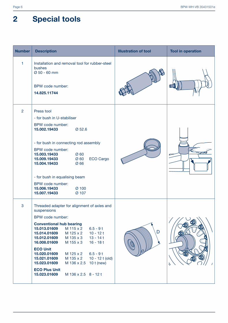
2 Special tools
Number Description Illustration of tool Tool in operation
1 Installation and removal tool for rubber-steel bushesØ 50 - 60 mm
BPW code number:
14.825.11744
2 Press tool
- for bush in U-stabiliser
BPW code number:15.002.19433 Ø 52.6
- for bush in connecting rod assembly
BPW code number:15.003.19433 Ø 6015.009.19433 Ø 60 ECO Cargo15.004.19433 Ø 66
- for bush in equalising beam
BPW code number:15.006.19433 Ø 10015.007.19433 Ø 107
3 Threaded adapter for alignment of axles and suspensions
BPW code number:
Conventional hub bearing
15.013.01609 M 115 x 2 6.5 - 9 t15.014.01609 M 125 x 2 10 - 12 t15.012.01609 M 135 x 3 13 - 14 t16.008.01609 M 155 x 3 16 - 18 t
ECO Unit
15.020.01609 M 125 x 2 6.5 - 9 t15.021.01609 M 135 x 2 10 - 12 t (old)15.023.01609 M 136 x 2.5 10 t (new)
ECO Plus Unit
15.023.01609 M 136 x 2.5 8 - 12 t
BPW-WH-VB 35431501e Page 7
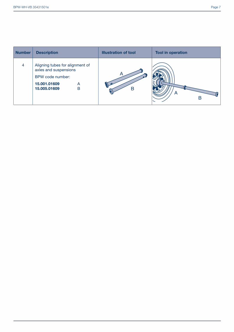
Number Description Illustration of tool Tool in operation
4 Aligning tubes for alignment of axles and suspensions
BPW code number:
15.001.01609 A15.005.01609 B

BPW-WH-VB 35431501ePage 8
�

BPW-WH-VB 35431501e Page 9
�
Equalising beam assembly
ECO Cargo VB...EC
Front
hanger bracket
Rear
hanger bracket
BPW-WH-VB 35431501ePage 10
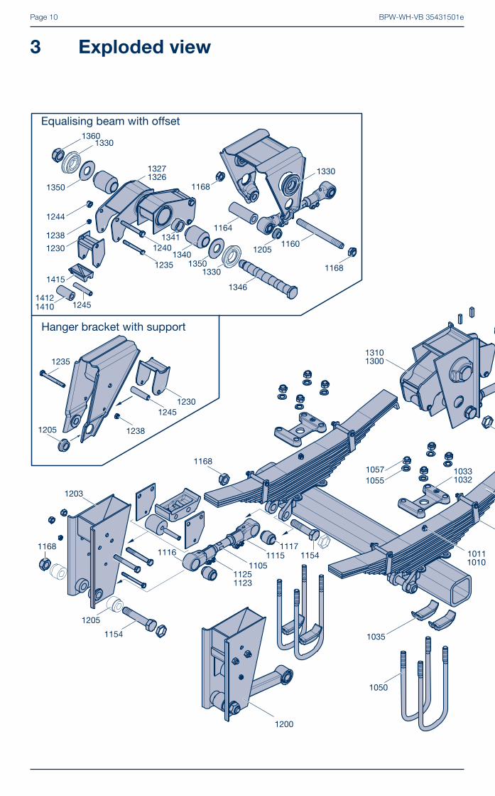
3 Exploded view

BPW-WH-VB 35431501e Page 11

BPW-WH-VB 35431501ePage 12
Pos. Name
1000 Leaf spring1010 Spring screw1011 Hexagon nut1012 Spring clamp1014 Hexagon screw1015 Hexagon nut1016 Tube1028 Support VB1032 Spring plate1033 Spring plate1035 Segment1050 Spring U-bolt1055 Disc1057 Lock nut1167 Shaped part
1200 Front hanger bracket1203 Front hanger bracket1100 Connecting rod, rigid1105 Connecting rod, adjustable1115 Tensioner head, left threaded1116 Tensioner head, right threaded1117 Bush1123 Hexagon screw1125 Lock nut1154 Hexagon screw1155 Hexagon screw1161 Plate (adjusting plate execution VB...EC)1165 Disc (execution VB...EC) 1167 Anti-rotation device for bolts (execution VB...EC)1168 Lock nut1205 Bush1230 Support (slider)1232 Plate1235 Hexagon screw 1238 Lock nut1240 Hexagon screw1244 Lock nut1245 Tube1410 Bush (Silent block bush)1412 Bush1415 Slider
Name
Pos. Name
1300 Equalising beam assembly 1305 Equalising beam assembly1310 Equalising beam assembly1315 Equalising beam assembly1100 Connecting rod, rigid 1105 Connecting rod, adjustable 1115 Tensioner head, left threaded 1116 Tensioner head, right threaded 1117 Bush 1123 Hexagon screw 1125 Lock nut 1154 Hexagon screw 1155 Hexagon screw 1160 Screw 1161 Plate (adjusting plate version VB...EC)1164 Tube1165 Disc (execution VB...EC)1167 Anti-rotation device for bolts (execution VB...EC)1168 Lock nut 1205 Bush 1230 Support (slider) 1235 Hexagon screw 1238 Lock nut 1240 Hexagon screw 1244 Lock nut1245 Tube 1320 Equalising beam 1326 Equalising beam 1327 Equalising beam 1330 Bush 1331 Bush 1340 Bush 1341 Ring 1342 Sleeve (execution VB...EC)1345 Thread bolt 1346 Thread bolt 1347 Grease nipple 1350 Ring 1350 Plate (wearing plate)1352 Disc (execution VB...EC)1353 Disc 1360 Lock nut 1360 Castle nut 1361 Split pin 1370 Ring / Shaped plate (version VB...EC)1410 Rubber bush (silent block bush) 1412 Bush 1415 Slider
Pos. Name
1400 Rear hanger bracket 1405 Rear hanger bracket 1230 Block 1230 Support (slider) 1232 Plate 1235 Hexagon screw 1238 Lock nut 1240 Hexagon screw 1244 Lock nut1245 Tube1410 Rubber bush (silent block bush)1412 Bush 1415 Slider
1600 U-stabiliser1032 Spring plate1033 Spring plate 1156 Hexagon screw1168 Lock nut1347 Grease nipple1637 Lock nut 1641 Bush1642 Shaped plate 1645 Hexagon screw1815 U-bolt1817 Bush1820 Support
BPW-WH-VB 35431501e Page 13
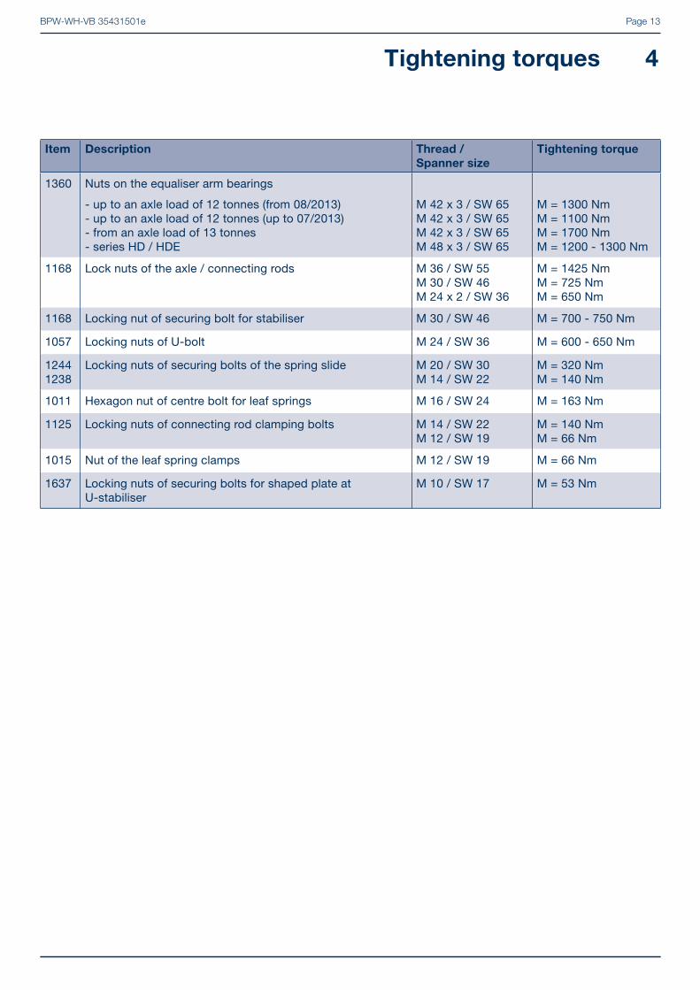
Item Description Thread /
Spanner size
Tightening torque
1360 Nuts on the equaliser arm bearings
- up to an axle load of 12 tonnes (from 08/2013)- up to an axle load of 12 tonnes (up to 07/2013)- from an axle load of 13 tonnes- series HD / HDE
M 42 x 3 / SW 65M 42 x 3 / SW 65M 42 x 3 / SW 65M 48 x 3 / SW 65
M = 1300 NmM = 1100 NmM = 1700 NmM = 1200 - 1300 Nm
1168 Lock nuts of the axle / connecting rods M 36 / SW 55 M 30 / SW 46M 24 x 2 / SW 36
M = 1425 Nm M = 725 NmM = 650 Nm
1168 Locking nut of securing bolt for stabiliser M 30 / SW 46 M = 700 - 750 Nm
1057 Locking nuts of U-bolt M 24 / SW 36 M = 600 - 650 Nm
12441238
Locking nuts of securing bolts of the spring slide M 20 / SW 30M 14 / SW 22
M = 320 NmM = 140 Nm
1011 Hexagon nut of centre bolt for leaf springs M 16 / SW 24 M = 163 Nm
1125 Locking nuts of connecting rod clamping bolts M 14 / SW 22M 12 / SW 19
M = 140 NmM = 66 Nm
1015 Nut of the leaf spring clamps M 12 / SW 19 M = 66 Nm
1637 Locking nuts of securing bolts for shaped plate at U-stabiliser
M 10 / SW 17 M = 53 Nm
Tightening torques 4
BPW-WH-VB 35431501ePage 14
5.1 Safety regulations
• All work must be performed by trained mechanics at competent repair facilities or authorised specialist companies who have access to all relevant tools and have acquired the knowledge required for this work. Anyone who performs maintenance and repair work must be trained in automotive mechanics and already have experience in repairing trailers. Anyone who performs brake work must be trained in brake systems.
• Comply with local safety regulations.
• The relevant operation and service regulations as well as safety regulations of the vehicle manufacturer and of the manufacturers of other vehicle parts must be adhered to.
• The vehicle must be prevented from moving during repair work. Please observe the relevant safety regulations for repair work on commercial vehicles, in particular the safety regulations for jacking up and securing the vehicle.
• During repair work, make sure that the brake is not operated inadvertently. The brake must not be applied.
• Do not perform repair work unless wearing protective clothing (gloves, safety boots, safety goggles, etc.).
• Only use recommended tools.
• A second mechanic must provide assistance when working with heavy components (steering pivots, brake discs, brake drums or brake removal/installation).
• All air lines and components must be depressurised before being removed.
• Following each repair, perform a function check or a test drive in order to make sure that the brakes and suspensions are functioning correctly. New brake linings only have maximum eff ect after a few braking actions. Avoid hard braking.
• All exchanged components must be reused or disposed of in accordance with the applicable environmental regulations, laws and directives.
• The remaining thickness of the brake lining and the condition of the brake disc or brake drum must be visually inspected at regular intervals depending on the way in which the vehicle is used (see BPW maintenance instructions).
• Tighten all fi xings to the recommended tightening torque.
5 Safety regulations, safety information
BPW-WH-VB 35431501e Page 15
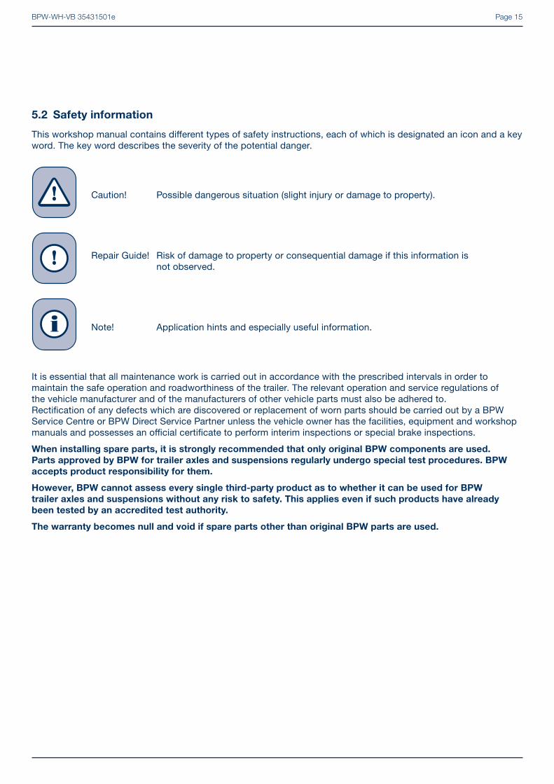
5.2 Safety information
This workshop manual contains diff erent types of safety instructions, each of which is designated an icon and a key word. The key word describes the severity of the potential danger.
Caution! Possible dangerous situation (slight injury or damage to property).
Repair Guide! Risk of damage to property or consequential damage if this information is not observed.
Note! Application hints and especially useful information.
It is essential that all maintenance work is carried out in accordance with the prescribed intervals in order to maintain the safe operation and roadworthiness of the trailer. The relevant operation and service regulations of the vehicle manufacturer and of the manufacturers of other vehicle parts must also be adhered to.Rectifi cation of any defects which are discovered or replacement of worn parts should be carried out by a BPW Service Centre or BPW Direct Service Partner unless the vehicle owner has the facilities, equipment and workshop manuals and possesses an offi cial certifi cate to perform interim inspections or special brake inspections.
When installing spare parts, it is strongly recommended that only original BPW components are used.
Parts approved by BPW for trailer axles and suspensions regularly undergo special test procedures. BPW
accepts product responsibility for them.
However, BPW cannot assess every single third-party product as to whether it can be used for BPW
trailer axles and suspensions without any risk to safety. This applies even if such products have already
been tested by an accredited test authority.
The warranty becomes null and void if spare parts other than original BPW parts are used.
i
BPW-WH-VB 35431501ePage 16
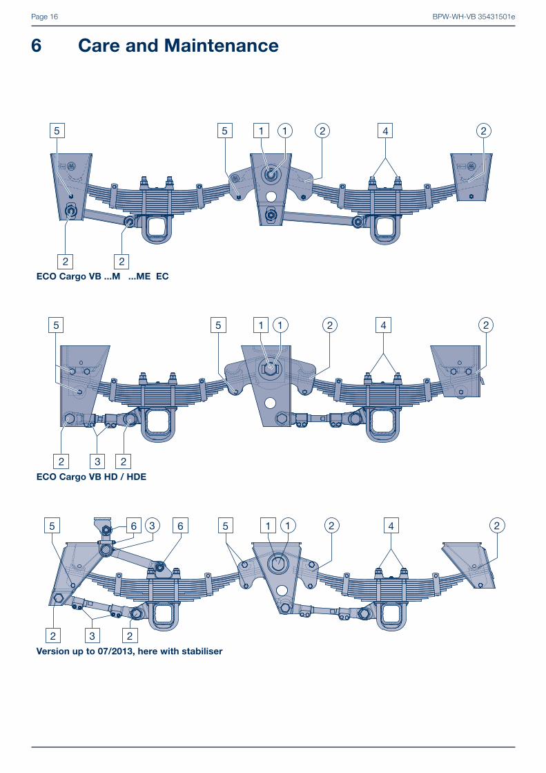
6 Care and Maintenance
ECO Cargo VB ...M ...ME EC
ECO Cargo VB HD / HDE
Version up to 07/2013, here with stabiliser

BPW-WH-VB 35431501e Page 17
Lubrication and maintenance work
Overview
Lubricate
Maintenance work
For detailed description see pages 18 and 21 initi
ally
ever
y 6
wee
ks
twic
e an
nual
ly 1
)
annu
ally
1)
1 Grease equalising beam bearings (suspension type E) with special longlife grease ECO-LiPlus. (Not applicable in the case of rubber-steel bushes)
1 1
2 Lightly grease the slide elements/slide ends of springs. 2 2
3 Grease stabiliser bearing bushes with BPW special longlife grease ECO-LiPlus and check for wear.
3 3
1 Check threaded bolts on equaliser beam bearings for fi rm seating.
up to an axle load of 12 tonnes (from 08/2013) M 42 x 3 / SW 65 M = 1300 Nm up to an axle load of 12 tonnes (up to 07/2013) M 42 x 3 / SW 65 M = 1100 Nm from an axle load of 13 tonnes M 42 x 3 / SW 65 M = 1700 Nm Series HD / HDE M 48 x 3 / SW 65 M = 1200 - 1300 Nm
1
2 Check axle connecting rod bolts for fi rm seating using a torque wrench.
M 24 x 2 / SW 36 M = 650 Nm M 30 / SW 46 M = 725 Nm M 36 / SW 55 M = 1425 Nm
2 2
3 Check connecting rod clamping bolts for fi rm seating.
M 12 / SW 19 M = 66 Nm M 14 / SW 22 M = 140 Nm
3
4 Check spring U-bolts for fi rm seating using a torque wrench
M 24 / SW 36 M = 600 - 650 Nm4 4
5 Check slide elements for fi rm seating.
M 14 / SW 22 M = 140 Nm M 20 / SW 30 M = 320 Nm
5
- Visual inspection. Check all component parts and welding seams for wear and damage.
-
6 Check the stabiliser attachments.
M 10 / SW 17 M = 53 Nm M 30 / SW 46 M = 700 - 750 Nm
6
1) Under extreme conditions, with more frequency.
Note: Components that have damage due to improper mounting are to be replaced after a review by a BPW Service Centre.
BPW-WH-VB 35431501ePage 18
6 Care and Maintenance
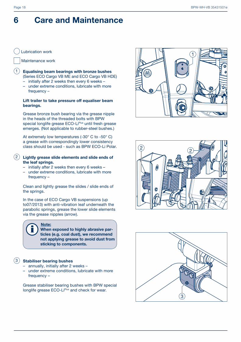
3 Stabiliser bearing bushes
– annually, initially after 2 weeks –– under extreme conditions, lubricate with more frequency –
Grease stabiliser bearing bushes with BPW special longlife grease ECO-LiPlus and check for wear.
2 Lightly grease slide elements and slide ends of the leaf springs.– initially after 2 weeks then every 6 weeks –– under extreme conditions, lubricate with more frequency –
Clean and lightly grease the slides / slide ends of the springs.
In the case of ECO Cargo VB suspensions (up to07/2013) with anti-vibration leaf underneath the parabolic springs, grease the lower slide elements via the grease nipples (arrow).
Note:
When exposed to highly abrasive par-
ticles (e.g. coal dust), we recommend
not applying grease to avoid dust from
sticking to components.
Lubrication work
Maintenance work
1 Equalising beam bearings with bronze bushes (Series ECO Cargo VB ME and ECO Cargo VB HDE)– initially after 2 weeks then every 6 weeks –– under extreme conditions, lubricate with more frequency –
Lift trailer to take pressure off equaliser beam
bearings.
Grease bronze bush bearing via the grease nipple in the heads of the threaded bolts with BPW special longlife grease ECO-LiPlus until fresh grease emerges. (Not applicable to rubber-steel bushes.)
At extremely low temperatures (-30° C to -50° C) a grease with correspondingly lower consistency class should be used - such as BPW ECO-Li Polar.

BPW-WH-VB 35431501e Page 19
1 Equaliser beam bearings
– twice annually –
Check nuts on the equaliser beam bearings for fi rm seating. The service life of the rubber-steel bush bearings is dependent on the fi rm seating of the inner steel bush.
Tightening torques: up to an axle load of 12 tonnes (from 08/2013) M 42 x 3 (SW 65) M = 1300 Nm
up to an axle load of 12 tonnes (up to 07/2013) M 42 x 3 (SW 65) M = 1100 Nm
from an axle load of 13 tonnes M 42 x 3 (SW 65) M = 1700 Nm
Series HD / HDE M 48 x 3 (SW 65) M = 1200 - 1300 Nm
2 Axle connecting rods
– twice annually, initially after 2 weeks –
Check lock nuts of the axle guide linkages / connecting rods for fi rm seating using a torque wrench.
Tightening torques: M 24 x 2 (SW 36) M = 650 Nm M 30 (SW 46) M = 725 Nm M 36 (SW 65) M = 1425 Nm
3 Connecting rods (only for series VB up to manu-facturing year 08.2013 and ECO Cargo VB HD)– twice annually –
Check connecting rod clamping screws for tightness.
Tightening torques: M 12 (SW 19) M = 66 Nm M 14 (SW 22) M = 140 Nm

BPW-WH-VB 35431501ePage 20
6 Care and Maintenance
4 Spring U-bolts
– twice annually, initially after 2 weeks –
Check spring U-bolts for tightness. If necessary loosen lock nuts, tighten nuts alternately to the prescribed torque, and a bit at a time, if necessary then re-lock.
Tightening torque: M 24 (SW 36) M = 600 - 650 Nm
5 Slide elements
– twice annually –
Check slide elements and lateral wear plates in the shackle and equaliser beam for wear and the fastening screws for fi rm seating.
Tightening torques: M 14 (SW 22) M = 140 Nm M 20 (SW 30) M = 320 Nm
If necessary, check rubber rollers under the spring ends for wear.
BPW-WH-VB 35431501e Page 21
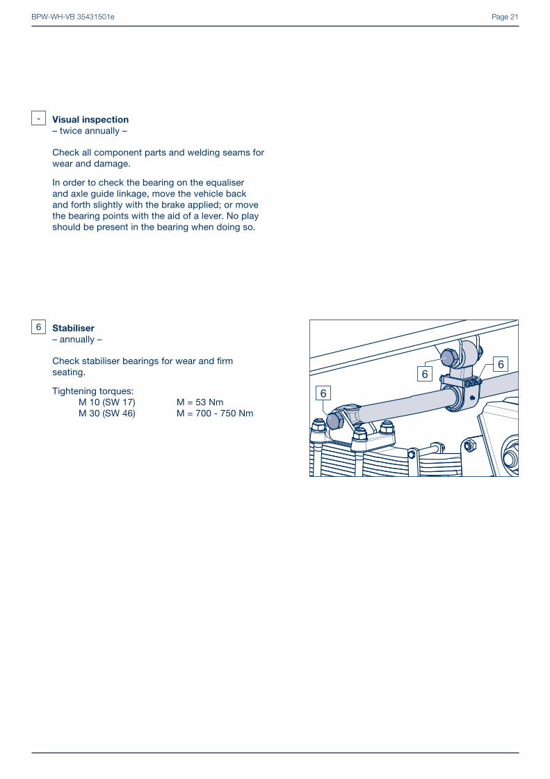
- Visual inspection
– twice annually –
Check all component parts and welding seams for wear and damage.
In order to check the bearing on the equaliser and axle guide linkage, move the vehicle back and forth slightly with the brake applied; or move the bearing points with the aid of a lever. No play should be present in the bearing when doing so.
6 Stabiliser
– annually –
Check stabiliser bearings for wear and fi rm seating.
Tightening torques: M 10 (SW 17) M = 53 Nm M 30 (SW 46) M = 700 - 750 Nm

BPW-WH-VB 35431501ePage 22
[7] If axles with U-stabiliser (1815) are fi tted, the secu-ring bolts (1156) at the spring plates (1032, 1033) must be removed.
7.1 Removing
[1] Safely support the vehicle frame.
[2] Slightly raise axle with vehicle lift and support in secure position. Dismantle wheels.
[3] Deactivate brakes. Dismantle air brake pipes for brake cylinder or air brake chamber (steering axle) and tension cable for parking brake.
[4] Unscrew locking nuts (1168, SW 36 / SW 46 / SW 55) from the securing bolts (1154) of the left and right connecting rod (1100, 1105).
7 Removing and installing axle with leaf springs
Picture 1
Picture 2
Picture 3
1168
10331032
1156
1815
[5] In the ECO Cargo version with track adjustment on the hanger bracket, remove the washers (1165) and the link discs (1161) from the bolts (1154).
Repair guide!
When the link discs are tacked on, the
tack-weld points must be removed if
necessary.
[6] In ECO Cargo with link discs, remove the bolts (1154), from the hanger brackets and tie rods (1100, 1105).

BPW-WH-VB 35431501e Page 23
- Multi-leaf spring /
parabolic spring without anti-vibration leaf:
[8] Unscrew lock nuts (1238, SW 22) from the fi xing bolts (1235) on the equalising beam (1320, 1326, 1327) or the hanger bracket.
[9] Take out the securing bolts (1235).
[10] Take the tube (1245) with bush, if necessary (1410, 1412) out of both sides of the equaliser or support.
� Continue with work step [11].
Picture 4
Picture 5
Picture 6
- Parabolic spring with anti-vibration leaf:
[8] Clamp the spring parts of the leaf spring (1000) together.
[9] Unscrew lock nuts (1238, SW 22) and remove the fi xing bolts (1235) from the equalising beam and or the hanger bracket.
[10] Take out slider (1415) with tube (1245).
1235
1415
1238
1000
1245
[11] Lower the axle and pull out.
Caution! RISK OF INJURY
Protect the axle from falling off the
jack. When lowering, leave suffi cient
room under the vehicle.
[12] Check bushes (1117) in the connecting rods (1100, 1105) for wear, if necessary remove connecting rod and change bushes.
� See Chapter 7.3 on page 27 for installation.

BPW-WH-VB 35431501ePage 24
7 Removing and installing axle with leaf springs
Picture 7
Picture 8
Picture 9
7.2 Replacing the bushes in the connecting
rods
- Connecting rods version VB...EC:
Note:
ECO Cargo version connecting rods
must be removed and the bushes
pressed out or in.
[13] Align connecting rod (1100, 1105) under a press.
[14] Press bush (1117) with a stepped bolt, Ø approx. 22/45 mm, from the connecting rod.
[15] Align eye of the connecting rod (1100, 1105) in the centre on a backing with a hole diameter of approximately 66 mm.
[16] Insert push-in tool (BPW No. 15.009.19433) with the phase (arrow) in the connecting rod eye.
[17] Coat rubber-steel bush (1117) with soapy water or tyre fi tting paste and insert it into the tool.
[18] Push the bush in with the stepped bolt until the push-in tool releases.

BPW-WH-VB 35431501e Page 25
Picture 10
Picture 11
Picture 12
[21] Press in bush (1117) with appropriate pressure sleeve until the projecting end is the same on both sides (picture 12/arrows).
� Continue with work step [29].
1117
11001105
1117
11051100
- All other suspension types:
Note:
The pressing in or out can be carried
out under a press or with a drawing
tool.
Push in under a press
[20] When pushing in under a press, coat the rubber-steel bush (1117) with soapy water and insert into the assembly tool.
BPW No.: Ø 60 15.003.19433 Ø 66 15.004.19433
[19] Remove push-in tool and stepped bolt. Rotate connecting rod and, if necessary, push the bush (1117) in a little in the opposite direction.
Repair guide!
The projection on both sides must be
the same
� Continue with work step [29].
BPW-WH-VB 35431501ePage 26
7 Removing and installing axle with leaf springs
Picture 13
Picture 14
Picture 15
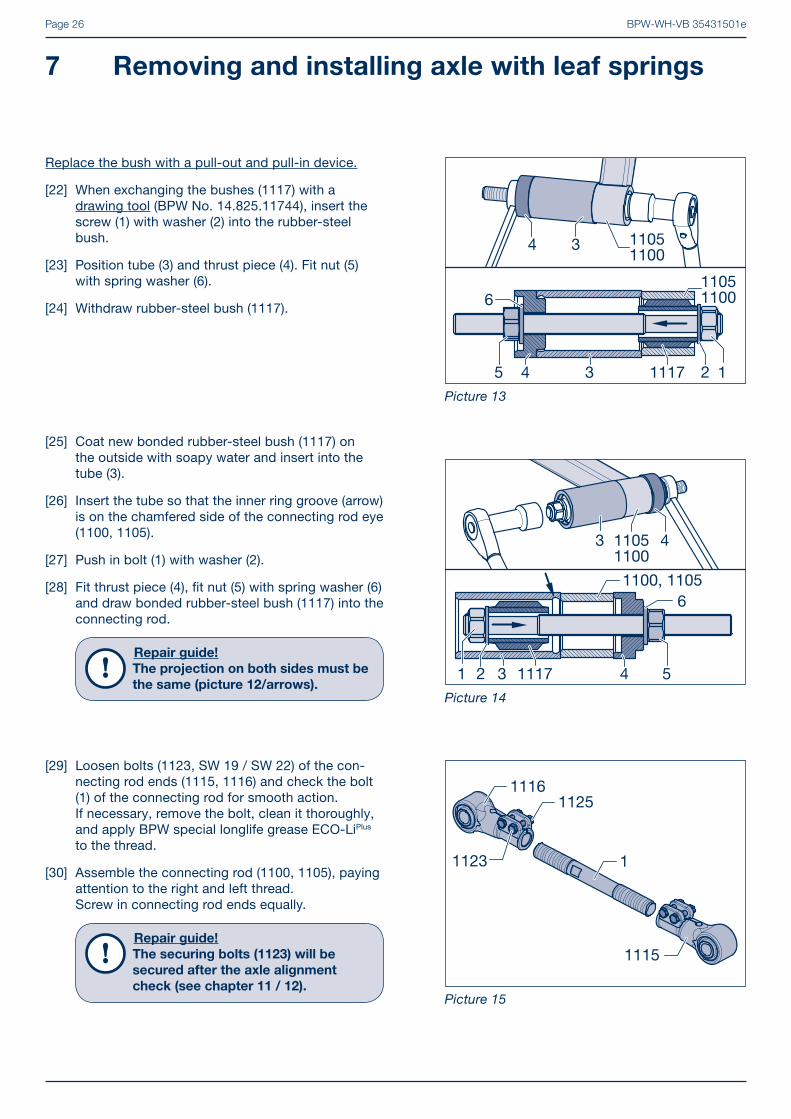
[29] Loosen bolts (1123, SW 19 / SW 22) of the con-necting rod ends (1115, 1116) and check the bolt (1) of the connecting rod for smooth action. If necessary, remove the bolt, clean it thoroughly, and apply BPW special longlife grease ECO-LiPlus to the thread.
[30] Assemble the connecting rod (1100, 1105), paying attention to the right and left thread.Screw in connecting rod ends equally.
Repair guide!
The securing bolts (1123) will be
secured after the axle alignment
check (see chapter 11 / 12).
1116
1
1125
1123
1115
Replace the bush with a pull-out and pull-in device.
[22] When exchanging the bushes (1117) with a drawing tool (BPW No. 14.825.11744), insert the screw (1) with washer (2) into the rubber-steel bush.
[23] Position tube (3) and thrust piece (4). Fit nut (5) with spring washer (6).
[24] Withdraw rubber-steel bush (1117).
13
34
45
6
1117
11051100
11051100
2
[25] Coat new bonded rubber-steel bush (1117) on the outside with soapy water and insert into the tube (3).
[26] Insert the tube so that the inner ring groove (arrow) is on the chamfered side of the connecting rod eye (1100, 1105).
[27] Push in bolt (1) with washer (2).
[28] Fit thrust piece (4), fi t nut (5) with spring washer (6) and draw bonded rubber-steel bush (1117) into the connecting rod.
Repair guide!
The projection on both sides must be
the same (picture 12/arrows).1 3
43
4 5
6
1117
1100, 1105
11051100
2

BPW-WH-VB 35431501e Page 27
Picture 16
Picture 17
Picture 18
7.3 Installing
[31] Check the support plate (1230) in the equalising beam and the slippers in the hanger bracket for wear, see chapter 10.
[32] Place axle securely on vehicle lift, push under vehicle and raise. Align axle with leaf springs and insert into the equalising beam or support.
- Multi-leaf spring / parabolic spring without
antivibration leaf:
[33] Check tube (1245) if necessary with bush (1410, 1412) for wear, use new one as appropriate and insert into the equalising beam or support. Insert securing bolt (1235).
[34] Fit new locking nuts (1238) and tighten to the specifi ed torque.
Tightening torques: M 14 (SW 22) M = 140 Nm M 20 (SW 30) M = 320 Nm
� Continue with work step [37] on page 28.
- Parabolic spring with anti-vibration leaf:
[33] Check the slipper (1415) and replace, if necessary. Press in the greased tube (1245).
1415 1245
[34] Clamp the spring parts together.
[35] Insert slider (1415) with securing bolt (1235), grease nipple (arrow) pointing to axle.
[36] Fit new locking nut (1238) and tighten to the specifi ed torque.
Tightening torques: M 14 (SW 22) M = 140 Nm M 20 (SW 30) M = 320 Nm
1235
1415
1238
1000
1245
BPW-WH-VB 35431501ePage 28
7 Removing and installing axle with leaf springs
Picture 19
Picture 20
Picture 21
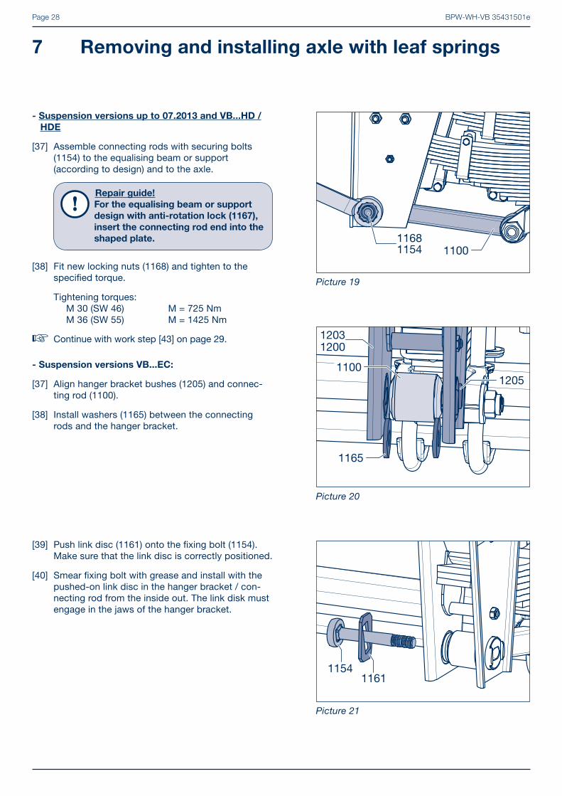
[39] Push link disc (1161) onto the fi xing bolt (1154). Make sure that the link disc is correctly positioned.
[40] Smear fi xing bolt with grease and install with the pushed-on link disc in the hanger bracket / con-necting rod from the inside out. The link disk must engage in the jaws of the hanger bracket.
- Suspension versions VB...EC:
[37] Align hanger bracket bushes (1205) and connec-ting rod (1100).
[38] Install washers (1165) between the connecting rods and the hanger bracket.
- Suspension versions up to 07.2013 and VB...HD /
HDE
[37] Assemble connecting rods with securing bolts (1154) to the equalising beam or support (according to design) and to the axle.
Repair guide!
For the equalising beam or support
design with anti-rotation lock (1167),
insert the connecting rod end into the
shaped plate.
[38] Fit new locking nuts (1168) and tighten to the specifi ed torque.
Tightening torques: M 30 (SW 46) M = 725 Nm M 36 (SW 55) M = 1425 Nm
� Continue with work step [43] on page 29.

BPW-WH-VB 35431501e Page 29
[42] On both sides, align the centre link discs (1161) and lock nuts (1168, SW 36) slightly tighten - do not tighten.(The bolts are tightened when the axle tracking has been adjusted).
[41] Install link disc (1161), washer (1165) and new lock nut (1168). The bevels of the link discs must be aligned to each other and engage on both sides in the jaws of the hanger bracket.
Repair guide!
Do not tighten lock nuts!
Picture 22
[43] Attach air brake pipes to brake cylinder or air brake chamber (steering axle) and cable for parking brake.
[44] Fit wheels.
[45] Lubricate slider (1415, arrow) on axles with anti-vibration leaf with BPW special long-term grease ECO-LiPlus, until fresh grease emerges.
Repair guide!
After removing the axle or exchanging
suspension parts, an axle alignment
check must be carried out (see
chapter 11 / 12).
Picture 24
1415
Picture 23
BPW-WH-VB 35431501ePage 30
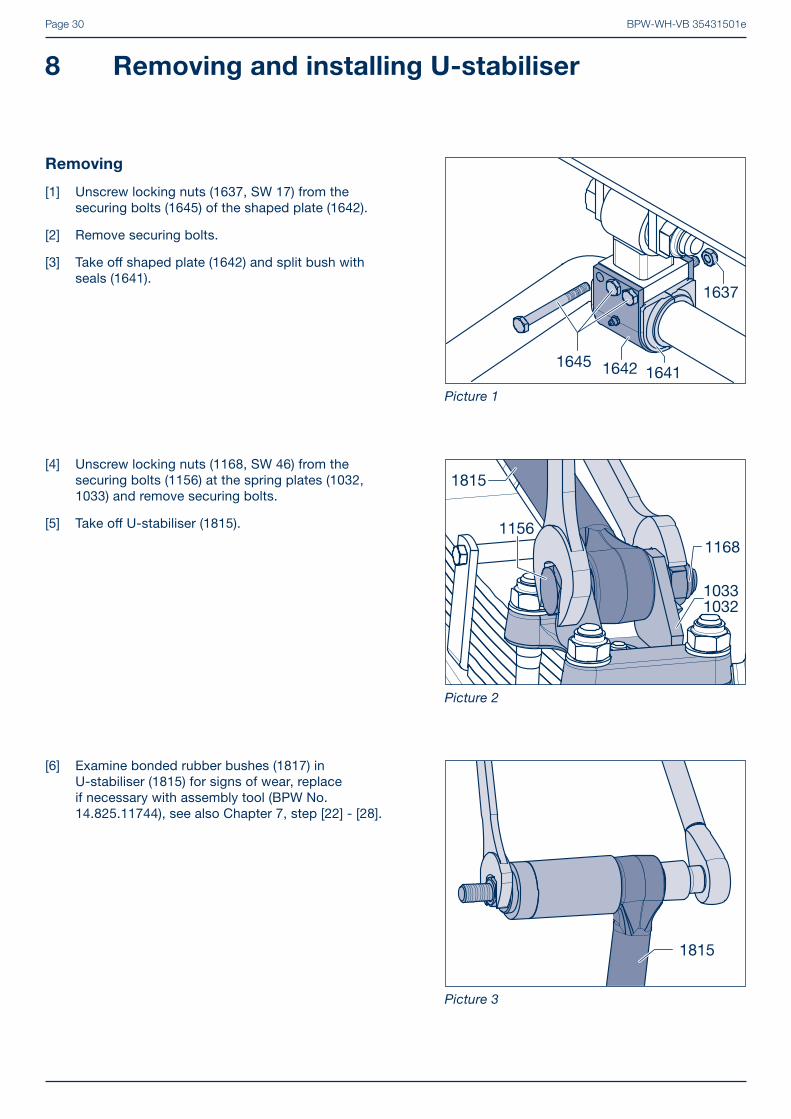
[6] Examine bonded rubber bushes (1817) in U-stabiliser (1815) for signs of wear, replace if necessary with assembly tool (BPW No. 14.825.11744), see also Chapter 7, step [22] - [28].
[4] Unscrew locking nuts (1168, SW 46) from the securing bolts (1156) at the spring plates (1032, 1033) and remove securing bolts.
[5] Take off U-stabiliser (1815).
Removing
[1] Unscrew locking nuts (1637, SW 17) from the securing bolts (1645) of the shaped plate (1642).
[2] Remove securing bolts.
[3] Take off shaped plate (1642) and split bush with seals (1641).
8 Removing and installing U-stabiliser
Picture 1
Picture 2
Picture 3
1637
1645 1642 1641
1168
10331032
1156
1815
1815
BPW-WH-VB 35431501e Page 31
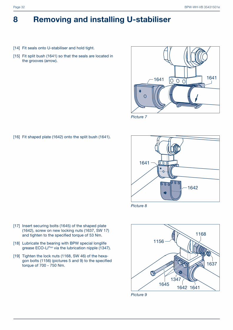
[12] Examine split bush (1641) and seals for sign of wear, fi t new parts if necessary.
[13] Smear split bush with BPW special longlife grease ECO-LiPlus.
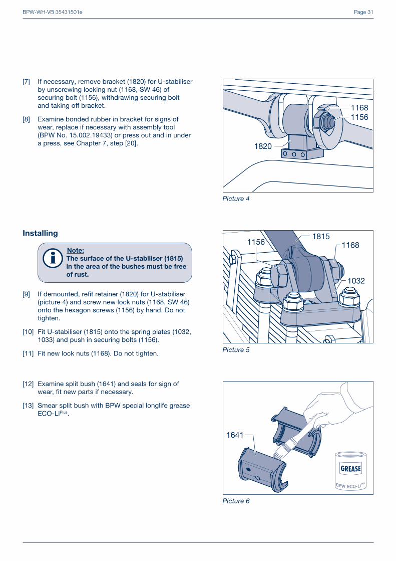
Installing
Note:
The surface of the U-stabiliser (1815)
in the area of the bushes must be free
of rust.
[9] If demounted, refi t retainer (1820) for U-stabiliser (picture 4) and screw new lock nuts (1168, SW 46) onto the hexagon screws (1156) by hand. Do not tighten.
[10] Fit U-stabiliser (1815) onto the spring plates (1032, 1033) and push in securing bolts (1156).
[11] Fit new lock nuts (1168). Do not tighten.
[7] If necessary, remove bracket (1820) for U-stabiliser by unscrewing locking nut (1168, SW 46) of securing bolt (1156), withdrawing securing bolt and taking off bracket.
[8] Examine bonded rubber in bracket for signs of wear, replace if necessary with assembly tool (BPW No. 15.002.19433) or press out and in under a press, see Chapter 7, step [20].
Picture 4
Picture 5
Picture 6
1820
11561168
116811561815
1032
1641
BPW-WH-VB 35431501ePage 32
[17] Insert securing bolts (1645) of the shaped plate (1642), screw on new locking nuts (1637, SW 17) and tighten to the specifi ed torque of 53 Nm.
[18] Lubricate the bearing with BPW special longlife grease ECO-LiPlus via the lubrication nipple (1347).
[19] Tighten the lock nuts (1168, SW 46) of the hexa-gon bolts (1156) (pictures 5 and 9) to the specifi ed torque of 700 - 750 Nm.
[16] Fit shaped plate (1642) onto the split bush (1641).
[14] Fit seals onto U-stabiliser and hold tight.
[15] Fit split bush (1641) so that the seals are located in the grooves (arrow).
8 Removing and installing U-stabiliser
Picture 7
Picture 8
Picture 9
1641 1641
1642
1641
1637
1156
1168
16451642
1347
1641

BPW-WH-VB 35431501e Page 33
[9] Place spring clamps (1012) over the spring leaves and insert distance sleeve (1016).
[10] Insert hexagonal screws (1014). Fit nuts (1015), tighten with the prescribed torque of 66 Nm and secure with a counter-nuts.
[4] Take apart corroded leaf springs (1000). Unscrew hexagon nut (1011, SW 24) and remove spring screw (1010).
[5] Unscrew nuts (1015, SW 19) from hexagon bolts (1014) and remove spring clips (1012).
[6] Thoroughly clean each leaf with a wire bush and inspect it for cracks.Replace heavily corroded spring leaves and those having cracks. Change the top spring leaf when the wear is more than 20% of the leaf thickness.
[7] Apply graphite grease to the cleaned spring leaves.
[8] Insert centre bolt and tighten nut with the prescribed torque of 163 Nm.
Removing
[1] Remove axle with leaf spring, see chapter 7 work procedures 1-12.
[2] Unscrew the double nuts or the self-locking nuts (1057, SW 36) from the U-bolts. Remove the washers (1055). Remove spring plates (1032, 1033) and remove the spring U-bolt (1050).
[3] Remove leaf spring (1000) from the axle.
Note:
Parabolic and multi-leaf springs can be
installed.
Removing and installing leaf springs 9
Picture 1
Picture 2
Picture 3
10571055
1000
10331032
1050
1000
10111010
BPW-WH-VB 35431501ePage 34
9 Removing and installing leaf springs
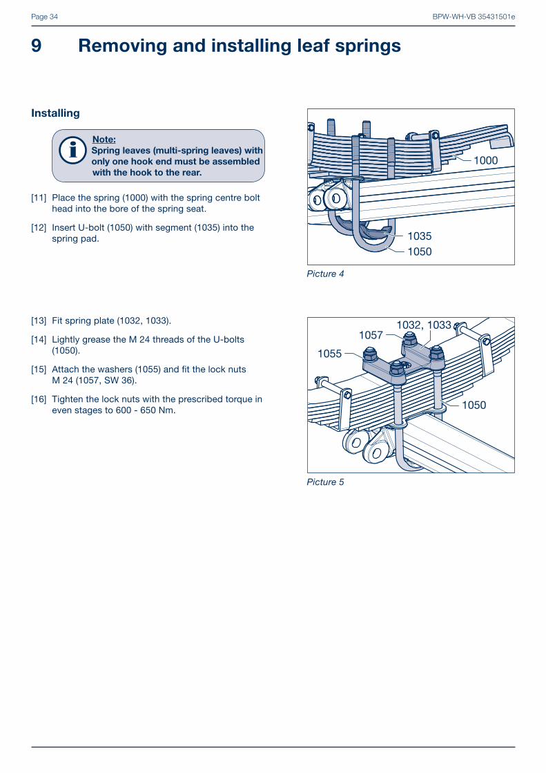
[13] Fit spring plate (1032, 1033).
[14] Lightly grease the M 24 threads of the U-bolts (1050).
[15] Attach the washers (1055) and fi t the lock nuts M 24 (1057, SW 36).
[16] Tighten the lock nuts with the prescribed torque in even stages to 600 - 650 Nm.
Installing
Note:
Spring leaves (multi-spring leaves) with
only one hook end must be assembled
with the hook to the rear.
[11] Place the spring (1000) with the spring centre bolt head into the bore of the spring seat.
[12] Insert U-bolt (1050) with segment (1035) into the spring pad.
Picture 4
Picture 5
1000
10501035
1050
10571032, 1033
1055
BPW-WH-VB 35431501e Page 35
Removing and installing equalising beam 10
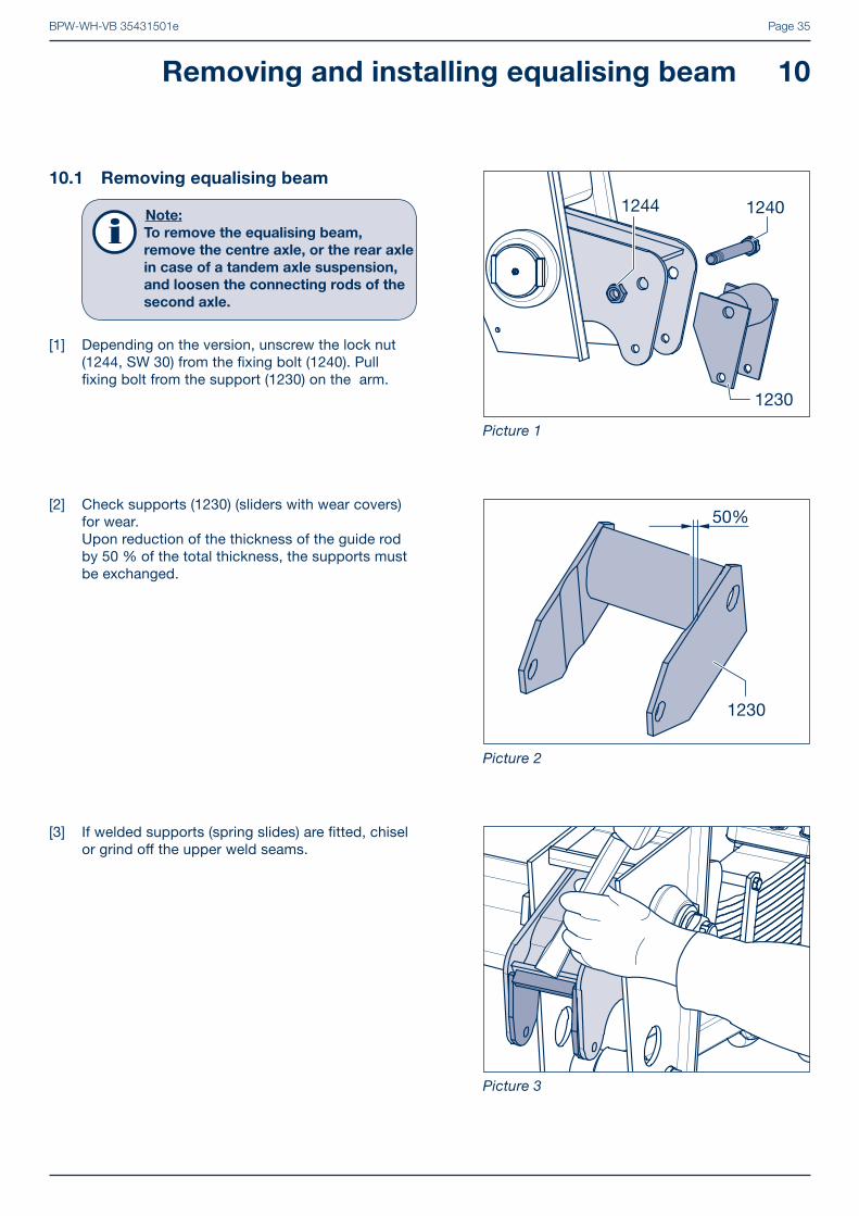
[3] If welded supports (spring slides) are fi tted, chisel or grind off the upper weld seams.
[2] Check supports (1230) (sliders with wear covers) for wear. Upon reduction of the thickness of the guide rod by 50 % of the total thickness, the supports must be exchanged.
10.1 Removing equalising beam
Note:
To remove the equalising beam,
remove the centre axle, or the rear axle
in case of a tandem axle suspension,
and loosen the connecting rods of the
second axle.
[1] Depending on the version, unscrew the lock nut (1244, SW 30) from the fi xing bolt (1240). Pull fi xing bolt from the support (1230) on the arm.
Picture 1
Picture 2
Picture 3
BPW-WH-VB 35431501ePage 36
10 Removing and installing equalising beam
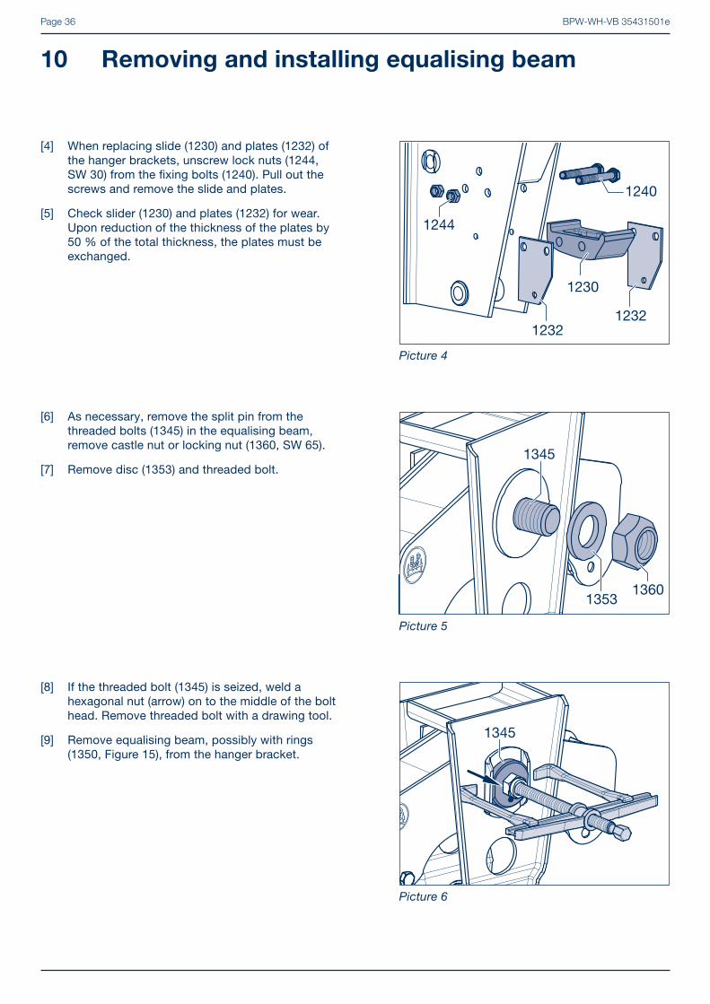
[8] If the threaded bolt (1345) is seized, weld a hexagonal nut (arrow) on to the middle of the bolt head. Remove threaded bolt with a drawing tool.
[9] Remove equalising beam, possibly with rings (1350, Figure 15), from the hanger bracket.
[6] As necessary, remove the split pin from the threaded bolts (1345) in the equalising beam, remove castle nut or locking nut (1360, SW 65).
[7] Remove disc (1353) and threaded bolt.
[4] When replacing slide (1230) and plates (1232) of the hanger brackets, unscrew lock nuts (1244, SW 30) from the fi xing bolts (1240). Pull out the screws and remove the slide and plates.
[5] Check slider (1230) and plates (1232) for wear.Upon reduction of the thickness of the plates by 50 % of the total thickness, the plates must be exchanged.
Picture 4
Picture 5
Picture 6
1232
1230
1244
1240
1232

BPW-WH-VB 35431501e Page 37
Over 13 t axle load:
[11] Place ring (1350) on the equalising beam. Insert new bronze bush (1340) and press in with thrust piece until fl ush on each side.
Repair guide!
Do not push the inner bushes (1340)
against each other! There must be a
space between the two bushes for
grease distribution (see picture 9).
After installation there must be an
excess of 4 mm on both sides.
10.2 Replacing bronze bushes
� See Chapter 10.3 on page 38 for version with rubber bush.
[10] Check bronze bush (1340) in the equalising beam for wear. As necessary, push out under a press.
Up to 12 t axle load:
[11] Insert new bronze bush (1340) and press in with thrust piece until fl ush on each side (also see picture 9).
Picture 7
Picture 8
Picture 9
1340
1340
1350
44
Axle load 12t Axle load 13t

BPW-WH-VB 35431501ePage 38
10 Removing and installing equalising beam
Picture 10
Picture 11
Picture 12
Version VB...ME EC
[12] In version VB...EC, smear the inside and outside of the sleeve (1342) with special BPW long-life grease ECO-LiPlus and insert it into the equalising beam.
� For how to install the qualizing beam, see Chapter 10.4 on page 39.
10.3 Replace the rubber-steel bush
[10] Check rubber-steel bush (1340) in equalising beam for wear. Upon detection of wear, push out under a press.
[11] Coat the outside of the new bushes (1340) with soapy water and press into position using the extraction tool and suitable mandrel. After installation there must be an equal excess of the bush on both sides.
BPW code number of extraction tool: Ø 100 15.006.19433 Ø 107 15.007.19433
1340
[12] For equalising beams with an off set A of 122 mm, press in a rubber-steel bush (1340) from each side until fl ush.
A
1340

BPW-WH-VB 35431501e Page 39
10.4 Install equaliser beam
Suspension versions VB...EC:
[16] Check wear plates (1350) and wear discs (1352) for wear, replace if necessary and weld-tack again.
[17] Insert equaliser beam (1320) into the hanger bracket.
� Continue with work step [18] on page 40.
Picture 13
Picture 14
Picture 15
[13] For equalising beams with an off set A of 160 mm, a spacer sleeve (1341) must be inserted between the rubber-steel bushes (1340).
[14] Insert threaded bolt as guide into the bushes and press in bushes (1340).
[15] To ensure that the bushes are fl ush, they must be pressed in a little further to compensate for relaxation.When the bushes have been pressed into position, they have to be equally fl ush on both sides of the equalising beam.
A
1340
1341
Suspension versions up to 07.2013 and VB...HD / HDE with loose wear rings
[16] Check rings (1350) and weld-in bushes (1205) for wear and replace if necessary. Smear rings on both sides with grease and place on the equaliser beam.
[17] Insert equaliser beam (1320) with rings into the hanger bracket.
� Continue with work step [18] on page 40.

BPW-WH-VB 35431501ePage 40
[19] Smear the disc (1353) with grease and push onto the threaded bolt (1345).
[20] Screw on new lock nut or castle nut (1360, SW 65) and tighten to the specifi ed torque.
Tightening torques: up to 12 t (from 08/2013) M 42 x 3 M = 1300 Nm up to 12 t (up to 07/2013) M 42 x 3 M = 1100 Nm from 13 t M 42 x 3 M = 1700 Nm serie HD / HDE M 48 x 3 M = 1200 - 1300 Nm
[21] If necessary, tighten castle nut up to the next locking option and secure with cotter pin (1361).
10 Removing and installing equalising beam
Picture 16
Picture 17
Picture 18
[18] Grease thread bolt (1345) and insert from outside to inside into the bore hole support / equalising beam. The head of the threaded bolt must be inserted in the anti-rotation device (1370).
� See Chapter 10.4 on page 39 for installation of equalising beam.
Suspension versions up to 07.2013 and VB...HD / HDE with welded wear plates
[16] Check welded wear plates (1350) on the equalising beam and weld-in bushes (1205) in the hanger bracket for wear and replace if necessary. Grease wear plates.
[17] Insert equalising beam (1320) into the hanger bracket.
BPW-WH-VB 35431501e Page 41
Version with bronze bushes
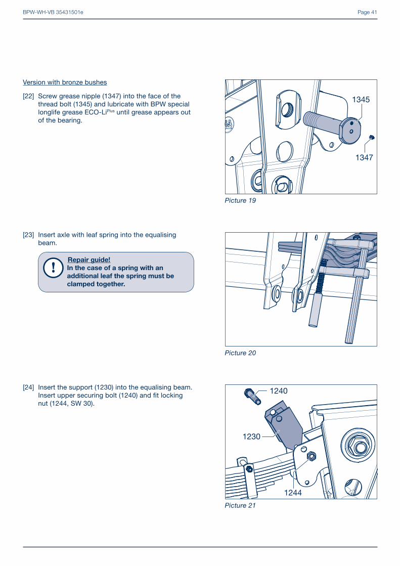
[22] Screw grease nipple (1347) into the face of the thread bolt (1345) and lubricate with BPW special longlife grease ECO-LiPlus until grease appears out of the bearing.
Picture 19
Picture 20
Picture 21
[23] Insert axle with leaf spring into the equalising beam.
Repair guide!
In the case of a spring with an
additional leaf the spring must be
clamped together.
[24] Insert the support (1230) into the equalising beam. Insert upper securing bolt (1240) and fi t locking nut (1244, SW 30).
1240
1230
1244
BPW-WH-VB 35431501ePage 42
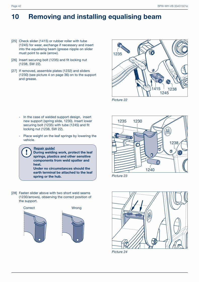
[28] Fasten slider above with two short weld seams (1230/arrows), observing the correct position of the support.
Correct Wrong
- In the case of welded support design, insert new support (spring slide, 1230). Insert lower securing bolt (1235) with tube (1245) and fi t locking nut (1238, SW 22).
- Place weight on the leaf springs by lowering the vehicle.
Repair guide!
During welding work, protect the leaf
springs, plastics and other sensitive
components from weld spatter and
heat.
Under no circumstances should the
earth terminal be attached to the leaf
spring or the hub.
10 Removing and installing equalising beam
Picture 22
Picture 23
Picture 24
[25] Check slider (1415) or rubber roller with tube (1245) for wear, exchange if necessary and insert into the equalising beam (grease nipple on slider must point to axle (arrow).
[26] Insert securing bolt (1235) and fi t locking nut (1238, SW 22).
[27] If removed, assemble plates (1232) and sliders (1230) (see picture 4 on page 36) on to the support and grease.
1235
12381245
1415

BPW-WH-VB 35431501e Page 43
Picture 25
[29] Tighten locking nuts (1238, 1244) to the specifi ed torque.
Tightening torques: M 14 (SW 22) M = 140 Nm M 20 (SW 30) M = 320 Nm
123812441244
1238
[30] Insert connecting rod (1100, 1105) into the hanger bracket.
[31] See page 28, from work step [37] for screw connection of the connecting rod.
Picture 26
BPW-WH-VB 35431501ePage 44
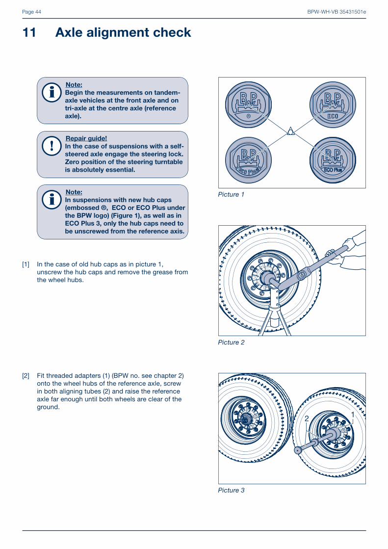
[2] Fit threaded adapters (1) (BPW no. see chapter 2) onto the wheel hubs of the reference axle, screw in both aligning tubes (2) and raise the reference axle far enough until both wheels are clear of the ground.
[1] In the case of old hub caps as in picture 1, unscrew the hub caps and remove the grease from the wheel hubs.
Note:
Begin the measurements on tandem-
axle vehicles at the front axle and on
tri-axle at the centre axle (reference
axle).
Repair guide!
In the case of suspensions with a self-
steered axle engage the steering lock.
Zero position of the steering turntable
is absolutely essential.
Note:
In suspensions with new hub caps
(embossed ®, ECO or ECO Plus under
the BPW logo) (Figure 1), as well as in
ECO Plus 3, only the hub caps need to
be unscrewed from the reference axis.
Picture 1
Picture 2
Picture 3
11 Axle alignment check
R
2 1
BPW-WH-VB 35431501e Page 45
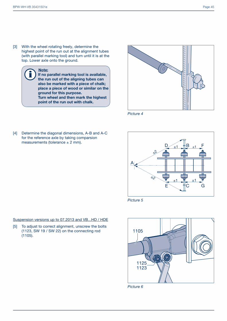
[4] Determine the diagonal dimensions, A-B and A-C for the reference axle by taking comparsion measurements (tolerance ± 2 mm).
[3] With the wheel rotating freely, determine the highest point of the run out at the alignment tubes (with parallel marking tool) and turn until it is at the top. Lower axle onto the ground.
Note:
If no parallel marking tool is available,
the run out of the aligning tubes can
also be marked with a piece of chalk;
place a piece of wood or similar on the
ground for this purpose.
Turn wheel and then mark the highest
point of the run out with chalk.
Picture 4
Picture 5
Picture 6
FBD
GCE
A
±2
±2
±1 ±1
±1 ±1
Suspension versions up to 07.2013 and VB...HD / HDE
[5] To adjust to correct alignment, unscrew the bolts (1123, SW 19 / SW 22) on the connecting rod (1105).
BPW-WH-VB 35431501ePage 46
11 Axle alignment check
[6] Turn the adjustable connecting rod (SW 36) with left- and right-hand thread in the appropriate direction.
[7] Repeat measurements until the diagonal dimensi-ons A-B and A-C are of equal size (picture 5).
[8] After the measurement has been completed, tighten the securing nuts (1125) of the bolts (1123) to the specifi ed torque.
Tightening torques: M 12 (SW 19) M = 66 Nm M 14 (SW 22) M = 140 Nm
� Continue with work step [9] on page 47.
11251123
Picture 7
Picture 8
Picture 9
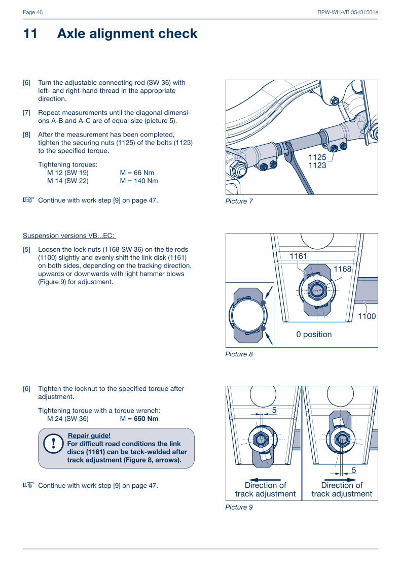
Suspension versions VB...EC:
[5] Loosen the lock nuts (1168 SW 36) on the tie rods (1100) slightly and evenly shift the link disk (1161) on both sides, depending on the tracking direction, upwards or downwards with light hammer blows (Figure 9) for adjustment.
[6] Tighten the locknut to the specifi ed torque after adjustment.
Tightening torque with a torque wrench: M 24 (SW 36) M = 650 Nm
Repair guide!
For diffi cult road conditions the link
discs (1161) can be tack-welded after
track adjustment (Figure 8, arrows).
� Continue with work step [9] on page 47.
BPW-WH-VB 35431501e Page 47
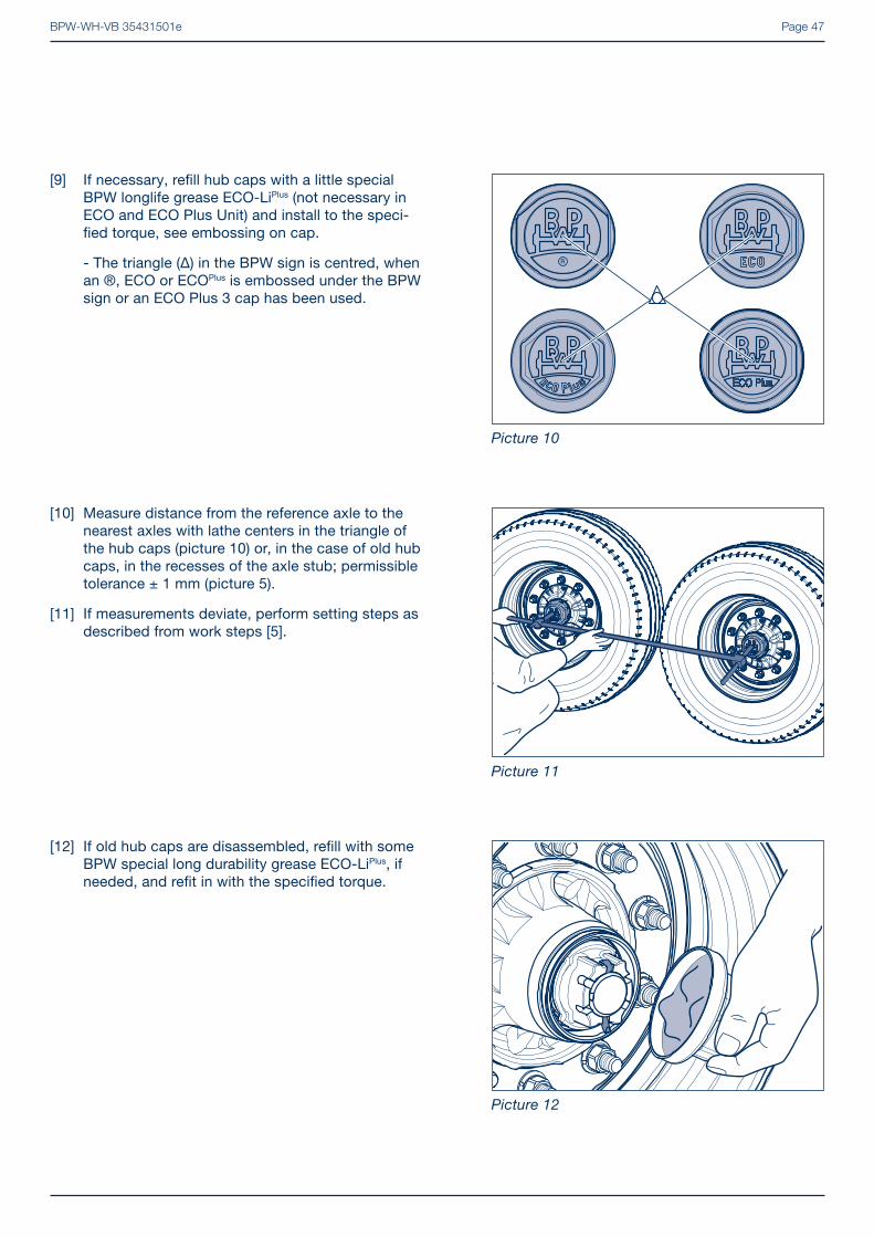
[10] Measure distance from the reference axle to the nearest axles with lathe centers in the triangle of the hub caps (picture 10) or, in the case of old hub caps, in the recesses of the axle stub; permissible tolerance ± 1 mm (picture 5).
[11] If measurements deviate, perform setting steps as described from work steps [5].
Picture 10
Picture 11
Picture 12
R
[9] If necessary, refi ll hub caps with a little special BPW longlife grease ECO-LiPlus (not necessary in ECO and ECO Plus Unit) and install to the speci-fi ed torque, see embossing on cap.
- The triangle (Δ) in the BPW sign is centred, when an ®, ECO or ECOPlus is embossed under the BPW sign or an ECO Plus 3 cap has been used.
[12] If old hub caps are disassembled, refi ll with some BPW special long durability grease ECO-LiPlus, if needed, and refi t in with the specifi ed torque.

BPW-WH-VB 35431501ePage 48
[1] Set up the laser in accordance with the manufacturer’s instructions. Make sure the axle is positioned horizontally to avoid camber values corrupting the measuring results.
Calculating the toe values:
Toe = A1 - B1 (mm) Positive value = Toe-in A (m) Negative value = Toe-out
[2] Perform the measurement on both sides and add together the measurement value. The total of the values is the toe-in/toe-out value of the axle and must be within the permitted tolerance range.
Permitted toe tolerance range per axle: for rigid axles: -1 to +5 mm/m for LL axles unladen: -2 to +2 mm/m laden: 0 to +6 mm/m
[3] Correct alignment in case of impermissible tolerance values (see chapter 11, from working step [5]).
Picture 1
12 Axle alignment check with laser measuring
devices
Picture 2
horizontal axle position

BPW-WH-VB 35431501e Page 49

BPW-WH-VB 35431501ePage 50
Notes

BPW-WH-VB 35431501e Page 51

BP
W-W
H-V
B 3
5431
501e
Your partner on the path to economic v iabi l i ty
BPW Bergische Achsen Kommanditgesellschaft
Postbox 12 80 · 51656 Wiehl, Germany · Phone +49 (0) 2262 [email protected] · www.bpw.de