word publishing template - us forest service · web viewthe same procedure is used for logs with...
TRANSCRIPT

FSScalerFSScalerUser’s GuideUser’s Guide
United States Department of Agriculture
Forest ServiceWashington Office
Forest Management Service CenterFort Collins, CO
Last Updated: 7/16/08

The U.S. Department of Agriculture (USDA) prohibits discrimination in all its programs and activities on the basis of race, color, national origin, sex, religion, age, disability, political beliefs, sexual orientation, or marital or family status. (Not all prohibited bases apply to all programs.) Persons with disabilities who require alternative means for communication of program information (Braille, large print, audiotape, etc.) should contact USDA’s TARGET Center at (202) 720-2600 (voice and TDD).To file a complaint of discrimination, write USDA, Director, Office of Civil Rights, Room 326-W, Whitten Building, 1400 Independence Avenue, SW, Washington, DC 20250-9410 or call (202) 720-5964 (voice or TDD). USDA is an equal opportunity provider and employer.

Table of Contents
Table of Contents..............................................................................................................iiiIntroduction........................................................................................................................1Chapter 1 – Installation.....................................................................................................3
Installation.....................................................................................................................3Filing Strategies and Safety...........................................................................................3
Chapter 2 – Getting Started..............................................................................................5Starting the Program......................................................................................................5Edit Existing Cruise.......................................................................................................5Create New File.............................................................................................................6Load Info.......................................................................................................................8
Chapter 3 – Scale File Type.............................................................................................11Production....................................................................................................................11Check Scale..................................................................................................................11Non-scale loads............................................................................................................11
Chapter 4 – Setup and Options......................................................................................13Landing Field...............................................................................................................14Change Fields..............................................................................................................14Change Lengths...........................................................................................................15Supervisor Mode..........................................................................................................16Make Setup File...........................................................................................................17Other Options...............................................................................................................18
Chapter 5 – Data Entry...................................................................................................19Chapter 6 – Reports.........................................................................................................23Chapter 7 – Future Enhancements................................................................................25Appendix A: Data Structure...........................................................................................27Appendix B: Segmentation Rules...................................................................................33
How Taper Is Assigned................................................................................................33Even Taper...................................................................................................................34
Two-Segment Log (even taper).............................................................................34Three-Segment Log (even taper)...........................................................................35Logs of Four or More Segments (even taper)........................................................35
Uneven Taper...............................................................................................................36Two-Segment Log (uneven taper).........................................................................36Three-Segment Logs (uneven taper).....................................................................37Logs of Four or More Segments............................................................................38
Appendix C: Cubic Foot Volume Calculation...............................................................39Rounding Rule.............................................................................................................39Cubic Foot Gross Volume............................................................................................39

Cubic Foot Defect Volume..........................................................................................40One-Segment Log (Length < 20)...........................................................................41Multi-Segment Log (Length > 20).......................................................................50
Appendix D: Board Foot Volume Calculation..............................................................55Board Foot Gross Volume............................................................................................55Board Foot Defect Volume..........................................................................................55
One-Segment Log (Length <= 20).......................................................................55For All Defects Excluding Volume Deductions...........................................................55
Multi-Segment Log (Length > 20)........................................................................56Board Foot Segment Defect Volume...........................................................................56Board Foot Net Volume...............................................................................................56
Appendix E: General Volume Formulae.......................................................................57Appendix F: Defect Codes Table....................................................................................59Appendix G: 3P Pseudo Random Number Algorithm.................................................61Works Referenced..............................................................................................................63
Introduction
FSscaler is the Windows/Windows CE successor to NATCDE, the MS-DOS based scaling system that has been used successfully for over ten years. FSscaler has been designed to be:
Small – around 1 MB Fast – no long delays during data entry Robust – virtually incorruptible data structure Intuitive – minimum training required to operate Universal – one cruise data file from cruise design through processing
This guide assumes the user has a working knowledge of the Windows Operating System and a basic understanding of the Windows CE Operating System.
FSscaler is available for the Juniper Allegro CE and Alegro CX data recorders. The PC version of FSscaler is also available for evaluation and training.
Throughout the document, some symbols are used to draw attention to important points and/or tips. These symbols are used as follows:
A topic or paragrah relevant to the PC version only.
A topic or paragraph relevenat to the FDR version only.
A tip, hint, or useful idea.
An important point or warning.
A critical point or possible error condition.
Questions or comments?
11

Questions, comments, and problems should be reported to:U.S. Forest Service: the forest or zone check cruiserOther agencies: the local measurements specialistsFMSC Contact: Matt Oberle 970.295.5752, e-mail: [email protected]

Chapter 1 – Installation
InstallationIf a Region or agency doesn’t provide specific installation instructions, please follow these general instructions:
FSscaler for both PC and FDR can be downloaded from:http://www.fs.fed.us.fmsc.measure/scaling/fsscaler/index.
Create a new folder “FSscaler” in the C:\fsapps\FMSC Software directory and copy the file “FSScaler.exe” into the folder. You may then create a shortcut on the desktop by right-clicking on “FSScaler.exe” and selecting Send to then Desktop (create shortcut) from the drop-down menus. IF you are a check scaler, copy the FSscaler.upw file into the “FSscaler” folder with the executable.
Create a new folder “FDR” in the C:\fsapps\FSscaler and copy the data recorder version of FSscaler into the folder. Using ActiveSync, copy the data recorder version of FSscaler.exe from your PC to the C_Drive\C_Program Files directory on your Allegro. If you are a check scaler, copy the FSscaler.upw file into C_Drive\C_Program Files with the executable. Copy the Sales.csv file into C_Drive\C_Program Files. Make a new folder in C_Drive\C_MyDocs called “Scale Files”. This is where scale data files will be stored.
Filing Strategies and SafetyAs with any data collection effort or PC use, a backup strategy is an integral part of the system. Because the scale files will sometimes exist on a PC as well as being downloaded to the data recorder, it is important that care be taken not to inadvertently overwrite one file with another.
Example: Rather than overwrite the PC file with the data recorder file or vice versa, rename the file first, perhaps with the date and then copy over the newer file.
Periodically backing up the cruise files to a server is a good idea; however, do not use FSscaler to open a file residing on a server. To work with a scale file stored on a server, copy it to a folder on the PC’s hard drive and open it from there.
The following topics step through the basic operation of FSscaler, from starting the program, opening a scale file and navigating to Header Information, Setup & Options,
Data Entry and Reports & Utilities. While the screen shots are primarily from the PC version, the operations also apply to the data recorder versions of FSscaler except where otherwise noted.

Chapter 2 – Getting Started
Starting the ProgramTo start FSscaler, use any of the common methods to start the program such as navigating to the folder where the program is stored and double clicking on “FSScaler.exe”, or by creating a shortcut to the program on the desktop. When the program starts, an FSScaler information screen will appear (Error: Reference source not found). Click OK to start FSScaler and the main menu screen will appear (Error: Reference source not found). At first, there will be no open file and there will be only two options available: Edit existing file or Create new file.
Edit Existing CruiseClicking the Edit existing file button opens a standard file selection dialog as shown in (Error: Reference source not found). Navigate to the desired file to open it. Double click the file name, or highlight the file and press the Enter key or the Open button. Notice the filename has 14 numbers followed by a “.scl” extension. In this example, this is a production scale file. The first eight numbers are the date the file was created while the remaining six numbers are the log load receipt number.
55
Figure 1Figure 1 - About FSscaler - About FSscaler Figure 2Figure 2 - FSscaler Main Menu - FSscaler Main Menu

The file will open, and the main menu screen will be displayed again, with the opened file’s path listed under the top row of buttons (Error: Reference source not found). The remaining buttons on the main dialog are now enabled. This is a production scale file as the droplist box at the center right of the main dialog indicates. It already contains log data, so the droplist box is disabled and the file type can’t be changed. This scale load hasn’t been finalized yet, so the Finalize load button is enabled.
Create New FileWhen creating a new scale file, FSscaler guides you through a multi-step process. After clicking the Create new file button, a standard File Browse dialog will appear (Error: Reference source not found). Use this dialog to navigate to the directory containing the Setup file you wish to use and select it. Setup files will have a “.SetupScl” extension.
Figure 3Figure 3 - Structure Update Message - Structure Update Message
Figure 4Figure 4 - Enabled Main Menu - Enabled Main Menu

After selecting the Setup file, a second File Browse dialog will appear (Error: Reference source not found). This is where you navigate to the directory where you want the new scale file created and where you enter the main part of the filename.
In this example, the new scale file will be created in the “Scale Files” folder. The file name will default to “000000.scl”. That is to prompt you to type in the log load receipt number for a production scale load. Simply start typing the new file name (the six digit log load receipt number) and it will overwrite the default name. Click the Save button or press Enter. When the file is created, the eight digit date will be automatically added to the beginning of the file name.
77
Figure 5Figure 5 - Create New File - Create New File
Figure 6Figure 6 - Browse Dialog - Browse Dialog

In this example, a log load receipt number of “654321” was entered, and the final file name will be “20050902654321.scl” if the date is September 2, 2005.
Load InfoNext, the file will be opened and you will be automatically taken to the Load Info dialog where header information for the load is entered (Error: Reference source not found). If a Sales.csv file has been put together and exists in the same directory as the executable (FSscaler.exe), the SALE field will be a droplist (the Sales.csv file is discussed in detail later in this document). In this example, double click on the SALE field, and a droplist of sales will appear (Error: Reference source not found).
Using your mouse or stylus, select the SALE for this new load, then click on one of the empty data cells below SALE and the information from the Sales.csv file for the selected sale will appear (Error: Reference source not found). Scroll down to enter your initials in the SCALER field (notice the log load receipt number is already entered if you entered it when first creating the new file). Enter truck weights and haul date if you have this information available, but you may enter this information later (Error: Reference source not found).
Figure 7Figure 7 - Load Info Dialog - Load Info Dialog Figure 8Figure 8 - SALE Field - SALE Field

For the final step after creating a new file, FSscaler automatically opens the sample design dialog (Error: Reference source not found). Here the scale type (Cubic) is and sampling method (3P or 100) is chosen. The KZ table must be filled out for the 3P sampling method. After entering the sample design information and clicking the OK button, you will return to the main menu (Error: Reference source not found). Since no log data has been entered yet, the file type droplist box is enabled. Here the scale file type of either production, check scale or non-scale loads is chosen. This example is a of a production scale so that is what is selected.
99
Figure 9Figure 9 - Edit Load Information - Edit Load Information Figure 10Figure 10 - SCALER and LLR Fields - SCALER and LLR Fields
Figure 11Figure 11 - Scale and Sample Setup - Scale and Sample Setup Figure 12Figure 12 - Main Menu Dropdown - Main Menu Dropdown

Chapter 3 – Scale File Type
ProductionThe most common type, a production scale file will contain log data for one scaled load.
Check ScaleA check scale file can contain log data for multiple loads. Each new check scaled load must have the appropriate load information (header) entered by clicking on the Load Info button (Error: Reference source not found).
The load information dialog for a check scale file will have navigation buttons at the right. Before beginning a new check scaled load, a new record must be added using the New button, and appropriate information for the load entered.
The log table in Data Entry will have the log load receipt (LLR) and SALE fields turned on for the first two columns. When a new load is to be check scaled, a new load information record is added, and the new LLR and SALE will appear in the droplists in the Data Entry log table. The check scaler would choose the appropriate LLR and SALE and begin entering logs for the new check scaled load. Both LLR and SALE are automatically copied to new records, so the check scaler only needs to re-select them when starting a new load. Log number is automatically incremented, so the check scaler will have to update new log numbers when entering sample logs from a 3P scaled load (Error: Reference source not found).
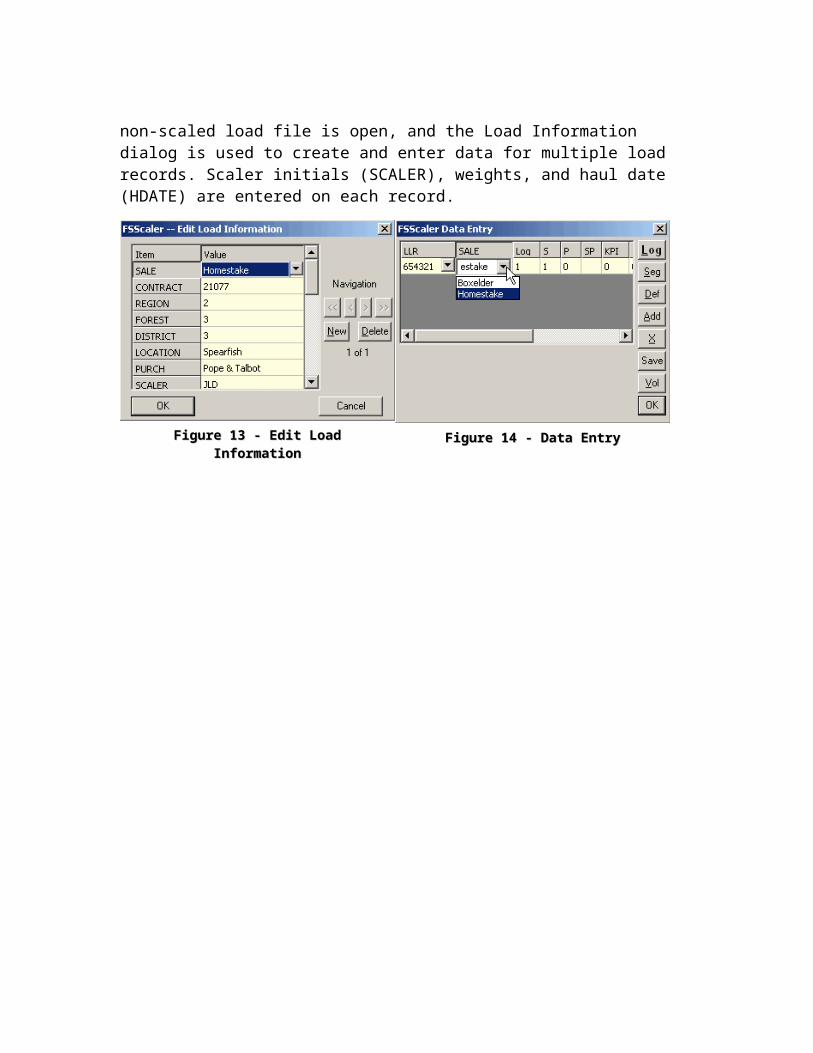
Non-scale loadsScalers and/or Resource Clerks have the option of entering non-scale load information in FSscaler by creating a non-scale load file. The Data Entry button is disabled when a non-scaled load file is open, and the Load Information dialog is used to create and enter data for multiple load records. Scaler initials (SCALER), weights, and haul date (HDATE) are entered on each record.

Figure 13Figure 13 - Edit Load Information - Edit Load Information Figure 14Figure 14 - Data Entry - Data Entry
Chapter 4 – Setup and Options
Chapter 4 – Setup and OptionsChapter 4 – Setup and Options
Clicking the Setup & Options button will display the options screen (Error: Reference source not found). This screen allows you to customize what is displayed for the headers information, log table, segment table and defect table. Use the pull down list to select what type of data (ie. Table to Customize) you want to customize. Notice that it defaults to the Log table, and there is a comma separated list of fields that will be displayed.
Landing FieldThe Landing Field droplist allows you to choose which field will become active each time a new log record is added.
Change FieldsIf you click the Change Fields button, a screen will appear that allows you can add or remove fields from the list of fields to be displayed, or to reorder the fields (Error: Reference source not found).
Figure 15Figure 15 - Setup and Options - Setup and Options

Chapter 4 – Setup and OptionsChapter 4 – Setup and Options
To display a field in the data collection table, click on any field in the Available list then the Include> button to move the field to the Selected list. Clicking the All>> button will move all fields from the Available list to the Selected list. You can also remove a field from the Selected list by clicking the <Exclude button. Clicking either the Up or Down buttons will reorder the list of fields. Note that only the display information is changing, and that the field is still present in the table on file.
When the selection is completed, accept the changes and return to the setup screen by clicking the OK button. To cancel the selections, click the Cancel button.
Change LengthsTo change the display length, the default value (for new records), and the validation list fields, click the Change Length button to bring up the Change Field Lengths dialog (Error: Reference source not found).
Figure 16Figure 16 - Change Fields - Change Fields
Figure 17Figure 17 - Change Field Lengths - Change Field Lengths

Chapter 4 – Setup and OptionsChapter 4 – Setup and Options
This table displays the column name, the description of the field, the length of the field, the default value and validation list. The last three fields are the only editable columns in this table. Changing the length field will not affect what is stored on the file, but will change how many characters will be displayed. Also, when this number of characters is reached during data entry, the cursor will move to the next field. The second editable column contains a default action that will fill in a default value when new records are created for the table. If a “C” is entered in the specification, the value from the previous record will be copied. If an “I” is entered, then the value from the previous record will be incremented. If a “V”, followed by any string of characters (any character or number with no spaces allowed), is entered, then that constant value will be placed in the field. The final entry is for a validation list for the field; enter the legal values for the field as a space delimited list of values; spaces separate values, and thus any single value in the list cannot have any spaces.
Please note that when you create a new file, that new file will always inherit from a default setup file of your choice. In general, the “DefaultScaler.Setup” file that was distributed with the program will be used, or some file derived from the default. Make a backup copy of this file, and open it up and customize the way you want it, and this will then be the starting point when you begin a new scale file. In this way, you can have lots of different starting points, similar to the way that FScruiser has different setup files. Just create any number of defaults that you want and select one of them to be used as the starting point.
Supervisor ModeClicking the Supervisor button on the Setup and Options screen will bring up a prompt asking for a username and password (Error: Reference source not found). After clicking Sign in, the entered username and password are cross referenced with valid username and password pairs in the file “FScruiser.upw”. If a valid username and password is entered, you will be signed in to supervisor mode as your username. If the FScruiser.upw file is opened in a text editor, the password(s) are encrypted and unreadable, and cannot be changed.

Chapter 4 – Setup and OptionsChapter 4 – Setup and Options
The file FScruiser.upw must exist in the same directory as FSscaler.exe or the following error message will be displayed:
Supervisors or check scalers can contact Matt Oberle from the Forest Management Service center for their FScruiser.upw. Once received and installed, change your password and do not share it with anyone.
After successfully logging into supervisor mode, a new audit report can be created from the scale file, a production scale file can be un-finalized, a new user can be added, and the current user’s password can be changed.
Make Setup FileClicking the Make Setup File button will display a generic save prompt (Error: Referencesource not found). Enter the desired file name and either press Enter or click the Save button. A new window will appear stating that a new setup file was created, and will display the path on the hard drive (Error: Reference source not found).
Figure 18Figure 18 - Username and Password Input - Username and Password Input

Chapter 4 – Setup and OptionsChapter 4 – Setup and Options
Other Options
Figure 19Figure 19 - Make Setup File - Make Setup File
Figure 20Figure 20 - New Setup File Created - New Setup File Created
Figure 21Figure 21 - Other Options - Other Options

Chapter 5 – Data Entry
Clicking the Enter Data button from the main menu will make a window appear where the actual scale data entry process begins ().
This example contains the cubic test logs. Again, only the fields selected in the setup appear in the table. Fill in the data for the log as you need. Then to edit segment data for any log, move to the log in the log table and hit the Seg button, or just type an “S” from any numeric field (letters are accepted as data input if you are in an alpha field). You will then see the following addition to the dialog:
Notice that the first four columns in the segment table are yellow and are not editable; these fields are calculated from the log measurements. Segments are created and
Figure 22Figure 22 - Data Entry - Data Entry
Figure 23Figure 23 - Data Entry (Segment) - Data Entry (Segment)

Chapter 4 – Setup and OptionsChapter 4 – Setup and Options
numbered automatically, thus you cannot add or delete any segments manually. In many situations, you will never need to even need to display segment information, but simply enter defect information.
From either the log or segment table, enter a defect by hitting the Def button, or hitting the letter “D” while in a numeric field. You will then see the defect table:
Enter the defects for the segment (segment field will be 1…n), or if the defect is for the log (segment will be 0). The measurement fields M1 to M4 depend on the defect as to what is filled in. At any point during the data entry, you can get a report of the calculated volume of the current log by tapping the ‘Vol’ button or hitting the ‘V’ key. Presently, only the cubic volume calculations have been implemented. You should see a dialog with the summary information:
While in Data Entry, a load summary can be viewed at any time by pressing F2:
Figure 24Figure 24 - Data Entry (Defect) - Data Entry (Defect)
Figure 25Figure 25 - Log Volume Information - Log Volume Information

Figure 26Figure 26 - Load Summary - Load Summary

Chapter 6 – Reports
Clicking the Reports button generates comprehensive (cmp), cubic log (clg) and NatScale Cubic input (nsc) files for the production load, or for all loads with a check scale file. A message box will appear after a short delay:
The new report files will be placed in the directory containing the open scale file:
Notepad doesn’t recognize page breaks, so if you want to print the report you’ll need to use a program that does, such as PFE Programmer’s File Editor (PFE). PFE can be downloaded from the ‘Utilities’ folder on our ftp site.
Figure 27Figure 27 - Reports Generated - Reports Generated
Figure 28Figure 28 - Report Files Directory - Report Files Directory

Figure 29Figure 29 - Report Output - Report Output

Chapter 7 – Future Enhancement
Scribner and long log scaling data entry and reports. A check scale program that will take a log load’s production scale file and check
scale file, compare them and create reports. A conversion program to convert legacy cubic.exe out files to scl files. Add the ability to use custom taper tables for butt log diameter calculations. Add a dynamic log diagram to the data entry screen.

Appendix A: Data Structure
Data is collected into the following tables. The load level information is in the load table and will generally only have one record per file, since there will be a separate file for each load (a single file could have multiple loads the way the tables are structured). The log table contains one record for each log in the load. This will be the main input area. The segment table will contain one record for each segment within each log. So, if you had 10 logs, each with two segments, there would be 20 segment records (although you will only see the segments for the current log). Defects can be entered directly on the segment record in cubic or board feet if you know what they are, or can be tracked and recorded separately; this should make check scaling more track able since there should be no question about how the log/segment was defected. There will be one record for each defect in each log/segment.
The general structure of the metadata includes the Type of data for the field; indicates if integer, string, or real number. The Title is what will appear as the column heading in the data entry screen; this needs to be short so it shows on the heading. The Description is a short note about what the field contains. The Length is the number of characters or width of the edit field. The grid is set up to automatically move after that number of characters is entered. The Default column indicates if the initial value for a new record will be a constant value, copied from the previous, or incremented from the previous. Once a record is created, the default values can be changed (except of course for things like the segment measurements). The Display column is the currently selected fields and order that will be displayed. Changing the values for this metadata will control what the user will see; no more hard code programming to change many of these features.

Appendix A: Data StructureAppendix A: Data Structure
LoadLoad Table TableType Description Title Length Default DisplayS Sale ID SALE 3 C 0S Sale Name SALENAME 8 C 0S Contract CONTRACT 7 C 0S Location LOCATION 8 C 0S Purchaser PURCH 8 C 0S Region REGION 2 C 0S Forest FOREST 2 C 0S District DISTRICT 2 C 0S Load Receipt LLR 7 0S Truck ID TRK 7 0S Brand BRAND 5 0F Gross Weight (lbs) GWT 8 0F Tare Weight (lbs) TWT 8 0F Net Weight (lbs) NWT 8 0S Scale Date SDATE 8 0S Scale Time STIME 8 0S Haul Date HDATE 8 0S Haul Time HTIME 8 0S Scaler SCALER 5 0S Remark REM 8 0S Sample Group (sort) SG 2 0S Sapmle Type ST 3 C 0S Measurement System MEASSYS 1 C 0F Merch Spec Saw MERCHSAW 5 C 0F Merch Spec Non-Saw MERCHNONSAW 5 C 0I Minimum Length MINLEN 2 V8 0I Maximum Length MAXLEN 2 V50 0I Minimum Diameter MINDIA 2 V5 0I Maximum Diameter MAXDIA 2 V60 0S Load status (O)pen (L)ocked (C)heck STATUS 1 VO 0S BIA scale unit ownership BIAUNIT 5 0S Destination DEST 8 0

Appendix A: Data StructureAppendix A: Data Structure
Load TableLoad TableType Description Title Length Default DisplayS Sale ID SALE 3 C 0S Load Receipt LLR 7 C 0I Log number/ID Log 3 I 1I Split sublog number S 1 2S Species SP 2 C 3I Log Length LN 2 5I Small end diameter SD 2 6I Large end diameter LD 2 7I Product P 1 4I Grade G 1 0S Butt B 1 0I KPI prediction KPI 3 0I Random Number RND 3 0I Hit Code H 1 0S Remarks REM 8 8I Void VOID 1 V0 0I Cubic Squared area defect SAC 2 0I Cubic Length cut defect LCC 2 0I Cubic Diameter defect DC 2 0I Cubic Percent defect PC 2 0I Cubic Ring defect RC 2 0I Board Squared area defect SAB 2 0I Board Length cut defect LCB 2 0I Board Diameter defect DB 2 0I Board Percent defect PB 2 0I Board Ring defect RB 2 0I Cubic abnormal delay add back ABC 3 0I Board abnormal delay add back ABB 3 0F Calculated Gross cubic volume GCV 5 0F Calculated Net cubic volume NCV 5 0F Calculated Gross board volume GBV 5 0F Calculated Net board volume NBV 5 0

Appendix A: Data StructureAppendix A: Data Structure
Segment TableSegment TableType Description Title Length Default DisplayS Sale ID SALE 3 C 0S Load Receipt LLR 7 C 0I Log number/ID Log 3 C 0I Split sublog number S 1 C 0I Segment number/ID Seg 1 I 1I Segment Length LN 2 2I Small end diameter SD 2 3I Large end diameter LD 2 4I Void flag VOID 1 V0 0S Remarks REM 8 5I Cubic Squared area defect SAC 2 6I Cubic Length cut defect LCC 2 7I Cubic Diameter defect DC 2 8I Cubic Percent defect PC 2 9I Cubic Ring defect RC 2 10I Board Squared area defect SAB 2 0I Board Length cut defect LCB 2 0I Board Diameter defect DB 2 0I Board Percent defect PB 2 0I Board Ring defect RB 2 0I Cubic abnormal delay add back ABC 3 0I Board abnormal delay add back ABB 3 0F Calculated Gross cubic volume GCV 5 0F Calculated Net cubic volume NCV 5 0F Calculated Gross board volume GBV 5 0F Calculated Net board volume NBV 5 0

Appendix A: Data StructureAppendix A: Data Structure
Cubic Defect TableCubic Defect TableType Description Title Length Default DisplayS Sale ID SALE 3 C 0S Load Receipt LLR 7 C 0I Log number/ID Log 3 C 0I Segment (log) where defect occurs Seg 1 C 1I Check scaler defect CHKDEF 1 C 0I Defect method M 1 2S Defect type T 1 3I Measurement 1 M1 2 4I Measurement 2 M2 2 5I Measurement 3 M3 2 6I Measurement 4 M4 2 7I Length deduction LN 2 8I Percent deduction PCT 2 9I Percent fiber deduction PF 2 10F Entered Defect cubic volume DV 3 0F Calculated Defect cubic volume CDV 3 0S Remarks REM 8 0I Void flag VOID 1 V0 0I Add back percent (0-none 1-all else-%) AB 1 V0 0
Board Defect TableBoard Defect TableType Description Title Length Default DisplayS Sale ID SALE 3 C 0S Load Receipt LLR 7 C 0I Log number/ID Log 3 C 0I Segment (log) where defect occurs Seg 1 C 1I Check scaler defect CHKDEF 1 C 0I Defect method M 1 2S Defect type T 1 3I Measurement 1 M1 2 4I Measurement 2 M2 2 5I Measurement 3 M3 2 6I Measurement 4 M4 2 7I Length deduction LN 2 8I Percent deduction PCT 2 9I Percent fiber deduction PF 2 10F Entered Defect board volume DV 3 0F Calculated Defect board volume CDV 3 0S Remarks REM 8 0I Void flag VOID 1 V0 0I Add back percent (0-none 1-all else-%) AB 1 V0 0

Appendix B: Segmentation Rules
The number of segments, segment lengths, and segment positions within the log are calculated from the recorded length by using the rules in the National Forest Cubic Scaling Handbook (FSH 2409.11a, 1991).
The rules mentioned above were extended to determine values for lengths up to 99 feet. Only lengths up to 99 feet can be recorded.
How Taper Is AssignedDefinition: Taper is defined as the progressive change in a measurement from one end, or point on its length, to another.
Notes: TAPER is EVEN when it can be apportioned in an equal amount to each segment and UNEVEN when it cannot. For additional information on how taper is assigned, see the sections on distributing even/uneven taper in the National Forest Cubic Scaling Handbook (FSH 2409.11a).
TAPER = (Large End Diameter) – (Small End Diameter)

Appendix B: Segmentation RulesAppendix B: Segmentation Rules
Even Taper
Two-Segment Log (even taper)
To obtain the Middle Diameter (MD), the taper is divided by two (the number of segments) and the result is added to the Small End Diameter (SED).
Example:LED (Large End Diameter) = 16SED (Small End Diameter) = 10TAPER = LED – SED
TAPER = 16 – 10 = 6TAPER per SEGMENT = TAPER / (# of Segments)
TAPER per SEGMENT = 6 / 2 = 3MD (Middle Diameter) = SED + TAPER per SEGMENT
MD = 10 + 3 = 13

Appendix B: Segmentation RulesAppendix B: Segmentation Rules
Three-Segment Log (even taper)
The total taper is divided by three (the number of segments) and the result is the amount of taper assigned to the top segment. The remainder of the taper is distributed as in a two-segment log. As a check, the top diameter of the bottom segment will differ from the large end diameter (LED) by the taper per segment.
Example:LED (Large End Diameter) = 20SED (Small End Diameter) = 14TAPER = LED – SED
TAPER = 20 – 14 = 6TAPER per SEGMENT = TAPER / (# of Segments)
TAPER per SEGMENT = 6 / 3 = 2MD2 (Middle Diameter 2) = SED + TAPER per SEGMENT
MD2 = 14 + 2 = 16MD1 (Middle Diameter 1) = MD2 + TAPER per SEGMENT
MD1 = 16 + 2 = 18
Logs of Four or More Segments (even taper)The total taper is divided by the number of segments and the resulting taper per segment is added to the small end diameter to obtain the top diameter of the second segment. The taper per segment is then added, in turn, to each top diameter until all top diameters are calculated. As a check, the top diameter of the bottom segment will differ from the large end diameter by the taper per segment.

Appendix B: Segmentation RulesAppendix B: Segmentation Rules
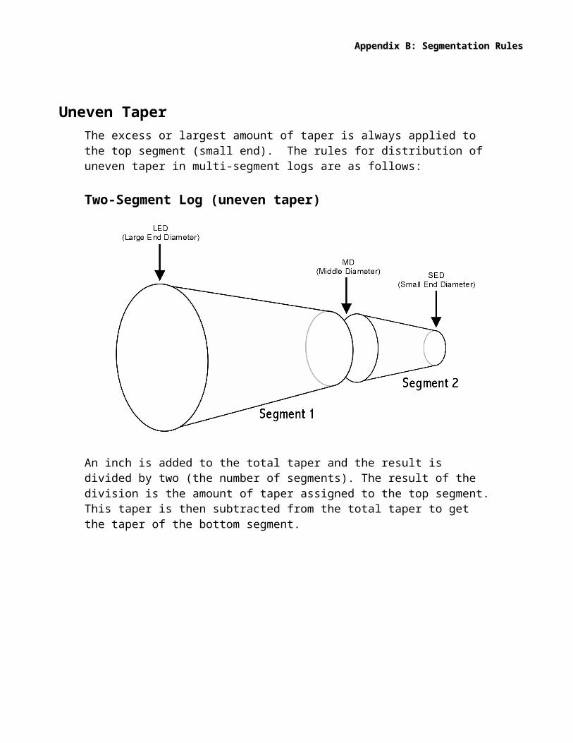
Uneven TaperThe excess or largest amount of taper is always applied to the top segment (small end). The rules for distribution of uneven taper in multi-segment logs are as follows:
Two-Segment Log (uneven taper)
An inch is added to the total taper and the result is divided by two (the number of segments). The result of the division is the amount of taper assigned to the top segment. This taper is then subtracted from the total taper to get the taper of the bottom segment.
Example:LED (Large End Diameter) = 30SED (Small End Diameter) = 25TAPER = LED – SED
TAPER = 30 – 25 = 5TAPER per SEGMENT = (TAPER + 1) / (# of Segments)
TAPER per SEGMENT = 6 / 2 = 3TAPER for SEGMENT 1 = TAPER – TAPER per SEGMENT
TAPER for SEGMENT 1 = 5 – 3 = 2MD (Middle Diameter) = SED + TAPER per SEGMENT
MD = 25 + 3 = 28

Appendix B: Segmentation RulesAppendix B: Segmentation Rules
Three-Segment Logs (uneven taper)
The total taper is raised to a number divisible by three (the number of segments) and divided. The result is the amount of taper assigned to the top segment. The remainder of the taper is distributed as in a two-segment log.
Example:LED (Large End Diameter) = 30SED (Small End Diameter) = 23TAPER = LED – SED
TAPER = 30 – 23 = 7 (uneven taper)Raise TAPER to a number divisible by 3 (# of log segments)
TAPERadj = 7 + 2 = 9 (divisible by 3)TAPER for SEGMENT 3 = TAPERadj / (# of Segments)
TAPER for SEGMENT 3 = (7 + 2) / 3 = 9 / 3 = 3REMAINING TAPER = TAPER – TAPER for SEGMENT 3
REMAINING TAPER = 7 – 3 = 4Distribute Remaining Taper as a Two-Segment Log:TAPER for SEGMENT 2 = REMAINING TAPER / (# of Remaining Segments)
TAPER for SEGMENT 2 = 4 / 2 = 2TAPER for SEGMENT 1 = REMAINING TAPER – TAPER for SEGMENT 2
TAPER for SEGMENT 1 = 4 – 2 = 2MD2 (Middle Diameter 2) = SED + TAPER for SEGMENT 3
MD2 = 23 + 3 = 26MD1 (Middle Diameter 1) = MD2 + TAPER for SEGMENT 2
MD1 = 26 + 2 = 28

Appendix B: Segmentation RulesAppendix B: Segmentation Rules
Logs of Four or More SegmentsFor four-segment logs, the total taper is raised to a number divisible by four (the number of segments) and divided. The result is the amount of taper assigned to the top segment. The taper in the top segment is subtracted from the total taper and the remaining taper is distributed as in a three-segment log. The same procedure is used for logs with more than four segments. Divide by the number of segments, working with one segment at a time, until a three-segment log is reached. The excess (greatest) taper is always applied to the top segment (small end).

Appendix C: Cubic Foot Volume Calculation
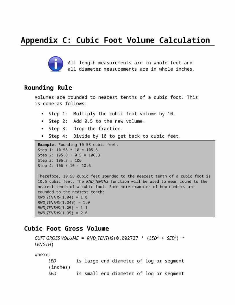
All length measurements are in whole feet and all diameter measurements are in whole inches.
Rounding RuleVolumes are rounded to nearest tenths of a cubic foot. This is done as follows:
Step 1: Multiply the cubic foot volume by 10. Step 2: Add 0.5 to the new volume. Step 3: Drop the fraction. Step 4: Divide by 10 to get back to cubic feet.
Example: Rounding 10.58 cubic feet.Step 1: 10.58 * 10 = 105.8Step 2: 105.8 + 0.5 = 106.3Step 3: 106.3 → 106Step 4: 106 / 10 = 10.6
Therefore, 10.58 cubic feet rounded to the nearest tenth of a cubic foot is 10.6 cubic feet. The RND_TENTHS function will be used to mean round to the nearest tenth of a cubic foot. Some more examples of how numbers are rounded to the nearest tenth:RND_TENTHS(1.04) = 1.0RND_TENTHS(1.049) = 1.0RND_TENTHS(1.05) = 1.1RND_TENTHS(1.95) = 2.0
Cubic Foot Gross VolumeCUFT GROSS VOLUME = RND_TENTHS(0.002727 * (LED2 + SED2) * LENGTH)
where:LED is large end diameter of log or segment (inches)SED is small end diameter of log or segment (inches)LENGTH is length of log or segment (feet); where LENGTH < 20
Example: Let LED = 18 inches, SED = 16 inches, and LENGTH = 20 feet.
CUFT GROSS VOLUME = RND_TENTHS(0.002727 * (182 + 162) * 20)CUFT GROSS VOLUME = RND_TENTHS(0.002727 * (580) * 20)CUFT GROSS VOLUME = RND_TENTHS(31.6332)CUFT GROSS VOLUME = 31.6 ft3

Appendix B: Segmentation RulesAppendix B: Segmentation Rules
Cubic Foot Defect VolumeGross, net, and defect volumes are always determined for logs or log segments that are 20 feet or less in length. If a log is over 20 feet in length and defects that are recorded on the log ends extend the length of the log, then section 2b has the procedures to distribute the log defect measurements to each segment in the log. Subsequently, the procedures in section 2a are used to determine the defect volume in each section of the log.
Defects are identified by a primary method for purposes of volume calculation. In addition to the primary defect method calculation to be used, additional constraints can be placed on the defect amount. For example, it might be necessary to take a diameter deduction of 2 inches for a log segment, but that diameter deduction may only apply to 8 feet of the log and for half the circumference of that 8 feet. In this case, the defect deduction would be recorded as a diameter deduction of 2 inches for a length of 8 feet and only 50% of that amount. Table 1 shows the allowable combinations of measurements that may be applied to each defect method for a log or log segment 20 feet or less in length.
Table Table 11: Defect Measurement Combinations: Defect Measurement CombinationsMethod Code M1 M2 M3 M4 Length PercentLength Cut 1 N N N N Y NDiameter Cut 2 Y N N N Y* Y*Squared Area 3 Y Y* Y* Y* Y* Y*Percent Deduction 4 N N N N Y* YRings 5 Y Y* Y* Y* Y* Y*where:
Y = YesN = No* = Optional** = Optional, can be entered in place of M1
Appendix C: Cubic Foot Volume CalculationAppendix C: Cubic Foot Volume Calculation
One-Segment Log (Length < 20)
Length Deduction (Defect Method 1)
CUFT DEFECT VOLUME = CUFT GROSS VOLUME * (LD / LENGTH)
where:LD is the amount of length deductionLENGTH is total length of log or segment (feet); where LENGTH < 20
If CUFT DEFECT VOLUME is less than 0.2 cubic feet, then it is set to zero. Otherwise, the CUFT DEFECT VOLUME is rounded to the nearest tenth of a cubic foot.
Example: Let LED = 18 inches, SED = 16 inches, LENGTH = 20 feet, and LD = 6 feet
CUFT GROSS VOLUME = 31.6 ft3 (as in above example)CUFT DEFECT VOLUME = 31.6 * (6 / 20)CUFT DEFECT VOLUME = 31.6 * (0.3)CUFT DEFECT VOLUME = 9.48 ft3
RND_TENTHS(CUFT DEFECT VOLUME) = RND_TENTHS(9.48) = 9.5CUFT DEFECT VOLUME = 9.5

Appendix C: Cubic Foot Volume CalculationAppendix C: Cubic Foot Volume Calculation
Diameter Deduction (Defect Method 2)
DIAMETER DEDUCTION applies to both the large end and small end diameters as follows:
DIAM1 = LARGE END DIAMETER – DiameterDeductionDIAM2 = SMALL END DIAMETER – DiameterDeduction
If a length affected by the diameter deduction was entered, then convert the length affected to a percentage of the log length:
LengthPercent = LD / LENGTHotherwise:LengthPercent = 1
If a percent of the area affected by the diameter deduction was entered, then convert the percent affected to a decimal value:
DefectPercent = (% of AREA AFFECTED) * 0.01otherwise:DefectPercent = 1
CORE VOLUME = RND_TENTHS(0.002727 * (DIAM12 + DIAM22) * LENGTH)

Appendix C: Cubic Foot Volume CalculationAppendix C: Cubic Foot Volume Calculation
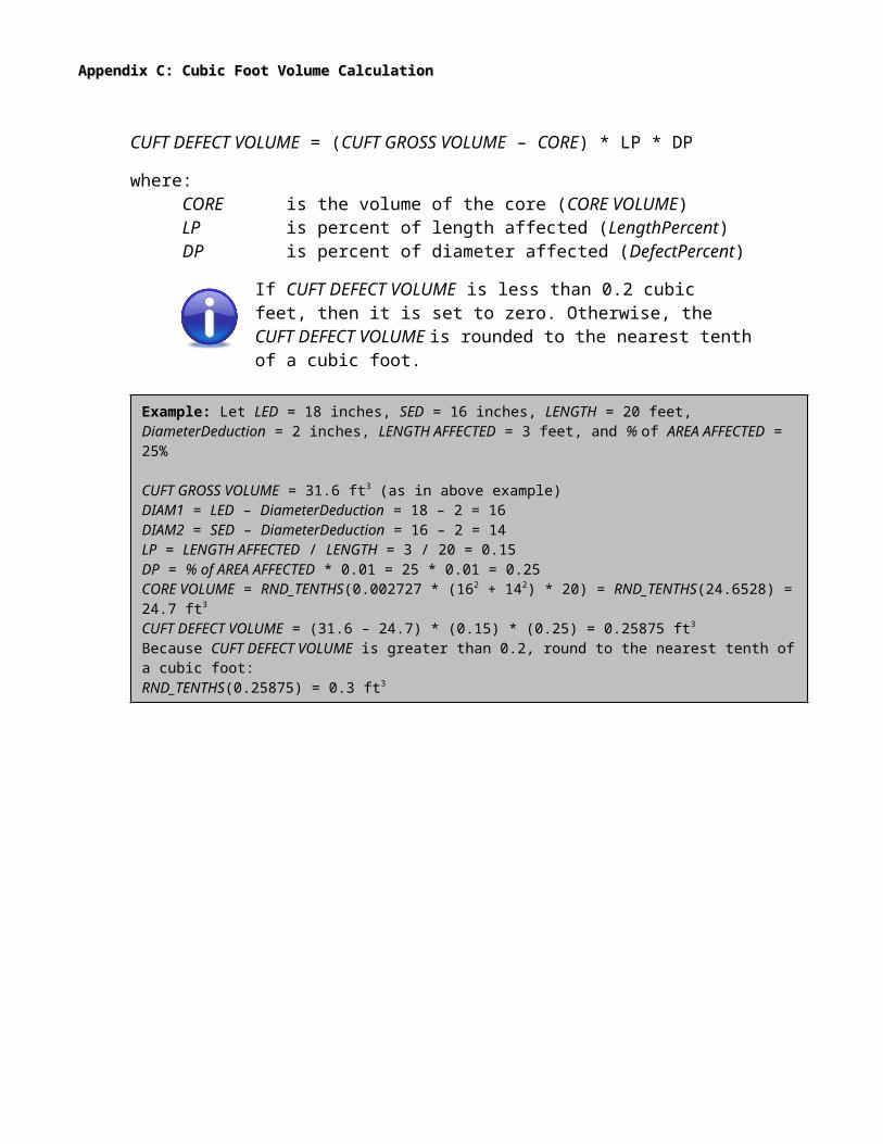
CUFT DEFECT VOLUME = (CUFT GROSS VOLUME – CORE) * LP * DP
where:CORE is the volume of the core (CORE VOLUME)LP is percent of length affected (LengthPercent)DP is percent of diameter affected (DefectPercent)
If CUFT DEFECT VOLUME is less than 0.2 cubic feet, then it is set to zero. Otherwise, the CUFT DEFECT VOLUME is rounded to the nearest tenth of a cubic foot.
Example: Let LED = 18 inches, SED = 16 inches, LENGTH = 20 feet, DiameterDeduction = 2 inches, LENGTH AFFECTED = 3 feet, and % of AREA AFFECTED = 25%
CUFT GROSS VOLUME = 31.6 ft3 (as in above example)DIAM1 = LED – DiameterDeduction = 18 – 2 = 16DIAM2 = SED – DiameterDeduction = 16 – 2 = 14LP = LENGTH AFFECTED / LENGTH = 3 / 20 = 0.15DP = % of AREA AFFECTED * 0.01 = 25 * 0.01 = 0.25CORE VOLUME = RND_TENTHS(0.002727 * (162 + 142) * 20) = RND_TENTHS(24.6528) = 24.7 ft3
CUFT DEFECT VOLUME = (31.6 – 24.7) * (0.15) * (0.25) = 0.25875 ft3
Because CUFT DEFECT VOLUME is greater than 0.2, round to the nearest tenth of a cubic foot:RND_TENTHS(0.25875) = 0.3 ft3
Appendix C: Cubic Foot Volume CalculationAppendix C: Cubic Foot Volume Calculation
Squared Area (Defect Method 3)
M1 = Large End Defect WidthM2 = Large End Defect HeightM3 = Small End Defect WidthM4 = Small End Defect Height
If a length affected by the squared area was entered:
LD = LENGTH AFFECTEDotherwise:LD = TOTAL LENGTH
If a percent of the area affected by the squared area was entered, then convert the percent affected to a decimal value:
DefectPercent = (% of SQUARE AREA AFFECTED) * 0.01otherwise:DefectPercent = 1
Table Table 22: Log Squared Area Measurements – One Segment: Log Squared Area Measurements – One Segment
Measurements Recorded How variables are set for the defect formulaWD HT
M1 M1 M1M3 M3 M3M1 & M2 M1 M2M3 & M4 M3 M4M1 & M3 RI ((M1 + M3) / 2) RI ((M1 + M3) / 2)M1, M2, M3 & M4 RI ((M1 + M3) / 2) RI ((M2 + M4) / 2)
Appendix C: Cubic Foot Volume CalculationAppendix C: Cubic Foot Volume Calculation
where: RI = rounded to the nearest even integer for values containing a fraction.
CUFT DEFECT VOLUME = ((WD * HT * LD) / 144)* DP
CUFT DEFECT VOLUME = (CUFT GROSS VOLUME – CORE) * LP * DP
where:WD, HT are determined by using Table 2 LD is the length affectedDP is percent of diameter affected (DefectPercent)
If CUFT DEFECT VOLUME is less than 0.2 cubic feet, then it is set to zero. Otherwise, the CUFT DEFECT VOLUME is rounded to the nearest tenth of a cubic foot.
Example: Let LENGTH = 20 feet, LENGTH AFFECTED = 16 feet, M1 = 10 inches, M2 = 14 inches, M3 = 5 inches, M4 = 8 inches, and % of SQUARED AREA AFFECTED = 75%
Calculate the average defect width by adding M1 and M3 together and dividing by 2:WD = RI((M1 + M3) / 2) = RI((10 + 5) / 2) = RI(15 / 2) = RI(7.5) = 8 inchesHT = RI((M2 + M4) / 2) = RI((14 + 8) / 2) = RI(22 / 2) = RI(11) = 11 inchesLD = LENGTH AFFECTED = 16 ftDP = % of SQUARED AREA AFFECTED = 75 * 0.01 = 0.75CUFT DEFECT VOLUME = ((8 * 11 * 16) / 144) * 0.75 = 7.333…ft3
RND_TENTHS(CUFT DEFECT VOLUME) = RND_TENTHS(7.333…) = 7.3 ft3

Appendix C: Cubic Foot Volume CalculationAppendix C: Cubic Foot Volume Calculation
Percent Deduction (Defect Method 4)
If a length affected by the percent deduction was entered, then convert the length affected to a percentage of the log length:
LP = LENGTH AFFECTED / LENGTHotherwise:LP = 1
Convert the percent deduction to a decimal value:DP = PERCENT AFFECTED * 0.01
CUFT DEFECT VOLUME = CUFT GROSS VOLUME * LP * DP
If CUFT DEFECT VOLUME is less than 0.2 cubic feet, then it is set to zero. Otherwise, the CUFT DEFECT VOLUME is rounded to the nearest tenth of a cubic foot.
Example: Let LED = 18 inches, SED = 16 inches, LENGTH = 20 feet, LENGTH AFFECTED = 10 feet, and PERCENT AFFECTED = 25%
LP = LENGTH AFFECTED / LENGTH = 10 / 20 = 0.5DP = PERCENT AFFECTED * 0.01 = 25 * 0.01 = 0.25CUFT GROSS VOLUME = 31.6 ft3 (from examples above)CUFT DEFECT VOLUME = 31.6 * 0.5 * 0.25 = 3.95 ft3
RND_TENTHS(CUFT DEFECT VOLUME) = RND_TENTHS(3.95) = 4.0 ft3

Appendix C: Cubic Foot Volume CalculationAppendix C: Cubic Foot Volume Calculation
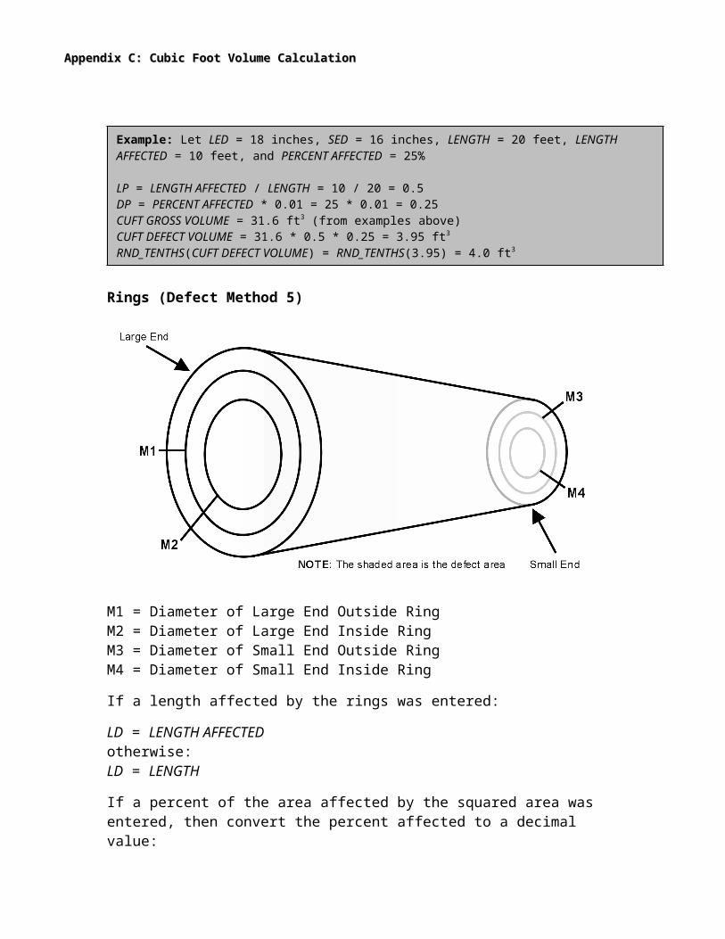
Rings (Defect Method 5)
M1 = Diameter of Large End Outside RingM2 = Diameter of Large End Inside RingM3 = Diameter of Small End Outside RingM4 = Diameter of Small End Inside Ring
If a length affected by the rings was entered:
LD = LENGTH AFFECTEDotherwise:LD = LENGTH
If a percent of the area affected by the squared area was entered, then convert the percent affected to a decimal value:
DP = (% of AREA AFFECTED) * 0.01otherwise:DP = 1
Table Table 33: Log Ring Measurements – One Segment: Log Ring Measurements – One Segment
Measurements RecordedHow variables are set for formula
D1 D2 D3 D4M1 M1 * M1 N/A M1 * M3 N/AM3 M3 * M3 N/A M3 * M3 N/AM1 & M3 M1 * M1 N/A M3 * M3 N/AM1, M2, M3 & M4 M1 * M1 M2 * M2 M3 * M3 M4 * M4
For the first three cases in table 3:

Appendix C: Cubic Foot Volume CalculationAppendix C: Cubic Foot Volume Calculation
CUFT DEFECT VOLUME = RND_TENTHS((D1 + D3) * LENGTH * 0.002727) * 0.273 * DP
The constant 0.273 is used to determine the difference in area between a square with side = X and a circle with diameter = X.
If CUFT DEFECT VOLUME is less than 0.2 cubic feet, then it is set to zero. Otherwise, the CUFT DEFECT VOLUME is rounded to the nearest tenth of a cubic foot.
Example: Let LED = 18 inches, SED = 16 inches, LENGTH = 20 ft, M1 = 8 inches, and M3 = 5 inches.
D1 = M1 * M1 = 8 * 8 = 64D2 = M3 * M3 = 5 * 5 = 25LP = LENGTH = 20DP = 1CUFT DEFECT VOLUME = RND_TENTHS((64 + 25) * 20 * 0.002727) * 0.273 * 1.0 = RND_TENTHS(4.85406) * 0.273 = 4.9 * 0.273 = 1.3377 ft3
RND_TENTHS(CUFT DEFECT VOLUME) = RND_TENTHS(1.3377) = 1.3 ft3

Appendix C: Cubic Foot Volume CalculationAppendix C: Cubic Foot Volume Calculation
For the last case in table 3:
Step 1: Determine the core volume of the outer ring:CORE1 = RND_TENTHS((D1 + D3) * LENGTH * 0.002727)
Step 2: The volume of the square of the outer core:SQUARE = CORE1 * 1.273
Step 3: The core volume of the inner ring:CORE2 = RND_TENTHS((D2 + D4) * LENGTH * 0.002727)
Step 4: The defect volume is calculated:CUFT DEFECT VOLUME = (SQUARE – CORE 2) * DP
If CUFT DEFECT VOLUME is less than 0.2 cubic feet, then it is set to zero. Otherwise, the CUFT DEFECT VOLUME is rounded to the nearest tenth of a cubic foot.
Example: Let LED = 18 inches, SED = 16 inches, LENGTH = 20 feet, M1 = 8 inches, M2 = 5 inches, M3 = 4 inches, and M4 = 3 inches.
D1 = M1 * M1 = 8 * 8 = 64D2 = M2 * M2 = 5 * 5 = 25D3 = M3 * M3 = 4 * 4 = 16D4 = M4 * M4 = 3 * 3 = 9LP = LENGTH = 20DP = 1CORE1 = RND_TENTHS((64 + 16) * 20 * 0.002727) = RND_TENTHS(4.3632) = 4.4 ft3
SQUARE = CORE1 * 1.273 = 4.4 * 1.273 = 5.6012CORE2 = RND_TENTHS((25 + 9) * 20 * 0.002727) = RND_TENTHS(1.85436) = 1.9 ft3
CUFT DEFECT VOLUME = SQUARE – CORE2 * DP = (5.6012 – 1.9) * 1.0 = 3.7012RND_TENTHS(CUFT DEFECT VOLUME) = RND_TENTHS(3.7012) = 3.7 ft3

Appendix C: Cubic Foot Volume CalculationAppendix C: Cubic Foot Volume Calculation
Multi-Segment Log (Length > 20)
“Length Deduction” and “Percent Deduction” methods are not used for multi-segment logs.
If a defect measurement exceeds the segment end diameter, then the defect measurement is set equal to the segment end diameter.
Diameter Deduction (Defect Method 2)For a diameter deduction, the recorded deduction will be applied to the end diameter of each log segment and the defect will be determined as described in Cubic Foot Diameter Deduction.
Squared Area (Defect Method 3)For squared area, defect for each segment in a multi-segment log will be calculated by employing the following taper rules to find the defect measurements on each segment end and then the defect for each segment will be calculated as described in Cubic Foot Squared Area.
Taper for Squared Area DefectThe taper for squared area defect is assigned by using the same rules that apply in determining diameters as detailed in Segmentation Rules .
When determining taper for squared area, always start with the smallest measurement and work toward the larger measurement. This procedure is irrespective of log diameter and will assign the most taper to the end of the defect with the smallest measurement when taper is uneven.

Appendix C: Cubic Foot Volume CalculationAppendix C: Cubic Foot Volume Calculation
Two Segment Log
M11 = Large End Defect Width, Segment 1M21 = Large End Defect Height, Segment 1M31 = Small End Defect Width, Segment 1M41 = Small End Defect Height, Segment 1M12 = Large End Defect Width, Segment 2M22 = Large End Defect Height, Segment 2M32 = Small End Defect Width, Segment 2M42 = Small End Defect Height, Segment 2
Subtract small end measurements from large end measurements and take the absolute value of the result. This gives the taper for the measurement through the log. If the taper is even, divide the taper by two (the number of segments) and the result is the taper per segment. If the taper is odd, add one to the taper and then divide by two to get the taper per segment. Add the taper per segment to the small end of the defect to get the middle measurement.
Example: M11 = 8 inches, M21 = 7 inches, M32 = 5 inches, and M42 = 5 inches.
M11 – M32 = 8 – 5 = 3Because the result is odd, add one and divide by 2: WIDTH TAPER per SEGMENT = (3 + 1) / 2 = 2M22 – M42 = 7 – 5 = 2Result is even, so divide by 2: HEIGHT TAPER per SEGMENT = 2 / 2 = 1M31 = M12 = M32 + 2 = 5 + 2 = 7M41 = M22 = M42 + 1 = 5 + 1 = 6
Appendix C: Cubic Foot Volume CalculationAppendix C: Cubic Foot Volume Calculation
Three Segment Log
M1x = Large End Defect Width, Segment xM2x = Large End Defect Height, Segment xM3x = Small End Defect Width, Segment xM4x = Small End Defect Height, Segment x
Subtract small end measurements from large end measurements and take the absolute value of the result. This gives the taper for the measurement through the log. If the taper is divisible by three (the number of segments), then divide the taper and the result is the taper per segment. Otherwise, the taper is raised to a number that is divisible by three and divided. The result is the taper per segment. Add the taper per segment to the small end of the defect to get the measurement of the top end of the middle segment. The remainder of the taper is distributed as in a two-segment log.
Example: M11 = 8 inches, M21 = 7 inches, M33 = 5 inches, and M43 = 5 inches.
M11 – M31 = 8 – 5 = 3The result is divisible by 3 (# of segments): WIDTH TAPER per SEGMENT = 3 / 3 = 1M22 – M42 = 7 – 5 = 2Not divisible by 3, so add 1 then divide by 3: HEIGHT TAPER per SEGMENT = (2 + 1) / 3 = 1M32 = M13 = M33 + 1 = 5 + 1 = 6M44 = M13 = M43 + 1 = 5 + 1 = 6
Note that the small end of segment two has the same measurements as the large end of segment three.

Appendix C: Cubic Foot Volume CalculationAppendix C: Cubic Foot Volume Calculation
Logs of Four or More Segments
The procedures used to calculate taper for three-segment logs are used to calculate taper for logs of four or more segments. The exception is that the division factor is four or five (the number of segments) instead of three.
Rings (Defect Method 5)For rings, defect for each segment in a multi-segment log will be calculated by applying the taper rules used to find log diameters to each ring to find the ring dimension on each segment end (section IV.B., page 12). The ring dimensions for each segment will then be used to determine the defect for that segment as described in section IV.C.2.a.v., page 24.

Appendix D: Board Foot Volume Calculation
All volumes are represent in DECIMAL C.
RND_TENS is a function that rounds to the nearest tens. SCRIB is a procedure that calculates the Scribner volume using length and small end diameter.
Board Foot Gross VolumeBDFT GROSS VOLUME = RND_TENS(SCRIB(LN,DI))
where:LN is length of the log or segment (feet)DI is small end diameter of the log or segment (inches)
Board Foot Defect Volume
One-Segment Log (Length <= 20)Table Table 44: Log Board Foot Defect Measurements: Log Board Foot Defect Measurements
Defect Type Recorded How variables are set for calculationsLN DI
Length Deduction Length – Length Affected SEDDiameter Deduction Length SED – Diameter DeductionVolume Deduction N/A N/ALength Deduction & Diameter Deduction Length – Length Affected SED – Diameter Deductionwhere: N/A = Not Applicable, SED = Small End Diameter
For All Defects Excluding Volume DeductionsBDFT DEFECT VOLUME = BDFT GROSS VOLUME – RND_TENS(SCRIB(LN,DI)
Volume Deduction Only
BDFT DEFECT VOLUME = VOLUME DEDUCTION

Appendix C: Cubic Foot Volume CalculationAppendix C: Cubic Foot Volume Calculation
Multi-Segment Log (Length > 20)
“Length Deduction” and “Volume Deduction” are not used for a multi-segment log at the Log Defect level.
Diameter Deduction
BDFT DEFECT VOLUME = BDFT GROSS VOLUME – RND_TENS(SCRIB(LN,DI))
where:LN is length of the log or segment (feet)DI is small end diameter after diameter deduction (inches)
Board Foot Segment Defect VolumeTable 2: Board Foot Segment Defect VolumeTable 2: Board Foot Segment Defect Volume
Defect Type Recorded How variables are set for calculationsLN DI
Length Deduction Segment Length – Length Cut Segment SEDDiameter Deduction Segment Length Segment SED – Diameter CutVolume Deduction N/A N/ALength Deduction & Diameter Deduction Segment Length – Length Cut Segment SED – Diameter Cutwhere: N/A = Not Applicable, SED = Small End Diameter
For All Defects Excluding Volume Deductions
BDFT DEFECT VOLUME = BDFT GROSS VOLUME – RND_TENS(SCRIB(LN,DI))
Volume Deduction Only
BDFT DEFECT VOLUME = VOLUME DEDUCTION
Board Foot Net VolumeBDFT NET VOLUME = BDFT GROSS VOLUME – BDFT DEFECT VOLUME
Appendix E: General Volume Formulae
These abbreviations apply for all the equations below.
LED = Large End DiameterSED = Small End DiameterLENGTH = Length of log or segment
CUFT GROSS VOLUME = LENGTH * (LED2 + SED2) * 0.002727
Length Deduction Defect Volume in Cubic Feet
VOLUME = CUFT GROSS VOLUME * (LENGTH DEDUCTION / LENGTH)
Diameter Deduction Defect Volume in Cubic Feet
D1 = LED – DIAMETER DEDUCTIONDI = SED – DIAMETER DEDUCTIONVOLUME = 0.002727 * (D12 + D22) * LENGTH
Squared Area Defect Volume in Cubic Feet
VOLUME = (WD * HT * DEFECT LENGTH) / 144
where:WD is width of the defect (inches)HT is height of the defect (inches)
Percent Deduction Defect Volume in Cubic Feet
VOLUME = CUFT GROSS VOLUME * PERCENT DEDUCTION
Rings Defect Volume in Cubic Feet
VOLUME = VOLUME OF CORE * 0.273

Appendix F: Defect Codes Table
Code Defect Method1 Length Cut2 Diameter Cut3 Squared Area4 Percent Deduction5 Rings

Appendix G: 3P Pseudo Random Number Algorithm
FSscaler’s 3P sampling requires a random number for sample selection. FSscaler draws pseudo random numbers using the Mersenne Twister algorithm, which is fast, memory efficient and has a very long period (219937-1).
More information about the Mersenne Twister can be found at:
http://www-personal.engin.umich.edu/~wagnerr/MersenneTwister.html

Works Referenced
FSH 2409.12 – Timber Cruising Handbook, USDA Forest Service.
Bell, John and J.R. Dilworth. 2002. Log Scaling and Timber Cruising. OSU Bookstores, Inc. Corvallis, Oregon.
Bell, John, Kim Iles, and David Marshall. 1983. Balancing the Ratio of Tree Count Only Sample Points and VBAR Measurements in Variable Plot Sampling. Proceedings: Renewable Resource Inventories for Monitoring Changes and Trends. Corvallis, Oregon.
Iles, Kim. 2003. A Sampler of Inventory Topics. Distributed by Kim Iles & Associates Ltd.