wood beton aria a new wood-concrete structural wall ... · wood beton aria ® a new wood-concrete...
TRANSCRIPT
Wood Beton ARIA®
A new wood-concrete structural wall: Seismic performances Giovanni Spatti, Dario Piras Wood Beton S.p.A., Iseo (BS), Italy Paolo Riva, Andrea Belleri University of Bergamo, Italy SUMMARY: A series of experimental tests on full scale precast composite wooden-concrete walls were carried out at the University of Bergamo (Italy), in order to investigate the seismic performances of these structural panels. The ARIA® walls are assembled with timber vertical beams which are connected to an outer concrete layer by means of deformable connections. This allows to build seismically efficient constructions, thanks to both the reduction of the seismic mass, using a lightweight material such as wood, and the bracing contribution given by the external concrete layer. The employment of the ARIA® panels in buildings allows to get an all-in-one solution that brings together horizontal loads resistance, high insulating performances and energy efficiency during both winter and summer due to the concrete slab thermal inertia and the air gap inside the panel. Experimental tests were performed on 2 full scale wall panels assembly subjected to horizontal quasi-static reversed cyclic load with increasing amplitude up to collapse, in order to investigate post-elastic behaviour, dissipation characteristics, load bearing capacity and failure conditions. Results from these tests, along with the ones from numerical analyses and on-site tests, are presented in this paper. Keywords: Precast structures, Timber structures, Innovative structural elements, Seismic performances 1. INTRODUCTION Nowadays, precast structures are widely used in Italy for several kind of buildings thanks to the reduction of both the in-situ downtime and construction time, the costs effectiveness and all the advantages deriving from a plant production (better control of the finished product under both the aesthetic aspect and, mainly, the functional one) as compared to work on sites. Most common applications of precast elements in Italy are in the industrial and commercial sectors, even if the residential one has recently shown increasing interest. The precasting process involves almost every structural material employed in construction: concrete, steel, timber. Choosing precast elements as construction technology represents a conscious act, whose final aim is, for both the engineers and the consumers, the closest solution to the expected results. Precast structures have now moved from an early stage during which the architectural quality was subdued to functionality, to a present-day era where aesthetic value and performances (in terms of insulation and sustainability) have become the most relevant aspects, allowing these structure to widely diffuse in the market. In modern buildings the use of precast walls has become quite usual. These elements allow to separate different spaces, commonly the outside of the building from the inside, being them considered as non-structural elements. In this way, the design of a precast wall is mainly governed by aesthetic factors. This is however not completely correct because also the façade walls are subjected to dynamic actions, such as wind or seismic loads. Furthermore the interaction between the façade walls and the load

bearing structural elements needs to be carefully taken into account due to the change in the dynamic response of the building deriving from it. Several experimental researches clarified that the stiffness and the consequent dynamic response of a structure subjected to horizontal loads is greatly influenced by the infills (Goodno and Palsson 1986, Henry and Roll 1986), being the global structural behaviour ruled by the mutual interaction between infill or façade walls and lateral force resisting elements, depending in particular from the adopted connection system, from ductility capacity and from seismic energy dissipation capacity. The traditional design approach, due to the construction tolerances required, leads to provide flexible connections between the façade/infill panels and the load-bearing structures, minimizing in this way the interaction with the supports, although researchers in the past (Henry and Roll 1986, Englekirk 1989) highlighted that a total seismic insulation of the panels is not possible, showing the limits of the traditional design approach: an underestimation of the increased stiffness due to the presence of the wall panels could lead to not conservative solutions, as for instance the increase of lateral seismic forces due to the higher stiffness, and therefore lower period, of the whole building compared to the bare structural elements. The present study shows the results achieved when external and internal panels are taken into account as lateral load structural elements in the seismic response of a building, in particular by means of a new kind of precast walls, made up of timber and concrete, which is produced by Wood Beton - Italy and is called ARIA®. Experimental tests carried out on two full scale assemblies subjected to quasi-static reversed cyclic loading with increasing amplitude until collapse are presented. These tests allow to investigate the non-linear cyclic behaviour of the ARIA® walls, to derive their hysteretic behaviour, to define their serviceability limit state and failure modes. A case study representative of a typical building raised with this wall system is also presented. Dynamic analyses were carried out in order to outline the building seismic performances, subsequently compared with experimental tests conducted by means of a vibrodyne on a full scale building in order to validate numerical assumptions for both the natural periods and viscous damping. 2. WOOD BETON ARIA ® Overturning the usual way to design, which considers the infill walls as non-structural elements, the system investigated considers external and internal panels as both partition walls between different spaces and structural elements, being capable to carry both gravity and lateral loads with a rewarding grade of ductility and energy dissipation. The precast mixed wood-concrete structural wall considered is composed by a timber frame connected by means of screws to an outer reinforced concrete panel (Figure 1). The frame is assembled by means of timber beams and columns (usual cross section 10x30cm) placed with a constant spacing (about 1m), while the outer reinforced concrete slab is 5cm thick, allowing the structure to achieve a proper lateral stiffness. An OSB panel is then fastened to the timber beams in the internal side of the wall. The height of a panel typically reflects the inter-storey height, being the maximum panel length 9m due to weight issues. Vertical continuity through the panels is guaranteed by means of steel reinforcing bars glued in the plant into the bottom of the timber columns and then glued in the top of the columns during the in-situ construction phase. The connection to the foundations is realized by means of U-shaped rebars, glued into the timber columns bottom side, and U-shaped rebars coming from the foundations (Figure 2). Longitudinal rebars and a concrete filler complete the connection to the foundations, which can be indifferently linear or matt.

Figure 1. Wood Beton ARIA® system.
Figure 2. Connection to the foundations. Openings like windows or doors are allowed in almost any position of the walls, making the product able to fulfil all the architectural needs in terms of freedom in the space distribution. Thermal and acoustical performances reach high standard levels due to the presence of insulating materials positioned in the interspaces between the timber beams and columns before placing the OSB panels. Another important feature which can be integrated in the ARIA® wall is the internal ventilation, able to guarantee an air flow useful for thermal regulation both in winter and in summer (Figure 3). This construction technique is suitable for buildings up to 4 storeys, designed to meet high living-standards by means of innovative structural and insulating solutions. From the structural design codes point of view, however, there is a lack in the definition of this kind of structures. Buildings made by this construction technique could be considered, under a static point of view, as timber frame structures, although from the seismic one, they result more similar to low-grade reinforced concrete box structures. Another possible definition for ARIA® building system, given both in the Italian code and EC8, would be wall-equivalent dual system. Other important issues, due to the high grade of hyperstaticity of the system, arise in the definition of the behaviour factor, the deformation capabilities and the horizontal-load capacity. The absence of building code design specifications for this type of structures makes experimental tests very important in the characterization of the mechanical properties of the ARIA® walls.

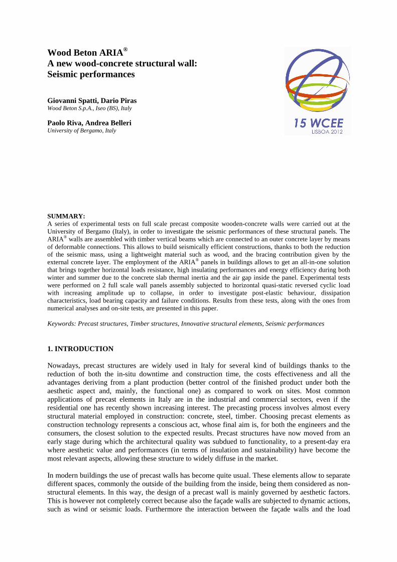
Figure 3. Wood Beton ARIA® typical stratigraphy. 3. EXPERIMENTAL PROGRAM AND NUMERICAL SIMULATIONS 3.1. Test setup The experimental campaign concerned the test of one assembly made by two full scale precast mixed wood-concrete walls subjected to quasi static reversed cyclic loading; the testing of two panels was necessary to avoid torsional effects. The panels were coupled by a timber slab at the top and connected to a common concrete foundation at the bottom by means of the previously proposed connections (Figure 2); the external concrete layer of the panel was intentionally made independent from the foundation by saw-cutting. The specimens were 343.5cm wide, 235cm high and 35cm thick, as reported in Figures 6 and 7. Each panel is composed by timber vertical columns (4 per panel, 10x30cm cross section, GL24c), horizontal beams (6 per panel, 6x23cm, GL24c) and an external C40 concrete slab, 5cm thick with a welded wire mesh Φ5/20/20cm. The connection between timber beams and concrete slab is realized by means of Φ16mm steel lag bolts (Cl. 4.6), paced at 40cm centre to centre. A vertical load of 100kN simulating gravity was applied to each panel. A cyclic horizontal displacement was then imposed at the top of the panels (at 2.0m height) by means of a 1000kN electromechanical screw jack having a 500mm maximum stroke. The screw jack was connected to a reinforced concrete post tensioned reaction wall. The test setup and the applied displacement history are shown in Figure 4 and 5 respectively. The horizontal load, displacements and relative movements between the panels and the foundations were recorded by a load cell and by a series of displacements transducers respectively. A map of the layout of the displacement transducers is shown in Figure 6 and 7.
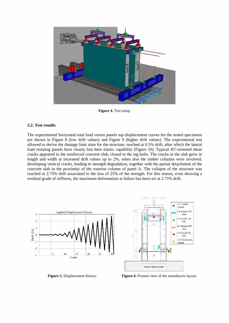
Figure 4. Test setup. 3.2. Test results The experimental horizontal total load versus panels top displacement curves for the tested specimens are shown in Figure 8 (low drift values) and Figure 9 (higher drift values). The experimental test allowed to derive the damage limit state for the structure, reached at 0.5% drift, after which the lateral load resisting panels have clearly lost their elastic capability (Figure 10). Typical 45°-oriented shear cracks appeared in the reinforced concrete slab, closed to the lag bolts. The cracks in the slab grew in length and width at increased drift values up to 2%, when also the timber columns were involved, developing vertical cracks, leading to strength degradation, together with the partial detachment of the concrete slab in the proximity of the exterior column of panel A. The collapse of the structure was reached at 2.75% drift associated to the loss of 25% of the strength. For this reason, even showing a residual grade of stiffness, the maximum deformation at failure has been set at 2.75% drift.
Figure 5. Displacement history. Figure 6. Frontal view of the transducers layout.

Figure 7. Lateral view of the transducers layout.
Figure 8. Force – Displacement graph at low drift values.
Figure 9. Force – Displacement graph at high drift values.

Figure 10. Cracks pattern development through the test.
3.3. Seismic design considerations derived from experimental tests and application to numerical simulations As previously stated, the deformations for both the serviceability limit state and the ultimate limit state have been deduced from the experimental tests and set to 0.5% and 2.75% drift respectively. The behaviour of the wall panels reveals that the failure mode initially involves cracking and detaching of the concrete slab and subsequently involves cracking in the timber columns, showing a residual stiffness even at high values of drift, which is a suitable quality for seismically-efficient structural elements. The bracing attitude of the external concrete slab has been preserved until high values of deformation due to the deformation capacity of the lag bolts placed inside the timber columns, showing a ductile response towards horizontal loads. The structural behaviour factor “q” has been calculated from the previous graphs. Given an elastic and maximum displacements equal to 12.5mm and 45mm respectively, the resultant structural behaviour factor, under equal displacements approximation, reaches the value of 2.5. This value is quite commonly recognizable in several timber structures (e.g. EC8 reports the same behaviour factor for DCM for hyperstatic portal frames with doweled and bolted joints) and reinforced concrete structures (q = 3 for DCM uncoupled walls systems in EC8). Other useful data retrieved from the experimental tests are the equivalent viscous damping (Jacobsen 1960) and the dissipated energy shown in Figure 11 and Figure 12 respectively. It is worth noting that the equivalent viscous damping is close to 5% for almost every lateral displacement.

Figure 11. Equivalent viscous damping.
Figure 12. Dissipated energy. The derived data shown are precious for the definition of a numerical model for the design of real structures, in order to define elements and connections stiffness and the respective performances. In this way, it has been possible to evaluate the seismic performances of a series of buildings which have been built in last years in seismically vulnerable areas of Italy. In order to compare numerical simulations with a real case scenario, an experimental test, performed by means of a vibrodyne and some accelerometers, has been conducted on a 4-storeys building (total height 14m, area per floor 225m2), which has been completely erected with ARIA® walls and whose seismic behaviour was previously investigated by means of numerical simulations through FEM analyses: response spectrum analyses, in which the floors have been considered as rigid diaphragms due to the presence of a 5cm thick reinforced concrete slab, have been carried out with a behaviour factor q=2.5. The investigated building, whose total weight is about 6800kN, was built in Clusone (PGA=0.082g), Italy, on a soil type C with no topographic amplification factors and it was designed for 50 years of service life in medium ductility class (DCM). For the experimental test, a vibrodyne, able to generate sinusoidal loads with a maximum amplitude of 20kN up to 50Hz with a rate resolution of 1/100Hz, was rigidly connected to the third floor of the building, while four accelerometers were placed at each floor for a total number of 16.

Mode 1: X-transl; Period 0.213s; Participated mass 80.7%
Mode 2: Y-transl; Period 0.130s; Participated mass 75.7% Mode 3: Z-rot; Period 0.121s; Participated mass 80.8%
Figure 13. Modal periods.
A comparison between the modal vibration periods is reported in Table 3.1. This evaluation highlights that the usual numerical modelling method, which takes into account the use of both mono-dimensional (beam) and bi-dimensional (plate) elements as well as elastic spring connections, is in good agreement with the effectively built structure. Also the recorder viscous damping results are comparable to the ones evaluated from the horizontal load test. Table 3.1. Comparison between modal periods from numerical model and recorded periods from vibrodyne test.
Numerical simulation Vibrodyne test
Period: [s] Participated mass:[%] Period: [s] Viscous damping: [%] Mode 1 0.213 80.7 dir. Y 0.220 3.90 Mode 2 0.130 75.7 dir. X 0.120 4.70 Mode 3 0.121 80.8 rot. Z 0.100 4.00
4. CONCLUSIONS The results of an experimental test of two coupled full scale precast mixed wood-concrete walls, called ARIA®, subjected to horizontal quasi static reversed cycling loading were presented. The test allowed to derive the seismic characteristics of the panels, the hysteretic behavior and the failure conditions,

which are associated to deterioration of the reinforced concrete slab at the beginning and to deterioration of the external timber columns for higher lateral displacements. The behavior factor results to be equal to 2.5, which is close to design code values for similar structures. The deflection at serviceability limit state was 0.5% of the panel height, which is in agreement with the prescribed value for non-flexible elements in the Italian building code. The deflection at ultimate limit state, resulting equal to 2.75% of the height, was also determined from the experimental test, as well as the lateral load strength and the panel stiffness at different lateral drifts. Considering the test data, the structure shows a proper grade of ductility and a satisfying residual stiffness, allowing to realize seismically efficient buildings. Other experimental tests, carried out by means of a vibrodyne on a full scale 14m high building in order to investigate the dynamic response of the structure, permitted to validate the numerical models developed on the base of the horizontal loading test, highlighting their correspondence with a real case scenario. It needs to be lastly underlined that, in order to achieve the proper performance levels required by the building codes, experimental tests play, for this kind of structures as well as for every new innovative construction solution, a fundamental role in the correct definition of some of the design criteria
AKCNOWLEDGEMENT The cooperation of Mr. Daniele Di Marco, Eng. Consuelo Beschi, Eng. Luca Ferrario, Eng. Mauro Torquati and Eng. Fabrizio Cornali, in setting up the testing system and carrying out the experimental tests is gratefully acknowledged. REFERENCES EN 1998-1:2004, Eurocode 8, 2004. Design of structure for earthquake resistance, Parte 1: General rules,
seismic actions and rules for buildings. D.M. 14 January 2008, Nuove norme tecniche per le costruzioni. Italian Building Code. Goodno, B. J. and Palsson, H. (1986). Analytical Studies of Building Cladding. Journal of Structural
Engineering, 112:4, 665-676. Englekirk, R.E. (1989). Towards a more effective use of precast concrete cladding. Proc. Architectural Precast
Concrete Cladding – Its Contribution to Lateral Resistance of Buildings, PCI, Chicago, USA, pp 4-13. Henry, R. M. and Roll, F. (1986). Cladding-Frame Interaction, Journal of Structural Engineering. Journal of
Structural Engineering, 112:4, 815-834.