wld 204 non destructive testing i visual testing
TRANSCRIPT

NSF-ATE Project Advanced Materials Joining for Tomorrow’s Manufacturing Workforce
WLD 204 Non Destructive Testing I
Visual Testing

NSF-ATE Project 1 Advanced Materials Joining for Tomorrow’s Manufacturing Workforce
INDEX
Visual Inspection General Information
2-3
Visual Inspection Articles
4-16
Visual Inspection Homework
17-20
Visual Inspection Quizzes
21-23
Visual Inspection Welding Defects
24-42
Visual Inspection ASME Procedure
43-63
Visual Inspection Labs
64-66
Visual Inspection Examination Report Sheet
67
This project was supported, in part, by the
National Science Foundation Opinions expressed are those of the authors And not necessarily those of the Foundation

NSF-ATE Project 2 Advanced Materials Joining for Tomorrow’s Manufacturing Workforce
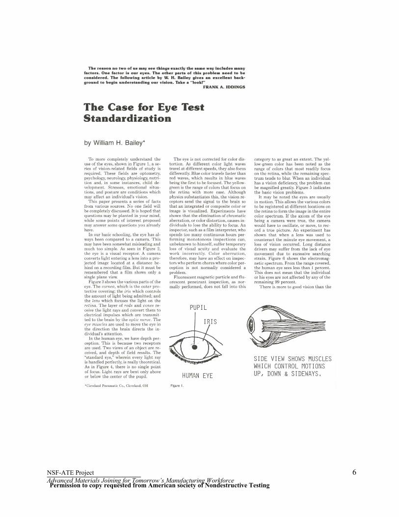
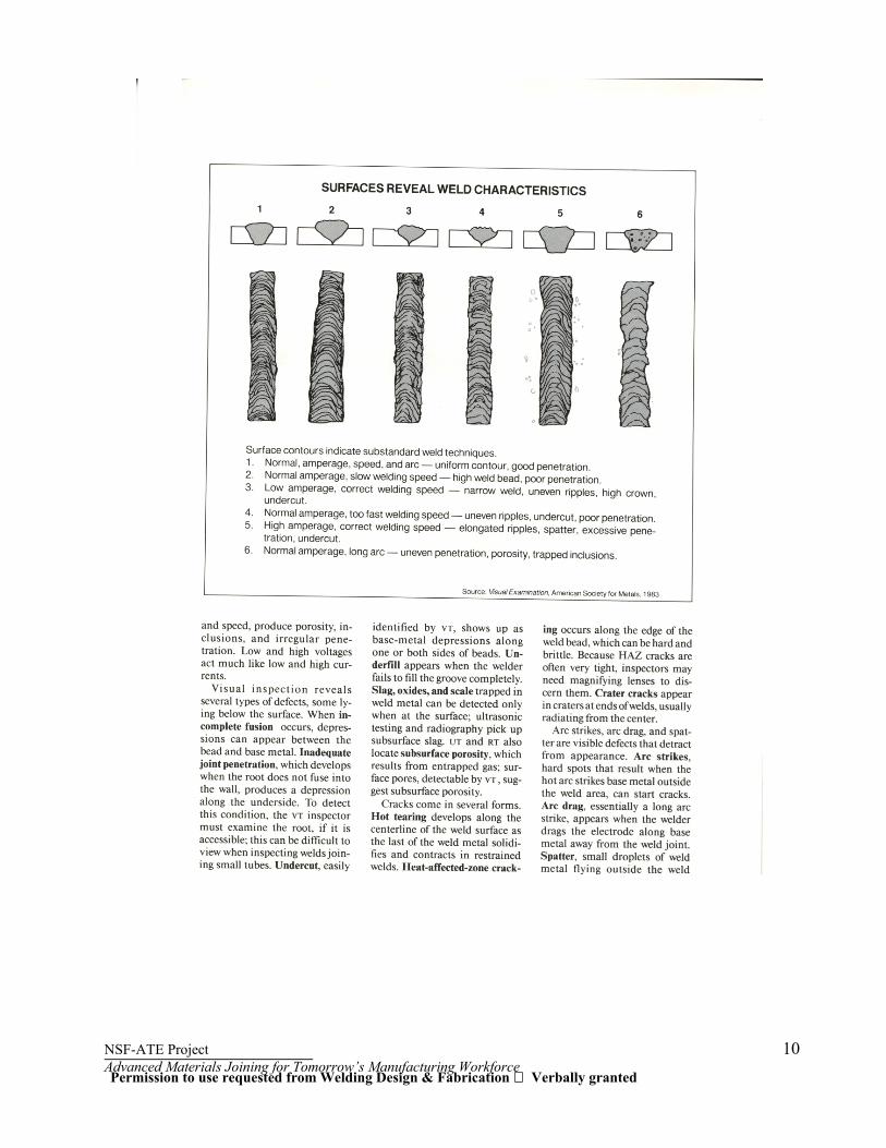
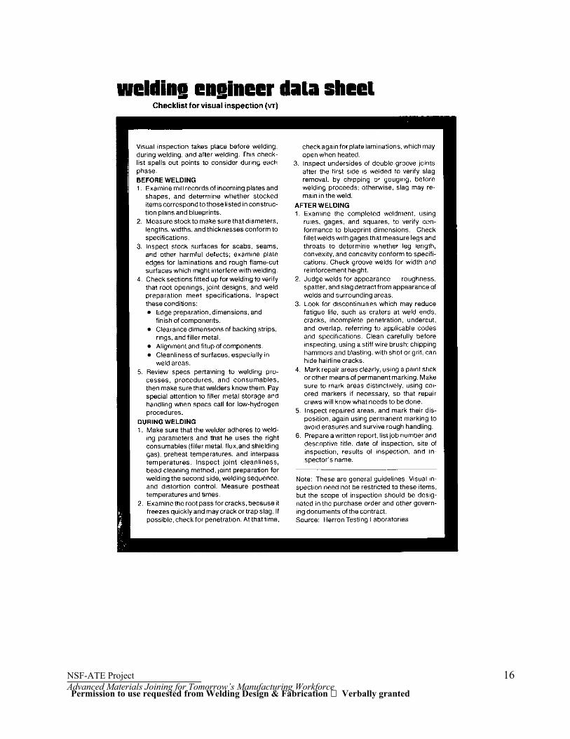
VISUAL INSPECTION (VT) With practice and experience you will learn to uncover a vast amount of information about a weld by visually examining the surface. Such discontinuities as undercut, cracks, surface porosity, inadequate root penetration, and improper dimensions, improper joint prep, improper fit-up or profiles can easily be seen with the eye. Even such things as improper technique by the welder can be detected by studying the weld with a trained eye. We will talk more about the trained eye after showing some advantages and limitations of visual inspection. The Trained Eye (See Article The Case for Eye Test Standardization by William H. Bailey) A person with a trained eye is someone who has really learned to see detail. At first, most of us assume that is an easily acquired skill and say, "I can see all right. Nobody needs to tell me how to see." But as you work with a skillful inspector, you might find yourself saying, "I really didn't see that before. I didn't know that you could tell so much about a weld just by looking at it." A prerequisite to visual inspection is an eye examination and correction of vision (glasses) if necessary. You might call this examination the calibration of your eye. It merely verifies that you can see with a given sensitivity. The next step in visual examination is learning what discontinuities are possible to detect visually, and learning where these will normally show up. For example, undercut occurs along the toe of the bead. It is seen as a groove alongside the weld that may be caused by the amperage being too high or other improper welding techniques. The third aspect of visual inspection is realizing that you cannot see everything with the naked eye, let alone find the smaller discontinuities. There are many devices you can use to help see them. The other methods of nondestructive testing we will talk about are extensions of the eyes. They help in locating and seeing smaller and less distinct discontinuities Once the weld is completed, the acceptance inspection for discontinuities, dimensional accuracy (including distortion), conformity to drawings, and weld appearance (roughness, spatter, etc.) should take place. The thoroughness of this review should be aided by using the other nondestructive inspection methods, as dictated by your judgment or as called for in the specification documents. Improper fit-up undercut, surface porosity, cracks open to the surface, bead contour, and overlap are some typical discontinuities that can be seen with the naked eye. Note that visual inspection, besides being the least expensive of the nondestructive methods, may result in the greatest cost savings. Visual inspection before and during deposition of any weld metal may substantially reduce the overall cost of fabrication. For instance, ultrasonic testing of a weld joint with a borderline indication due to lack of back gouging is very slow and expensive. This ability to eliminate many discontinuities before the weld is completed is perhaps the most important feature of visual inspection.
NSF-ATE Project 3 Advanced Materials Joining for Tomorrow’s Manufacturing Workforce
Advantages 1. Visual inspection is used before, during, and after fabrication of any weldment. 2. Visual inspection will show most large discontinuities and will generally point to other discontinuities
that must be detected by another method. 3. Visual inspection can detect and aid in eliminating discontinuities that might become defects in the
completed weldment. 4. Visual inspection costs less than any other nondestructive inspection method. Limitations 1. The value of visual inspection depends largely on the experience and welding knowledge of the inspector. The inspector should be familiar with design and weld requirements. 2. Visual inspection is limited to detection of surface discontinuities. 3. Visual inspection started too late in the sequence of welding operations cannot detect improper joint fit-up or other costly deviations from best welding practice.

NSF-ATE Project 4 Advanced Materials Joining for Tomorrow’s Manufacturing Workforce
Permission to copy requested from American Society of Nondestructive Testing
NSF-ATE Project 5 Advanced Materials Joining for Tomorrow’s Manufacturing Workforce
Permission to copy requested from American Society of Nondestructive Testing
NSF-ATE Project 6 Advanced Materials Joining for Tomorrow’s Manufacturing Workforce
Permission to copy requested from American society of Nondestructive Testing

NSF-ATE Project 7 Advanced Materials Joining for Tomorrow’s Manufacturing Workforce
Permission to copy requested from American Society of Nondestructive Testing

NSF-ATE Project 8 Advanced Materials Joining for Tomorrow’s Manufacturing Workforce
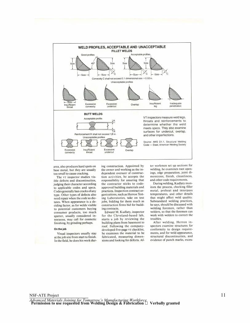
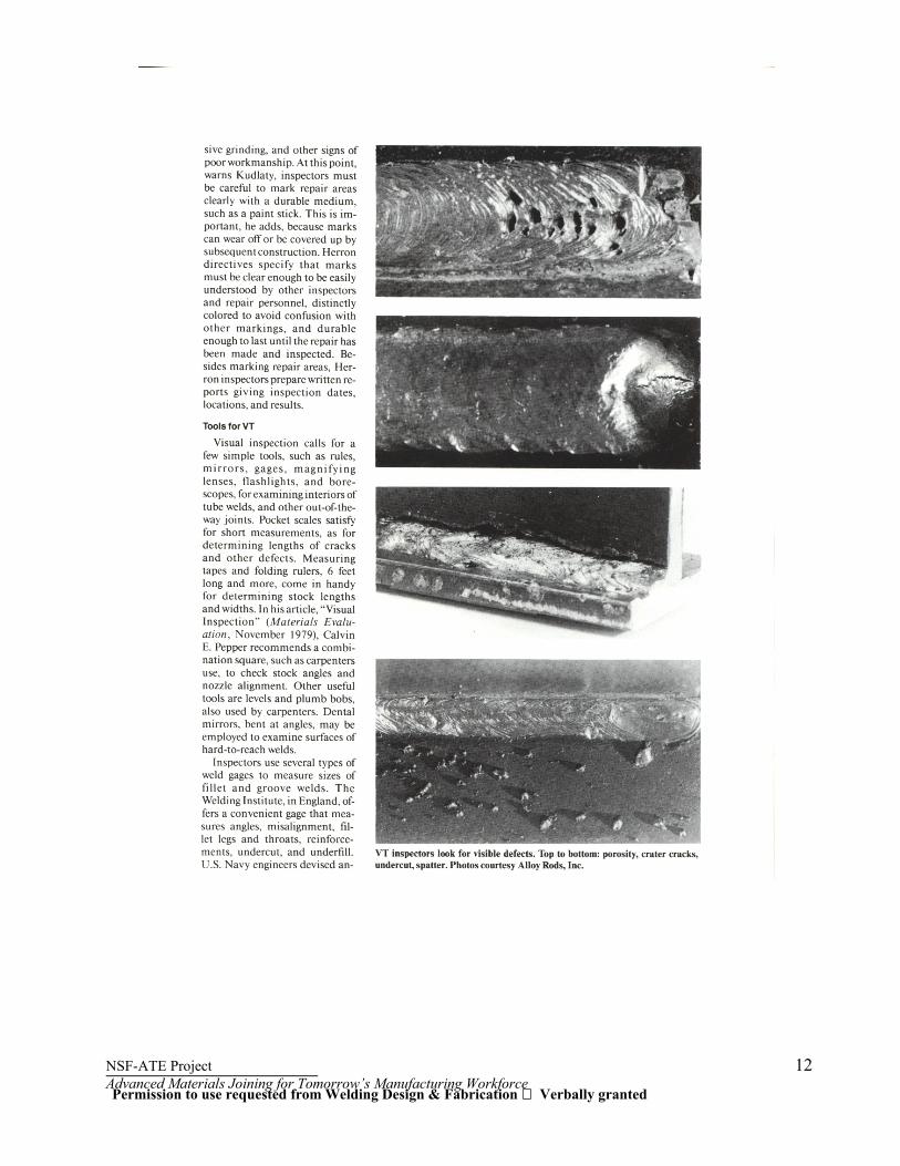
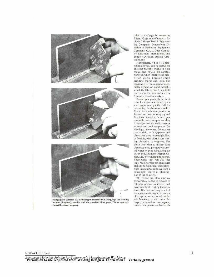
Permission to use requested from Welding Design & Fabrication Verbally granted

NSF-ATE Project 9 Advanced Materials Joining for Tomorrow’s Manufacturing Workforce
Permission to use requested from Welding Design & Fabrication Verbally granted
NSF-ATE Project 10 Advanced Materials Joining for Tomorrow’s Manufacturing Workforce
Permission to use requested from Welding Design & Fabrication Verbally granted
NSF-ATE Project 11 Advanced Materials Joining for Tomorrow’s Manufacturing Workforce
Permission to use requested from Welding Design & Fabrication Verbally granted
NSF-ATE Project 12 Advanced Materials Joining for Tomorrow’s Manufacturing Workforce
Permission to use requested from Welding Design & Fabrication Verbally granted
NSF-ATE Project 13 Advanced Materials Joining for Tomorrow’s Manufacturing Workforce
Permission to use requested from Welding Design & Fabrication Verbally granted

NSF-ATE Project 14 Advanced Materials Joining for Tomorrow’s Manufacturing Workforce
Permission to use requested from Welding Design & Fabrication Verbally granted
NSF-ATE Project 15 Advanced Materials Joining for Tomorrow’s Manufacturing Workforce
Permission to use requested from Welding Design & Fabrication Verbally granted
NSF-ATE Project 16 Advanced Materials Joining for Tomorrow’s Manufacturing Workforce
Permission to use requested from Welding Design & Fabrication Verbally granted

NSF-ATE Project 17 Advanced Materials Joining for Tomorrow’s Manufacturing Workforce
VT HW 1 Name: ______________________ 1. What is the most extensively used Nondestructive Testing Method (NDT)?
A. Radiographic Testing (RT) B. Ultrasonic Testing (UT) C. Visual Testing (VT) D. General Testing
2. Which of the following is not a feature of Visual Inspection?
A. requires no special equipment B. very time consuming C. inexpensive D. requires good eyesight
3. Because visual inspection is the simplest of the NDT methods definite procedures are not
required only common sense and the possession of the proper code book are necessary
A. True B. False
4. Using Visual examination how can plate laminations be observed?
A. using Ultrasonic Inspection B. using a lamination gauge C. by inspecting a cut edge D. A and B
5. After a part has been fit up and is in position to be welded, the visual inspector should inspect the
following to assure the quality of the welded joint. (select more than one)
A. root opening B. edge preparation C. weld metal tensile strength D. density of the base metal
6. Because of the large number of variables that can cause defects, which weld layer or pass is
considered the most important?
A. root pass B. hot pass C. fill pass D. cap pass
NSF-ATE Project 18 Advanced Materials Joining for Tomorrow’s Manufacturing Workforce
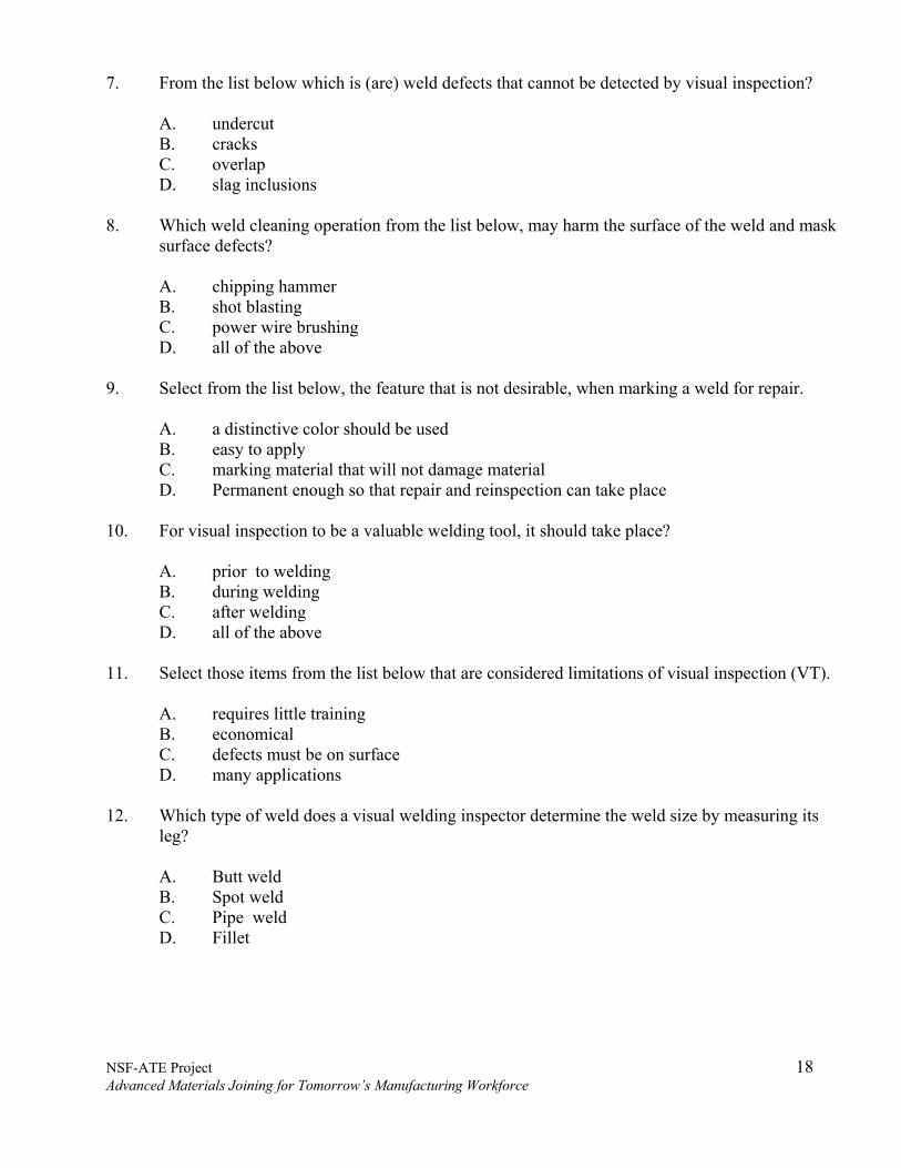
7. From the list below which is (are) weld defects that cannot be detected by visual inspection?
A. undercut B. cracks C. overlap D. slag inclusions
8. Which weld cleaning operation from the list below, may harm the surface of the weld and mask
surface defects?
A. chipping hammer B. shot blasting C. power wire brushing D. all of the above
9. Select from the list below, the feature that is not desirable, when marking a weld for repair.
A. a distinctive color should be used B. easy to apply C. marking material that will not damage material D. Permanent enough so that repair and reinspection can take place
10. For visual inspection to be a valuable welding tool, it should take place?
A. prior to welding B. during welding C. after welding D. all of the above
11. Select those items from the list below that are considered limitations of visual inspection (VT).
A. requires little training B. economical C. defects must be on surface D. many applications
12. Which type of weld does a visual welding inspector determine the weld size by measuring its
leg?
A. Butt weld B. Spot weld C. Pipe weld D. Fillet
NSF-ATE Project 19 Advanced Materials Joining for Tomorrow’s Manufacturing Workforce
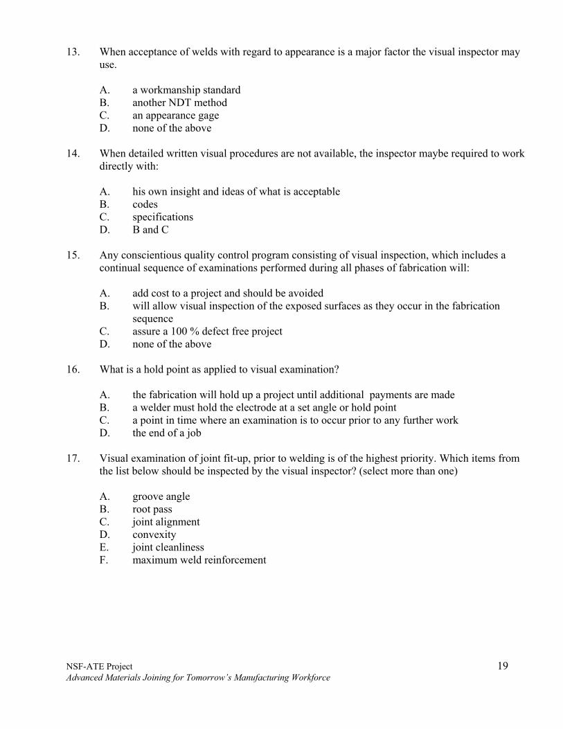
13. When acceptance of welds with regard to appearance is a major factor the visual inspector may
use.
A. a workmanship standard B. another NDT method C. an appearance gage D. none of the above
14. When detailed written visual procedures are not available, the inspector maybe required to work
directly with:
A. his own insight and ideas of what is acceptable B. codes C. specifications D. B and C
15. Any conscientious quality control program consisting of visual inspection, which includes a
continual sequence of examinations performed during all phases of fabrication will:
A. add cost to a project and should be avoided B. will allow visual inspection of the exposed surfaces as they occur in the fabrication
sequence C. assure a 100 % defect free project D. none of the above
16. What is a hold point as applied to visual examination?
A. the fabrication will hold up a project until additional payments are made B. a welder must hold the electrode at a set angle or hold point C. a point in time where an examination is to occur prior to any further work D. the end of a job
17. Visual examination of joint fit-up, prior to welding is of the highest priority. Which items from
the list below should be inspected by the visual inspector? (select more than one)
A. groove angle B. root pass C. joint alignment D. convexity E. joint cleanliness F. maximum weld reinforcement

NSF-ATE Project 20 Advanced Materials Joining for Tomorrow’s Manufacturing Workforce
18. From the list below select the items that a visual welding inspector would perform during
welding that require the aid of a special tool.
A. quality of root B. sequence of weld passes C. cleaning between passes D. interpass temperature
19. What type of weld defect can be avoided with adequate cleaning between weld passes?
A. slag inclusions B. overlap C. incomplete joint penetration D. cracks
20. The type of weld discontinuities, which can be detected by visual examination and are almost
never allowable when the structure is subject to cyclic or fatigue loading are?
A. overlaps B. cracks C. slag inclusions D. porosity

NSF-ATE Project 21 Advanced Materials Joining for Tomorrow’s Manufacturing Workforce
VT QUIZ 1 Name: ___________________
1. Visual inspection is a method of ____________________________________.
2. Nondestructive testing does not destroy or impair the usefulness of the materials being tested.
A. True B. False 3. Inherent discontinuities occur during _________________________________.
4. Lamination occur in bar stock.
A. True B. False
5. Welding pipe and tubing is formed by drawing a flat strip of metal through a __________
__________ or sets of ______________.
6. Weld metal in excess of the quantity require to fill the joint is called the __________ ______________.
7. The heat affected zone is the area of the base metal which has been melted.
A. True B. False
8. Dirt or moisture on the surface of the base metal or contaminated welding consumables can cause ______________.
9. Undercut, under fill and overlap are easily detected by ____________ inspection.
10. Arc strikes may require removal by grinding and inspection by ___________ ____________
_______________.
11. Arc welding requires a protective atmosphere to protect the weld from ___________ ___________.
12. Inclusions are classed as ___________ and _______________.
13. Rule or scale accuracy is limited to
a. .015 b. .001 c. .0015 d. .005

NSF-ATE Project 22 Advanced Materials Joining for Tomorrow’s Manufacturing Workforce
14. Protractors are used to measure a. thickness of steel plate b. thread pitch c. depth of holes and recesses d. angular relationships
15. Weld inspection gages measure
a. weld preparation angles b. height of weld metal c. length of weld d. a and b above
16. The accuracy of a venire micrometer is
a. .001 b. .0001 c. .005 d. .010
17. Consistent accuracy is dependent on the
a. strength of the inspector b. sense of sight c. sense of feel d. both b and c
18. The numbered lines on the micrometer barrel or sleeve represents
a. .100, .200, .300 b. .001, .002, .003 c. .01, .02, .03 d. 1000, 2000, 3000
19. Telescoping gages measure
a. outside diameter b. surface finish c. inside diameters d. fillets and radii
20. The weld gage will measure
a. Undercut b. Filler metal type c. Weld metal temperature d. Area of heat affected zone

NSF-ATE Project 23 Advanced Materials Joining for Tomorrow’s Manufacturing Workforce
21. A visual inspector’s most valuable asset is ___________ ___________.
22. Illumination intensity is measured in ____________ _______________.
23. Flashlights and extension-drop lights provide _____________ ____________.
24. Power of a magnifier is designated by the letter _________________.
25. The flexible bore scope operates entirely with ____________ ____________.

NSF-ATE Project 24 Advanced Materials Joining for Tomorrow’s Manufacturing Workforce
WELDING DEFECTS
A listing and description of defects important to weld quality is presented, with notes on appearance, cause, and effect, emphasizing radiographic appearance and interpretation from radiographic film. Although radiography is emphasized, the appearance of defects and the quality evaluation inspectors understanding of appearance and causes is important for all methods of nondestructive examination Various illustrations of weld defects are included.
NSF-ATE Project 25 Advanced Materials Joining for Tomorrow’s Manufacturing Workforce
A – WELDING DEFECTS
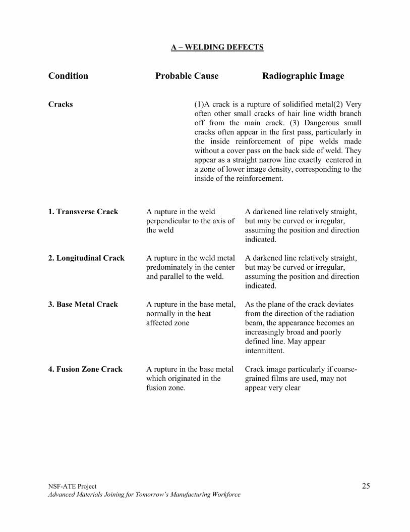
Condition Probable Cause Radiographic Image Cracks (1)A crack is a rupture of solidified metal(2) Very
often other small cracks of hair line width branch off from the main crack. (3) Dangerous small cracks often appear in the first pass, particularly in the inside reinforcement of pipe welds made without a cover pass on the back side of weld. They appear as a straight narrow line exactly centered in a zone of lower image density, corresponding to the inside of the reinforcement.
1. Transverse Crack A rupture in the weld perpendicular to the axis of the weld
A darkened line relatively straight, but may be curved or irregular, assuming the position and direction indicated.
2. Longitudinal Crack A rupture in the weld metal predominately in the center and parallel to the weld.
A darkened line relatively straight, but may be curved or irregular, assuming the position and direction indicated.
3. Base Metal Crack A rupture in the base metal, normally in the heat affected zone
As the plane of the crack deviates from the direction of the radiation beam, the appearance becomes an increasingly broad and poorly defined line. May appear intermittent.
4. Fusion Zone Crack A rupture in the base metal which originated in the fusion zone.
Crack image particularly if coarse-grained films are used, may not appear very clear

NSF-ATE Project 26 Advanced Materials Joining for Tomorrow’s Manufacturing Workforce
5. Crater Crack Occurs occasionally when the
welding is interrupted improperly.
A fine irregular or star shaped darkened area cracks criss-cross and proceed only to the edge of the crater.
6. Incomplete Penetration (lack of )
Occurs at the root of welds designed for through penetration where full penetration has not been achieved - weld metal failing to fuse to the base metal.
That may be either continuous or intermittent in center of weld (butt) edge of weld (fillet) The indication may be thin and sharp, broad and diffused or two parallel lines, depending upon the specific geometry of the joint and the width of the discontinuity.
7. Incomplete Fusion (lack of )
Caused by molten weld metal, which has failed to bond to the base metal or to a previously deposited weld bead.
Dark indications usually elongated and varying in length and width. May be intermittent or continuous.
8. Porosity (Gas Pockets)
Occurs as voids caused by gas trapped in the weld deposit. Gas pockets are not peculiar to any one spot in the weld and may be fairly well scattered.
Spherical voids have the appearance of a rounded dark area while the non-spherical voids have an elongated dark area with smooth outline. Can be scattered fine or coarse, clustered, elongated, linear or worm hole(pipe).

NSF-ATE Project 27 Advanced Materials Joining for Tomorrow’s Manufacturing Workforce
9. Slag Inclusions Particles of slag entrapped in
the weld metal or along the fusion planes. Due to their low specific gravity, these compounds tend to seek the upper surface of the molten metal. The distance of the slag line from the center of the weld can indicate the probable depth of the slag area if the angle of the bevel is known.
Isolated slag deposits usually form an irregular body and are most frequently found at the edge or fusion line of the particular bead. The most frequent type of slag deposits are found between the first or root pass and the second pass. Such slag deposits may be quite long and appear as lines of some width. Where such lines are found on both sides of the root bead, they are commonly referred to as ”wagon tracks”. These frequently have considerable length but seldom are of excessive width. Isolated slag pockets on the other hand frequently have decided width as well as length. Generally the density of a slag inclusion is rather uniform throughout.
10. Burn through Melting of the metal from the root of the weld or through the backing strip. This discontinuity occurs in seams welded from one side only.
Darkened area of elongated or rounded contour, which may be surrounded by a lighter ring. Where such an area is indicated merely by a circle, the second pass has filled the original defect. Frequently, an area will appear only slightly darker than the weld density, but will contain a very black line in the center. This indicates that the second pass filled the original hole in the root pass, but that a shrinkage crack has developed at this point. Such shrinkage cracks may extend entirely through the second pass.

NSF-ATE Project 28 Advanced Materials Joining for Tomorrow’s Manufacturing Workforce
11. Undercut Longitudinal groove melted
into the base metal adjacent to the toe of the weld. Another type of undercut may occur in backing strip joints where the backing strip is left in place. It is caused by melting away of the base metal at the root. This type is generally termed root undercut.
Dark linear indication of indistinct outline adjacent to the edge of the weld. Root undercut - appears as a relatively straight and narrow dark line and can be located on either one or both sides of the root opening location.
12. Icicles (Teardrops)
Fused droplets of weld metal extending beyond the root of the weld, occurring in seams welded from one side only.
Rounded lighter indications with an occasional small dark spot in the center of the drop.
13. Tungsten Inclusions Tungsten particles entrapped in the weld deposits considered local stress risers.
Lighter than surrounding areas and may be rounded or irregular. Can be in clusters or rectangles.

NSF-ATE Project 29 Advanced Materials Joining for Tomorrow’s Manufacturing Workforce
WELDING DEFECTS (Surface)
Condition Probable Cause Radiographic Image 1. Incompletely Filled Weld Grooves
Insufficient deposit of weld metal to fill groove to edge of base metal.
This lack of material is imaged by increased density in the corresponding areas.
2. Concavity at the Weld Root
A concave surface at the root of the weld; occurs particularly in pipe welding without cover pass on the root side.
Consists of a dark line in the center of the weld. It cannot be mistaken for lack of penetration, since the line is broader and lacks sharp boundaries.
3. Excessive Reinforcement If a weld is made with an excessive number of passes or with inadequate arc current or the speed of travel in submerged arc welding is too slow, the weld reinforcement will be too convex and too high.
Because of the abrupt change in thickness at the boundary between the base metal and the reinforcement, the image will show lowered density at the edge of the reinforcement adjacent to the base metal.
4. Overlap If an excess of metal is deposited in the final pass, or if inadequate current or speed of travel is used in submerged arc welds, the deposited metal may overlap the base metal, causing lack of fusion at the edges of the reinforcement.
This peculiar profile is indicated by an abrupt change in density between the parent metal and the reinforcement. The edge of the reinforcement characteristically shows an irregular waviness often containing gas inclusions.

NSF-ATE Project 30 Advanced Materials Joining for Tomorrow’s Manufacturing Workforce
5. Excessive Penetration Molten metal runs through the
root of the weld groove, producing an excessive reinforcement at the backside of the weld. In general, this condition is not continuous but has an irregular shape with characteristic hanging drops of excessive metal (teardrops)
A line of lowered density in the center of the weld; irregularities in the shape are accompanied by corresponding irregularities in density. Round white spots in the center of the weld corresponds to hanging drops of metal. These often contain blow holes
6. Longitudinal grooves In horizontal, multiple pass welds, the last pass may fail to form a smooth top surface. Instead, longitudinal grooves may appear in the surface of the deposited metal, paralleling the weld bead.
These thickness variations produce dark lines corresponding to the reduced metal thickness at the grooves. Their diffused edges cannot be mistaken for images of slag lines, which are sharper and thinner. In addition, the dark lines corresponding to the grooves are rarely exactly straight.
7. Undercutting The exposed upper edges of the beveled weld preparation tend to melt and run down into the deposited metal, resulting in a groove, which may be either with more or less sharp edges paralleling the weld reinforcement.
A dark line of varying width and extent, readily seen between the lower image density zones corresponding to the reinforced base metal.

NSF-ATE Project 31 Advanced Materials Joining for Tomorrow’s Manufacturing Workforce
8. Out of Line weld Beads Insufficient care in
positioning automatic welding machines, or careless chipping out of the backside of single-vee welds so that the groove is displaced from the root of the weld, this leads to misalignment of the two weld beads.
Because of the added thickness of the reinforcements, misalignment is evident by the displacements from the centerline of the images of the two weld reinforcements. In the case of the single-vee weld preparations, misalignment is clearly seen. The width of the root reinforcement is much less than that of the cover pass reinforcement, so its image appears clearly and can be discriminated from the image of the front surface reinforcement.
9. Irregularities at Start and Stops
A reduction in reinforcement thickness can result at the end of the bead laid by the first electrode, followed by an increase thickness at the point where the new electrode was started.
Shows a crescent shaped indication with lower density followed by higher image density as the reinforcement returns to normal thickness in the direction of travel. Sometimes, small slag inclusions occur at the point of electrode change.
10. Grinding Marks When weld reinforcements are not ground out smoothly, the resultant thickness varies above and below that of the base metal.
Show variously shaped areas of uneven image densities usually with sharp contours. Such indications from the grinding wheel are recorded just like surface tool marks of any kind.
11. Spatter of Weld Metal Droplets of molten metal splattered about the weld region. These drops stick to the surface of the metal near the weld seam.
Since they correspond to local areas of increased thickness, their radiographic images consist of light round spots.

NSF-ATE Project 32 Advanced Materials Joining for Tomorrow’s Manufacturing Workforce
12. Arc Strikes Arc-Starting Marks
(Spitting)
When the welding arc is started or displaced during welding out onto the base metal surface beside the weld groove, an irregular deposit of filler metal occurs on the base metal near the weld seam. In some cases this deposit is accompanied by an indentation due to melting of the base metal where the arc was struck.
Consists of a lowered density spot corresponding to the irregular shape of the deposited metal, often accompanied by an irregular dark spot where the arc has melted into the base metal.

NSF-ATE Project 33 Advanced Materials Joining for Tomorrow’s Manufacturing Workforce
High-low is defined as a condition where the pipe and /or fitting surfaces are misaligned.
Inadequate penetration is defined as the incomplete filling of the weld groove with weld metal
A burn-through area is that portion in the root bead where excessive penetration has caused the weld puddle to be blown into the pipe
A slag inclusion is a non-metallic solid entrapped in the weld metal, or between the weld metal and the pipe metal. Elongated slag inclusions are usually found at the fusion zone. Isolated slag inclusions are irregularly shaped inclusions and may be located anywhere in the weld.
Porosity or gas pockets are voids occurring in the weld metal. Maximum distribution of gas pockets is usually determined by code or standard.
Welds containing cracks, regardless of size or position are not normally acceptable

NSF-ATE Project 34 Advanced Materials Joining for Tomorrow’s Manufacturing Workforce
Undercutting is the burning away of the side walls of the welding groove at the edge of a layer of weld metal, or the reduction in the thickness of the pipe wall adjacent to the weld and where it is fused to the surface of the pipe.
The term “internal concavity” as used in the paper shall mean a bead which is properly fused to and completely penetrated the wall thickness along both sides of the bevel, but the center of the bead is somewhat below the inside surface of the pipe wall. The magnitude of the concavity shall be defined as the perpendicular distance between an axial extension of the pipe wall surface and the lowest weld bead surface point.
Incomplete fusion is defined as the lack of bond at the root of the joint or at the top of the joint between base metal and weld metal. Hollow bead is elongated linear porosity occurring in the root pass.

NSF-ATE Project 35 Advanced Materials Joining for Tomorrow’s Manufacturing Workforce
CRACKING The result of localized stress, which at some point exceeds the ultimate strength of the metal. TYPES OF CRACKING FOUND – Longitudinal, Transverse, Crater, Underbead CAUSES PREVENTION A. Releasing lineup equipment to soon. A. Complete stringer or root pass before
releasing lineup equipment. (In some cases two passes may be required.
B. Cold weather. B. Preheat when necessary. Use required number of welders on large pipe.
Once welding is started don’t stop on a stringer bead.
Clean stringer beads at once. Run hot pass as soon as possible. Protect weld from rapid cooling.
C. High carbon pipe. C. Change welding procedure and rod type D. Excessive preheat.
D. Use correct heats.
E. Tack welds not reworked.
E. Use proper procedure for reworking tack
welds. F. Rapid cooling.
F. Follow a proper welding procedure.
G. Insufficient preheating.
G. Follow a proper welding procedure.
H. Initial bead to small.
H. Follow a proper welding procedure
Note: As bead size increases, cracking possibilities also increase, therefore, small or medium size
beads laid in correct sequence and position result in the best type pipeline joint. Where large beads are necessary the joint must be protected from rapid cooling, in some cases stress relieving may be necessary.
NSF-ATE Project 36 Advanced Materials Joining for Tomorrow’s Manufacturing Workforce
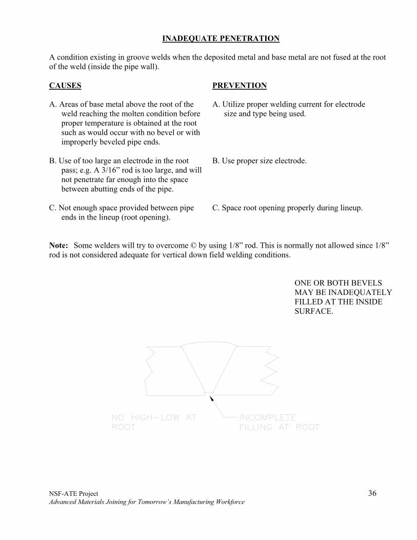
INADEQUATE PENETRATION A condition existing in groove welds when the deposited metal and base metal are not fused at the root of the weld (inside the pipe wall). CAUSES PREVENTION A. Areas of base metal above the root of the
weld reaching the molten condition before proper temperature is obtained at the root such as would occur with no bevel or with improperly beveled pipe ends.
A. Utilize proper welding current for electrode size and type being used.
B. Use of too large an electrode in the root pass; e.g. A 3/16” rod is too large, and will not penetrate far enough into the space between abutting ends of the pipe.
B. Use proper size electrode.
C. Not enough space provided between pipe ends in the lineup (root opening).
C. Space root opening properly during lineup.
Note: Some welders will try to overcome © by using 1/8” rod. This is normally not allowed since 1/8” rod is not considered adequate for vertical down field welding conditions.
ONE OR BOTH BEVELS MAY BE INADEQUATELY FILLED AT THE INSIDE SURFACE.

NSF-ATE Project 37 Advanced Materials Joining for Tomorrow’s Manufacturing Workforce
INADEQUATE PENETRATION DUE TO HIGH LOW INADEQUATE PENETRATION DUE TO HIGH LOW INADEQUATE PENETRATION DUE TO INTERNAL CONCAVITY

NSF-ATE Project 38 Advanced Materials Joining for Tomorrow’s Manufacturing Workforce
BURN THROUGH
Excessive penetration causes weld puddle to be blown into the pipe. CAUSE PREVENTION A. Excessive welding heat. A. Correct current rates. B. Poor electrode manipulation. B. Correct technique. C. Thin stringer bead. C. Correct size rod D. Excessive space in lineup. D. Proper lineup. E. Lamination of pipe wall E. Correction is at the steel mill.
1. Field method for correction- begin cutting at the pipe end, cut longitudinally back until lamination disappears. Make several cuts around periphery of pipe to be certain that metal is good. Rebevel pipe before welding.

NSF-ATE Project 39 Advanced Materials Joining for Tomorrow’s Manufacturing Workforce
INCOMPLETE FUSION Failure to fuse together adjacent layers of weld metals or adjacent weld metal and base metal. CAUSE PREVENTION Failure to raise the temperature of the base metal (Or previously deposited weld metal) to the melting point, or to dissolve, by means of flushing. The oxides or other foreign material present on the surface to which the deposited metal must fuse.
1. Maintain surfaces free from foreign matter. 2. Use proper heat and electrode manipulation. 3. Once a welding pass is started it should be
completed with a minimum of interruption. When starting with a new rod, manipulate arc back into previously deposited weld to insure complete fusion.
INCOMPLETE FUSION AT ROOT OF BEAD OR TOP OF THE JOINT
INCOMPLETE FUSION DUE TO COLD LAP
NSF-ATE Project 40 Advanced Materials Joining for Tomorrow’s Manufacturing Workforce
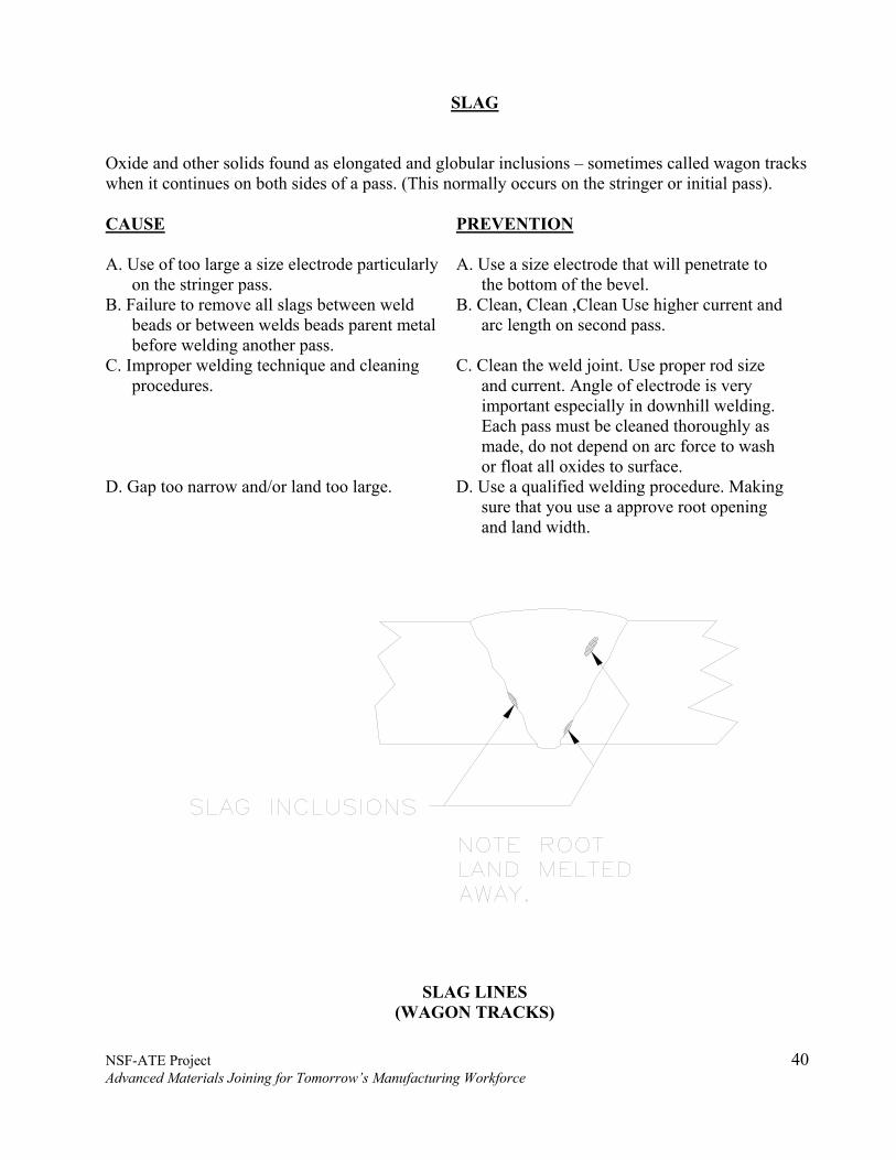
SLAG
Oxide and other solids found as elongated and globular inclusions – sometimes called wagon tracks when it continues on both sides of a pass. (This normally occurs on the stringer or initial pass). CAUSE PREVENTION A. Use of too large a size electrode particularly
on the stringer pass. A. Use a size electrode that will penetrate to
the bottom of the bevel. B. Failure to remove all slags between weld
beads or between welds beads parent metal before welding another pass.
B. Clean, Clean ,Clean Use higher current and arc length on second pass.
C. Improper welding technique and cleaning procedures.
C. Clean the weld joint. Use proper rod size and current. Angle of electrode is very important especially in downhill welding. Each pass must be cleaned thoroughly as made, do not depend on arc force to wash or float all oxides to surface.
D. Gap too narrow and/or land too large. D. Use a qualified welding procedure. Making sure that you use a approve root opening and land width.
SLAG LINES (WAGON TRACKS)

NSF-ATE Project 41 Advanced Materials Joining for Tomorrow’s Manufacturing Workforce
POROSITY A type of globular void free of any solid material also referred to as gas pockets. CAUSES PREVENTION A. Excessive welding heat A. Use recommended amperage for rod being
used. Various coatings require different current rates.
B. Incorrect electrode manipulation. B. Work area must be large enough to permit welder to obtain correct angle between welding rod and the work. Also permitting free movement of the rod.
C. Damp electrodes or high winds. C. Keep rods dry. Do not take out an excessive supply of rods. Use windscreens when necessary. Store electrode at recommended temperature and conditions.
D. Improperly maintained welder. D. Maintain welder and cables according to manufactures recommendations.
E. Excessive travel speed. E. Maintain recommended welding speed.

NSF-ATE Project 42 Advanced Materials Joining for Tomorrow’s Manufacturing Workforce
Porosity (PIN HOLES) on Cover Pass CAUSES PREVENTION A. Electrode too dry or wet. A. Proper electrode storage. B. Poor technique (excessive speed etc.) B. Proper technique C. Cover pass too wide. C. Proper width cover pass D. Rusty or Dirty Material. D. Properly clean material.
UNDERCUTTING
The melting or burning away of base metal. CAUSES PREVENTION A. Excessive welding heat. A. Properly maintain equipment to insure
proper welding parameters. B. Poor technique (arc length too long etc.) B. Proper technique C. Cover pass too wide. C. Proper width cover pass D. Rusty or Dirty Material. D. Properly clean material.
NSF-ATE Project 43 Advanced Materials Joining for Tomorrow’s Manufacturing Workforce
ASME Visual Examination Procedure Examination
VISUAL EXAMINATION

NSF-ATE Project 44 Advanced Materials Joining for Tomorrow’s Manufacturing Workforce
ASME Visual Examination Procedure Examination
TABLE OF CONTENTS 1.0 SCOPE 45
1.1 Requirements 45 2.0 GENERAL 46 3.0 REFERENCES 47 4.0 PERSONNEL 48 5.0 EQUIPMENT 49 6.0 PROCESS 50
6.1 Applications 50 6.2 Direct Visual Examination 50 6.3 Remote Visual Examination 50 6.4 Translucent Visual Examination 51
7.0 PROCEDURE 51 7.1 Time of Examination 51 7.2 Surface Condition 51 7.3 Technique 51 7.4 Lighting 51 7.5 Resolution of Examination 52 7.6 Examination 52 7.7 Record able Data 52 7.8 Examination of Repairs 52
8.0 REPORTS 53 9.0 ACCEPTANCE STANDARDS 54 10.0 FORMS and ILLUSTRATIONS 55
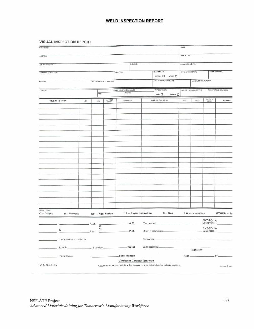
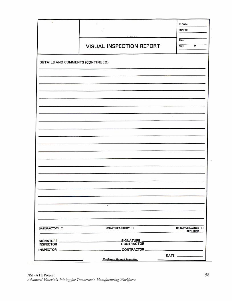
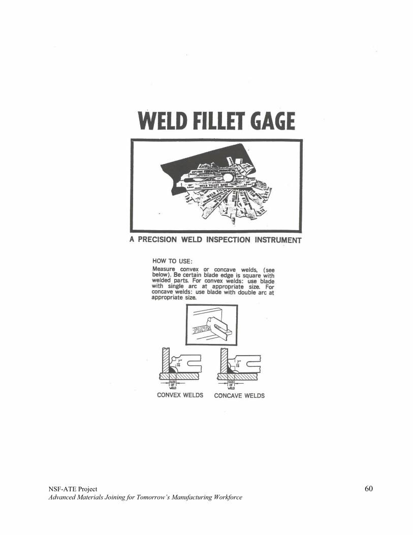
• Visual Inspection Report 56 • Weld Inspection Report 57 • Visual Inspection Report (Detail) 58 • Non-Conformance Report 59 • Weld Fillet Gauge 60 • Typical Wire Gage 61
11.0 DEFINITIONS 62-63
NSF-ATE Project 45 Advanced Materials Joining for Tomorrow’s Manufacturing Workforce
ASME Visual Examination Procedure Examination 1.0 SCOPE
1.1 Requirements
This procedure covers the general requirements for direct and remote examination of materials as may be required by the client's specifications and by various codes under which a component or system is being designed and manufactured.
1.1.1 This procedure is not intended to cover the visual examination involved in
interpretation of other non-destructive examination methods such as radiography, ultrasonic, magnetic particle, liquid penetration, hydrostatic testing, leak testing, or eddy current.
1.1.2 This document meets the minimum requirements of the ASME Code, Section V,
Article 9, and any other code or specification referencing the methods for visual examination as defined by ASME, Section V, Article 9.
1.1.3 This document meets the minimum requirements of API- 1104, Sixteenth Edition,
May 1983, Section 5.0.

NSF-ATE Project 46 Advanced Materials Joining for Tomorrow’s Manufacturing Workforce
ASME Visual Examination Procedure Examination 2.0 GENERAL
2.1 Visual examination as performed to this procedure is direct visual examination or remote
visual examination (using such visual aids as mirrors, bore scopes, cameras, magnifiers, etc.). The effectiveness of the examination primarily depends on the resolution of the examination technique, the expertise of the technician, the visual acuity of the technician, and the acceptance standards.
2.2 In order to perform visual examination of materials to this procedure, it may be necessary
for the client to provide the following information in writing:
a) Identify the material to be examined. This information should include the project or contract designation, the component or piece, mark the area(s) to be examined with respect to location on the component or piece, and the site.
b) How visual examination is to be performed. c) Type of surface condition available. d) Method or tool for surface preparation, if any. e) Whether direct or remote viewing is used. f) Special illumination, instruments, or equipment to be used, if any. g) Sequence of performing examination, when applicable. h) Date to be tabulated, if any. i) Report forms or general statement to be completed. j) The acceptance standards to be used. k) When applicable, the marking system required.

NSF-ATE Project 47 Advanced Materials Joining for Tomorrow’s Manufacturing Workforce
ASME Visual Examination Procedure Examination 3.0 REFERENCES
3.1 The following documents, of the issue in effect as called out on the purchase order or contract, have been referenced in the preparation of this procedure and are considered a part of this procedure as applicable:
• American Society of Mechanical Engineers (ASME)
I Power Boilers V Nondestructive Examination VIII Div. 1 Pressure Vessels VIII Div. 2 Alternate Rules, Pressure Vessels
• American Petroleum Institute (API)
API-1104 Standard for welding pipelines and related facilities. API-650 Welded steel tanks for oil storage. API-653 Tank inspection, repair, alternation, and reconstruction. API-1107 Recommended pipeline maintenance welding practices.
• American Welding Society (AWS) ANSI/AWS D1.1 Structural Welding Code • American Society for Nondestructive Testing (ASNT) SNT-TC-1A Nondestructive testing personnel Qualification and Certification. • PCC Procedures QC-OO1 Procedures for the qualification and certification of nondestructive
examination personnel to SNT-TC-1A and alternative 1.

NSF-ATE Project 48 Advanced Materials Joining for Tomorrow’s Manufacturing Workforce
ASME Visual Examination Procedure Examination 4.0 PERSONNEL
4.1 Personnel performing visual examination to this procedure shall be qualified and certified in accordance with PCC "Procedures for the Qualification and Certification of Nondestructive Examination Personnel to SNT-TC-1A and alternative 1". (Note: SNT-TC-1A has been used as a guide in the preparation of this procedure.)
4.2 Only certified Level II, Level III, or AWS QC-1 personnel shall interpret examination
results to determine acceptability.
4.3 Visual Inspection Personnel - All personnel responsible for conducting in-process and final visual inspections must be familiar with the acceptance standards specified.
4.4 Annual Visual Tests - All personnel responsible for performing visual inspections must
take an annual vision test. If glasses are required for use on the job (Corrected/uncorrected), they must be worn during the vision test. PCC will maintain on file a record of the individual's vision test results.

NSF-ATE Project 49 Advanced Materials Joining for Tomorrow’s Manufacturing Workforce
ASME Visual Examination Procedure Examination 5.0 EQUIPMENT
5.1 Lighting - For direct visual examination, the lighting shall be sufficient to provide for the required examination resolution. Lighting shall be considered sufficient when it is measured by a light meter and is found to be more than 32.5 foot candles at the surfaces to be examined or when a black line 1/32" wide on an 18% neutral gray card can be resolved under the worst conditions of lighting, angles of vision, etc., to be encountered in the examination. (See paragraph 6.2)
5.2 Visual Aids, including mirrors, bore scopes, cameras, remote controls, etc., when used as
an integral part of the examination technique, shall be approved for use by the client and their use shall be noted on the Visual Examination Technique Record. Visual aids not used as an integral part of the examination (such as for verifying interpretation of an indication) need not be approved by the client.
5.3 Weld gages must be used during visual weld inspection. The size and shape of fillet
welds and the amount of reinforcement of butt welds shall be checked by suitable gages.

NSF-ATE Project 50 Advanced Materials Joining for Tomorrow’s Manufacturing Workforce
ASME Visual Examination Procedure Examination 6.0 PROCESS
6.1 Applications
Visual examination is generally used to determine such things as the surface condition of the part, alignment of mating surfaces, shape, or evidence of leaking. In addition, visual examination is used to determine a composite material's (translucent laminate) subsurface conditions.
6.2 Direct Visual Examination
Direct visual examination may usually be made when access is sufficient to place the eye within 24 inches of the surface to be examined and at an angle not less than 30 degrees to the surface to be examined. Mirrors may be used to improve the angle of vision, and aids such as a magnifying lens may be used to assist examinations. The specific part, component, vessel, or election thereof, under immediate examination, shall be illuminated, if necessary with flashlight or other auxiliary lighting, to attain a minimum of 15 fc for general examination and a minimum of 50 fc for the detection or study of small anomalies. Visual examination to assure natural or corrected near distance acuity such that they are capable of reading standard J- 1 letters on standard Jaeger test type charts for near vision or equivalent methods.
6.3 Remote Visual Examination
In some cases, remote visual examination may have to be substituted for direct examination. Remote visual examination may use visual aids such as mirrors, telescopes, bore scopes, fiber optics, cameras, or other suitable instruments. Such systems shall have a resolution capability at least equivalent to that obtainable by direct visual observation.
6.4 Translucent Visual Examination
Translucent visual examination is a supplement of direct visual examination. The method of translucent visual examination uses the aid of artificial lighting, which can be contained in an illuminator that produces directional lighting. The illuminator shall provide light of an intensity that will illuminate and diffuse the light evenly through the area or region under examination. The ambient lighting must be so arranged that there are no surface glares or reflections from the surface applied through the area or region under examination. The artificial light source shall have sufficient intensity to permit "candling" any translucent laminate thickness variation. Classification of the visual imperfections shall be made as recommended in SD-2563, Article 28.

NSF-ATE Project 51 Advanced Materials Joining for Tomorrow’s Manufacturing Workforce
ASME Visual Examination Procedure Examination 7.0 PROCEDURE
7.1 Time of Examination
The areas to be examined and the time of examination shall be specified by the client.
7.2 Surface Condition
The areas to be examined shall be free of oil, grease, dirt, lint, and other contaminants that might mask a discontinuity.
7.3 Technique
For a specific examination, the technique variables shall be recorded on a Visual Examination Technique Record. This technique record will be used to identify and repeat examination variables. A copy of the Visual Examination Technique Record shall be furnished with reports.
7.3.1 The following information shall appear on the Visual Examination
Technique Record:
a) Identification of materials under examination and specification and acceptance standards to which the examination is to be made.
b) Whether the examination is to be made by direct visual examination or by remote visual examination.
c) Equipment to be used during the examination such as additional lighting, mirrors, bore scope, cameras, magnifiers, etc.
d) Instructions for showing location of unacceptable discontinuities on the report.
e) A checklist of indications, dimensions, or conditions to be recorded.
f) When direct examination is used, the maximum distance from the eye to the examination surface shall be 24 inches and the minimum angle between the eye and the examination surface shall be 30º, unless otherwise approved by the client.
g) Adequacy of the examination resolution.
7.4 Lighting Lighting shall meet the requirements of Paragraphs 5.1 and 6.2.

NSF-ATE Project 52 Advanced Materials Joining for Tomorrow’s Manufacturing Workforce
ASME Visual Examination Procedure Examination
7.5 Resolution of Examination
The resolution of the examinations shall be considered adequate when a black line 1/32" wide on an 18% neutral gray card can be resolved under the worst conditions of lighting, angles of visions, etc., to be encountered in the examination. The resolution may be proven at the time of the examination or may have been proven at a previous time for an examination having the same technique variables. Adequacy of resolution shall be documented on the technique record.
7.6 Examination The required examinations shall be made in accordance with the Visual Examination Technique Record and a checklist for each specific examination. The checklist should be approved by the client.
7.6.1 Workmanship - Workmanship shall be in accordance with good commercial practices.
7.6.2 Dimensions and Tolerances - Parts shall be inspected for conformance
with dimensions and tolerances specified on the drawings. Any dimensions falling outside the specified limits shall be cause for rejection.
7.7 Record able Data
Indications, dimensions, or conditions as listed in the checklist shall be recorded.
7.8 Examination of Repairs
Shall be done using the same procedure and technique used to detect and evaluate the discontinuities.

NSF-ATE Project 53 Advanced Materials Joining for Tomorrow’s Manufacturing Workforce
ASME Visual Examination Procedure Examination 8.0 REPORTS
8.1 Checklist
An examination checklist shall be used to plan visual examination and to verify that the required visual observations were performed. This checklist establishes minimum examination and inspection requirements and does not indicate the maximum examination, which the Manufacturer may perform in process.
8.2 Visual Examination Report
A visual examination report shall be prepared and furnished to the client. A standard visual examination report form will be used unless otherwise requested by the client.
8.2.1 The report shall contain the following:
• Name of the company and the visual examination, procedure number,
technician, level of certification, the contract number, job number, and date of the visual examination.
• The illuminators, instruments, equipment, tools, etc., shall be identified in
the report to the extent that they or their equivalents can be obtained for future examination. This may be accomplished by referencing the visual examination procedure number.
• At the option of the Manufacturer, he may maintain one certification for
each product, or several separate signed records based on the area or type of work, or both combined. Where impractical to use specialized visual examination personnel, knowledgeable production workmen may be used to perform the examination and to sign the report forms.
• Even though dimensions, etc., were recorded in the process of visual
examination to aid in the evaluation, there need not be documentation of each viewing or each dimensional check. Documentation shall include all observation dimensional checks specified by the referencing Code Section.
• A drawing or sketch identifying and showing the location of the area
examined and the item or piece number.
• Examination variables to permit repetition of the examination at a later date.
8.2.2 The required number of report copies will be furnished to the client.
• A minimum of one report copy will be kept on file at the PCC

NSF-ATE Project 54 Advanced Materials Joining for Tomorrow’s Manufacturing Workforce
ASME Visual Examination Procedure Examination 9.0 ACCEPTANCE STANDARDS
9.1 Acceptance standards shall be as stated in the applicable specification (Code Section) or as specified by the client and shall be established prior to examination.
9.2 Weld Discontinuities - Weld and weld repairs must meet acceptance standards contained
in the referenced specification code or standard.
a. Cracks b. Undercut c. Underfill d. Fillet Weld Size e. Concave or Convex Fillet Welds f. Weld Reinforcement g. Arc Strikes and Other Fabrication Scars h. Porosity i. Spatter j. Slag k. Offset 1. Overlap m. Roughness n. Burn Through and Melt Through o. Incomplete Fusions and Incomplete Penetration
Contour Grinding - Welds shall be contour ground, when specified by the drawing and/or referenced specification, code or standard.
9.3 API-1104, Sixteenth Edition, May 1983, Section 6.0

NSF-ATE Project 55 Advanced Materials Joining for Tomorrow’s Manufacturing Workforce
ASME Visual Examination Procedure Examination 10.0 FORMS and ILLUSTRATIONS
Visual Inspection Report Weld Inspection Report Visual Inspection Report (Detail) Non-Conformance Report Weld Fillet Gauge Typical Wire Gage

NSF-ATE Project 56 Advanced Materials Joining for Tomorrow’s Manufacturing Workforce
NSF-ATE Project 57 Advanced Materials Joining for Tomorrow’s Manufacturing Workforce
WELD INSPECTION REPORT
NSF-ATE Project 58 Advanced Materials Joining for Tomorrow’s Manufacturing Workforce

NSF-ATE Project 59 Advanced Materials Joining for Tomorrow’s Manufacturing Workforce
NSF-ATE Project 60 Advanced Materials Joining for Tomorrow’s Manufacturing Workforce

NSF-ATE Project 61 Advanced Materials Joining for Tomorrow’s Manufacturing Workforce

NSF-ATE Project 62 Advanced Materials Joining for Tomorrow’s Manufacturing Workforce
ASME Visual Examination Procedure Examination 11.0 DEFINITIONS
Any weld deposited in accordance with a structural, pressure vessel and pipe welding procedure written to meet specified requirements. Structural welds include the following:
a. Tack welds b. Attachment welds c. Miscellaneous outfitting welds d. Surfacing welds e. Welds and weld repairs to structural base materials (including castings) f. Completed structural welds
Structural welds do not include welds deposited in accordance with piping, machinery, or pressure vessel welding procedures. Surfacing Welds - A type of weld deposited on a surface to enlarge it or provide desired properties (e.g., build-up, buttering, cladding, corrosion resistant overlays, and hard facing). Competed Weld - A weld that is competed and is ready for final visual inspection. Finished Weld - A weld that has received final inspection and has been accepted. Discontinuity - Any imperfection in the normal structure or configuration of a weld or the base metal. Some discontinuities are not harmful and do not need to be repaired. Defect - Any discontinuity that must be repaired to be acceptable.
Sound Metal - Metal that contains no discontinuities, except as allowed in the referenced specification, code or standard. Back Gouging - Gouging to sound metal of the back side of a partially welded joint to assure complete penetration. When a weld is back gouged, the gouged out surface is know as a back gouged root surface. Repair Excavation - Gouging to sound metal in an area to remove a defect.

NSF-ATE Project 63 Advanced Materials Joining for Tomorrow’s Manufacturing Workforce
ASME Visual Examination Procedure Examination
Welder - Anyone who is currently qualified to weld. Face of Weld - The surface of a weld on the side from which the welding was done. Toe of Weld - The points where the face of a weld joins the base metal. Root of Weld - The points where the back of the weld joins the base metal. Leg of Fillet Weld - The distance from the root of the joint to the toe of the fillet weld. Throat of Weld - The shortest distance from the root of the weld to its face.
NSF-ATE Project 64 Advanced Materials Joining for Tomorrow’s Manufacturing Workforce
PCC Visual Inspection LAB 1 OBJECTIVE: To familiarize the student, with the procedures and application of Visual inspection using the information and data learned in class. Normal industry accepted inspection equipment will be used. PROCDURES: 1. The instructor will provide a sample of a unwelded joint to be inspected. Along with a qualified joint design and welding procedure. The student will conduct and document the proper pre-weld inspections according to specifications. 2. Students may work in groups of two or as individuals. 3. Joint may or may not include irregularities. 4. Each student must write up a complete report containing lab 1. Using provided form Student should use one of the discussed methods to preserve indications if applicable. 5. Each student should be able to use any and all equipment as discussed or demonstrated in class.
NSF-ATE Project 65 Advanced Materials Joining for Tomorrow’s Manufacturing Workforce
PCC Visual Inspection LAB 2 OBJECTIVE: To familiarize the student, with the procedures and application of Visual inspection using the information and data learned in class. Normal industry accepted inspection equipment will be used. PROCDURES: 1. The instructor will provide a sample of a unwelded joint to be inspected. Along with a qualified joint design and welding procedure. The students document the proper observations and inspections according to specifications that would be necessary during the actual welding of the Joint. 2. Students may work in groups of two or as individuals. 3. Joint will be completed under an industry standard or code. 4. Each student must write up a complete report, containing lab 2. Using provided form. Student should use one of the discussed methods to preserve indications if applicable. 5. Each student should be able to use any and all equipment as discussed or demonstrated in class.

NSF-ATE Project 66 Advanced Materials Joining for Tomorrow’s Manufacturing Workforce
PCC Visual Inspection LAB 3 OBJECTIVE: To familiarize the student, with the procedures and application of Visual inspection using the information and data learned in class. Normal industry accepted inspection equipment will be used. PROCDURES: 1. The instructor will provide a sample of a welded joint to be inspected. Along with a qualified joint design and welding procedure. The student will conduct and document the proper post-weld inspections according to specifications. 2. Students may work in groups of two or as individuals. 3. Joint may or may not include irregularities. 4. Each student must write up a complete report, containing lab 3. Using provided form Student should use one of the discussed methods to preserve indications if applicable. 5. Each student should be able to use any and all equipment as discussed or demonstrated in class.

NSF-ATE Project 67 Advanced Materials Joining for Tomorrow’s Manufacturing Workforce