wlcg/wlhg - emi retroaire | quality air conditioners …€¢ fan purge – fan remains on for 60...
TRANSCRIPT

An ISO 9001-2000 Certified Company
P/N 240007993, Rev. F [03/19/2010]
NOTICE
EMI air handlers and condensers are backed by EMI and ECR International and are tested, rated and certifi ed in accordance with ARI Standard 210/240 and UL-1995. Due to ongoing product development, product designs and specifi cations may change without notice. Please contact the factory for more information.
WLCG/WLHGR-410A High-Effi ciency Ductless Split System
High-Wall Air Handlers
Straight cool / Heat pump nominal capacities
WLHG09 WLHG12 WLHG24 Units
9,000 12,000 18,000 - 23,800 Btuh
2.6 3.5 5.3 - 7.0 kW
Straight cooling only — nominal capacity
WLCG30 WLCG 36 Units28,200 33,600 Btuh
8.3 9.8 kW
Specifi cationsand Performance
(with EMI condensers)
ECR International Inc2201 Dwyer AveUtica, NY 13504www.enviromaster.come-mail: [email protected]
WLCG/WLHG

WLCG/WLHG High-Wall Air Handlerswith EMI Condensers
Comfort where it counts 2 P/N 240007993, Rev. E [03/3/2010]
Product description
• Th e WLCG/WLHG is available as a (DX) direct expansion straight cool and heat pump.
It off ers a contemporary design in • a ductless type Air Handler and combines att ractive appearance with high effi ciency conditioning for small to medium size commer-cial or residential spaces.
Th e WLCG/WLHG is equipped with unit mounted infrared compatible • controls which also supports 24V remote wall thermostat operation. Optional handheld remote is available.
Heat pump models provide up to 24,000 Btuh of cooling and 20,600 Btuh • of heating. Electric heat options are available for up to 5 kW of supple-mental heat.
Th is evaporator off ers ease of installation, operation, and service.•
It can be matched with EMI’s:• Single-zone condensing units — –S1CG/S1HG 9,000-24,000 Btuh and S1CG 36,000 Btuh.Multi-zone condensing unit –S2CG/S2HG 18,000-24,000 Btuh, T2CG/T2HG 27,000-48,000 Btuh, T3CG/T3HG 27,000-48,000 Btuh, T4CG/T4HG 36,000-48,000 Btuh
All EMI air handlers are backed by Enviromaster International LLC and • are tested, rated and certifi ed in accordance with ARI standards 210/240 and UL 1995.
Controls and components
(Factory-installed or supplied)
Large LCD Backlit Display• Single unit-mounted control package, confi gurable to either unit mount • or remote wall thermostat operation, increasing installation fl exibility.Unit control can be used in cooling only, cooling with electric heat, heat • pump, or heat pump with second stage electric heat applications.Operational range set point temperature adjustable between 55°F and • 90°F (13 to 32°C) in one-degree increments.Infrared-compatible controller allows use of optional IR hand held • controller. NOTE: Unit-mounted controls are fully functional without the handheld remote.Operation modes include Heat, Cool, Dry, Fan and Auto Change-over.• Fan Operation – Auto/On. High or Low speed fan • Fan Purge – Fan remains on for 60 seconds aft er Heat/Cool call is dropped • for improved effi ciency (Auto mode only) Room air sampling — Selectable time intervals ensure the fan will cycle • on periodically in Auto Fan Mode to help eliminate room temperature stratifi cation. Selectable Fahrenheit (°F) or Celsius (°C) temperature scale.• Dry mode – Operates cooling and electric heat simultaneously to remove • humidity. Optional electric heat must be selected. Anti-Short Cycle Compressor Protection.• Minimum on time for heating and cooling Helps eliminate room tem-• perature drop and system short cycling.Freeze Protection – Prevents evaporator freeze up.• Test operation – Allows ease of testing aft er installation (all timers are • reduced). Non-volatile back-up memory will maintain control sett ings for an indefi -• nite period during a power outage. When power is restored the equipment will resume operation aft er a three-minute compressor time delay.
7 day, 4 event programmable with copy feature.• Filter change indicator: A timer feature indicates when the fi lter should • be cleaned according to the selected time.Motorized supply louver with optional sweep or six stationary sett ings.• Modular design – reduces parts required for control package. Deco • panel, relay board, ribbon cables and microprocessor are combined into one package.Integral condensate pump safety-switch connection where-by the mi-• croprocessor monitors the condensate pump safety switch and displays an error code when a fault occurs. (Applies only with fi eld installed condensate pump)CEC (California Energy Commission) compliant• Condensate drain pan over fl ow protection.• Staggered Start•
Cabinet features:
Durable ABS plastic cabinet with a galvanized steel sub-chassis.• Easily accessible, washable, reusable, nylon mesh fi lter.• Horizontal discharge louver, constructed of high temperature ABS plastic, • that can be set to oscillate, or can be parked in six pre-set positions.Manually adjustable vertical discharge fi ns. • Easy access to pipe chase area from cabinet bott om allows piping con-• nections and condensate pump installation with the unit mounted on the wall.Easily removable end-cap for access to control area for installation and • service.Condensate drain pan constructed of galvanealled steel with anti-• corrosion coating.
Optional equipment
Condensate pump (fi eld installed only).• 24V remote wall thermostat. • Electric heat with automatic reset high temperature cutout and redundant • high temperature fuse link (when heat option is selected) 208/230V only.Hand-held infrared controller.•
Installer-supplied Items
Low voltage wiring (Minimum 18 AWG required)• High voltage power supply wiring• Mounting screws and fasteners• Condensate piping• Refrigerant piping (if not supplied)• Refrigerant (for interconnect charge)• Electrical Disconnect High Voltage•
Discharge air speed and fl ow @ 230 VAC / Sound valuesTable 1
ModelHigh speed
CFM (l/s)Low speedCFM (l/s)
CoilFPM
(m/s)Throw feet
(m)
Observedsound values
(dBA)
WLHG 09–12
400 (190) 350 (170) Dry 900 (4.6) 15 (4.6) 45
WLHG24 750 (350) 675 (320) Dry 1,225 (6.2) 25 (7.5) 56
WLCG30 1,100 (520) 900 (420) Dry 1,250 (6.4) 27 (8.2) 60
WLCG36 1,100 (520) 900 (420) Dry 1,250 (6.4) 27 (8.2) 60
WLCG/WLHG Air Handlers — Product Description

P/N 240007993, Rev. E [03/3/2010] 3
WLCG/WLHG High-Wall Air Handlerswith EMI Condensers
WLCG/WLHG Air Handlers — Product Description (continued)
WLCG/WLHG ductless air handlers — dimensionsFigure 1
A
B
C
D
E
5 ¼”
1 ½”
2”
4 ⅜”
Model
A B C D EShipping
weight
Depth
in (mm)
Height
in (mm)
Length
in (mm)
Mounting bracket clearance
in (mm)
Tubing access clearance
in (mm)
Pounds
(kg)
WLHG09 9 7/8” (251) 15 ¼” (387) 38 ½” (978) 24” (610) 26 ½” (673) 58.0 (26.4)
WLHG12 9 7/8” (251) 15 ¼” (387) 38 ½” (978) 24” (610) 26 ½” (673) 60.3 (27.4)
WLHG24 9 7/8” (251) 15 ¼” (387) 48 ½” (1232) 34” (864) 36 ½” (927) 66.2 (30.0)
WLCG30 9 7/8” (251) 15 ¼” (387) 58 ½” (1486) 44” (1118) 46 ½” (1181) 90.1 (40.9)
WLCG36 9 7/8” (251) 15 ¼” (387) 58 ½” (1486) 44” (1118) 46 ½” (1181) 90.1 (40.9)

WLCG/WLHG High-Wall Air Handlerswith EMI Condensers
Comfort where it counts 4 P/N 240007993, Rev. E [03/3/2010]
WLCG/WLHG Air Handlers with S1CG/S1HG/S2CG/S2HG Condensers
S1CG/S1HG/S2CG/S2HG — descriptionThe S1CG/S1HG and S2CG/S2HG condensing units are air-cooled, vertically-arranged side-discharge, high-effi ciency units designed specifi cally to meet or exceed a 13 SEER rating.
Th e S1CG Models 9,000-36,000 Btuh and S1HG Models 9,000-24,000 • Btuh condensing units will provide cooling and heating for a single evaporator. Th e S2CG/S2HG 18,000 (99), 21,000 (92) and 24,000 (22) Btuh • capacity condensing units will provide cooling and heating for two evaporators.Th e S1CG/S1HG, S2CG/S2HG are quiet units that can be recom-• mended for both commercial and residential applications.
NOTICE
When specifying heat pump(s), it is recommended that the matching indoor unit(s) be equipped with electric heat.
Features
Installation of the S1CG/S1HG and S2CG/S2HG condensing units is • simplifi ed by a 24v control interconnection from the evaporator.Multiple units can be lined up in close proximity to an exterior wall.• Service valves are recessed to reduce tampering.• All 9,000• –12,000 Btuh units are equipped with a an oversized suction accumulator with surge baffl es and enhanced oil management and a factory-installed solid core fi lter drier.A factory-installed crankcase heater is standard on S1HG 9,000-12,000 • Btuh (thermostatically-controlled) and S2HG models, and is available as optional equipment on other models.
Controls and components
(Factory-installed or supplied)
Compressor and fan motor contactor• Run capacitor• Low voltage terminal connections• High pressure switch with manual external reset• Heat pump hard start• Cooling operation down to 60° F (15.6° C) standard on all units• Models 9,000-12,000 Btuh only:•
Large capacity suction accumulator –Solid-core fi lter drier –
Thermostatically-controlled crankcase heater
Th is feature energizes the crankcase heater only when needed, saving • unnecessary power usage and increasing overall system effi ciency.
System options
Corrosion-resistant coil options (sea coast and harsh environment us-• age):
Copper fi n/copper tube condenser coil –Coated aluminum fi n/copper tube condenser coil –
Low Ambient controls for cooling operation down to 0° F (-18° C)• Optional field-installed kits, when specified, for cooling opera- –tion down to 0°F, S2HG cooling operation only avaiable down to 32°(0°C) — kits include louvers/wind baffl e, crankcase heater, and/or fan cycle switch, and installation instructions
Models S1CG 9,000-12,000 Btuh only:• 115v (single-zone only — S1CG or S1HG) –Field-installed thermostatically-controlled crankcase heater for heat –pump units (S1HG or S2CG)
Installer-supplied items
Power wiring.• Low-voltage wiring (18 AWG minimum).• Secure mounting pad or foundation.• Refrigerant piping (if not purchased from EMI).• High-voltage disconnect.• Refrigerant for charging interconnect piping.•
Easy accessinterconnects on back of unit
AB
C
Electricalconnections
Dimensional data, sound data and shipping weightsTable 2
ModelSize
Btu
Unit dimensions
Inches (mm)Sound
level
dBA
Shipping
weight
Lbs (kg)A B C
S1CG/S1HG9 9,000 24 (610) 15 (381) 36 (914) 59 98 (44.5)
S1CG/S1HG2 12,000 24 (610) 15 (381) 36 (914) 59 98 (44.5)
S1CG/S1HG8 18,000 32 (813) 15 (381) 36 (914) 62 156 (70.9)
S1CG/S1HG4 24,000 32 (813) 15 (381) 40 (1016) 63 156 (70.9)
S1CG3 30,000 38 (965) 15 (381) 44 (1118) 68 210 (95.5)
S2CG 18,000/21,000/24,000 38 (965) 15 (381) 44 (1118) 68 197 (89.6)
S2HG 18,000/21,000/24,000 38 (965) 15 (381) 44 (1118) 68 197 (89.6)
S1CG6 36,000 38 (965) 15 (381) 48 (1219) 68 210 (95.5)
Cooling Operational RangesTable 3
Unit Voltage
Accessories Part Numbers (Quantity) Required*** Order ALL Kits Listed Under the Operational Range ***
Operational Range
32° to 115° F
(0 to 46° C)
0° to 115° F
(-18 to 46° C)
Crankcase Heater Kit
Crankcase Heater Kit
Fan Cycle SwitchKit
Architectural Louver/Hail Guard/
Wind Baffl e Kit
S1CG9000S1CG2000
115 550002072 (1) 550002072 (1) 550002074 (1)550001577 (1)
208/230 550002073 (1) 550002073 (1) 550002074 (1)
S1CG8000 208/230 N/R N/R 550002074 (1) 550001578 (1)
S1CG4000 208/230 N/R N/R 550002074 (1) 550001602 (1)
S1CG3000 208/230 N/R N/R 550002074 (1) 550001580 (1)
S2CG 208/230 550002073 (2) 550002073 (2) 550002074 (2) 550001580 (1)
S2HG 208/230 N/R N/R N/R 550001580 (1)
S1CG6000 208/230 N/R N/R 550002074 (1) 550001581 (1)
S1HG9000S1HG2000
115 N/R N/R 550002074 (1) 550001577 (1)
208/230 N/R N/R 550002074 (1) 550001577 (1)
S1HG8000 208/230 N/R N/R 550002074 (1) 550001578 (1)
S1HG4000 208/230 N/R N/R 550002074 (1) 550001602 (1)
Note: N/R - Not Required

P/N 240007993, Rev. E [03/3/2010] 5
WLCG/WLHG High-Wall Air Handlerswith EMI Condensers
WLCG/WLHG Air Handlers with S1CG/S1HG/S2CG/S2HG Condensers (continued)
Performance — cooling system with High Wall unitsTable 4
Condenser Wall Units Btuh (Kw) SEER SHR EER Ref.
S1CG9000 WLHG09 9,000 (2.6) 13.0 0.74 12.2 R-410A
S1CG2000 WLHG12 12,000 (3.5) 13.0 0.68 11.9 R-410A
S1CG8000 WLHG24 18,000 (5.3) 13.0 0.77 12.0 R-410A
S1CG4000 WLHG24 23,800 (7.0) 13.0 0.67 11.4 R-410A
S1CG3000 WLCG30 28,200 (8.3) 13.0 0.79 11.7 R-410A
S1CG6000 WLCG36 33,600 (9.8) 13.0 0.69 11.6 R-410A
S2CG9900 WLHG09 + WLHG09 18,000 (5.3) 13.0 0.73 12.1 R-410A
S2CG9200 WLHG09 + WLHG12 21,000 (6.2) 13.0 0.70 12.0 R-410A
S2CG2200 WLHG12 + WLHG12 24,000 (7.0) 13.0 0.68 12.0 R-410A
Performance — heat pump system with High Wall unitsTable 5
Condenser Wall UnitsCooling
Btuh (Kw)Heating
Btuh (Kw) SEER HSPF SHR EER COP Ref.
S1HG9000 WLHG09 9,000 (2.6) 8,600 (2.5) 13.0 7.7 0.72 12.8 3.3 R-410A
S1HG2000 WLHG12 12,000 (3.5) 10,600 (3.1) 13.0 7.7 0.69 11.8 3.3 R-410A
S1HG8000 WLHG24 18,000 (5.3) 16,400 (4.8) 13.0 7.7 0.76 11.9 3.5 R-410A
S1HG4000 WLHG24 23,800 7.0) 20,600 (6.0) 13.0 7.7 0.71 11.9 3.5 R-410A
S2HG9900 WLHG09 + WLHG09 18,000 (5.3) 17,400 (5.1) 13.0 7.7 0.73 12.1 3.2 R-410A
S2HG9200 WLHG09 + WLHG12 21,000 (6.2) 19,200 (5.6) 13.0 7.7 0.70 12.0 3.2 R-410A
S2HG2200 WLHG12 + WLHG12 24,000 (7.0) 21,000 (6.2) 13.0 7.7 0.68 12.0 3.2 R-410A
WLCG/WLHG interconnecting line sizesTable 6
Capacity Max.Equivalent
Length
Max.Lift
Max.Trap
Height
LiquidLine
SuctionLine
CondensateLine
“H” “P” O.D. O.D. I.D.
9,000 50’
(15 m)
20’
(6 m)
15’
(5 m)
1/4" 1/2" 1/2"
12,000 1/4" 1/2" 1/2"
18,000
100’
(30 m)
35’
(11 m)
20’
(6 m)
3/8" 5/8" * 1/2"
24,000 3/8" 3/4" 1/2"
30,000 3/8" 3/4" 1/2"
36,000 3/8" 3/4" 1/2"
* Must bush down to 5/8” interconnect for 18K system
S1CG/S1HGSide Discharge
WLCG/WLHG
S2CG/S2HGSide Discharge

WLCG/WLHG High-Wall Air Handlerswith EMI Condensers
Comfort where it counts 6 P/N 240007993, Rev. E [03/3/2010]
WLCG/WLHG Air Handlers with T2CG, T3CG or T4CG Condensers
T2CG, T3CG or T4CG — descriptionEMI off ers the fi nest 13 SEER high capacity multi-zone outdoor unit in the ductless split market. Th ese top-discharge high-capacity condensing units allow the installation of up to four circuits from a single outside location when space or aesthetic requirements limit the use of locations. Each zone is independent and no mixing of refrigerant is required.
Features
Compressors — Hermetically-sealed high-effi ciency rotary or reciprocat-• ing types, depending on zone loads. Motors are PSC type with inherent overload protection. Compressors are installed on resilient mountings. All 9,000 Btuh units are equipped with a Duratec Performance Package • that includes an oversized suction accumulator with surge baffl es and enhanced oil management and a factory-installed solid core fi lter drier.Cabinet - Fabricated of G90U galvaneal steel, fi n¬ished with corrosion • inhibiting, polyester, powder coated paint (2,000 hr. salt spray tested). Fan Guard — Black vinyl coated. Cabinet Color — Light gray & black.Refrigeration Circuit — Th e T2C, T3C, and T4C are delivered with • pre-charged refrigerant (R410A) for the condenser coils and evaporators. Charging of the fi eld-installed piping is required. Unit refrigeration valves are solid brass, for sweat connection. Solid core fi lter driers are factory installed on all models with rotary compressors.Condenser Coil — Th e condenser coils are tested to 600 psig and are • constructed of seamless copper tubing, arranged in staggered confi gura-tion, with enhanced aluminum fi ns. Th e tubes are mechanically expanded for secure bonding to fi n shoulder.Condenser Fan/Motor — Th e condenser fan is a large diameter, high ef-• fi ciency, three or four blade (depending on capacity) aluminum propeller type, directly connected to the totally enclosed, PSC motor. Th e motor is fi tt ed with internal thermal protection. Th ese multi-zone units are a draw-through air fl ow design.
Controls and components
(Factory-installed or supplied)
Compressor and fan motor contactor• Run capacitor• Low voltage terminal connections• High pressure switch with manual external reset• Cooling operation down to 60° F (15.6° C) standard on all units• Models 9,000-12,000 Btuh only:•
Large capacity suction accumulator –Solid-core fi lter drier –
System options
Corrosion-resistant coil options (sea coast and harsh environment us-• age):
Copper fi n/copper tube condenser coil. –Coated aluminum fi n/copper tube condenser coil. –
Low Ambient controls for cooling operation down to 0° F (standard • equipment can operate down to 32°F)
Optional fi eld-installed kit, when specifi ed, for cooling operation –down to 0°F — kit includes control, louvers and wind baffl e plus installation instructions.Low Ambient controls for operation down to 0° F (consult factory –for availability)
Hard-start assist.•
Installer-supplied items
Power wiring.• Low-voltage wiring (18 awg minimum).• Secure mounting pad or foundation.• Refrigerant piping (if not purchased from EMI).• High-voltage disconnect.• Refrigerant for charging interconnect piping.•
Dimensional data, sound data and shipping weightsTable 7
Model SizeSound
level
dBA
Shipping
weight
Lbs kg
T2CG 2400 70 325 147
T2CG 4400 70 325 147
T2CG 8800 70 325 147
T2CG 9800 70 325 147
T3CG 2240 70 325 147
T3CG 9980 70 325 147
T3CG 9990, 2220, 9920 70 325 147
T4CG 2222, 9922, 9992, 9999 70 325 147
Operational RangesTable 8
Unit Size
Accessories Part Numbers (Quantity) Required
*** Order ALL Kits Listed Under the Operational Range ***
Operational Range
32° to 115° F
(0 to 46° C)
0° to 115° F
(-18 to 46° C)
Crankcase
Heater Kit
Crankcase
Heater Kit
Fan Cycle Switch
Kit
Architectural
Louver/Hail Guard/
Wind Baffl e Kit
T2CG 2400, 9800 550002073 (1) 550002073 (1) 550002074 (2) 550002057
T2CG 4400, 8800 N/R N/R 550002074 (2) 550002057
T3CG 2240, 9980 550002073 (2) 550002073 (2) 550002074 (3) 550002057
T3CG 9990, 2220, 9920 550002073 (3) 550002073 (3) 550002074 (3) 550002057
T4CG 2222, 9922, 9992, 9999 550002073 (4) 550002073 (4) 550002074 (4) 550002057
Note: N/R - Not Required

An ISO 9001-2000 Certified Company
P/N 240007993, Rev. F [03/19/2010]
NOTICE
EMI air handlers and condensers are backed by EMI and ECR International and are tested, rated and certifi ed in accordance with ARI Standard 210/240 and UL-1995. Due to ongoing product development, product designs and specifi cations may change without notice. Please contact the factory for more information.
WLCG/WLHGR-410A High-Effi ciency Ductless Split System
High-Wall Air Handlers
Straight cool / Heat pump nominal capacities
WLHG09 WLHG12 WLHG24 Units
9,000 12,000 18,000-23,800 Btuh
2.6 3.5 5.3-7.0 kW
Straight cooling only — nominal capacity
WLCG30 Units28,200 Btuh
8.3 kW
EngineeringSubmittal
ECR International Inc2201 Dwyer AveUtica, NY 13504www.enviromaster.come-mail: [email protected]
Job Name:
Location:
Customer:
Project Engineer:
Project Architect:
General Contractor:
Submitted by: For: Reference [ ] Approval [ ]
Date:

WLCG/WLHG High-Wall Air Handlerswith EMI Condensers
Comfort where it counts Sub—2 P/N 240007993, Rev. F [03/19/2010]
Type [ WL = wall-mounted air handler]
Operation [ C = cooling—DX ] [ H = heat pump (WL09–24 only) ]
Auxiliary heat:
[ 0 = no auxiliary heat ][ 3 = 3 kw @ 208/230 VAC (09, 12, 24 only)
[ 5 = 5 kw @ 208/230 VAC (09, 12, 24 only)
Capacity [ 09 = 9,000 Btuh ] [ 12 = 12,000 Btuh] [ 24 = 18 / 24,000 Btuh] [ 30 = 30,000 Btuh (cooling only) ] [ 36 = 36,000 Btuh (cooling only) ]
Revision [ G = R-410A refrigerant ]
Voltage [ A = 115 VAC (09–12 only) ]
[ D = 208/230 VAC
W L C G 3 0 D 5 W L H G 2 4 D 5
Selection 1
Quantity required: _____
EXAMPLES
Cooling application | 36,000 Btuh capacity| 208/230 VAC | 5 kw auxiliary heat
Heat pump application | 18 / 24,000 Btuh capacity| 208/230 VAC | 5 kw auxiliary heat
d: _____W L G
Condensate Pump Refrigerant line set, 10-feet
Remote thermostat for air handler Refrigerant line set, 25-feet
Handheld IR remote controller Refrigerant line set, 50-feet
Wind baffl e / hail guard, architectural louver kit (required for cooling operation to 0°F (-18°C)
Crankcase Heater (S1CG 9,000 - 12,000 Btuh only) required for cooling operating below 60°F (15°C)
Hard Start Kit
Fan Cycle Switch (required for cooling operation below 32°F (0°C))
Please fi ll in the e boxes below to specify the air handler units
Please check the boxes below to specify optional fi eld-installed accessories

P/N 240007993, Rev. F [03/19/2010] Sub—3
WLCG/WLHG High-Wall Air Handlerswith EMI Condensers
Voltage [ A = 115 VAC (S1C/H 9,000-12,000 only) ]
[ D = 208/230 VAC
Control [ 0 = Low volt (ALL S/C units) ]
[ 1 = 32°F Low ambient (ALL heat pump units) ]
G
S 1 C G 8 0 0 0 D 0 1 T 2 H G 9 8 0 0 D 1 2
S 2 H G 9 2 0 0 D 1 0 T 4 C G 9 9 2 2 D 0 2
Number of zones [ 1 or 2 ]
Cooling [ C ] or heat pump [ H ]
Coil [ 0 = Aluminum/copper, std ]
[ 1 = Copper/copper ]
[ 2 = Coated ]
Revision (Revision G is 410-A)
EXAMPLES
Side discharge | one zone | cooling only | rev. G | 18,000 Btuh | 208/230 V | standard low volt control | copper fi n, copper tube coil
Top discharge | two zones | heat pump | rev. G | 9,000 / 18,000 Btuh | 208/230 V | 32°F Low ambient control | coated coil
Side discharge | two zones | heat pump | rev. G | 9,000 / 12,000 Btuh | 208/230 V | 32°F Low ambient control | aluminum fi n, copper tube coil
Top discharge | four zones | cooling only | rev. G | 9,000 / 9,000/ 12,000/ 12,000 Btuh | 208/230 V | standard low volt control | coated coil
Zone 1
Zone 3
Zone 4
Zone 2
Capacity
Please fi ll in the e boxes below to specify the condenser unit
Quantity required: _____d: _____
Capacity codeIndividual zone capacity
Code Capacity Btuh
0 Empty zone
9 9,000
2 12,000
8 18,000
4 24,000
3 30,000 *
6 36,000 *
* Straight cooling units ONLY
Max total capacityMulti-zone units
( S ) 2 zones24,000 Btuh max total
( T ) 4 zones48,000 Btuh max total
Available Units
( S )
Capacity codes
Description
(Max combined capacity = 24,000 Btuh)
( T )
Capacity code
Description
(Maximum combined capacity = 48,000 Btuh)
9000 One zone | 9,000 Btuh 2400 Two zones | 12,000 / 24,000 Btuh
2000 One zone | 12,000 Btuh 4400 Two zones | 24,000 / 24,000 Btuh
8000 One zone | 18,000 Btuh 8800 Two zones | 18,000 / 18,000 Btuh
4000 One zone | 24,000 Btuh 9800 Two zones | 9,000 / 18,000 Btuh
3000 * One zone | 30,000 Btuh 2220 Three zones | 12,000 / 12,000 / 12,000 Btuh
6000 * One zone | 36,000 Btuh 2240 Three zones | 12,000 / 12,000 / 24,000 Btuh
9900 Two zones | 9,000 / 9,000 Btuh 9920 Three zones | 9,000 / 9,000 / 12,000 Btuh
9200 Two zones | 9,000 / 12,000 Btuh 9980 Three zones | 9,000 / 9,000 / 18,000 Btuh
2200 Two zones | 12,000 / 12,000 Btuh 9990 Three zones | 9,000 / 9,000 / 9,000 Btuh
* Available in straight cooling units ONLY
9999 Four zones | 9,000 / 9,000 / 9,000 / 9,000 Btuh
9992 Four zones | 9,000 / 9,000 / 9,000 / 12,000 Btuh
9922 Four zones | 9,000 / 9,000 / 12,000 / 12,000 Btuh
2222 Four zones | 12,000 / 12,000 / 12,000 / 12,000 Btuh
Type [ S = side discharge]
[ T = top discharge]
An ISO 9001-2000 Certified CompanyComfort where it counts Sub—4 P/N 240007993-insert, Rev. F [03/19/2010]
Companyev. F [03/19/2010]
ECR International Inc2201 Dwyer AveUtica, NY 13504www.enviromaster.come-mail: [email protected]
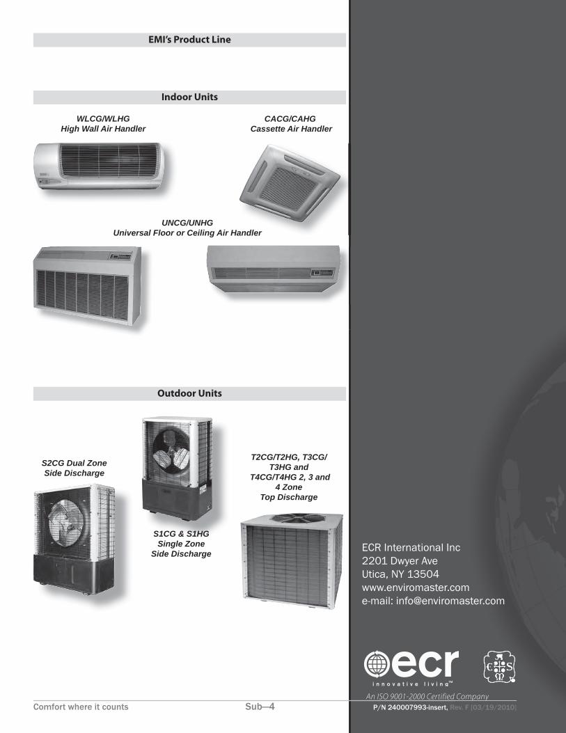
Indoor Units
Outdoor Units
S1CG & S1HG Single Zone
Side Discharge
S2CG Dual ZoneSide Discharge
WLCG/WLHGHigh Wall Air Handler
UNCG/UNHGUniversal Floor or Ceiling Air Handler
CACG/CAHG Cassette Air Handler
S1CG & S1HG
EMI’s Product Line
T2CG/T2HG, T3CG/T3HG and
T4CG/T4HG 2, 3 and 4 Zone
Top Discharge
P/N 240007993, Rev. E [03/3/2010] 7
WLCG/WLHG High-Wall Air Handlerswith EMI Condensers
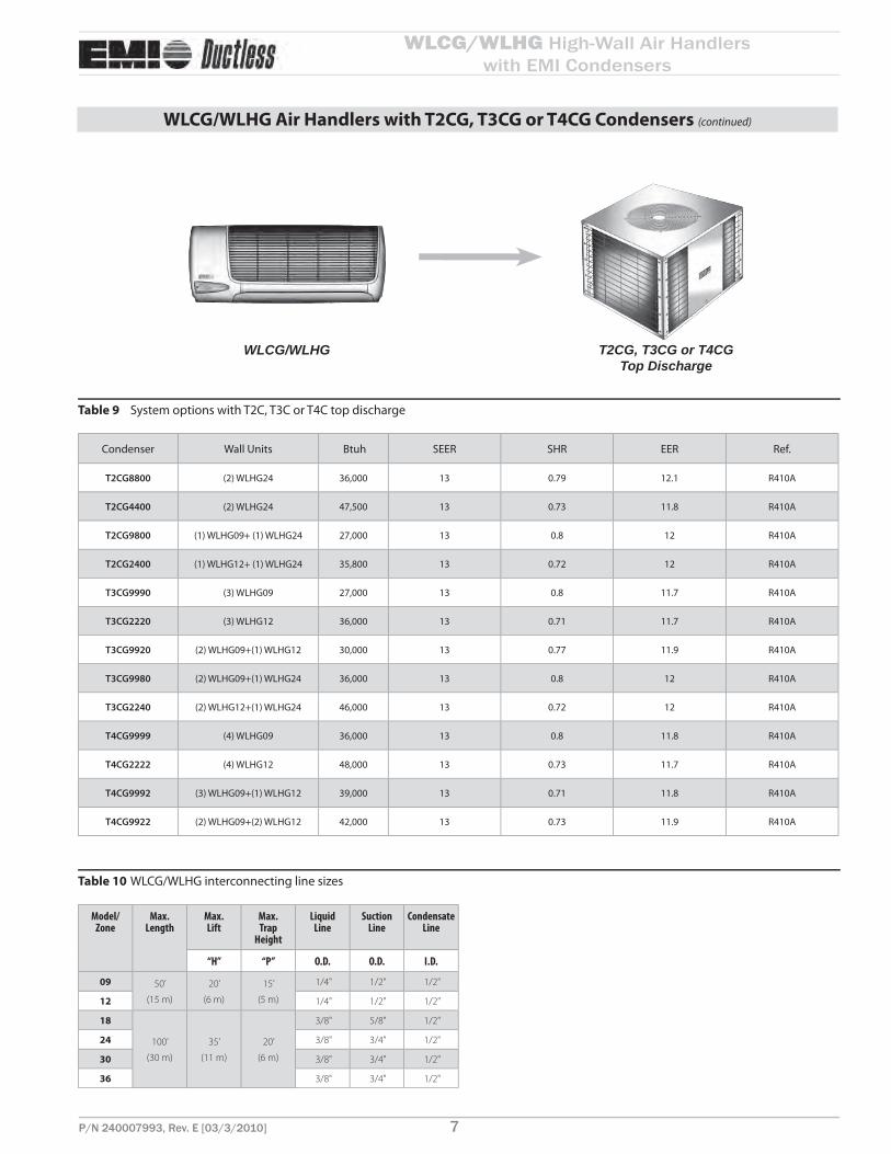
T2CG, T3CG or T4CG Top Discharge
System options with T2C, T3C or T4C top dischargeTable 9
Condenser Wall Units Btuh SEER SHR EER Ref.
T2CG8800 (2) WLHG24 36,000 13 0.79 12.1 R410A
T2CG4400 (2) WLHG24 47,500 13 0.73 11.8 R410A
T2CG9800 (1) WLHG09+ (1) WLHG24 27,000 13 0.8 12 R410A
T2CG2400 (1) WLHG12+ (1) WLHG24 35,800 13 0.72 12 R410A
T3CG9990 (3) WLHG09 27,000 13 0.8 11.7 R410A
T3CG2220 (3) WLHG12 36,000 13 0.71 11.7 R410A
T3CG9920 (2) WLHG09+(1) WLHG12 30,000 13 0.77 11.9 R410A
T3CG9980 (2) WLHG09+(1) WLHG24 36,000 13 0.8 12 R410A
T3CG2240 (2) WLHG12+(1) WLHG24 46,000 13 0.72 12 R410A
T4CG9999 (4) WLHG09 36,000 13 0.8 11.8 R410A
T4CG2222 (4) WLHG12 48,000 13 0.73 11.7 R410A
T4CG9992 (3) WLHG09+(1) WLHG12 39,000 13 0.71 11.8 R410A
T4CG9922 (2) WLHG09+(2) WLHG12 42,000 13 0.73 11.9 R410A
WLCG/WLHG interconnecting line sizesTable 10
Model/Zone
Max.Length
Max.Lift
Max.Trap
Height
LiquidLine
SuctionLine
CondensateLine
“H” “P” O.D. O.D. I.D.
09 50’
(15 m)
20’
(6 m)
15’
(5 m)
1/4" 1/2" 1/2"
12 1/4" 1/2" 1/2"
18
100’
(30 m)
35’
(11 m)
20’
(6 m)
3/8" 5/8" 1/2"
24 3/8" 3/4" 1/2"
30 3/8" 3/4" 1/2"
36 3/8" 3/4" 1/2"
WLCG/WLHG Air Handlers with T2CG, T3CG or T4CG Condensers (continued)
WLCG/WLHG

WLCG/WLHG High-Wall Air Handlerswith EMI Condensers
Comfort where it counts 8 P/N 240007993, Rev. E [03/3/2010]
WLCG/WLHG Air Handlers with T2HG, T3HG or T4HG Condensers
Dimensional data, sound data and shipping weightsTable 11
Model SizeSound
level
dBA
Shipping
weight
Lbs kg
T2HG 2400 70 325 147
T2HG 4400 70 325 147
T2HG 8800 70 325 147
T2HG 9800 70 325 147
T3HG 2240 70 325 147
T3HG 9980 70 325 147
T3HG 9990, 2220, 9920 70 325 147
T4HG 2222, 9922, 9992, 9999 70 325 147
Cooling Operational RangesTable 12
Unit Size
Accessories Part Numbers (Quantity) Required
*** Order ALL Kits Listed Under the Operational Range ***
Operational Range
32° to 115° F
(0 to 46° C)
0° to 115° F
(-18 to 46° C)
Crankcase
Heater Kit
Crankcase
Heater Kit
Fan Cycle Switch
Kit
Architectural
Louver/Hail Guard/
Wind Baffl e Kit
T2HG 2400, 9800 N/R N/R N/R 550002057
T2HG 4400, 8800 N/R N/R N/R 550002057
T3HG 2240, 9980 N/R N/R N/R 550002057
T3HG 9990, 2220, 9920 N/R N/R N/R 550002057
T4CG 2222, 9922, 9992, 9999 N/R N/R N/R 550002057
Note: N/R - Not Required
T2HG, T3HG or T4HG — descriptionEMI off ers the fi nest multi-zone heat pump outdoor units in the ductless split market, the T series (T2HB, T3HB & T4HB) condensing units. Th ese units allow the installation of two or more circuits from a single outside location, ideal for when space or aesthetic requirements limit the use of the number of cabinets outdoors. Each zone is independent so no mixing of refrigerant occurs.
NOTICE
When specifying heat pump(s), it is recommended that the matching indoor unit(s) be equipped with electric heat.
Features
Compressors — Hermetically-sealed high-effi ciency rotary or reciprocat-• ing types, depending on zone loads. Motors are PSC type with inherent overload protection. Compressors are installed on resilient mountings. All 9,000-12,000 Btuh units are equipped with a Duratec Performance • Package that includes an oversized suction accumulator with surge baffl es and enhanced oil management and a factory-installed solid core fi lter drier.Cabinet - Fabricated of G90U galvaneal steel, fi nished with corrosion • inhibiting, polyester, powder coated paint (2,000 hr. salt spray tested). Fan Guard — Black vinyl coated. Cabinet Color — Light gray & black.Refrigeration Circuit — Th e T2C, T3C, and T4C are delivered with • pre-charged refrigerant (R410A) for the condenser coils and evaporators. Charging of the fi eld-installed piping is required. Unit refrigeration valves are solid brass, for sweat connection. Solid core fi lter driers are factory installed on all models with rotary compressors.Condenser Coil — Th e condenser coils are tested to 600 psig and are • constructed of seamless copper tubing, arranged in staggered confi gura-tion, with enhanced aluminum fi ns. Th e tubes are mechanically expanded for secure bonding to fi n shoulder.Condenser Fan/Motor — Th e condenser fan is a large diameter, high ef-• fi ciency, three or four blade (depending on capacity) aluminum propeller type, directly connected to the totally enclosed, PSC motor. Th e motor is fi tt ed with internal thermal protection. Th ese multi-zone units are a draw-through air fl ow design.All 18,000 and 24,000 Btuh circuit units include a solid core fi lter drier • and high pressure limit switch. Th e 18,000 Btuh circuits also include a large capacity suction accumulator with surge baffl es and enhanced oil management.
Controls and components
(factory installed and supplied)
Compressor and fan motor contactor• Run capacitor• Low voltage terminal connections• High pressure switch with manual external reset• Heat pump hard start• Cooling operation down to 32°F (0°C) standard on all units• Cooling operation only available down to 32°F (0°C)• Models 9,000-12,000 Btuh only:•
Large capacity suction accumulator –Solid-core fi lter drier –
Thermostatically-controlled crankcase heater
Th is feature energizes the crankcase heater only when needed, saving • unnecessary power usage and increasing overall system effi ciency.
System options
Corrosion-resistant coil options (sea coast and harsh environment us-• age):
Copper fi n/copper tube condenser coil. –Coated aluminum fi n/copper tube condenser coil. –
Wind baffl es — louvers.•
Installer-supplied items
Power wiring.• Low-voltage wiring (18 awg minimum).• Secure mounting pad or foundation.• Refrigerant piping (if not purchased from EMI).• High-voltage disconnect.• Refrigerant for charging interconnect piping.•

P/N 240007993, Rev. E [03/3/2010] 9
WLCG/WLHG High-Wall Air Handlerswith EMI Condensers
WLCG/WLHG Air Handlers with T2HG, T3HG or T4HG Condensers (continued)
System options with T2H, T3H or T4H top dischargeTable 13
Condenser Air Handlers Cooling Btuh Heating Btuh SEER HSPF SHR EER COP Ref.
T2HG8800 (2) WLHG24 36,000 34,000 13.0 7.7 0.79 12.1 3.3 R410A
T2HG4400 (2) WLHG24 47,500 41,000 13.0 7.7 0.73 11.8 3.2 R410A
T2HG9800 (1) WLHG09+ (1) WLHG24 27,000 25,600 13.0 7.7 0.8 12 3.3 R410A
T2HG2400 (1) WLHG12+ (1) WLHG24 36,000 31,500 13.0 7.7 0.72 12 3.3 R410A
T3HG9990 (3) WLHG09 27,000 25,800 13.0 7.7 0.8 11.7 3.2 R410A
T3HG2220 (3) WLHG12 36,000 33,000 13.0 7.7 0.71 11.7 3.2 R410A
T3HG9920 (2) WLHG09+(1) WLHG12 30,000 28,200 13.0 7.7 0.77 11.9 3.2 R410A
T3HG9980 (2) WLHG09+(1) WLHG24 36,000 34,200 13.0 7.7 0.8 12 3.2 R410A
T3HG2240 (2) WLHG12+(1) WLHG24 46,000 42,500 13.0 7.7 0.72 12 3.3 R410A
T4HG9999 (4) WLHG09 36,000 34,400 13.0 7.7 0.8 11.8 3.2 R410A
T4HG9992(2) UNHG09
UNHG1239,000 35,900 13.0 7.7 0.76 11.5 3.4 R410A
T4HG2222 (4) WLHG12 48,000 49,000 13.0 7.7 0.73 11.7 3.2 R410A
T4HG9922 (2) WLHG09+(2) WLHG12 42,000 39,200 13.0 7.7 0.73 11.9 3.3 R410A
WLCG/WLHG interconnecting line sizesTable 14
Model/Zone
Max.Length
Max.Lift
Max.Trap
Height
LiquidLine
SuctionLine
CondensateLine
“H” “P” O.D. O.D. I.D.
09 50’
(15 m)
20’
(6 m)
15’
(5 m)
1/4" 1/2" 1/2"
12 1/4" 1/2" 1/2"
18
100’
(30 m)
35’
(11 m)
20’
(6 m)
3/8" 5/8" 1/2"
24 3/8" 3/4" 1/2"
30 3/8" 3/4" 1/2"
36 3/8" 3/4" 1/2"
T2HG, T3HG or T4HG Top Discharge
WLCG/WLHG

WLCG/WLHG High-Wall Air Handlerswith EMI Condensers
Comfort where it counts 10 P/N 240007993, Rev. E [03/3/2010]
Electrical Specifi cations
NOTICEDue to ongoing product development, designs, specifi cations, and performance are subject to change without notice. Please consult the factory for further information.
Electrical specifi cations — WLCG/WLHGTable 15
MODEL VOLTS/HZ/PHFANRLA
HP HEATER K.W. AMPSTOTALAMPS
MINVOLT
M.C.A.HACRBRKR
WLHG
09–12
115/60/1 0.64 0.02 – – 0.64 104 0.8 15
208/230/60/1 0.34 0.02 – – 0.34 197 0.4 15
208/230/60/1 0.34 0.02 3 13.04 13.38 197 16.7 20
WLHG
24
208/230/60/1 0.56 0.07 – – 0.56 197 0.7 15
208/230/60/1 0.56 0.07 3 13.04 13.6 197 17 20
208/230/60/1 0.56 0.07 5 21.74 22.3 197 27.9 30
WLCG
30/36
208/230/60/1 0.8 0.10 – – 0.8 197 1 15
208/230/60/1 0.8 0.10 5 21.74 22.54 197 28.2 30
Electrical specifi cations — S1CG/S1HG,S2CG/S2HGTable 16
Model # Volts/HZ/PH
Fan Motor Compressor
Total
amps
Min
voltM.C.A.
HACR
BRKRCircuit 1 Circuit 2
AMPS HP RLA LRA RLA LRA
S1CG9000AS1HG9000A
115/60/1 1.4 0.125 7.5 47 N/A 8.9 104 10.8 15
S1CG2000AS1HG2000A
115/60/1 1.4 0.125 9.9 53 N/A 11.3 104 13.8 20
S1CG9000DS1HG9000D
208/230/60/1 0.8 0.125 3.9 20 N/A 4.7 197 5.7 15
S1CG2000DS1HG2000D
208/230/60/1 0.8 0.125 5.2 27 N/A 6.0 197 7.3 15
S1CG8000DS1HG8000D
208/230/60/1 0.8 0.125 5.9 43 N/A 6.7 197 8.2 15
S1CG4000DS1HG4000D
208/230/60/1 0.8 0.125 8.0 43 N/A 8.8 197 10.8 15
S1CG3000D 208/230/60/1 1.8 0.330 11.6 74 N/A 13.4 197 16.3 25
S1CG6000D 208/230/60/1 1.8 0.330 11.5 79 N/A 13.3 197 16.2 25
S2CG2200DS2HG2200D
208/230/60/1 1.8 0.330 5.2 27 5.2 27 9.6 197 10.6 15
S2CG9200DS2HG9200D
208/230/60/1 1.8 0.330 3.9 20 5.2 27 10.9 197 12.2 15
S2CG9900DS2HG9900D
208/230/60/1 1.8 0.330 3.9 20 3.9 20 12.2 197 13.5 15
M.C.A. - minimum circuit amps

P/N 240007993, Rev. E [03/3/2010] 11
WLCG/WLHG High-Wall Air Handlerswith EMI Condensers
Electrical specifi cations — T2CG/T3CG/T4CG, T2HG/T3HG/T4HGTable 17
Model # Volts/HZ/PHFan Motor
Compressor
Zone-1
Compressor
Zone-2
Compressor
Zone-3
Compressor
Zone-4 Total
amps Min
volt
M.C.A.HACR
BRKRAMPS HP RLA LRA RLA LRA RLA LRA RLA LRA
T2CG2400D 208/230/60/1 1.8 0.33 5.2 27 8.2 58.3 15.2 17.3 25
T2CG4400D 208/230/60/1 1.8 0.33 8.2 58.3 8.2 58.3 18.2 197 20.3 25
T2CG8800D 208/230/60/1 1.8 0.33 5.9 43 5.9 43 13.6 197 15.1 20
T2CG9800D 208/230/60/1 1.8 0.33 3.9 20 5.9 43 11.6 197 13.1 15
T3CG2220D 208/230/60/1 1.8 0.33 5.2 27 5.2 27 5.2 27 17.4 197 18.7 20
T3CG2240D 208/230/60/1 1.8 0.33 5.2 27 5.2 27 8.2 58.3 20.4 197 22.5 30
T3CG9920D 208/230/60/1 1.8 0.33 3.9 20 3.9 20 5.2 27 14.8 197 16.1 20
T3CG9990D 208/230/60/1 1.8 0.33 3.9 20 3.9 20 3.9 20 13.5 197 14.5 15
T3CG9980D 208/230/60/1 1.8 0.33 3.9 20 3.9 20 5.9 43 15.5 197 17 20
T4CG2222D 208/230/60/1 1.8 0.33 5.2 27 5.2 27 5.2 27 5.2 27 22.6 197 23.9 25
T4CG9922D 208/230/60/1 1.8 0.33 3.9 20 3.9 20 5.2 27 5.2 27 20 197 21.3 25
T4CG9992D 208/230/60/1 1.8 0.33 3.9 20 3.9 20 3.9 20 5.2 27 18.7 197 20 25
T4CG9999D 208/230/60/1 1.8 0.33 3.9 20 3.9 20 3.9 20 3.9 20 17.4 197 18.4 20
T2HG2400D 208/230/60/1 1.8 0.33 5.2 27 8.2 58.3 15.2 197 17.3 25
T2HG4400D 208/230/60/1 1.8 0.33 8.2 58.3 8.2 58.3 18.2 197 20.3 25
T2HG8800D 208/230/60/1 1.8 0.33 5.9 43 5.9 43 13.6 197 15.1 20
T2HG9800D 208/230/60/1 1.8 0.33 3.9 20 5.9 43 11.6 197 13.1 15
T3HG2220D 208/230/60/1 1.8 0.33 5.2 27 5.2 27 5.2 27 17.4 197 18.7 20
T3HG2240D 208/230/60/1 1.8 0.33 5.2 27 5.2 27 8.2 58.3 20.4 197 22.5 30
T3HG9920D 208/230/60/1 1.8 0.33 3.9 20 3.9 20 5.2 27 14.8 197 16.1 20
T3HG9980D 208/230/60/1 1.8 0.33 3.9 20 3.9 20 5.9 43 15.5 197 17 20
T3HG9990D 208/230/60/1 1.8 0.33 3.9 20 3.9 20 3.9 20 13.5 197 14.5 15
T4HG2222D 208/230/60/1 1.8 0.33 5.2 27 5.2 27 5.2 27 5.2 27 22.6 197 23.9 25
T4HG9922D 208/230/60/1 1.8 0.33 3.9 20 3.9 20 5.2 27 5.2 27 20 197 21.3 25
T4HG9992D 208/230/60/1 1.8 0.33 3.9 20 3.9 20 3.9 20 5.2 27 18.7 197 20 25
T4HG9999D 208/230/60/1 1.8 0.33 3.9 20 3.9 20 3.9 20 3.9 20 17.4 197 18.4 20
M.C.A. - minimum circuit amps
Electrical Specifi cations (cont.)

ECR International Inc2201 Dwyer AveUtica, NY 13504www.enviromaster.come-mail: [email protected]
An ISO 9001-2000 Certified CompanyComfort where it counts 12 P/N 240007993, Rev. F [03/19/2010]
Indoor Units
Outdoor Units
S1CG/S1HG Single Zone
Side Discharge
S2CG/S2HG Dual ZoneSide Discharge
WLCG/WLHGHigh Wall Air Handler
UNCG/UNHGUniversal Floor or Ceiling Air Handler
CACG/CAHG Cassette Air Handler
S1CG/S1HG
T2CG/T2HG, T3CG/T3HG and
T4CG/T4HG 2, 3 and 4 Zone
Top Discharge
EMI’s Product Line