witness 14 release notes - addlink software científico 14 release notes.pdf · speed up 3d...
TRANSCRIPT
WITNESS 14 Release Notes
Introduction
The new 3D capability available in WITNESS 14 replaces all previous versions of Quick 3D, Fast Build
and VR. It is built on a new architecture that can support new presentation and gaming input devices
such as multiple monitors, stereoscopic monitors, presence detection and immersive, interactive 3D
environments. The architecture also takes advantage of modern multi-core processors to significantly
speed up 3D animation during simulation.
At a basic level the new 3D options operate as before, with the Quick 3D option to generate a 3D
model view based on the 2D model layout. However it is more powerful and has a wider range of
options. Many options are easier too due to using industry standard formats and direct importing into
WITNESS rather than via a third party product.
WITNESS users will notice the following major improvements:
i) Improved performance – all models run significantly faster in the new software. Tuning the
features on the various graphics cards available enables optimal frame rates and quality.
ii) Features such as shadows are available where supported by the graphics card – and the
quality of features such as antialiasing is much improved.
iii) There is an enhanced library of shapes and objects
iv) Options to import new 3D shapes are now inside WITNESS offering speed of selection
and use
v) Shapes may be imported using the popular COLLADA format (.dae) – this gives access to
thousands of free shapes directly from web and free products such as Sketchup and
Blender.
vi) Queuing positions of parts in relation to machine shapes can be set up directly within
WITNESS (the same applies to the position of parts on vehicles, vehicles on tracks, carriers
on sections, parts on conveyors, etc).
vii) Lines, Rectangles and Ellipses may be extruded. Each layer in WITNESS may be extruded
in a different material with different offsets allowing multiple layer 3D wall and other
constructs. Each layer may be extruded in an imported color/image.
viii) An animation may be imported with each 3D geometry in the COLLADA file. This may be
started and stopped using functions in the actions code.
Users may optionally extend the available options through the purchase of a new product called
“Visionary Render for WITNESS”. It gives users the opportunity to create immersive, interactive,
stereoscopic 3D virtual environments at the desktop or in single or multi-walled projected displays
(ActiveWall/PowerWall or ActiveCube/CAVE). These powerful new opportunities are possible through
our collaboration with world leading Virtual Reality Company Virtalis.
Visionary Render for WITNESS also includes features such as extensive direct import filters for the
highest possible quality of shape transfer and a scripting environment for direct manipulation of the
virtual world alongside and interacting with the simulation model. Please view full details on these
options through the link from the WITNESS Start Page and for enquiries please contact Lanner via the
Lanner website www.lanner.com
Hardware requirements for WITNESS Quick 3D and Visionary Render for WITNESS.
- WITNESS Quick 3D requires accelerated 3D graphics for proper and optimum performance.
Most middle to high specification laptops and desktops will contain a specialized graphics card
that delivers good performance.
- WITNESS Quick 3D is developed in an environment that utilizes NVIDIA graphics cards and
therefore these are the most tested graphics card options.
- For high-end performance where needed a K series Quadro graphics card is currently
recommended. http://www.nvidia.com/object/quadro-advantage.html
- For Visionary Render for WITNESS complete hardware/system solutions are available from
Virtalis. www.virtalis.com
A summary of the functionality of the release is included below with sections on methodology and
fuller description of functionality. This help system also includes reference pages for the dialogs and
commands available and there is an introduction to using 3D in Learning WITNESS Book Two.

Summary of Release
This is a summary in bullet point format of the new 3D functionality. For a full description of each item
please see the detailed information in the sections below.
WITNESS Quick 3D Functionality at a glance
Quick 3D and Customize Quick 3d options on model menu. These are the commands to create
a 3D view and a dialog that alters some of the options for how the view is created.
Display mapping - Icons in the picture gallery link to 3D objects. These objects by default scale
to the size drawn in 2D but this may be overridden with a different size and orientation. (for
example a small square at the top of the 2D screen can become a whole workshop
environment).
Choice of shapes - Links can be overridden for each element with a free choice from the 3D
shapes included in the WITNESS library as standard (over 100 shapes)
Shapes allow for queuing positions - Each object in the library has a defined queuing position –
i.e where other elements will appear in relation to that object. When a geometry is used as a
machine this is the part queuing position. Vehicle (part queuing position), carrier (part queuing
position), track (vehicle queuing position), section (carrier queuing position), conveyor (part
queuing position), etc.
No shapes required - All buffers and other queues (such as labor queues) have blank geometry
queuing options. Many elements have path displays in 2D that extrude a 3D object cross
section to form the path object in 3D – these include conveyors, tracks, paths, buffers and
sections). All paths allow for 3D settings in the paths toolbar.
Multi-floor options - Multiple floor options included using the layers dialog with height setting
and 2D offsets in 3D. Additional multiple scaling options.
Materials – Materials from the standard library can be applied to shapes (all faces) – for
example to create different colour cubes as parts.
ICON change functionality - When 2D icon is changed the 3D geometry can change too
WITNESS 3D functions - There are functions in WITNESS actions code to change 3D part
geometries (e.g. to create assemblies), effect animations, find and move 3D elements, and
Functions in this release include:
o W3DPart – changes the part geometry
o W3DGetElementInstance – identifies the current 3D geometry
o W3DGetPartInstance – identifies the current 3D part geometry
o W3DStartAnimation – starts an animation defined against the specified 3D geometry
o W3DStopAnimation – stops an animation defined against the specified 3D geometry
o W3DGetXPosn – Find the current 3D X Co-ordinate for the specified element display item
o W3DGetYPosn – Find the current 3D Y Co-ordinate for the specified element display item
o W3DGetZPosn – Find the current 3D Z Co-ordinate for the specified element display item
o W3DSetPosn – Sets the specified element display item 3D geometry to a new 3D location
o W3DPathOffset – Applies an offset to the specified 3D display item (when moving along a
path)
o W3DGeometry - Changes the geometry for the specified element’s display item
o W3DMaterial - Changes the material for the specified element’s display item
Lights/Camera - Lights are predefined in the view. A single camera is provided in the 3D view
as the viewpoint. Easy hotkey selection of overhead/side viewpoints. Easy hotkey return to
base if lost.
Easy Navigation - The 3D window can be navigated using a standard mouse – many move /
pan / tilt / orbit options.
Floor tiling - Floor color choices – set in the Model/Quick 3D Customize menu dialog
Wireframe options - Wireframe views are available at a keystroke
Carpet Images - Images in 2D can be taken through to the 3D view as a carpet. For example a
CAD layout can be shown as a carpet display on the floor in the 3D window.
High Performance - when compared to the old WITNESS VR. The new 3D technology from
Virtalis utilizes the latest graphics cards and their features. The new structure of the hosted 3D
window also means separate core processor power is utilized for the VR view offering higher
performance levels and larger model capability. An example of higher performance is clearly
seen in model flight - in the new WITNESS 3D the model no longer stops during flight (as in
the old WITNESS VR).
Shadows are enabled on the display for the first time in WITNESS. Includes switch to turn on
and off.
Other graphics step changes – e.g. Antialiasing (flicker and shimmer) is much improved when
used with graphics cards that support high quality in this area. Make sure to enable these
features (see below).
New materials can be defined from images. This can be done inside WITNESS and used to
cover the basic library shapes – can be used for logos, branding, product differentiation, etc.
New flight control - The flight options for 3D in WITNESS have been completely reworked to
enable simpler, more intuitive use. Less button options and more direct mouse and key
functionality.
Full Screen and Multiscreen support – View the 3D view full screen and/or on a separate
monitor
3D import capability - Importing of 3D objects using a widely accepted standard (COLLADA -
.dae files). These files are an export format from the free versions of SketchUp, Blender and
many other packages. Other formats can be easily converted to this format using standard
packages – for example 3DS files load into both SketchUp and Blender.
Use Free shapes from the web - 3D Warehouse shapes export directly into SketchUp for easy
export to .dae files. Therefore thousands of free shapes are available for use in WITNESS.
Many other sites offer high quality shapes too for all industries. The greater capability of
graphics handling in the new WITNESS 3D means that even complex shapes can be used.
Extended Import Capability with Visionary Render for WITNESS – This additional price option
extends import capability with direct data importers from a variety of additional formats. The
direct import capability offers greater compatibility and increased accuracy for larger and more
complex models.
Editing of Queuing Positions – For imported shapes (or copies of existing shapes) it is possible
to adjust the position and orientation of queuing positions – i.e. where parts (or vehicles or
carriers) appear in relation to the geometry.
Animation import – COLLADA (.dae files) can include an animation for a shape. This animation
can be started and stopped using WITNESS functions.

Methodology for Creating and Using a 3D view
Creating a View
WITNESS models are built in a 2D window. At any point in a model build or even during a simulation
run a 3D view can be created. This is done by using the Model/Quick 3D menu item from the Model
menu. This uses information from the 2D display and also other information contained in additional
dialogs. The 3D view is created in a new WITNESS window. The window is included in the list of
windows shown by the WITNESS Windows menu – by default this is called “3D View”. Access to this
window is the same as any other modelling window in WITNESS.
The 3D view that is created is the 3D representation of the model and this will dynamically update as
the model is run in exactly the same way as the 2D windows. When changes are made to the 2D
model that affect layout it is necessary to Quick 3D again in order for those changes to be reflected in
the 3D View.
Information used to construct the 3D view
The positioning of the 2D display items in the WITNESS 2D modelling windows. The view will
scale any icons, paths, etc, drawn to the size drawn on the 2D display, unless this is altered on
the 3D Mapping dialog for that display item. The view also takes into account the
Model/Options/Co-ordinates settings for scaling.
Elements that have a direct 3D representation are currently Parts, Machines, Buffers,
Conveyors, Tracks, Vehicles, PF Sections, PF Stations, PF Sections, Paths and Labor.
Information on the Element 3D Mapping dialogs. This can alter the size and orientation of
display items
The queue edit dialog settings for queue positions relative to an element. For example where a
part will appear in a machine, or a vehicle on a track. Note that the standard library objects have
these positions fixed by Lanner but customers may copy these and alter the queuing positions
and further may import their own 3D objects and set these details.
All path displays have height setting on the dialog accessed via the information button on the
paths toolbar (when the path is selected). These height settings will be reflected in the 3D
view for path displays drawn for Paths, Buffers, Conveyors, Tracks and PF Sections.
The Layers dialog, accessed from using the View/Layers menu enables display items to be
placed on different floors. Each floor can be at a different height for 3D – and additionally each
layer can be offset in x, y or z directions.
The Layers dialog also includes options for the extrusion of lines, rectangles and ellipses. Any
of these can be set to extrude to a set height and width and in a choice of color (or applied
image). This can create walls, windows, doorways, pictures and many other useful parts of a
3D display.
On a part style dialog is an option to scale parts according to size attributes. This will then use
the LENGTH, WIDTH and HEIGHT system attributes to scale the mapped 3D object
accordingly. Alternatively the native sizes of the objects will be used.
The Quick3D options dialogs provides options for floor colors and ceiling height - used to
position power and free sections (when hanging) above a floor.

Navigation of the 3D window using a standard mouse
The 3D window that is created using the Quick 3D process can be navigated using a standard mouse.
This moves the viewpoint (sometimes called the camera position) around the view. The window can be
navigated at any time – before, during and after a model run.
Forward and backwards movement Middle mouse button
Side to side movement Middle mouse button
Pan left or right and up or down Middle + right mouse buttons
Change angle of movement (up and down) Middle mouse button + Shift key
Orbit about the centre of the scene Middle mouse button + Ctrl key
Keyboard Controls
Ctrl W Turns Wireframe display on and off
Ctrl S Turns Shadows display on and off
Spacebar Returns camera to default view position
Number Keys 2,4,6,8 Give orthogonal views at each side of the model
Number Key 5 Gives an orthogonal overhead view of model
+ / - keys Press and release to accelerate and decelerate
flying speed. Multiple presses increase the effect.
Saving and Restoring of the 3D view
The 3D view is NOT saved with models – it must be recreated after a model is reloaded.

Detailed 3D functionality
Display mapping - Icons in the picture gallery link to 3D objects. These objects by default scale
to the size drawn in 2D but this may be overridden with a different size and orientation. (for
example a small square at the top of the 2D screen can become a whole workshop
environment).
To change a display mapping in the picture gallery simply right click on an icon and select 3D
Properties. This opens up a dialog where a different choice can be made. (or the mapping disabled by
selecting “No 3D Mapping” from the pull down list at the top of the dialog). A preview window of the
3D shape is shown to help selection. This preview window may be navigated using the same
navigation controls as the main 3D display i.e. the image may be orbited by pressing the Ctrl key,
pressing the middle mouse button/wheel and dragging the mouse.
Only change the mapping in the picture gallery when ALL elements that use that icon are to be
changed to a new 3D object. To change a single instance instead use the 3D link on the Style dialog of
the particular display item (see below for more on this).
For full details of all settings in the 3D Mapping dialog see the Dialogs section later in this document.
Choice of shapes - Links can be overridden for each element with a free choice from the 3D
shapes included in the WITNESS library as standard (over 100 shapes)
To change the 3D object mapping for a particular display item (icon, queue, etc.) select that display
items “Style” dialog. If the item is displayed this can be done by right clicking on the item and
selecting “Update Graphic”. If not then right click on the name of the item (on display or in the tree)
and select display. Then select draw and style in the first two boxes before using the first button to
access the style dialog.
Inside a style dialog there will be a 3D button. Press this to be taken to the 3D Mapping Dialog. In
addition to the dialog a preview pane is displayed which can be resized. The preview pane can also be
navigated using the mouse control options and keyboard commands in the same way as the main 3D
View window.
The 3D Mapping dialog sets the link from the 2D display item to a 3D representation. A set of options
is selectable from the top pull down menu. The default option is to use mapping from the picture
gallery.
The full list of options includes:
o No 3D Representation – turns off any 3D object link for this display item
o Basic 3D Representation – will use a basic representation for any linkage – same icon for all of
that element type – e.g. a machine icon will use the object called dg-ic-Machine. (this stands
for Default Geometry – ICON – Machine).
o Use Mapping from Picture Gallery. (In the picture gallery a link is set up linking an icon to a 3D
object).
o Use Defined Mapping – this will override the setting in the picture gallery and allow you to
select from the list displayed for this display item.
o Use as a Carpet – will draw the display item as a 2D carpet on the floor in the 3D display –
useful for CAD backdrops and other picture icons that can be used in this way
With these options if you wish to access a choice from the list select “Use Defined Mapping” and click
on the item required in the list. When another 3D object is selected in the list it will be shown in the
preview window:
By default WITNESS will make the 3D object match the size that the 2D display item is drawn on the
2D display. However using the fields here you can override the width, height and depth and the
orientation of the 3D display item. This is especially useful for environments such as workshops where
a small icon in one corner of the display can be mapped to a whole building to contain the model. For
an example try maintenance.mod in the sample models and see how the workshop is generated from
a small icon at the top left of the display.
For full details of all settings in the 3D Mapping dialog see the Dialogs section later in this document.
Shapes allow for queuing positions - Each object in the library has a defined queuing position –
i.e. where other elements will appear in relation to that object. When a geometry is used as a
machine this is the part queuing position. Vehicle (part queuing position), carrier (part queuing
position), track (vehicle queuing position), section (carrier queuing position), conveyor (part
queuing position), etc.
The default objects supplied have fixed queuing positions. However you may make a copy of any
object in order to redefine queuing positions. To copy an object use the copy button on the 3D
Mapping dialog - this will create a copy of the geometry and allow access to change the queuing
position. Note that these queuing settings can be set for all imported shapes too – allowing these to
position parts, etc in relation to the shape.
To access the Queue edit options use the Edit 3D button on the 3D Mapping dialog.
This allows the queuing position to be set in terms of base queue position (relative to the geometry),
the queuing direction and the rotation. Note that this information is not for the shape itself but for
queuing items associated with the shape.
This dialog has no relevance when used to map 3D Parts or Labor
o The dialog refers to part positions for elements such as machines, conveyors, paths and
vehicles
o The dialog refers to carrier or vehicle positions for section and track elements respectively
There is a choice in the pull down list for deciding whether it is the top edge, centre or bottom edge of
the queuing item that will align with the base queue position.
For full details of all settings in the 3D Mapping dialog see the Dialogs section later in this document.
For full details of all settings in the Queue Editor dialog see the Dialogs section later in this document.

No shapes required - All buffers and other queues (such as labor queues) have blank geometry
queuing options. In addition many elements have path displays in 2D that extrude a 3D object
cross section to form the path object in 3D – these include conveyors, tracks, paths, buffers
and sections). All path creation in 3D takes account of the 3D settings for that path accessed
via the information button on the paths toolbar.
For some display types it is optional to have a geometry displayed with a queuing position. However
the 3D for this type of display is chosen in exactly the same way as described above – by accessing
the style dialog for that display item.
Where a 3D shape is not required choose a blank shape (there are some in the basic library – e.g. dg-
pa-path) and define, if required, any changes to the queuing position as described in the section above.
For path display types further 3D information may be entered as to the height of the path display along
its length. Select the path on the model display and then select “i” on the path toolbar. This displays
information about the path including a starting height and a change of height for each straight or curved
section of the path.
For a machine if no icon is selected to link to 3D (i.e. any drawn icons have the option “No 3D
Representation” selected in the pull down list) then the part queue position itself may link to a 3D
geometry in order to position the part separately to any icon display.
Multi-floor options - Multiple floor options included using the layers dialog with height setting
and 2D offsets in 3D. Additional multiple scaling options.
In the View/Layers dialog VRx, VRy and VRz can offset each layer display in WITNESS 2D to a different
position in 3D – to enable one level in a building to be positioned over another level (for example). Also
each layer can be assigned to a different floor and the heights set for each floor.
This dialog also contains the settings for multiple layer extrusion options. These settings enable lines,
rectangles and ellipses drawn on each layer to be extruded to different widths, heights and in different
materials. A preview of the material chosen for each layer is show (when a layer is selected) and a
button below the preview frame allows new images to be imported (from JPG format) to act as new
materials.
Materials – Materials from the standard library can be applied to shapes (all faces) – for
example to create different color cubes as parts.
On the 3D Mapping dialog it is possible to select a different material to cover an entire shape. How the
image is applied to the different surfaces is set in each shape and cannot be changed inside WITNESS.
For imported shapes it is of course possible to change this mapping in the authoring software.
For full details of all settings in the 3D Mapping dialog see the Dialogs section later in this document.
New materials can be defined from images. This can be done inside WITNESS and used to
cover the basic library shapes – can be used for logos, branding, product differentiation, etc.
Using the 3D Mapping dialog or the button on the layers dialog a new image can be imported (from
JPG format). On the 3D Mapping dialog use the button to the right of the material selector. In the
Layers dialog use the Import button underneath the material preview.
Great improvements in performance - when compared to the old WITNESS VR. The new 3D
technology from Virtalis utilizes the latest graphics cards and their features. The new structure
of the hosted 3D window also means separate core processor power is utilized for the VR
view offering higher performance levels and larger model capability. An example of higher
performance is clearly seen in model flight - in the new WITNESS 3D the model no longer
stops during flight (as in the old WITNESS VR).
Other graphics step changes – e.g. Antialiasing (flicker and shimmer) is much improved when
used with graphics cards that support high quality in this area. Make sure to enable these
features
The graphics performance that you get will be dependent on the graphics card you have. Integrated
graphics are not as effective as dedicated graphics cards. The graphics cards we have most experience
in using are the NVIDIA graphics cards. For most dedicated graphics cards the results obtained should
be good but it will depend on the card and the settings. Some of the key settings are explained below
for an NVIDIA card – although in general the better quality options for any card should be selected.
Graphics Card Settings recommended:
o For Antialiasing choose an override option and a minimum of 8x if your graphics
performance is suitable for this.
o Textures – choose high quality settings
o Texture Filtering – Optimization – On
There are many different graphics cards available and it may be necessary to trial various settings to
obtain the best results.
3D import capability - Importing of 3D objects using a widely accepted standard (COLLADA -
.dae files). These files are an export format from the free versions of SketchUp, Blender and
many other packages. Other formats can be easily converted to this format using standard
packages – for example 3DS files load into both SketchUp and Blender.
Use Free shapes from the web - 3D Warehouse shapes transfer directly into SketchUp for
easy export to .dae files. Therefore thousands of free shapes are available for use in WITNESS.
Many other sites offer high quality shapes too for all industries. The greater capability of
graphics handling in the new WITNESS 3D means that even complex shapes can be used.
When you are setting up a defined mapping either in the picture gallery – or overriding that setting in
the individual graphic update dialog you may import a new shape by selecting the “Import 3D Shape
from File” button above the shape list. This allows the selection of a Collada file (.dae) for import.
Navigate to a directory where you have a .dae file that you wish to load and choose the open option
from the dialog. This will bring the new shape into WITNESS. If the shape is to be used as a machine,
vehicle, buffer, etc then you must then set the queuing position as described in a section above. For
parts and labor there are no additional settings needed.
Free programs that export Collada files include Sketchup and Blender. Using these programs the
shapes can also contain animations for use with the model.
For full details of all settings in the 3D Mapping dialog (including copying 3D shapes please see the
Dialogs section later in this document.
Extended Import Capability with Visionary Render for WITNESS – This additional price option
extends import capability with direct data importers from a variety of additional formats. The
direct import capability offers greater compatibility and increased accuracy for larger and more
complex models.
This option allows many other formats to be imported directly with ease. The software
provided is separate to core WITNESS and will convert the shapes to VRNative format which is
the format used directly by WITNESS 3D. Shapes in this format can be imported in the same
way as described above. In addition with the Visionary Render for WITNESS option worlds can
be extended directly, bypassing the need for WITNESS import.
Carpet Images - Images in 2D can be taken through to the 3D view as a carpet. For example a
CAD layout can be shown as a carpet display on the floor in the 3D window.
To use an image on the 2D screen as a ‘carpet’ in 3D (i.e. drawn on the floor – e.g. CAD diagram or
other graphic for labelling) simply right click on the graphic and select Update graphic. Then select 3D
and choose the “Use as a Carpet” option from the pull down list.
Note that no preview of this appears in the 3D preview window. In 3D the graphic, in this example the
map, will be drawn to scale (as in 2D) on the floor of the appropriate 3D layer. Graphics need not be
displayed in 2D (i.e. the layer can be turned off) – the 3D representation if set will still be generated.
Floor Tiling Colors and Power and Free Rail height
These are options that can be changed in the Model/Customize Quick 3D (Preview) menu dialog
The Power and Free rail height is the default height for Power and Free sections – above the floor that
they are drawn on (the setting is the same for all floors). The heights set in the path information dialog
(see earlier) add to this height.
The size of the tiling obtained for the floor depends on the co-ordinate settings in the
Model/Options/Co-ordinates dialog. To achieve a plain floor simply set make both color choices the
same.

ICON change functionality - When 2D icon is changed the 3D geometry can change too. At any
point in the actions language the command ICON=xxx can be used (were xxx is a valid icon
number). Not only will the icon in 2D change – but the 3D representation of the shape will
change to that associated with that icon in the picture gallery. (see also function W3DPart in
the functions list).
WITNESS 3D functions - There are many new functions in WITNESS actions code that affect
3D views. For example to change 3D part geometries (e.g. create assemblies), start and stop
animations, find and move 3D elements, change materials and more – full details are given in
the functions list in these release notes.
The New Quick 3D Menu and Toolbar Items
On the Model menu there are 3 new menu items. There is also a new Quick3D toolbar button
(including the text “Quick3D”) that builds a 3D view of the current model.
o The “Quick 3D” menu option will build a 3D view of the current model.
o The “Close Quick 3D” menu option will remove any 3D links from the current model and close
any 3D windows.
o The “Customize Quick 3D…” menu option will bring up a dialog to enable Quick 3D options to
be modified.

The 3D Dialogs
3D Mapping Dialog
This dialog can be accessed using the 3D button on any display item style dialog. If the button is not
present then this type of display item is not currently supported in 3D.
The dialog can also be accessed from the Picture gallery to set up default links for each 2D icon. To
access from the picture gallery right click on an icon and choose 3D properties.
A preview window of the 3D shape is shown to help selection. This preview window may be navigated
using the same navigation controls as the main 3D display i.e. the image may be orbited by pressing
the Ctrl key, pressing the middle mouse button/wheel and dragging the mouse.
Dialog Settings
Mode
This pull down list allows the following choices
No 3D Representation – turns off any 3D object link for this display item
Basic 3D Representation – will use a basic representation for any linkage – same icon for all of
that element type – e.g. a machine icon will use the object called dg-ic-Machine. (this stands
for Default Geometry – ICON – Machine).
Use Mapping from Picture Gallery. (this option is not available on this dialog when it is
accessed from the picture gallery)
Use Defined Mapping – this will override the setting in the picture gallery and allow you to
select from the list displayed for this display item.
Use as a Carpet – will draw the display item as a 2D carpet on the floor in the 3D display –
useful for CAD backdrops and other picture icons that can be used in this way
Hint: Elements often have more than one display in a 2D model. For example a machine frequently has
two icons; the first is a picture representation of what the machine looks like, the second is a simple
box to show the status color of the machine. Quick 3D will produce its activity display from the first
icon it finds. To ensure that the ‘picture’ icon is used, it is safest to override the 3D option for the
status icon to ‘No 3D Representation’.
3D Objects
An object in this list can be selected when the “Use Defined Mapping” option is set as the mode (see
above)
The buttons above this list have the following functionality:
Import 3D shape from file: This button allows the import of a new shape in COLLADA (.dae)
format to add to the list of 3D shapes.
Delete 3D Object – This button can be used to delete the selected 3D object from the list.
Please note that the standard library shapes cannot be deleted.
Copy 3D Object – This button is used to create a new copy of an existing 3D object in the list.
The new shape is named (with Copy added) and the shape is placed in the list.
Edit 3D Object Queue Properties – This button opens up the Queue Editor dialog for the
selected 3D shape. This enables the definition of where parts will appear in relation to a
machine shape, parts on a vehicle, vehicles on a track, etc. Please note that the standard
library shapes cannot have their queue positions changed – to change these first make a copy.
Material
Choose an option from this list if you want to change the look of the shape selected with a
single color or texture applied to all faces of that shape. Choose Original to revert to the original
textures and colors. The button beside the pull down selector enables a new texture to be
loaded to the list – simple select any JPG file.
How an image is applied to the different surfaces of a shape is set in each shape and cannot
be changed inside WITNESS. For imported shapes it is of course possible to change this
mapping in the authoring software.
3D Dimensions
The default option for the 3D shape will be to draw it the same size in 3D as defined by the
item display in 2D. To override this enter the appropriate width, depth and height. The height
can be automatically scaled to the set width and depth if desired. If the fields are left blank
then the default will apply.
Orientation (degrees)
The default option for the 3D shape will be to draw it in the same orientation as the 2D display
item. This can be overridden by entering a figure between -359 and 359 in these boxes.
Figures outside this range will be automatically changed to the appropriate value within the
range.
Shape names in the list
The names in the list are written in the style dg-xx-yyyyyyy
1. dg stands for default geometry
2. xx stands for the type of display item it is intended to represent.
3. yyyyyy is the name
New names do NOT have to follow these rules. These names help users of the old VR module to
recognise old favorites – as this was the syntax used for that module. The xx – type of display – is an
indication only – you may use any 3D shape for any 3D display item that supports 3D. All shapes can
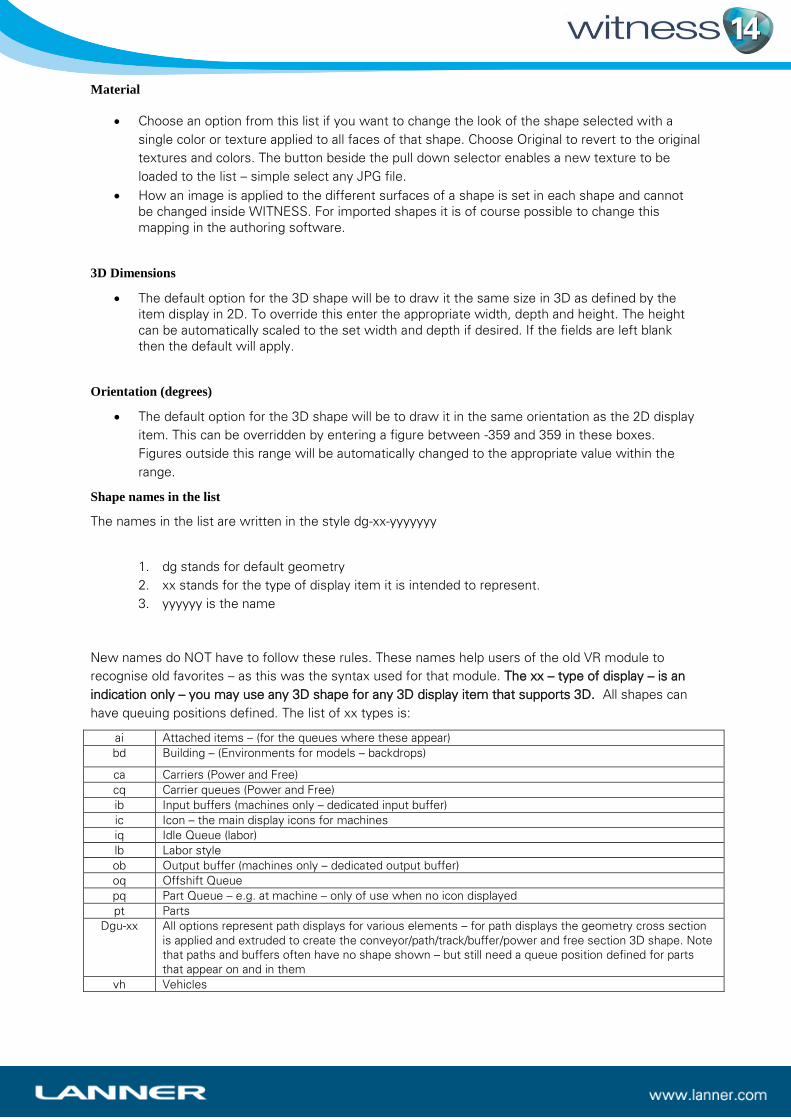
have queuing positions defined. The list of xx types is:
ai Attached items – (for the queues where these appear)
bd Building – (Environments for models – backdrops)
ca Carriers (Power and Free)
cq Carrier queues (Power and Free)
ib Input buffers (machines only – dedicated input buffer)
ic Icon – the main display icons for machines
iq Idle Queue (labor)
lb Labor style
ob Output buffer (machines only – dedicated output buffer)
oq Offshift Queue
pq Part Queue – e.g. at machine – only of use when no icon displayed
pt Parts
Dgu-xx All options represent path displays for various elements – for path displays the geometry cross section
is applied and extruded to create the conveyor/path/track/buffer/power and free section 3D shape. Note
that paths and buffers often have no shape shown – but still need a queue position defined for parts
that appear on and in them
vh Vehicles
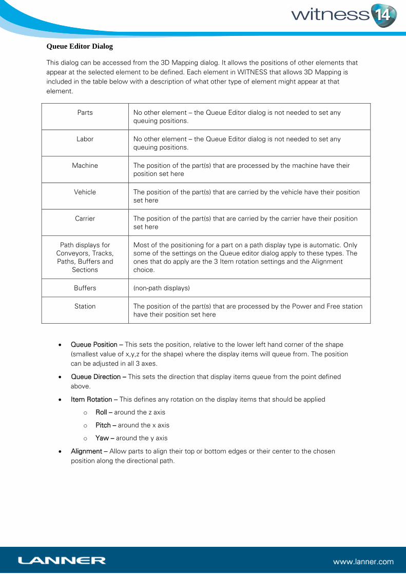
Queue Editor Dialog
This dialog can be accessed from the 3D Mapping dialog. It allows the positions of other elements that
appear at the selected element to be defined. Each element in WITNESS that allows 3D Mapping is
included in the table below with a description of what other type of element might appear at that
element.
Parts No other element – the Queue Editor dialog is not needed to set any
queuing positions.
Labor No other element – the Queue Editor dialog is not needed to set any
queuing positions.
Machine The position of the part(s) that are processed by the machine have their
position set here
Vehicle The position of the part(s) that are carried by the vehicle have their position
set here
Carrier The position of the part(s) that are carried by the carrier have their position
set here
Path displays for
Conveyors, Tracks,
Paths, Buffers and
Sections
Most of the positioning for a part on a path display type is automatic. Only
some of the settings on the Queue editor dialog apply to these types. The
ones that do apply are the 3 Item rotation settings and the Alignment
choice.
Buffers (non-path displays)
Station The position of the part(s) that are processed by the Power and Free station
have their position set here
Queue Position – This sets the position, relative to the lower left hand corner of the shape
(smallest value of x,y,z for the shape) where the display items will queue from. The position
can be adjusted in all 3 axes.
Queue Direction – This sets the direction that display items queue from the point defined
above.
Item Rotation – This defines any rotation on the display items that should be applied
o Roll – around the z axis
o Pitch – around the x axis
o Yaw – around the y axis
Alignment – Allow parts to align their top or bottom edges or their center to the chosen
position along the directional path.

A preview window of the 3D shape and queue position is shown to help editing. This preview window
may be navigated using the same navigation controls as the main 3D display i.e. the image may be
orbited by pressing the Ctrl key, pressing the middle mouse button/wheel and dragging the mouse.
The Ctrl W key is also active to show the wireframe display – and the number pad keys to select
orthogonal views (5 for overhead, 2,4,6,8 for side views, 0 for 3D standard view).
The Gold Cube shows the position of the start of the vector along which parts will appear – the grey
cubes show the direction of the queue.
The colored squares and cones on the cubes represent the direction of the part orientation within the
queue. The cones point in the direction of orientation and colors represent the orientation – (red x,
green y and blue z).
When values in the dialog are changed the cube positions in the view will update to show the new
queue positions and orientation.
Press the OK button on the dialog when all changes have been completed to save these for this shape.
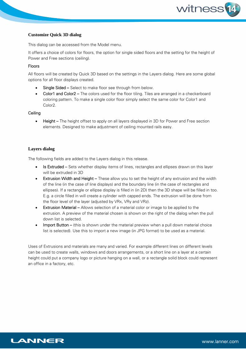
Customize Quick 3D dialog
This dialog can be accessed from the Model menu.
It offers a choice of colors for floors, the option for single sided floors and the setting for the height of
Power and Free sections (ceiling).
Floors
All floors will be created by Quick 3D based on the settings in the Layers dialog. Here are some global
options for all floor displays created.
Single Sided – Select to make floor see through from below.
Color1 and Color2 – The colors used for the floor tiling. Tiles are arranged in a checkerboard
coloring pattern. To make a single color floor simply select the same color for Color1 and
Color2.
Ceiling
Height – The height offset to apply on all layers displayed in 3D for Power and Free section
elements. Designed to make adjustment of ceiling mounted rails easy.
Layers dialog
The following fields are added to the Layers dialog in this release.
Is Extruded – Sets whether display items of lines, rectangles and ellipses drawn on this layer
will be extruded in 3D
Extrusion Width and Height – These allow you to set the height of any extrusion and the width
of the line (in the case of line displays) and the boundary line (in the case of rectangles and
ellipses). If a rectangle or ellipse display is filled in (in 2D) then the 3D shape will be filled in too.
E.g. a circle filled in will create a cylinder with capped ends. The extrusion will be done from
the floor level of the layer (adjusted by VRx, VRy and VRz).
Extrusion Material – Allows selection of a material color or image to be applied to the
extrusion. A preview of the material chosen is shown on the right of the dialog when the pull
down list is selected.
Import Button – (this is shown under the material preview when a pull down material choice
list is selected). Use this to import a new image (in JPG format) to be used as a material.
Uses of Extrusions and materials are many and varied. For example different lines on different levels
can be used to create walls, windows and doors arrangements, or a short line on a layer at a certain
height could put a company logo or picture hanging on a wall, or a rectangle solid block could represent
an office in a factory, etc.

The 3D Functions
There are many functions that can be used in the WITNESS actions language that will affect 3D
displays. These include:
W3DPart – changes the part geometry
W3DPathOffset – Applies an offset to the specified 3D display item (when moving along a
path)
W3DGetElementInstance – identifies the current 3D geometry
W3DGetPartInstance – identifies the current 3D part geometry
W3DStartAnimation – starts an animation defined against the specified 3D geometry
W3DStopAnimation – stops an animation defined against the specified 3D geometry
W3DGetXPosn – Find the current 3D X Co-ordinate for the specified element display item
W3DGetYPosn – Find the current 3D Y Co-ordinate for the specified element display item
W3DGetZPosn – Find the current 3D Z Co-ordinate for the specified element display item
W3DSetPosn – Sets the specified element display item 3D geometry to a new 3D location
W3DGeometry - Changes the geometry for the specified element’s display item
W3DMaterial - Changes the material for the specified element’s display item
W3DPart(Geometry)
This function is a void function in that it does not return any value.
Parameter Parameter Data Type Description
Geometry String The 3D geometry name to set the current
active part to
It is used to change the 3D shape associated with a part when that part being worked on – e.g. Actions
on entry into a machine, Actions on finish for a machine.
Examples:
W3DPart(“dg-pt-Carton”) Changes the current part geometry to dg-pt-Carton
W3DPart(“Cube”) Changes the current part geometry to an imported geometry called Cube
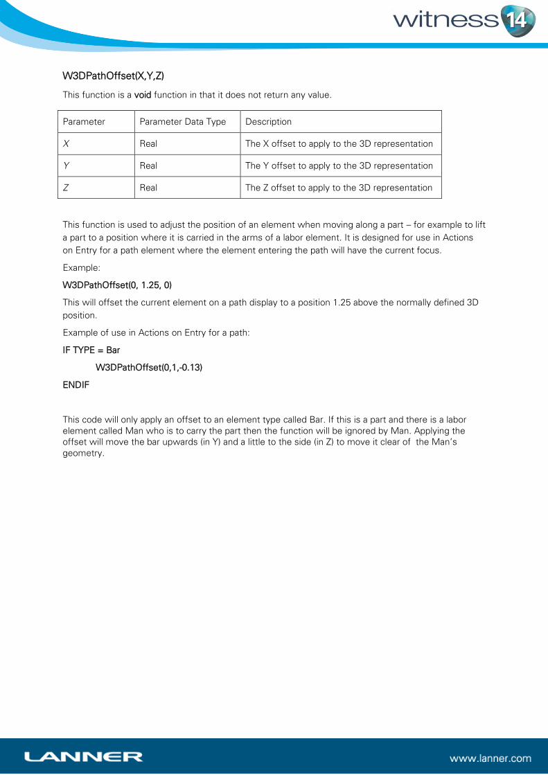
W3DPathOffset(X,Y,Z)
This function is a void function in that it does not return any value.
Parameter Parameter Data Type Description
X Real The X offset to apply to the 3D representation
Y Real The Y offset to apply to the 3D representation
Z Real The Z offset to apply to the 3D representation
This function is used to adjust the position of an element when moving along a part – for example to lift
a part to a position where it is carried in the arms of a labor element. It is designed for use in Actions
on Entry for a path element where the element entering the path will have the current focus.
Example:
W3DPathOffset(0, 1.25, 0)
This will offset the current element on a path display to a position 1.25 above the normally defined 3D
position.
Example of use in Actions on Entry for a path:
IF TYPE = Bar
W3DPathOffset(0,1,-0.13)
ENDIF
This code will only apply an offset to an element type called Bar. If this is a part and there is a labor
element called Man who is to carry the part then the function will be ignored by Man. Applying the
offset will move the bar upwards (in Y) and a little to the side (in Z) to move it clear of the Man’s
geometry.

W3DGetElementInstance(Element, Display)
This function returns a string value
Parameter Parameter Data
Type
Description
Element Name A valid WITNESS element name
Display String The 2D label name of the display item that links to the 3D
instance required
This function is used to find the unique ID of a 3D shape. This can then be used to apply an action to
that shape using the W3DStartAnimation function. W3DGetElementInstance is also used in
conjunction with the W3DGetXPosn, W3DGetYPosn, W3DGetZPosn and W3DSetPosn functions when
the location of 3D shapes is accessed and moved.
The 2D label for a display item is shown in the update graphic or style dialog for the display item. These
labels need not be unique and hence this function will use the first display item found with the
specified label. As an example of this a machine element in WITNESS may be represented by two
icons e.g. a picture icon and a status icon and by default these may both have the label “icon”. To
allow each to be identified, and hence moved or animated, it is necessary to assign a unique label to
each icon. For example the picture icon label may be changed to “Picture Icon” and the status icon
label may be changed to “Status Icon”.
Examples:
W3DGetElementInstance (MachineA(1),”Icon”)
This will return the 3D identity in string form of the 3D shape associated with the display item labelled
Icon for MachineA(1).
W3DGetElementInstance(Element,”Icon”)
This will return the 3D identity in string form of the 3D shape associated with the display item labelled
Icon for the element with the current focus. E.g. this could be used in “Actions on Start” for a machine
– in which case the machine would be the element for which the 3D identity of the icon is returned.

W3DGetPartInstance()
This function returns a string value
There are no parameters.
This function is used to find the unique ID of the part element with current focus. This can then be
used to apply an action to that shape using the W3DStartAnimation function.
Examples:
W3DGetPartInstance() when used in Actions on Create for a part can be used to store the identity of
the 3D shape linked to that part in a string attribute for future reference throughout the model.
W3DGetPartInstance() when used in Actions on Finish for a Machine can be used to access the
identity of the 3D shape linked to the part being finished in order to start an animation in the same
actions.
W3DGetPartInstance() when used in Actions on Start for a Machine can be used to access the identity
of the 3D shape linked to the first part being processed by the machine in order to start an animation in
the same actions. (Note that these actions are only run once in WITNESS (unlike Actions on Finish
which are run for each part).
W3DGetPartInstance() when used in Actions on Entry for a Machine can be used to access the identity
of the 3D shape linked to the part entering the machine in order to start an animation in the same
actions.

W3DStartAnimation(Instance, Animation, Time, Repeat)
This function is a void function in that it does not return any value.
Parameter Parameter
Data Type
Description
Instance String The identity of the 3D geometry for the animation to be applied to
Animation String The identity of the animation to be applied
Time Real Duration of animation (or -1 to use the original animation time set in the dae file). dae
files are the format in which 3D shapes and animations are imported into WITNESS
Repeat Integer The number of times the animation should repeat (or -1 for infinite). Please Note that
although this parameter is necessary this feature is NOT implemented in this release
– i.e. currently this parameter has no effect and all animations will repeat until
stopped. Therefore currently to effect a single animation cycle the duration of the
animation must be set to last for the entire time that the animation will be active
before being stopped.
This function is used to start animation effects on the objects in the 3D world. This is in addition to any
animations in the simulation model that are due to normal element dynamic displays – e.g. conveyor
movement, vehicle movement, path movement, etc. Animations can be imported in WITNESS in the
dae files used to import the 3D shapes. i.e. a shape can contain an animation (at any level in its
hierarchy). These animations need to be set up in whichever external package is used for 3D modelling
and animation and then included in the dae file saved from that application. If different animation
names are not set in the dae file by the application used then all actions in the dae file are combined in
a single action – called xxxx_Sequence where xxxx is the name of the geometry being imported.
To view animations when the model is run WITNESS also needs to be told how often to update
animations – this is done by setting the Model/Options on the Plugins tab. A suitable animation interval
should be chosen and the “Broadcast to Plugins” box ticked.
Examples
W3DStartAnimation(StringID,”Cube_Sequence”,4.5,1)
This command will apply the animation Cube_Sequence to the 3D shape identified by StringID. Note
that this will need to be a string variable or attribute and will need to be set using
W3DGetElementInstance or W3DGet PartInstance before being used in this function. The action will
be scaled to occur over 4.5 simulation time units and will occur only once. Note that the figure of 4.5
overrides the timing set for the action in the dae file – in this way the action can be fitted to difference
cycle times, etc.
W3DStartAnimation(StringID,”Cube_Sequence”,0.5,3)
This command will apply the animation Cube_Sequence to the 3D shape identified by StringID. Note
that this will need to be a string variable or attribute and will need to be set using
W3DGetElementInstance or W3DGet PartInstance before being used in this function). The action will
be scaled to occur over 0.5 simulation time units and will occur 3 times. Note that the figure of 0.5
overrides the timing set for the action in the dae file – in this way the action can be fitted to difference
cycle times, etc. If the cycle time of a machine is 3.85 and this example is used in Actions on Start
then the action will occur until time 1.5 and then no further animation will occur.
W3DStartAnimation(StringID,”Cube_Sequence”,0.5,-1)
In this example the animation Cube_Sequence will occur on the 3D shape identified in StringID until
told to stop by a W3DStopAnimation function OR in the case of a part it moves to another element, in
which case the animation is stopped automatically.
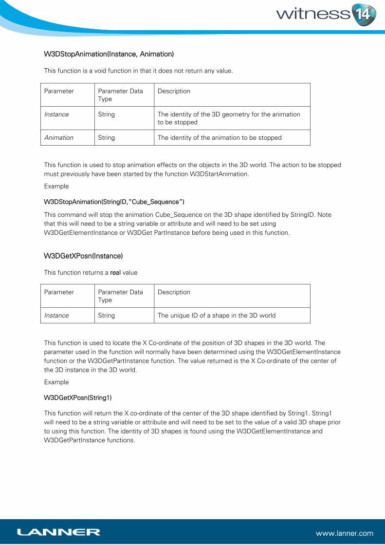
W3DStopAnimation(Instance, Animation)
This function is a void function in that it does not return any value.
Parameter Parameter Data
Type
Description
Instance String The identity of the 3D geometry for the animation
to be stopped
Animation String The identity of the animation to be stopped
This function is used to stop animation effects on the objects in the 3D world. The action to be stopped
must previously have been started by the function W3DStartAnimation.
Example
W3DStopAnimation(StringID,”Cube_Sequence”)
This command will stop the animation Cube_Sequence on the 3D shape identified by StringID. Note
that this will need to be a string variable or attribute and will need to be set using
W3DGetElementInstance or W3DGet PartInstance before being used in this function.
W3DGetXPosn(Instance)
This function returns a real value
Parameter Parameter Data
Type
Description
Instance String The unique ID of a shape in the 3D world
This function is used to locate the X Co-ordinate of the position of 3D shapes in the 3D world. The
parameter used in the function will normally have been determined using the W3DGetElementInstance
function or the W3DGetPartInstance function. The value returned is the X Co-ordinate of the center of
the 3D instance in the 3D world.
Example
W3DGetXPosn(String1)
This function will return the X co-ordinate of the center of the 3D shape identified by String1. String1
will need to be a string variable or attribute and will need to be set to the value of a valid 3D shape prior
to using this function. The identity of 3D shapes is found using the W3DGetElementInstance and
W3DGetPartInstance functions.
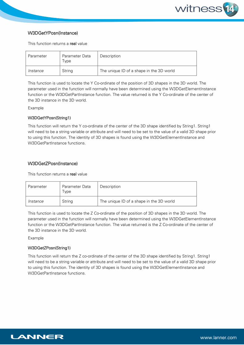
W3DGetYPosn(Instance)
This function returns a real value
Parameter Parameter Data
Type
Description
Instance String The unique ID of a shape in the 3D world
This function is used to locate the Y Co-ordinate of the position of 3D shapes in the 3D world. The
parameter used in the function will normally have been determined using the W3DGetElementInstance
function or the W3DGetPartInstance function. The value returned is the Y Co-ordinate of the center of
the 3D instance in the 3D world.
Example
W3DGetYPosn(String1)
This function will return the Y co-ordinate of the center of the 3D shape identified by String1. String1
will need to be a string variable or attribute and will need to be set to the value of a valid 3D shape prior
to using this function. The identity of 3D shapes is found using the W3DGetElementInstance and
W3DGetPartInstance functions.
W3DGetZPosn(Instance)
This function returns a real value
Parameter Parameter Data
Type
Description
Instance String The unique ID of a shape in the 3D world
This function is used to locate the Z Co-ordinate of the position of 3D shapes in the 3D world. The
parameter used in the function will normally have been determined using the W3DGetElementInstance
function or the W3DGetPartInstance function. The value returned is the Z Co-ordinate of the center of
the 3D instance in the 3D world.
Example
W3DGetZPosn(String1)
This function will return the Z co-ordinate of the center of the 3D shape identified by String1. String1
will need to be a string variable or attribute and will need to be set to the value of a valid 3D shape prior
to using this function. The identity of 3D shapes is found using the W3DGetElementInstance and
W3DGetPartInstance functions.
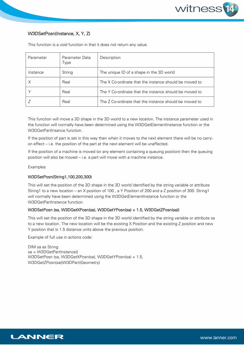
W3DSetPosn(Instance, X, Y, Z)
This function is a void function in that it does not return any value.
Parameter Parameter Data
Type
Description
Instance String The unique ID of a shape in the 3D world
X Real The X Co-ordinate that the instance should be moved to
Y Real The Y Co-ordinate that the instance should be moved to
Z Real The Z Co-ordinate that the instance should be moved to
This function will move a 3D shape in the 3D world to a new location. The instance parameter used in
the function will normally have been determined using the W3DGetElementInstance function or the
W3DGetPartInsance function.
If the position of part is set in this way then when it moves to the next element there will be no carry-
on effect – i.e. the position of the part at the next element will be unaffected.
If the position of a machine is moved (or any element containing a queuing position) then the queuing
position will also be moved – i.e. a part will move with a machine instance.
Examples
W3DSetPosn(String1,100,200,300)
This will set the position of the 3D shape in the 3D world identified by the string variable or attribute
String1 to a new location – an X position of 100 , a Y Position of 200 and a Z position of 300. String1
will normally have been determined using the W3DGetElementInstance function or the
W3DGetPartInstance function.
W3DSetPosn (sa, W3DGetXPosn(sa), W3DGetYPosn(sa) + 1.5, W3DGetZPosn(sa))
This will set the position of the 3D shape in the 3D world identified by the string variable or attribute sa
to a new location. The new location will be the existing X Position and the existing Z position and new
Y position that is 1.5 distance units above the previous position.
Example of full use in actions code:
DIM sa as String
sa = W3DGetPartInstance()
W3DSetPosn (sa, W3DGetXPosn(sa), W3DGetYPosn(sa) + 1.5,
W3DGetZPosn(sa))W3DPart(Geometry)
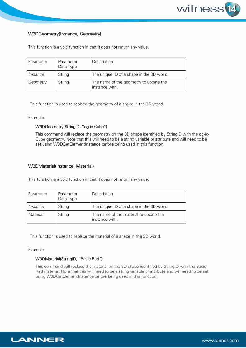
W3DGeometry(Instance, Geometry)
This function is a void function in that it does not return any value. Parameter Parameter
Data Type Description
Instance String The unique ID of a shape in the 3D world
Geometry String The name of the geometry to update the
instance with.
This function is used to replace the geometry of a shape in the 3D world.
Example
W3DGeometry(StringID, “dg-ic-Cube”) This command will replace the geometry on the 3D shape identified by StringID with the dg-ic-
Cube geometry. Note that this will need to be a string variable or attribute and will need to be
set using W3DGetElementInstance before being used in this function.
W3DMaterial(Instance, Material)
This function is a void function in that it does not return any value. Parameter Parameter
Data Type Description
Instance String The unique ID of a shape in the 3D world
Material String The name of the material to update the
instance with.
This function is used to replace the material of a shape in the 3D world.
Example
W3DMaterial(StringID, “Basic Red”) This command will replace the material on the 3D shape identified by StringID with the Basic
Red material. Note that this will need to be a string variable or attribute and will need to be set
using W3DGetElementInstance before being used in this function.
Changes to WITNESS Floating Point operations
WITNESS 14 is built using Microsoft Visual Studio 2013 to take advantage of new and enhanced
features. This has allowed the use of a more precise option for floating point calculations. In
comprehensive testing there are some very small differences in calculations, in the magnitude of 10-6
and smaller.
The vast majority of models will be completely unaffected by this, but where calculations are to many
decimal places and where logic has been constructed that takes advantage of tiny numerical
differences then changes to the results of models may be observed.