with dual expansion peek anchor and bone socket xation · to the biceps tendon, other causes of...
TRANSCRIPT
237
30Arthroscopic suprapectoral biceps tenodesis with dual expansion PEEK anchor and bone socket fixation
JOSEPH C. TAURO and JONATHAN B. TICKER
INTRODUCTION AND INDICATIONS
Pathology of the long head of the biceps (LHB) is a com-mon cause of shoulder pain.1–3 Aside from direct damage to the biceps tendon, other causes of biceps pain include tears of the superior labrum (SLAP lesions) and lesions of the biceps pulley and upper subscapularis, which can result in bicipital instability.
Initial management of LHB pathologies usually includes rest, non-steroidal anti-inflammatory drugs, physical ther-apy, and corticosteroid injection. If conservative measures fail, the main surgical options employed are tenotomy and tenodesis. Tenotomy has long been regarded as a simple solution to pain associated with tendinopathy. However, patients who undergo tenotomy may subsequently experi-ence retraction of the biceps tendon and cramping of the brachial biceps muscle.4
Tenodesis has been shown to have similar relief of pain as tenotomy, and better functional performance in some studies.5,6 The most definitive advantage of tenodesis over tenotomy is a much lower incidence of inferior migra-tion of the biceps, the “Popeye” deformity.2 Furthermore, tenodesis may improve long-term function because it better restores normal anatomy.7 Our indications for tenodesis include chronic tendonitis, partial or complete tears of the LHB, SLAP lesions in older patients, or failed SLAP repairs and tendon subluxation out of the bicipital
groove in active patients who have failed conservative management.
Interference screws commonly used for tenodesis have been shown to have higher ultimate load to failure and improved stiffness compared to suture anchors, although, these devices may have a higher revision rate due to rup-ture of the tendon at site of tenodesis.8,9 It is believed that the failures of these devices are due, in part, to trauma to the tendon during fixation. It is postulated that screw threads can cause rotation of the graft, decreased restored tension, and a reduced load to failure. Recent ex vivo models have demonstrated that use of sheathed screws can decrease malrotation of screws and trauma to tendon during tenodesis.8 In addition to tendon rupture, subpec-toral tenodesis with an interference screw can be associ-ated with humerus fracture at the site of placement.10 Interference screw placement has been shown to decrease humeral strength by up to 25% in some models.11 To our knowledge there is no known association of humerus frac-ture associated with suprapectoral methods. Compared to biceps tenodesis at the superior margin of the bicipi-tal groove, there is less chance of impingement on the acromial roof, persistent instability, or leaving residual diseased tendon with a tenodesis at the inferior margin. For all of these reasons, we prefer arthroscopic suprapec-toral biceps tenodesis using a non-threaded implant, as described in this chapter.
CONTENTS
Introduction and indications 237Diagnosis and preoperative assessment 238Strategy and preoperative counseling 238Operative technique 238Postoperative protocol 242Tips, tricks, and pearls 243References 243
238 Arthroscopic suprapectoral biceps tenodesis with dual expansion PEEK anchor and bone socket fixation
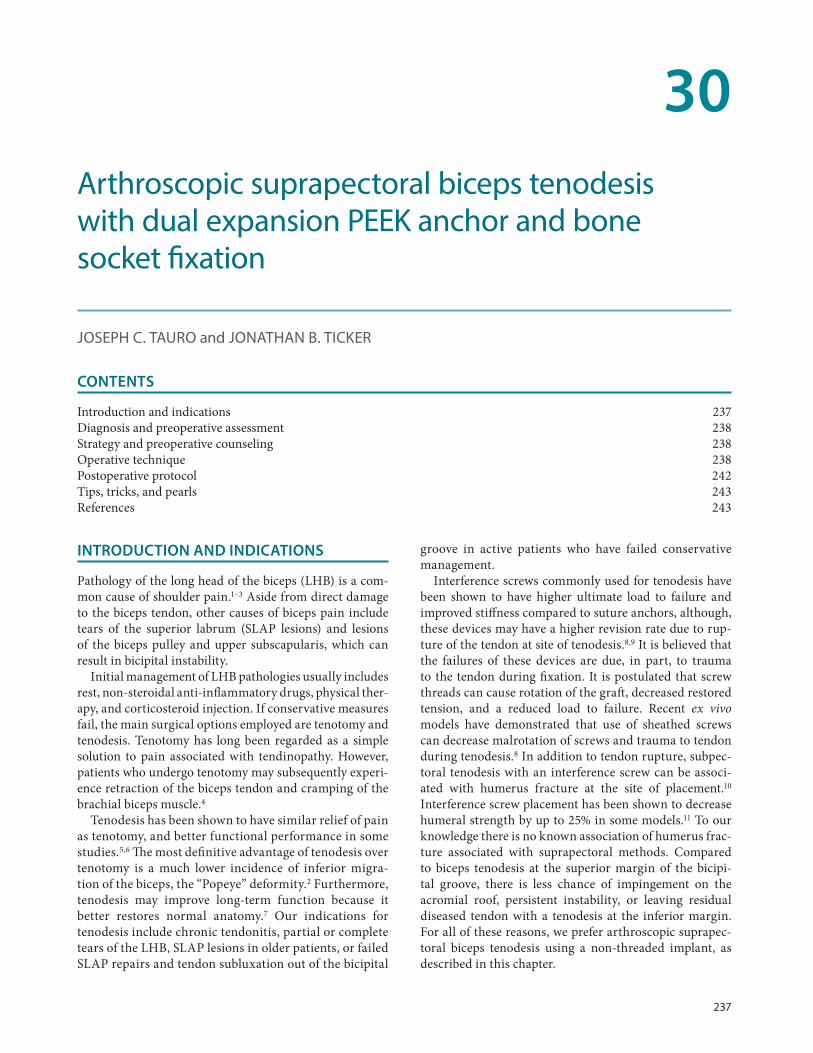
For the arthroscopic biceps tenodesis technique pre-sented in the suprapectoral location, a dual-expanding anchor is utilized. The Tenolok (ConMed, Largo, FL) is designed to provide tendon-to-bone fixation, with both secure cortical and subcortical engagement in bone (Figure 30.1). The method of deployment, by straight insertion and expansion, reduces tendon damage and tendon wrap com-pared with interference screw usage. The anchor is 17 mm in height, and comes in a diameter of 5 mm or 6 mm. Once fully deployed, the 5 mm anchor is 14 mm in height, with a width of 6.5 mm at the cortex and 8 mm subcortical. The 6 mm anchor also becomes 14 mm in height, though with a width of 7.5 mm at the cortex and 10 mm subcortical.
DIAGNOSIS AND PREOPERATIVE ASSESSMENT
The clinical assessment for a patient with suspected biceps pathology includes a directed history of the shoul-der complaints, current levels of pain and functional limitations as a result of the complaints, and any treat-ment rendered thus far. The directed physical exami-nation should assess visually for normal or abnormal position of the biceps muscle. Palpation for tenderness along the long head of the biceps tendon especially at the bicipital groove, testing for pathology of the biceps and at the superior labrum, and assessment for involvement of the subscapularis and the supraspinatus are important components of the exam. Palpable clicking anteriorly or a positive Speed’s or Yergason’s test may also support a diagnosis of biceps tendon pathology and/or instability.
While radiographs are less helpful to detect biceps pathol-ogy, the quality of the bone about the bicipital groove and proximal humerus should be assessed. Magnetic resonance imaging (MRI) is very helpful to visualize any soft-tissue and bony pathology present, including biceps tendon abnormalities, position, and fluid, in addition to viewing associated pathology, such as with the rotator cuff tendons. When the biceps is subluxed or dislocated medially, a biceps pulley lesion and subscapularis tendon pathology must always be suspected. In the setting of biceps tendinitis, a diagnostic (and potentially therapeu-tic) injection can be helpful, though this approach is not expected to provide long-term benefits when the biceps is unstable.
STRATEGY AND PREOPERATIVE COUNSELING
When biceps tenodesis is indicated, the technique described in this chapter is useful in a myriad of circum-stances. However, the strategy for using this technique for isolated superior labral or biceps tendon pathology will differ somewhat from the strategy when any associ-ated pathology, such as a subscapularis tear, an antero-superior rotator cuff tear, or posterosuperior rotator cuff tear, is present. This is mainly in the sequence of steps utilized. The technique below will describe the steps for treatment of isolated long head of biceps tendon pathol-ogy. Even in these circumstances, there should be a high index of suspicion for the possibility of hidden lesions in the bicipital groove.12 The preoperative discussion with the patient includes a review of the perioperative course and pain management, the healing process and timing, the required period of immobilization, the initial limitations with activities of daily living, and the rehabilitation pro-tocol, as important components. Informed consent, more specific for a biceps tenodesis, includes a discussion of infection, failure, bleeding, stiffness, pain, fracture, hard-ware failure, neurovascular compromise, and deformity, among other aspects.
OPERATIVE TECHNIQUE
Anesthesia includes an interscalene block, unless con-traindicated, and usually a general anesthetic with a laryngeal mask airway or, less often, endotracheal intu-bation. The body position can be in the lateral decubitus or beach-chair alignment, with all down surfaces padded. After sterile preparation and draping from the midline and above the nipple to expose the entire shoulder, bony landmarks are drawn. Portal placement is also marked to include standard posterior, lateral, and anterior portals. In addition, a direct bicipital portal is drawn in an approxi-mate position with palpation of the biceps groove with the arm in a neutral position.
Figure 30.1 The Tenolok anchor, undeployed on the left and deployed on the right, with distal suture loop for encir-cling the biceps tendon.
Operative technique 239
For the diagnostic glenohumeral arthroscopy, a stan-dard posterior viewing portal (PP) and an anterior work-ing portal (AP) are utilized to confirm the pathology to the biceps tendon. Spinal needles are used to mark the biceps groove from outside-in for later localization in the subacromial space. When the needle is brought into the joint tangential to the superior surface of the humeral head, this can serve to mark approximately the upper-most position of the biceps groove. If desired, two spinal needles can be used to mark the posterior and the ante-rior aspects of the proximal groove, like goal posts, to guide identification of the groove later on (Figure 30.2). It is preferred to keep the biceps tendon attached at this time to maintain the in-situ length of the biceps tendon to better recreate this length–tension relationship after the final tenodesis construct is completed. Alternatively, the biceps tendon can be stabilized by the spinal needles to maintain the resting length of the biceps, and the ten-don is then detached from its insertion at the superior glenoid tubercle.
In the subacromial space, a standard lateral portal (LP) is created, though in a slightly more anterior position to maximize visualization of the biceps tendon and the entire bicipital groove to the suprapectoral region. A shaver from the AP or LP clears any bursa obscuring the spinal needle, or needles (Figure 30.3). Viewing from the LP, a probe or blunt trocar from the AP is used to determine the location and course of the bicipital groove, which is usually more vertical and, thus, less oblique than might be considered. It is useful to palpate the lateral edge of the lesser tuberos-ity from proximal to distal. Once the groove position is determined and the overlying intertubercular ligament is exposed, a direct bicipital portal (DBP) is created. A spinal needle is brought in from an anterolateral location along the bicipital groove to localize portal position. This portal should be in a more distal location as it will be used for
creating the bone hole socket and inserting the Tenolok anchor approximately perpendicular to the humerus at the inferior portion of the groove into the suprapectoral region.
The intertubercular ligament can be incised sharply with an arthroscopic knife or a cautery device (Figure 30.4). After the initial exposure of the tendon, the course of the bicipital groove is again confirmed. The ligament is further incised distal to the tuberosity and proximal, as needed, for exposure, though it is usually not necessary to expose to the level of the articular surface (Figure 30.5). As the biceps is stabilized by its still-intact attachment at the superior glenoid tubercle or by a spinal needle, a probe from the anterior portal is used to gently reflect the biceps tendon anterior to visualize the floor of the bicipi-tal groove, the prominence of the lesser tuberosity, and further distal to the prominence. The location for socket
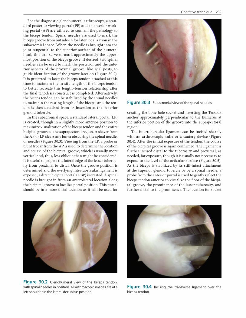
Figure 30.2 Glenohumeral view of the biceps tendon, with spinal needles in position. All arthroscopic images are of a left shoulder in the lateral decubitus position.
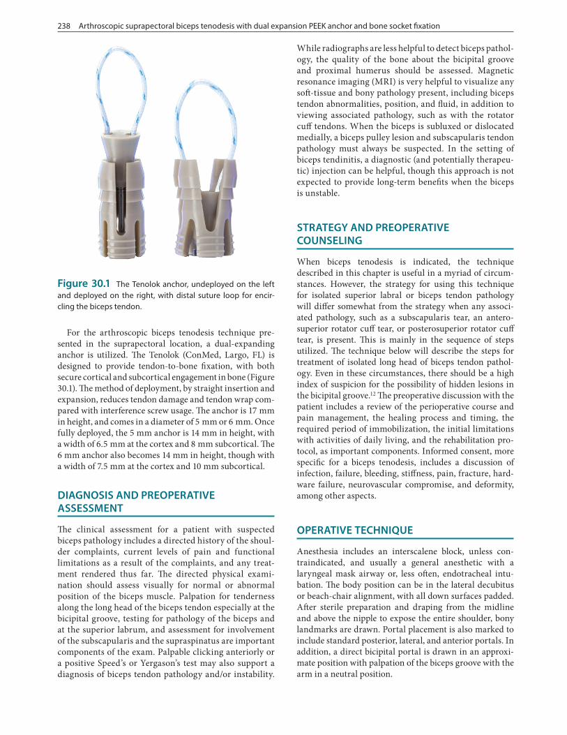
Figure 30.3 Subacromial view of the spinal needles.
Figure 30.4 Incising the transverse ligament over the biceps tendon.
240 Arthroscopic suprapectoral biceps tenodesis with dual expansion PEEK anchor and bone socket fixation
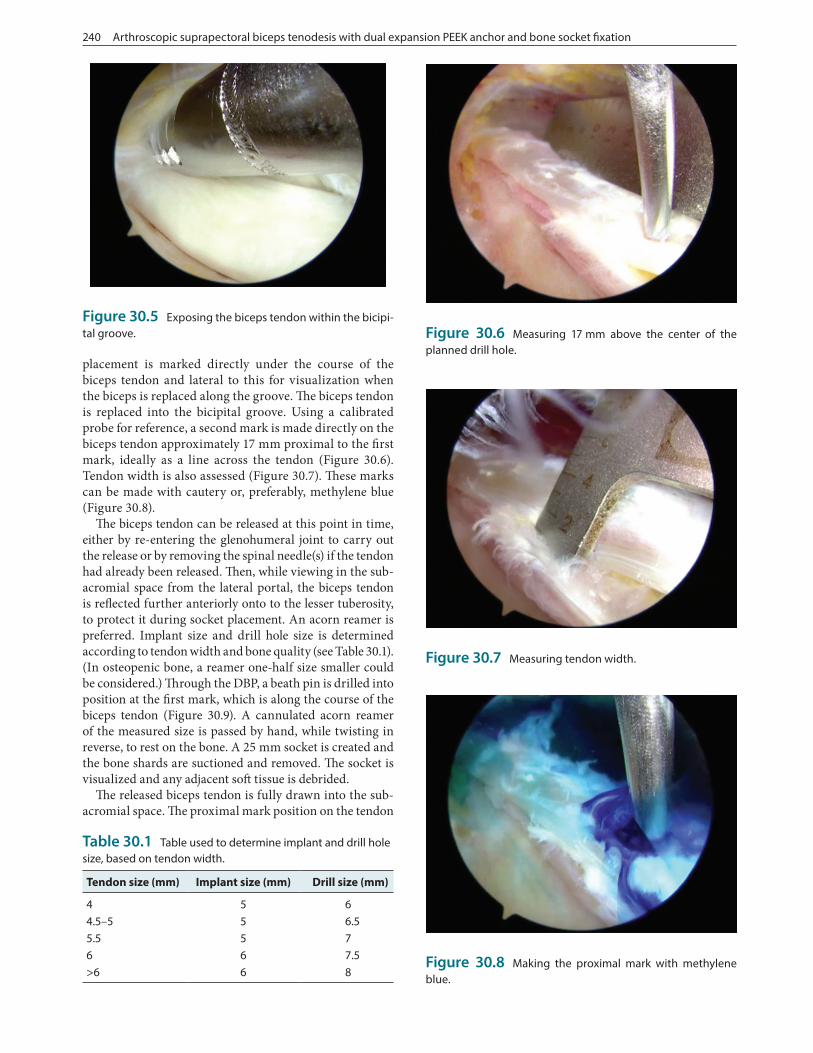
placement is marked directly under the course of the biceps tendon and lateral to this for visualization when the biceps is replaced along the groove. The biceps tendon is replaced into the bicipital groove. Using a calibrated probe for reference, a second mark is made directly on the biceps tendon approximately 17 mm proximal to the first mark, ideally as a line across the tendon (Figure 30.6). Tendon width is also assessed (Figure 30.7). These marks can be made with cautery or, preferably, methylene blue (Figure 30.8).
The biceps tendon can be released at this point in time, either by re-entering the glenohumeral joint to carry out the release or by removing the spinal needle(s) if the tendon had already been released. Then, while viewing in the sub-acromial space from the lateral portal, the biceps tendon is reflected further anteriorly onto to the lesser tuberosity, to protect it during socket placement. An acorn reamer is preferred. Implant size and drill hole size is determined according to tendon width and bone quality (see Table 30.1). (In osteopenic bone, a reamer one-half size smaller could be considered.) Through the DBP, a beath pin is drilled into position at the first mark, which is along the course of the biceps tendon (Figure 30.9). A cannulated acorn reamer of the measured size is passed by hand, while twisting in reverse, to rest on the bone. A 25 mm socket is created and the bone shards are suctioned and removed. The socket is visualized and any adjacent soft tissue is debrided.
The released biceps tendon is fully drawn into the sub-acromial space. The proximal mark position on the tendon
Figure 30.5 Exposing the biceps tendon within the bicipi-tal groove.
Figure 30.7 Measuring tendon width.
Table 30.1 Table used to determine implant and drill hole size, based on tendon width.
Tendon size (mm) Implant size (mm) Drill size (mm)
4 5 64.5–5 5 6.55.5 5 76 6 7.5>6 6 8
Figure 30.6 Measuring 17 mm above the center of the planned drill hole.
Figure 30.8 Making the proximal mark with methylene blue.

Operative technique 241
is reconfirmed. From the AP, the tendon is secured by a grasper about 10–15 mm from the proximal cut end. Through the DBP, the Tenolok, with its distal suture loop expended, is introduced into the subacromial space. Using a probe or retriever from the PP, the suture loop at the end of the device is drawn to a position approximately over the supraspinatus. The proximal biceps stump is brought into the suture loop, so that the loop is entirely around the ten-don (Figure 30.10). A second grasper passed through the PP secures the very end of the biceps, and the first grasper is released. Alternatively, with the enlarged suture loop approximately located over the supraspinatus, the second grasper is passed though the loop and secures the very end of the biceps. The first grasper is removed and the loop is brought around the entire tendon. Either way, the suture loop is then brought to the 17 mm proximal mark on the biceps tendon, and the loop is securely tightened around the biceps. The suture limbs exiting the handle are secured at the end of the handle to maintain the tendon securely under the bottom of the Tenolok anchor.
By maneuvering the inserter handle of the Tenolok, the end of the device with the tendon and tight suture loop is placed over the bone socket (Figure 30.11). The Tenolok with biceps tendon is introduced into the socket. A mallet is used to impact at the top of the handle to insert the tendon and device in stages, until the laser line and top of the implant is at the cortical level of the bone socket. While holding the device/tendon construct in the hole, the main part of the handle is firmly held to prevent rotation. The knob at the top of the inserter handle is twisted clockwise until a snap is felt and heard, creating the dual radial expansion which secures the tendon within the bone socket. The sutures are then released from the insertion handle. The handle is then removed from the DBP, and traction is placed on the suture limbs to confirm secure fixation of the Tenolok and tendon within the bone socket. The construct is probed to insure security. The suture is usually removed, though it can be tied with multiple half-hitches into the center of the Tenolok and/or passed through the tendon and then tied with multiple half-hitches. The construct can be visualized through the DBP, in addition to the LP (Figure 30.12). The proximal stump of biceps is trimmed to be approximately 5 mm from the bone.
Following completion of the shoulder arthroscopy, the portals are closed and dressings are applied. The arm is immobilized in a sling or cryocompression unit. The patient is discharged home in the ambulatory setting with pain medication. The first follow-up visit is about 6–10 days post-op for suture removal, review of the surgical repair, and rehabilitation planning. The sling is main-tained for 6 weeks, about when the next post-op visit occurs. The patient continues with the rehabilitation pro-cess and is seen around 3 months post-op. Additional vis-its at 4½ months and 6 months post-op may be scheduled. Return to work can ensue within 7–10 days for a sedentary job, such as a desk worker. A manual laborer with a heavy-duty job may be out of work 3 months or more, especially if there is no temporary light-duty alternative. A patient
Figure 30.9 Placement of the beath pin in the suprapec-toral position.
Figure 30.10 Encircling the biceps tendon with the distal suture loop.
Figure 30.11 Placing the biceps tendon, secured to the anchor by the tightened loop, at the drill hole. The grasper from the posterior portal is seen, stabilizing the proximal tendon.

242 Arthroscopic suprapectoral biceps tenodesis with dual expansion PEEK anchor and bone socket fixation
with a light-duty job may return to work within weeks after surgery, with the caveat to avoid shoulder extension past neutral, active elbow flexion and forearm supination, as well as lifting, pushing, pulling, and carrying. In the dominant arm of an overhead athlete, as a general guide-line, sport-specific progression usually begins at 4 months and continues at least until 6 months, when repair strength and coordination have reached adequate levels.
POSTOPERATIVE PROTOCOL
The rehabilitation protocol we follow for an isolated biceps tenodesis, as a general guideline, is listed below. The initia-tion of physical therapy and the exact timing of progres-sion during the rehabilitation process may vary, taking into account circumstances for any individual patient. For clar-ification, the time periods below refers to the 7 days of the particular week. As examples, post-op week 1 includes days 1–7 and post-op week 7 includes days 43–49. The rehabili-tation continues for the time necessary for each individual patient to recover and return to his or her desired activities.
Post-op week 1
• Pendulums• Gentle pain-free PROM for forward elevation and external rotation• Supine AAROM external rotation with stick. Shoulder at 30°–45° of abduction and arm at least level with abdo-men (use towel roll/pillow)• Self supine AAROM forward elevation• Wrist and hand AROM/gripping• Pain and edema modalities (ice, electrical stimulation)• Avoid shoulder extension past neutral (use towel roll/pillow under elbow in supine), active elbow flexion and forearm supination, IR beyond stomach, lifting, push-ing, pulling, carrying, AROM, and sleeping on the involved side
Post-op week 2
• Pendulums• Elbow PROM• Continue with shoulder PROM and AAROM exercises• Continue wrist/hand AROM/gripping• Pain and edema modalities (ice, electrical stimulation)• Avoid shoulder extension past neutral, active elbow flexion and forearm supination, IR beyond stomach, lifting, pushing, pulling, carrying, AROM, and sleeping on the involved side
Post-op weeks 3–4
• PROM and AAROM exercises as tolerated• Continue elbow PROM, wrist/hand AROM/gripping• Pulley in scapula plane with quality ROM (no scapula hike), if pain, hold off• Pain-free sub-maximal isometrics except shoulder flex-ion and elbow flexion• Prone row, extension to neutral (no weight)• AROM side-lying ER/IR (no weight)• Scapula control exercise by PT in side-lying: active-assisted/active/resistive (to begin to restore scapula sta-bility/force couple)• Modalities for pain• Continue to avoid shoulder extension past neutral, active elbow flexion and forearm supination, lifting, pushing, pulling, carrying, and sleeping on the involved side
Post-op weeks 5–6
• Achieve full PROM all planes• Initiate AROM forward elevation in the scapula plane beginning with gravity eliminated positions (supine and side-lying) and progress according to quality of motion (semi-recumbent, sitting and/or standing); avoid scapula hiking and begin with elbow flexed (short lever arm) and progress to elbow extended• Glenohumeral stabilization and rhythmic stabiliza-tion exercises in supine for forward elevation, IR/ER (to restore neuromuscular control and proprioception needed for dynamic stability of GH joint)• Continue weeks 3–4 program• Avoid active elbow flexion and supination and maintain lifting restrictions
Post-op week 7
• Begin AROM elbow flexion and forearm supination• Active forward elevation with thumb-up, “full can” position and progressed to resisted with light dumbbell/band when normal AROM has been achieved without substitution/scapula hike
Figure 30.12 Fully deployed anchor within bone socket.
References 243
• Initiate light resistance if normal AROM in these planes without abnormal or substituted movement patterns; start with 1 lb. dumbbell and elastic band/tubing with least resistance:• Side-lying ER/IR• Prone extension/row• Scapula protraction supine• Elastic band/tubing for ER, IR, extension to neu-
tral, scapula retraction and when ready scapula punches/dynamic hug standing• Begin light triceps strengthening• Progress scapula stabilization exercises
Post-op weeks 8–9
• Begin light strengthening of biceps if no symptoms with active elbow flexion• UBE• Stretch posterior shoulder/capsule (sleeper stretch)• Begin closed chain exercises• Continue PROM/AAROM exercises all planes as needed all planes• Progress strengthening program• Begin appropriate PNF patterns
Post-op weeks 10–11
• Progress open and closed chain exercises as appropriate• Maintain PROM and flexibility• Begin light functional activity as appropriate and within surgeon’s guidelines
• Return-to-work considerations• Sport-specific activity/plyometrics
TIPS, TRICKS, AND PEARLS
With this technique, the dual-expansion of the anchor with dual-compression of the tendon within the bone socket provides secure tendon fixation for biceps tenodesis. The technique also allows for maintaining the length–tension relationship of the biceps tendon.13 The approach to mea-sure the tendon with respect to the planned bone socket, with the tendon either still attached at the superior glenoid tubercle or maintained in this native position by a spinal needle, allows for recreation of the length– tension rela-tionship of the biceps tendon after it is tenodesed. Initial exposure of the biceps tendon in the bicipital groove does take some practice to insure accurate incising of the inter-tubercular ligament.14 To improve viewing into the groove, portions of the incised ligament can be ablated with a wand or debrided with a shaver. When using a shaver, especially more distally, ascending and crossing bleeders must be anticipated and cauterized once encountered to maintain
visualization. When directing the Tenolok with secured tendon to the bone socket, maintaining the grasper on the proximal tendon end helps maintain the tendon fully under the implant. This technique can be used equally well in the beach-chair or lateral decubitus positions.
REFERENCES
1. Abraham VT, Tan BH, Kumar VP. Systematic review of biceps tenodesis: Arthroscopic versus open. Arthroscopy 2016;32(2):365–371.
2. Levy DM et al. Subpectoral biceps tenodesis. Am J Orthop (Belle Mead NJ) 2016;45(2):68–74.
3. Werner BC et al. Trends in long head biceps tenode-sis. Am J Sports Med 2015;43(3):570–578.
4. Galasso O et al. Tenotomy versus tenodesis in the treatment of the long head of biceps brachii tendon lesions. BMC Musculoskelet Disord 2012;13:205.
5. Rose GD et al. The long head of biceps as a source of pain in active population: Tenotomy or tenodesis? A comparison of 2 case series with isolated lesions. Musculoskelet Surg 2012;6(Suppl 1):S47–S52.
6. Slenker NR et al. Biceps tenotomy versus tenodesis: Clinical outcomes. Arthroscopy 2012;28(4):576–582.
7. Hsu AR et al. Biceps tenotomy versus tenodesis: A review of clinical outcomes and biomechanical results. J Shoulder Elbow Surg 2011;20(2):326–332.
8. Saithna A et al. An analysis of the biomechanics of interference screw fixation and sheathed devices for biceps tenodesis. Clin Biomech (Bristol) 2015;30(6): 551–557.
9. Koch BS, Burks RT. Failure of biceps tenodesis with interference screw fixation. Case report. Arthroscopy 2012;28(5):735–740.
10. Beason DP et al. Torsional fracture of the humerus after subpectoral biceps tenodesis with an interference screw: A biomechanical cadaveric study. Clin Biomech (Bristol) 2015;30(9):915–920.
11. Euler SA et al. Biomechanical analysis of subpecto-ral biceps tenodesis: Effect of screw malpositioning on proximal humeral strength. Am J Sports Med 2015;43(1):69–74.
12. Moon SC, Cho NS, Rhee YG. Analysis of “Hidden Lesions” of the extra-articular biceps after subpec-toral biceps tenodesis: The subpectoral portion as the optimal tenodesis site. Am J Sports Med 2015; 43:63–68.
13. Werner BC et al. Arthroscopic suprapectoral and open subpectoral biceps tenodesis: A compari-son of restoration of length-tension and mechani-cal strength between techniques. Arthroscopy 2015;31(4):620–627.
14. Shen J et al. Arthroscopic tenodesis through posi-tioning portals to treat proximal lesions of the biceps tendon. Cell Biochem Biophys 2014;70(3):1499–1506.
