with analysis model - welcome to software testing and...
TRANSCRIPT

Software
Requirements
Specification
with
Analysis Model
Last Revision: 20150505
TEAM 5
◇ Han, Sumin
● Oh, Joonhoo
*Responsibility is denoted by ◇(Sumin Han), and ●(Joonhoo Oh)

Last Revision: 20150505 SAFEHOME TEAM 5
Page 1
Contents A. Project Overview .............................................................................................................................. 4
A.1. Introduction ◇ ......................................................................................................................... 4
A.2. Main target for this document ◇ .............................................................................................. 4
A.3. Responsibility ◇● .................................................................................................................... 4
B. SafeHome Overview ........................................................................................................................ 5
B.1. Assumptions for SafeHome project ◇ ..................................................................................... 5
B.2. SafeHome Units ◇ .................................................................................................................. 6
B.3. Information ◇ .......................................................................................................................... 7
B.4. Motion direction and speed ◇ ................................................................................................. 8
B.5. Security Zone ◇ ...................................................................................................................... 8
B.6. Use-case Overview ◇● ......................................................................................................... 10
C. Use cases ...................................................................................................................................... 11
C.1. Boot ..................................................................................................................................... 11
C.1.1. Boot-up (CP) ● ........................................................................................................... 11
C.1.2. Shutdown (CP) ● ........................................................................................................ 12
C.1.3. Initialize Sensors ● ..................................................................................................... 13
C.1.4. Initialize Cameras ● ................................................................................................... 14
C.1.5. Finish Sensors ● ........................................................................................................ 14
C.1.6. Finish Cameras ● ....................................................................................................... 15
C.2. Configure ............................................................................................................................. 17
C.2.1. Setting Main (Web) ◇ ................................................................................................. 17
C.2.2. Setting Sensors (Web) ◇ ............................................................................................ 18
C.2.3. Setting Cameras (Web) ◇ ........................................................................................... 19
C.2.4. Setting Cameras Detail (Web) ◇ ................................................................................. 19
C.2.5. Setting Options (Web) ◇ ............................................................................................. 20
C.2.6. Weekly Mail Report ● ................................................................................................. 21
C.2.7. Self-Diagnosis ● ......................................................................................................... 22
C.3. User Management ................................................................................................................ 23
C.3.1. Login (Web) ◇ ............................................................................................................ 23
C.3.2. Logout (Web) ◇ .......................................................................................................... 24
C.3.3. User Log (Web) ◇ ....................................................................................................... 25
C.3.4. User Create (Web) ◇ .................................................................................................. 26

Last Revision: 20150505 SAFEHOME TEAM 5
Page 2
C.3.5. User edit (Web) ◇ ....................................................................................................... 26
C.3.6. Finding ID/Password (Web) ◇ .................................................................................... 28
C.4. Arm/Disarm .......................................................................................................................... 30
C.4.1. Arm System via Control Panel (CP) ● ........................................................................ 30
C.4.2. Disarm System via Control Panel (CP) ● .................................................................... 31
C.4.3. Arm System via Internet (Web) ◇ ............................................................................... 33
C.4.4. Disarm System via Internet (Web) ◇ ........................................................................... 34
C.4.5. Auto Arm System ◇● .................................................................................................. 35
C.4.6. Overnight Travel Mode (Web) ◇● ............................................................................... 36
C.4.7. Extended Travel Mode (Web) ◇● ............................................................................... 36
C.5. Intruder Prevention System .................................................................................................. 38
C.5.1. Intruder detection ◇ .................................................................................................... 39
C.5.2. Intrude Trial Detection ◇ ............................................................................................. 40
C.5.3. Possilbe Intruder Alarm ◇ ........................................................................................... 41
C.6. Home Management .............................................................................................................. 43
C.6.1. Fire Alarm ● ............................................................................................................... 43
C.6.2. Gas Alarm ● ............................................................................................................... 44
C.6.3. Water Level Abnormality Alarm ● ............................................................................... 46
C.6.4. Doggie Angust Alarm ● .............................................................................................. 47
C.6.5. Display Sensor Data ● ............................................................................................... 48
C.6.6. Control Appliances/Lightning/HVAC via Internet (Web) ◇ ........................................... 49
C.7. Home Surveillance ............................................................................................................... 51
C.7.1. Temporary Camera Control (Web) ◇ .......................................................................... 52
C.7.2. Camera Overview (Web) ◇ ......................................................................................... 54
C.7.3. Camera Detail (Web) ◇ .............................................................................................. 55
C.7.4. Camera Record ◇ ....................................................................................................... 56
C.7.5. Create Camera thumbnail ◇ ....................................................................................... 57
C.7.6. Play recorded video ◇ ................................................................................................ 58
C.8. Non-Functional Use Cases .................................................................................................. 59
C.8.1. Telephone Call Control ● ........................................................................................... 59
C.8.2. Extra Power Supply ●................................................................................................. 61
C.8.3. Session Timeout ◇ ..................................................................................................... 63
C.8.4. Multiple Access Control ◇●......................................................................................... 65
D. GUI for SafeHome Web Service ..................................................................................................... 67

Last Revision: 20150505 SAFEHOME TEAM 5
Page 3
E. Glossary ●◇ .................................................................................................................................... 74
F. Traceability Matrix ●◇ ..................................................................................................................... 75
Figure Index
Figure-B-1. System Deployment Diagram ◇ (page 5)
Figure-B-2. Control Panel ◇● (page 6)
Figure-B-3. Floor Plan with the locations of the sensors and the cameras ◇● (page 8)
Figure-C-1. Swimlane diagram for Boot-up via Control Panel ● (page 11)
Figure-C-2. Swimlane diagram for Shutdown via Control Panel ● (page 12)
Figure-C-3. Swimlane diagram for Setting Configuration ◇ (page 17)
Figure-C-4. Swimlane diagram for Login at Web Service ◇ (page 23)
Figure-C-5. Swimlane diagram for Logout at Web Service ◇ (page 24)
Figure-C-6. Swimlane diagram for Finding ID/Password in Web Service ◇ (page 28)
Figure-C-7. Swimlane diagram for Arm System via Control Panel ● (page 30)
Figure-C-8. Swimlane diagram for Disarm System via Control Panel ● (page 32)
Figure-C-9. Swimlane diagram for Arm System via Internet ◇ (page 33)
Figure-C-10. Swimlane diagram for Disarm System via Internet ◇ (page 35)
Figure-C-11. Usecase diagram for Inturder Prevention System ◇ (page 39)
Figure-C-12. Swimlane diagram for Intruder Detection ◇ (page 40)
Figure-C-13. Swimlane diagram for Intrude Trial Detection ◇ (page 41)
Figure-C-14. Swimlane diagram for Possilbe Intruder Alarm ◇ (page 42)
Figure-C-15. Usecase diagram for Home Management ● (page 44)
Figure-C-16. Usecase diagram for Control Appliances/Lightning/HVAC ◇ (page 50)
Figure-C-17. Usecase diagram for Home Surveillance ◇ (page 52)
Figure-C-18. Swimlane diagram for Home Surveillance ◇ (page 53)
Figure-C-19. Swimlane diagram for Telephone Call Control ● (page 60)
Figure-C-20. Swimlane diagram for Extra Power Supply ● (page 62)
Figure-C-21. Swimlane diagram for Session Timeout ◇ (page 64)
Figure-C-22. Swimlane diagram for Multiple Access Control ◇● (page 66)
GUI-Figure-1. Web Service Login ◇ (page 68)
GUI-Figure-2. Main Menu ◇ (page 68)
GUI-Figure-3. User View ◇ (page 69)
GUI-Figure-4. User Create New Account ◇ (page 69)
GUI-Figure-5. User Log ◇ (page 70)
GUI-Figure-6. User Edit Account and their authority ◇ (page 70)
GUI-Figure-7. Camera thumbnails with flood plan and detection log. ◇ (page 71)
GUI-Figure-8. When click into camera detail ◇ (page 71)
GUI-Figure-9. Sensor Data Display ◇ (page 72)
GUI-Figure-10. Data Log for each sensor ● (page 72)
GUI-Figure-11. Settings ● (page 73)
GUI-Figure-12. Camera Settings ◇ (page 74)

Last Revision: 20150505 SAFEHOME TEAM 5
Page 4
A. Project Overview
A.1. Introduction ◇
SafeHome is automated system which enables users to surveil home anytime anywhere when
the user is inside thorugh control panel or outside through the internet. In addition, user can access to
some of the functions and control their behaviors. If there’s any abnormal event such as intruder
detection via camera, CO level change via CO sensor and water level via water level sensor. In these
cases, user will be notified through message that has been sent from SafeHome System.
In this document, we separated core functions into two main stream. First one is control panel
which is already installed in house. Another is SafeHome web service which lets users to control or
surveil through internet. Fundamentally, The SafeHome server is installed in the house. This main
server opens https protocol (443) for the users outside to access through web service with information
encryption using SSH layer.
Moreover, concurrent multiple requests is not allowed. If there is case, the former logged in
user gets priority. However, using control panel can take away the priority from web user. The usecase
for multiple access control is explained in C.8.4. Multiple Access Control.
Efficient use of camera recording is also important. Safehome camera will record only when
there is event. The detection of change is conducted by comparing the default image with the current
image. The default image is taken every 10 minutes automatically, and this image is also used as
thumbnail after make into smaller size. The comparing function is done by calculating sum of the
distances of the rgb value of each pixel.
SafeHome also provides automatic report to user by message when there is abnormal event
such as appearance of intruder or sensor alarm. If user does not respond for set time period,
SafeHome calls the fire station and the police station.
Finally SafeHome also have overall reporting service through e-mail. After collecting data such
as user logs or suspicious behaviors, it combines and report to the each user. These are the main
activities that SafeHome supports, and user will be satisfied with secure home.
A.2. Main target for this document ◇
This documents is intended to share information for the programmers, project managers,
designers, and testers. This document contains both internal systems and behaviors of SafeHome
systems, functionality, and designs including floor plan GUI and control panels. This document also
considered security issues such as SSH layer or RSA encryption of password for suggestion.
A.3. Responsibility ◇●
The authorship information for the work product in this document is denoted as ●(Joonhoo Oh)
and ◇(Sumin Han) for accountability and maintainability.

Last Revision: 20150505 SAFEHOME TEAM 5
Page 5
B. SafeHome Overview
Figure-B-1. System Deployment Diagram ◇
B.1. Assumptions for SafeHome project ◇
1. No concurrent user accesses. e.g.
a. Access through a control panel and access through a web page are exclusive; both
cannot happen at the same time.
b. Only one control panel is installed in a house
c. Control panel gets higher priority than web user. Control panel can force to logout
previous logged in web user.
2. Internet connection between a homeowner (i.e., homeowner’s smartphone or notebook) and
the SafeHome system is always available.
3. All devices including cameras, sensors, and the SafeHome main system communicate using
IEEE 802.11x

Last Revision: 20150505 SAFEHOME TEAM 5
Page 6
B.2. SafeHome Units ◇
1. SafeHome Main Server
:Controls entire functionalities: 1. Control panel and Web Service, 2. Alarm or automatic call,
and message report system, 3. Settings and User DB which can only be accessed by admin, 4.
Sensors and Camera Unit which detects actual abnormality.
2. Control Software
: Mostly related to the direct control with sensors and cameras. Also include devices that are
connected wirless using IEEE 802.11b standard. Control Software takes care of internal
system. Control Software also includes ARS system(SEE: C.8.1. Telephone phone call) and
Extra battery(SEE: C.8.2. Extra Power Supply) for non-functional usecases.
3. Control Panel
: Control panel is installed only one inside house. To use functions via Control Panel, it only
requires 4-digit numbered password. It can take off power from logged in Web User. Since
control panel is connected with wireless IEEE 802.11b, there’s no need for internet connection.
Figure-B-2. Control Panel ◇●
4. Web Service
: Web service enables ubiquitous access to the SafeHome main server. User must enter their
ID and passwords to be logged in. Both control panel and web user can access data though,
however, user of the control panel gets the higher authority.
: Web service runs on JRE so in order to use Web service, the computer should have JRE
installed to view on webpage.
5. User DB and Configuration
: Control panel and Web service has different port however, they share the same user DB and
settings.
6. Report system
: If there’s abnormal events, SafeHome sends message to users. The message contains url to
the SafeHome Web Service with event description. User can access to the information of
corresponding event conveniently by clicking url and check through internet. (SEE: C.6. Home
Management)
: Also every Monday, it sends weekly report to user’s mail so that user can check manually.
SEE: C.2.6. Weekly Mail Report

Last Revision: 20150505 SAFEHOME TEAM 5
Page 7
7. Alarm and automatic call
: If user does not check for the serious event such as intruder or fire in the house, it
automatically calls fire station and police station in emergent case.
8. Sensors
: There are six types of sensors: 1. Motion, 2. Window, 3. Fire, 4. CO, 5. Water Level, 6.
Doggie Angust. Each sensor can detect any abnormality if it is turned on. Admin can set their
state of on/off.
9. Camera Unit
: Camera has zoom in/out and pan functions. Home Owner can change the gaze of the camera.
When motion sensor and window sensor detects intruder or possible intruder, camera unit
starts recording automatically.
B.3. Information ◇
● Password type:
○ Control Panel: 4 digit number
○ Web Service: plain any character string with at least 8 characters.
● Password wrong
○ Basically sends SMS to Home Owner if user gets wrong more than 5 times.
● Password Encryption
○ RSA (directed encrypting algorithm)
● Web Service Security
○ SSH Layer over https protocol
● Format of recording moving picture
○ MPEG2
● Time to record video
○ maximum 1 hour for each record.
● Precondition to record
○ motion sensor and window sensors detects intruder / possible intruder
○ SEE: C.5. Intruder Prevention System and C.7.4. Camera Record
● State of Sensors
○ read
○ enable
○ disable
● Camera Function
○ record
○ play
○ controlling (zoom in/out, pan)
● State of House
○ home
○ away
○ overnight travel
○ extended travel

Last Revision: 20150505 SAFEHOME TEAM 5
Page 8
B.4. Motion direction and speed ◇
At first, motion detection is done by motion sensor. Motion sensor helps to call camera to start
recording. To calculate speed of the object, there must be some consideration to implement such
algorithm. For the basic proposal, at first let’s assume that camera takes still image every 10 minutes.
It will be treated as background image. later, current images are compared to stil limage, and each
difference in each frame will be help to calculate the speed of the object. This can be conducted by
calculation of rgb values in each frame. However, we will look for external API for safety and certainty.
B.5. Security Zone ◇
Figure-B-3. Floor Plan with the locations of the sensors and the cameras ◇●
We used 5 cameras for this floor plan. Camera 1 and 2 is gazing at window so that the camera
can detect intruder or stranger. Camera 3 is gazing kitchen to check whether there is fire. Camera 4 is
gazing at the door to see who is coming via door. Camera 5 is to check and take photos of the visitor
or stranger or intruder.

Last Revision: 20150505 SAFEHOME TEAM 5
Page 9
Also denoted locations of the sensors. W: window sensor, M: motion sensor, D: doggie angust
sensor, Gas: gas sensor, CO: CO sensor, F: Fire sensor. Motion sensor and Window sensors help
helps to detect intruder, intrude trial or possible intruder so that it calls camera to record for related
information.

Last Revision: 20150505 SAFEHOME TEAM 5
Page 10
B.6. Use-case Overview ◇●
Our team grouped use-cases into 8 big categories:
1. Boot
a. Mainly deals with central processor booting or shoutdown.
b. Use cases for the initialization and the finish of sensors and cameras are also included.
2. Configure
a. Setting of sensors, cameras, and other options are included in this category.
b. Weekly mail report and self diagnoises are considered to be regular work and they are
also included..
c. Configuration process is done via Web Service, and saves the setting value for default.
3. User Management
a. Mainly deals with Login/Logout activities.
b. Checking user logs, user create, user edit are also incuded.
c. Finding ID/password is also a big deal. It is included in this category..
4. Arm/Disarm
a. Arm/disarm events via control panel or web service are included in this category.
b. Autoarm is included.
c. Overnight travel mode or exteded travel mode are included.
5. Intruder Prevention System
a. Detection of intruder, intrude trial, possible intruder are described.
6. Home Management
a. Sensor alarms
b. Control of Appliances/Lightning/HVAC via Internet
7. Home Surveillance
a. Camera control functions such as temporal camera control, camera overview from floor
plan, record, play, thumbnails are in this category.
8. Non-Functional Use Cases
a. Telephone call, extra bettery, session timeout, multiple access control are described.

Last Revision: 20150505 SAFEHOME TEAM 5
Page 11
C. Use cases
C.1. Boot
C.1.1. Boot-up (CP) ●
Figure-C-1. Swimlane diagram for Boot-up via Control Panel ●
Use Case ID UC-1-1
Use Case Name Boot-up (CP)
Primary actor Home Owner
Goal in context Boot-up the Home Owner’s Central Processor
Preconditions Central Processor has bene shutdown.
Trigger Home Owner press the POWER button
Scenario 1. Home Owner presses the POWER button on Control Panel.
2. Safehome do UC:Initialize Sensor and UC:Initialize Camera
3. Light the Green Light labled “powered”
Exceptions
Priority High
Frequency Sometimes

Last Revision: 20150505 SAFEHOME TEAM 5
Page 12
Open issues SafeHome do not offer function to boot-up by request from Web Service.
Channel to actor
Secondary actors
C.1.2. Shutdown (CP) ●
Figure-C-2. Swimlane diagram for Shutdown via Control Panel ●
Use Case ID UC-1-2
Use Case Name Shutdown (CP)
Primary actor Home Owner
Goal in context Shutdown the Home Owner’s Central Processor

Last Revision: 20150505 SAFEHOME TEAM 5
Page 13
Preconditions System Boot-up
Trigger Home Owner presses the POWER button upto 3 seconds
Scenario 1. Home Owner presses the POWER button on Control Panel and enters
password.
2. Safehome do UC:finish Sensor and UC:finish Camera
Exceptions
Priority middle
Frequency sometimes
Open issues SafeHome do not offer function to shutdown by request from Web Service.
Channel to actor
Secondary actors
C.1.3. Initialize Sensors ●
Use Case ID UC-1-3
Use Case Name Initialize Sensors
Primary actor Control Software
Goal in context Enable and intialize the sensors.
Preconditions All of the sensors are disabled.
Trigger UC:Boot-up
Scenario 1. Home Owner pressed POWER button and the Central Processor has
been booted up.
2. Control Software restores the setting values and determines which
sensors to enable.
3. Control Software enables specific sensors from restored values(Motion
sensor, Window sensor, CO sensor, Fire sensor, Water level sensor,
Doggie Angst Sensor) and checks for the malfunction.
Exceptions 2a. If any malfunction is detected, SafeHome:Control Software notifies to Home
Owner via SMS.
Priority High
Frequency Sometimes
Open issues - How to detect the malfunction (e.g. poor connection, sensor
Last Revision: 20150505 SAFEHOME TEAM 5
Page 14
misbehave.)
Channel to actor
Secondary actors
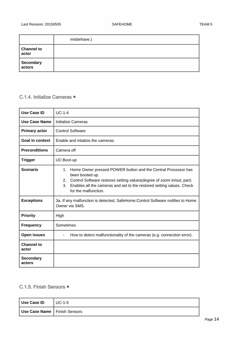
C.1.4. Initialize Cameras ●
Use Case ID UC-1-4
Use Case Name Initialize Cameras
Primary actor Control Software
Goal in context Enable and intialize the cameras.
Preconditions Camera off
Trigger UC:Boot-up
Scenario 1. Home Owner pressed POWER button and the Central Processor has
been booted up.
2. Control Software restores setting values(degree of zoom in/out, pan)
3. Enables all the cameras and set to the restored setting values. Check
for the malfunction.
Exceptions 3a. If any malfunction is detected, SafeHome:Control Software notifies to Home
Owner via SMS.
Priority High
Frequency Sometimes
Open issues - How to detect malfunctionality of the cameras (e.g. connection error).
Channel to actor
Secondary actors
C.1.5. Finish Sensors ●
Use Case ID UC-1-5
Use Case Name Finish Sensors

Last Revision: 20150505 SAFEHOME TEAM 5
Page 15
Primary actor Control Software
Goal in context Disable and finish the sensors.
Preconditions Sensors are enabled
Trigger UC: Shutdown
Scenario 1. Home Owner pressed POWER button and the Central Processor is
about to shutdown.
2. Control Software disables all the sensors (Motion sensor, Window
sensor, CO sensor, Fire sensor, Water level sensor, Doggie Angst
Sensor)
Exceptions
Priority High
Frequency Sometimes
Open issues
Channel to actor
Secondary actors
C.1.6. Finish Cameras ●
Use Case ID UC-1-6
Use Case Name Finish Camera
Primary actor Control Software
Goal in context Disable and finish the cameras.
Preconditions Cameras are enabled
Trigger UC:Shutdown
Scenario 1. Home Owner pressed POWER button and the Central Processor is
about to shutdown.
2. Control Software saves setting values(degree of zoom in/out, pan)
3. Disables all the cameras.
Exceptions
Priority High
Frequency Sometimes

Last Revision: 20150505 SAFEHOME TEAM 5
Page 16
Open issues
Channel to actor
Secondary actors
Last Revision: 20150505 SAFEHOME TEAM 5
Page 17
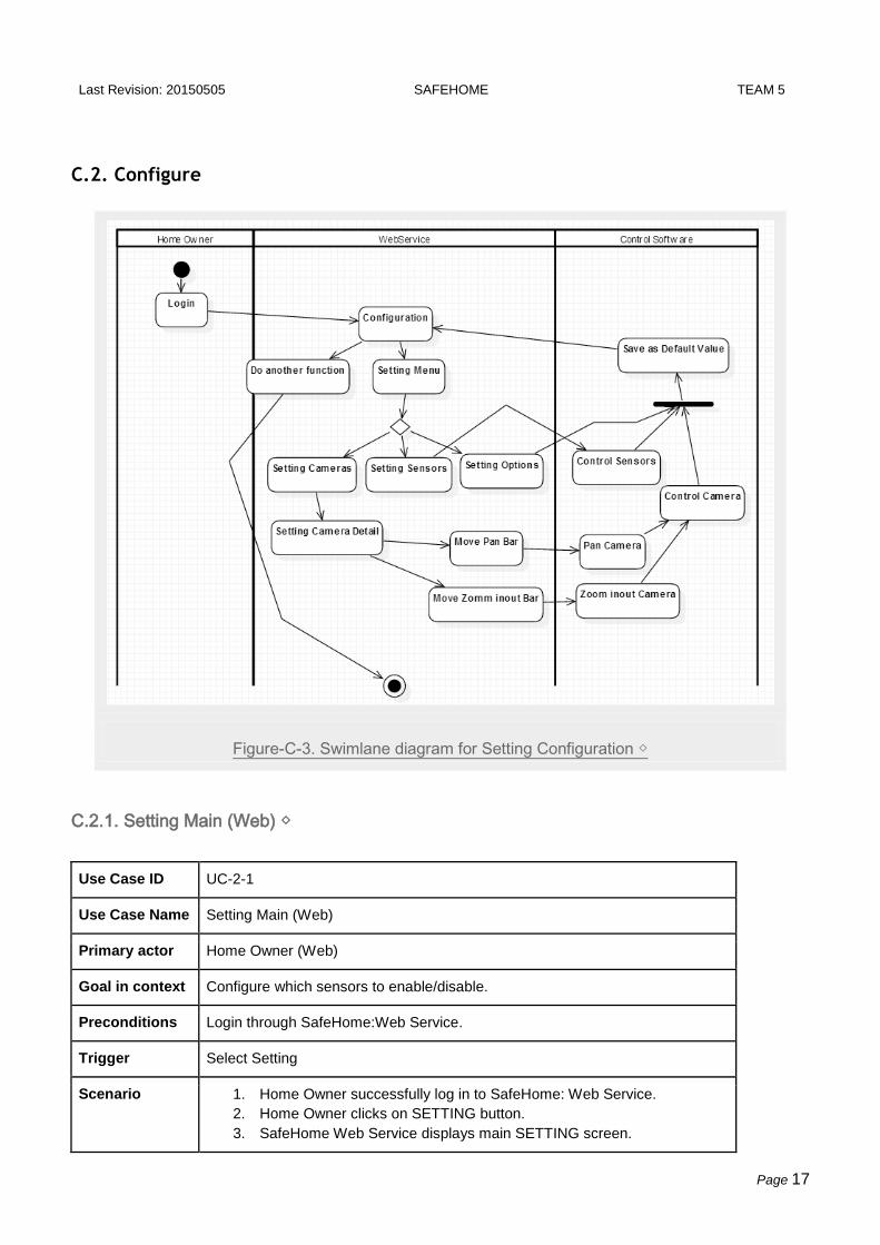
C.2. Configure
Figure-C-3. Swimlane diagram for Setting Configuration ◇
C.2.1. Setting Main (Web) ◇
Use Case ID UC-2-1
Use Case Name Setting Main (Web)
Primary actor Home Owner (Web)
Goal in context Configure which sensors to enable/disable.
Preconditions Login through SafeHome:Web Service.
Trigger Select Setting
Scenario 1. Home Owner successfully log in to SafeHome: Web Service.
2. Home Owner clicks on SETTING button.
3. SafeHome Web Service displays main SETTING screen.

Last Revision: 20150505 SAFEHOME TEAM 5
Page 18
Exceptions 3a. Main screen contains buttons to move another screen including SENSOR
button (UC: Setting Sensors), CAMERA button (UC: Setting Camera), and
DETAIL button (UC: Setting Detail).
Priority High
Frequency Low
Open issues
Channel to
actor
Secondary
actors
C.2.2. Setting Sensors (Web) ◇
Use Case ID UC-2-2
Use Case Name Setting Sensors (Web)
Primary actor Home Owner (Web)
Goal in context Configure which Sensor to enable/disable.
Preconditions Login through SafeHome:Web Service.
Trigger Select Setting - Sensors
Scenario 1. Home Owner successfully log in to SafeHome: Web Service.
2. Home Owner clicks on SETTING button.
3. SafeHome Web Service displays main SETTING screen.
4. Home Owner clicks on SENSORS button.
5. SafeHome Web Service displays Floor Plan with locations of all the
Sensor icons.
6. Home Owner selects specific Sensors icon on the screen to
enable/disable
Exceptions 4a. If Home Owner exits from current display, UC:Setting Main comes out.
Priority High
Frequency Low
Open issues
Channel to actor
Secondary actors

Last Revision: 20150505 SAFEHOME TEAM 5
Page 19
C.2.3. Setting Cameras (Web) ◇
Use Case ID UC-2-3
Use Case Name Setting Cameras (Web)
Primary actor Home Owner (Web)
Goal in context Select specific Camera for detailed setting.
Preconditions Login through SafeHome:Web Service.
Trigger Select Setting - Camera
Scenario 1. Home Owner successfully log in to SafeHome: Web Service.
2. Home Owner clicks on SETTING button.
3. SafeHome Web Service displays main SETTING screen.
4. Home Owner clicks on CAMERA button.
5. SafeHome Web Service displays Floor Plan with locations of all the
Camera icons.
6. Home Owner selects specific Camera icon on the Floor Plan for Detail.
(UC:Setting Cameras Detail)
Exceptions 4a. If Home Owner exits from current display, UC:Setting Main comes out.
Priority High
Frequency Low
Open issues
Channel to actor
Secondary actors
C.2.4. Setting Cameras Detail (Web) ◇
Use Case ID UC-2-4
Use Case Name Setting Cameras Detail (Web)
Primary actor Home Owner (Web)
Goal in context Configure which Camera to enable/disable.
Preconditions UC: Setting Cameras. Home Owner clicked Camera Icon at the Floor Plan in

Last Revision: 20150505 SAFEHOME TEAM 5
Page 20
the Setting-Camera display.
Trigger Select Setting - Camera
Scenario 1. Home Owner selects specific Camera icon on the Floor Plan in display
of Setting Camera.
2. Home Owner clicks the “left” button to move gaze left or clicks the
“right” button to move gaze right.
3. Home Owner clicks the “zoom in” button to zoom in the camera or
“zoom out” button to zoom out the camera.
4. Home Owner clicks the “save” button to save current settting or clicks
“default” to restore previous setting.
Exceptions 2a. If Home Owner exits from current display, UC:Setting Camera comes out.
Priority High
Frequency Low
Open issues
Channel to
actor
Secondary
actors
C.2.5. Setting Options (Web) ◇
Use Case ID UC-2-5
Use Case Name Setting Options (Web)
Primary actor Home Owner (Web)
Goal in context Setting the options.
Preconditions Login
Trigger Select Setting
Scenario 1. Home Owner can change system respond time.
2. Home Owner can decide specific behaviors to do if Home Owner does
not respond to the intruder or fire: i.e. Home Owner can decide whether
using automatic call to police or fire station or not.
3. Home Owner can test whether sensors are running well.
4. Home Owner can set status of Appliances/Lightning/HVAC as well.
5. Home Owner can set to use Autoarm or not.
6. HOme Owner can choose to receive week daily report or not.
Exceptions

Last Revision: 20150505 SAFEHOME TEAM 5
Page 21
Priority High
Frequency Low
Open issues
Channel to actor
Secondary actors
C.2.6. Weekly Mail Report ●
Use Case ID UC-2-6
Use Case Name Weekly Mail Report
Primary actor SafeHome: Web Service
Goal in context System send mail to Home Owner about weekly statistic
Preconditions Every Monday 10:00 a.m.
Trigger Data has been accumulated for weekly report and be ready to be sent to users.
Scenario 1. Data has been accumulated for a weekly report.
2. System automatically produces statistics and send it throught the mail.
Exceptions If system operated in a week, it only accounts for currently accumulated data.
If there’s no comparative data, don’t compare it. (such cases like the system is
recently operated and has no proper previous data)
Priority middle
Frequency weekly
Open issues System automatically compares information about intruders, intrude trials,
suspicious strangers, number of alarms, and time taken of user to check
message, between last week, 4 weeks ago(last month), and 52 weeks ago(last
year) with current week data.
Channel to actor
Secondary actors

Last Revision: 20150505 SAFEHOME TEAM 5
Page 22
C.2.7. Self-Diagnosis ●
Use Case ID UC-2-7
Use Case Name Self-Diagnosis
Primary actor Control Software
Goal in context System diagnosis itself
Preconditions
Trigger Every 12:00 PM
Scenario 1. System start Self-Diagnosis at noon
2. System check Sensors malfunction
3. System check Cameras malfunction
4. System check Alarm malfunction
Exceptions 2,3,4a If System find malfunction notify to Home Owner about malfunction
Priority High
Frequency Daily
Open issues
Channel to actor
Secondary actors

Last Revision: 20150505 SAFEHOME TEAM 5
Page 23
C.3. User Management
C.3.1. Login (Web) ◇
Figure-C-4. Swimlane diagram for Login at Web Service ◇
Use Case ID UC-3-1
Use Case Name Login
Primary actor Home Owner(Web)
Goal in context Login activity
Preconditions Home owner should enter appropriate ID and password.
Trigger Home Owner try to access SafeHome Web Service through the internet
Scenario 1. Home Owner enters the ID
2. Home Owner enters the password
3. SafeHome displays GUI for major functions including sensors, cameras
and current floor plan.

Last Revision: 20150505 SAFEHOME TEAM 5
Page 24
Exceptions 1a. If “auto login” has been checked, SafeHome skip the login process to 3rd
scenario.
2a. If ID or password is incorrect, it shows warning message. If it gets wrong
more than 5 times, SafeHome notify to Home Owner via SMS, and blocks that
IP.
Priority Essential
Frequency Frequent
Open issues
Channel to
actor
Secondary
actors
C.3.2. Logout (Web) ◇
Figure-C-5. Swimlane diagram for Logout at Web Service ◇
Last Revision: 20150505 SAFEHOME TEAM 5
Page 25
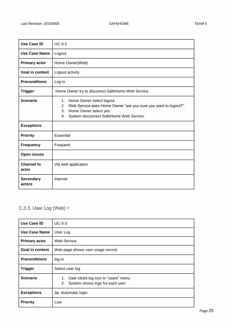
Use Case ID UC-3-2
Use Case Name Logout
Primary actor Home Owner(Web)
Goal in context Logout activity
Preconditions Log-in
Trigger Home Owner try to disconect SafeHome Web Service
Scenario 1. Home Owner select logout.
2. Web Service asks Home Owner “are you sure you want to logout?”.
3. Home Owner select yes.
4. System disconnect SafeHome Web Service.
Exceptions
Priority Essential
Frequency Frequent
Open issues
Channel to
actor
Via web application
Secondary
actors
internet
C.3.3. User Log (Web) ◇
Use Case ID UC-3-3
Use Case Name User Log
Primary actor Web Service
Goal in context Web page shows user usage record.
Preconditions log-in
Trigger Select user log
Scenario 1. User clicks log icon in “users” menu
2. System shows logs for each user
Exceptions 3a. Automatic login
Priority Low
Last Revision: 20150505 SAFEHOME TEAM 5
Page 26
Frequency Not frequent
Open issues
Channel to actor
Secondary actors
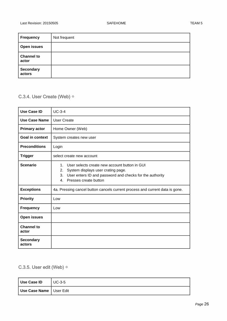
C.3.4. User Create (Web) ◇
Use Case ID UC-3-4
Use Case Name User Create
Primary actor Home Owner (Web)
Goal in context System creates new user
Preconditions Login
Trigger select create new account
Scenario 1. User selects create new account button in GUI
2. System displays user crating page.
3. User enters ID and password and checks for the authority
4. Presses create button
Exceptions 4a. Pressing cancel button cancels current process and current data is gone.
Priority Low
Frequency Low
Open issues
Channel to actor
Secondary actors
C.3.5. User edit (Web) ◇
Use Case ID UC-3-5
Use Case Name User Edit

Last Revision: 20150505 SAFEHOME TEAM 5
Page 27
Primary actor Home Owner (Web)
Goal in context Change the authority of registered user or delete user account.
Preconditions Login
Trigger Select Edit
Scenario 1. The user selects edit menu in the GUI.
2. This system shows edit display about account.
3. The user checks authority or remove registered account.
4. The user can save the changes after edit button again.
Exceptions 4a. Pressing cancel does not save change and exit from edit screen.
Priority Low
Frequency Low
Open issues
Channel to actor
Secondary actors
Last Revision: 20150505 SAFEHOME TEAM 5
Page 28
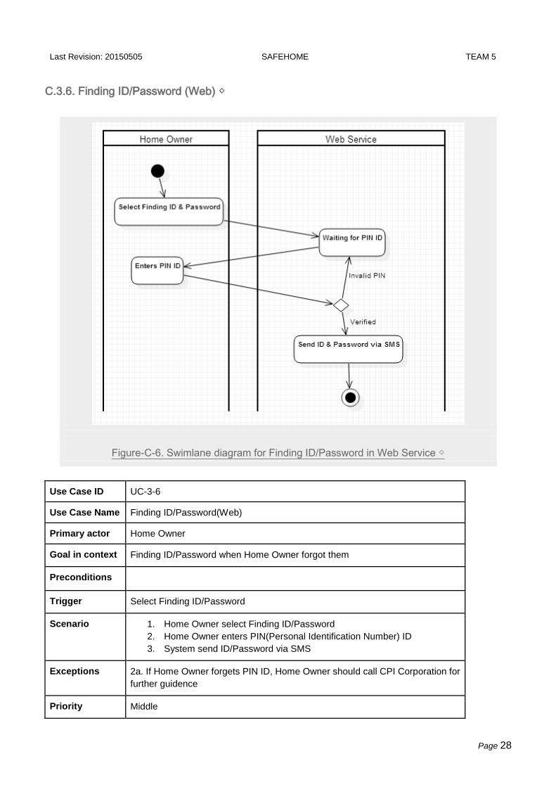
C.3.6. Finding ID/Password (Web) ◇
Figure-C-6. Swimlane diagram for Finding ID/Password in Web Service ◇
Use Case ID UC-3-6
Use Case Name Finding ID/Password(Web)
Primary actor Home Owner
Goal in context Finding ID/Password when Home Owner forgot them
Preconditions
Trigger Select Finding ID/Password
Scenario 1. Home Owner select Finding ID/Password
2. Home Owner enters PIN(Personal Identification Number) ID
3. System send ID/Password via SMS
Exceptions 2a. If Home Owner forgets PIN ID, Home Owner should call CPI Corporation for
further guidence
Priority Middle

Last Revision: 20150505 SAFEHOME TEAM 5
Page 29
Frequency Sometimes
Open issues The research for security problem during the certification of Home Owner is
needed.
Channel to actor
Secondary actors
Last Revision: 20150505 SAFEHOME TEAM 5
Page 30
C.4. Arm/Disarm
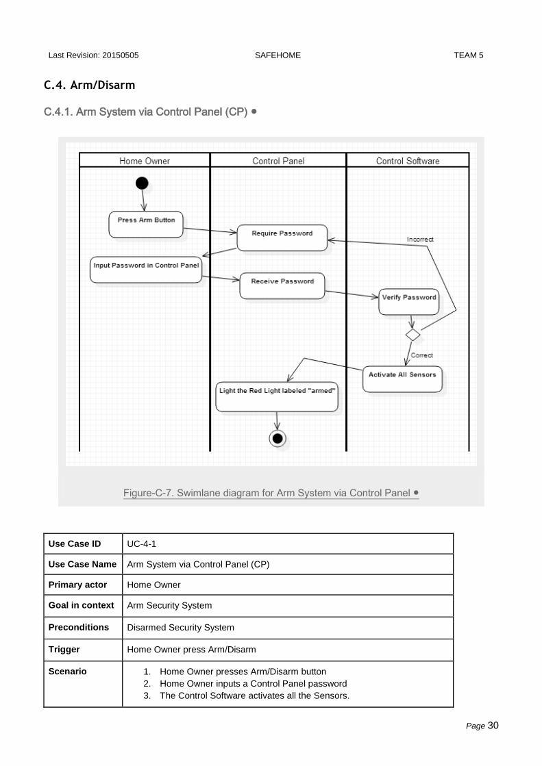
C.4.1. Arm System via Control Panel (CP) ●
Figure-C-7. Swimlane diagram for Arm System via Control Panel ●
Use Case ID UC-4-1
Use Case Name Arm System via Control Panel (CP)
Primary actor Home Owner
Goal in context Arm Security System
Preconditions Disarmed Security System
Trigger Home Owner press Arm/Disarm
Scenario 1. Home Owner presses Arm/Disarm button
2. Home Owner inputs a Control Panel password
3. The Control Software activates all the Sensors.

Last Revision: 20150505 SAFEHOME TEAM 5
Page 31
4. The Control Panel displays that SafeHome is armed with red light
labeled ‘armed’ turned on.
Exceptions 2a. If the password gets wrong, the Home Owner should enter the correct
password again.
Priority High
Frequency Frequent. Every time the Home Owner goes out of home.
Open issues
Channel to actor
Secondary actors
C.4.2. Disarm System via Control Panel (CP) ●
Figure-C-8. Swimlane diagram for Disarm System via Control Panel ●

Last Revision: 20150505 SAFEHOME TEAM 5
Page 32
Use Case ID UC-4-2
Use Case Name Disarm System via Control Panel (CP)
Primary actor Home Owner
Goal in context Disarm security system
Preconditions Armed security system.
Trigger Opens the door legally.
Scenario 1. The Home Owner enters correct password and enters the home
2. The Control Software deactivates specific sensors related to Intruder
Prevention (Motion sensors and Window sensors).
3. The Control Panel displays that SafeHome is disarmed with red light
labeled ‘armed’ turned off.
Exceptions 1a. If the Home Owner gets wrong, Home Owner can re-enter password.
Priority High
Frequency Frequent
Open issues Blocks the system and send SMS to Home Owner if someone gets wrong more
than 5 times.
Channel to actor
Secondary actors

Last Revision: 20150505 SAFEHOME TEAM 5
Page 33
C.4.3. Arm System via Internet (Web) ◇
Figure-C-9. Swimlane diagram for Arm System via Internet ◇
Use Case ID UC-4-3
Use Case Name Arm System via Internet (Web)
Primary actor Home Owner (Web)
Goal in context Arm Security System via Internet
Preconditions Disarmed Security System
Trigger Home Owner clicks on “arm” button on the SafeHome Web Service.
Scenario 1. Home Owner successfully log in to the Web Service.
2. Home Owner clicks on arm button
3. The Web Service displays that SafeHome is armed.
Exceptions 1a. If the password gets wrong, the Home Owner should enter the correct
password again.
1b. Auto login is doesn’t require login proces.
Priority High
Frequency Frequent.

Last Revision: 20150505 SAFEHOME TEAM 5
Page 34
Open issues
Channel to
actor
Secondary
actors
C.4.4. Disarm System via Internet (Web) ◇
Figure-C-10. Swimlane diagram for Disarm System via Internet ◇
Use Case ID UC-4-4
Use Case Name Disarm System via Internet (Web)
Primary actor Home Owner (Web)
Goal in context Disarm Security System via Internet
Preconditions Armed Security System

Last Revision: 20150505 SAFEHOME TEAM 5
Page 35
Trigger Home Owner clicks on “disarm” button on the SafeHome Web Service.
Scenario 1. Home Owner successfully log in to the Web Service.
2. Home Owner clicks on disarm button
3. The Web Service displays that SafeHome is disarmed.
Exceptions 1a. If the password gets wrong, the Home Owner should enter the correct
password again.
1b. Auto login is doesn’t require login proces.
Priority High
Frequency Frequent.
Open issues
Channel to
actor
Secondary
actors
C.4.5. Auto Arm System ◇●
Use Case ID UC-4-5
Use Case Name Auto Arm System
Primary actor Control Software
Goal in context Automatically arm if there is no detection of people inside house.
Preconditions No people or no pets are in the house.
Trigger
Scenario 1. Autoarm is set to turned on from UC:Setting Options.
2. Motion sensor detects no events for 10 mintues.
3. Control Software arms the security system automatically.
Exceptions 2a. Time interval can be set by Home Owner via UC:Setting Options.
Priority High
Frequency High
Open issues If there is pets, how to define automatic arm?
Channel to
actor

Last Revision: 20150505 SAFEHOME TEAM 5
Page 36
Secondary
actors
C.4.6. Overnight Travel Mode (Web) ◇●
Use Case ID UC-2-8
Use Case Name Overnight Travel Mode
Primary actor Home Owner (Web)
Goal in context Arm security mode for overnight travel
Preconditions Home Owner successfully logged in.
Trigger SafeHome receive the command arm Overnight Travel Mode
Scenario 1. Home Owner clicks on “Overnight Travel Mode” button
2. SafeHome arm Overnight Travel Mode and Security System
3. Overnight Travel Mode control appliance, HVAC, lightning according to
the setting
Exceptions
Priority Low
Frequency When Overnight Travel
Open issues
Channel to
actor
Secondary
actors
C.4.7. Extended Travel Mode (Web) ◇●
Use Case ID UC-2-9
Use Case Name Extended Travel Mode
Primary actor Home Owner
Goal in context Arm security mode for extended travel
Preconditions Home Owner successfully logged in.
Trigger SafeHome receive the command arm Extended Travel Mode

Last Revision: 20150505 SAFEHOME TEAM 5
Page 37
Scenario 1. Home Owner clicks on “Extended Travel Mode” button
2. SafeHome arm Extended Travel Mode and Security System
3. Extended Travel Mode control appliance, HVAC, lightning according to
the setting
4. Extended Travel Mode turn on light when night(Light intensity is lower
than baseline) and turn off at 12:00AM
Exceptions
Priority Low
Frequency When Extended Travel
Open issues
Channel to
actor
Secondary
actors

Last Revision: 20150505 SAFEHOME TEAM 5
Page 38
C.5. Intruder Prevention System
Figure-C-11. Usecase diagram for Inturder Prevention System ◇

Last Revision: 20150505 SAFEHOME TEAM 5
Page 39
C.5.1. Intruder detection ◇
Figure-C-12. Swimlane diagram for Intruder Detection ◇
Use Case ID UC-5-1
Use Case Name Intruder Detection
Primary actor Control Software
Goal in context When there is detected intruder, notify to Home Owner.
Preconditions Intruder detecting mode in Safe home system
Trigger Intruder intrude inside home
Scenario 1. Intruder break-in home.
2. Window sensor detects there is breakin.
3. Motion sensor detects Intruder and starts recording(see: UC: Camera
Record) and rings Intruder Alarm.
4. System notify to Home Owner about intruder is appeared via SMS
(System produces SMS including url with information)
5. Home Owner clicks url, then shows web page waiting for log in.
6. If Home Owner successfully logged in, the web page shows the
information about intruder.
Exceptions 3a. If auto-login option is checked already, it is automatically logged in.

Last Revision: 20150505 SAFEHOME TEAM 5
Page 40
5a. If Home Owner does not respond over the setting time, system conducts
promised behavior such as calling police or siren ring.
Priority High
Frequency Not frequent
C.5.2. Intrude Trial Detection ◇
Figure-C-13. Swimlane diagram for Intrude Trial Detection ◇
Use Case ID UC-5-2
Use Case Name Intrude Trial Detection
Primary actor Control Software
Goal in context If intrude trial is detected, SafeHome notify to Home Owner.
Preconditions Safe home system is ready to detect intrude trial.
Trigger Intrude Trial Detected
Scenario 1. Intrude Trial is detected by Window sensors and Door lock.
2. Control Software takes photo who tried to intrude.
3. If the trial detected more than 3 times in 5 minutes, System notify to

Last Revision: 20150505 SAFEHOME TEAM 5
Page 41
Home Owner via SMS about there is intrude trial detected with location
of the sensor and images.
Exceptions 3a. If auto-login option is checked already, it is automatically logged in.
Priority High
Frequency Frequent
Open issues Intrude trial is detected by such actions: when Home Owner entered wrong
password for door lock, or when there has been force to break down the door
lock.
C.5.3. Possilbe Intruder Alarm ◇
Figure-C-14. Swimlane diagram for Possilbe Intruder Alarm ◇
Use Case ID UC-5-3
Use Case Name Possible Intruder Alarm

Last Revision: 20150505 SAFEHOME TEAM 5
Page 42
Primary actor Control Software
Goal in context If Possible Intruder pace up and down in front of door, notify to Home Owner
about this event via SMS.
Preconditions Safe home system detects stranger.
Trigger If there are frequent appearances detected by the camera at the door or for
long time
Scenario 1. Detects Possible Intruder in front of house by Motion sensor.
2. Camera Records the Possible Intruder
3. Control Software notify to Home Owner about Possible Intruder via
SMS
4. Login screen appers when click the url in the SMS that is sent to Home
Owner
5. Shows information after successful login
Exceptions 4a. If auto login is checked, then login automatically.
Priority High
Frequency Frequent
Open issues If motion sensor detects human in front of door and if the detection is frequently
occurred (more than 3 times in 10 minutes) it judges that human as possible
intruder.

Last Revision: 20150505 SAFEHOME TEAM 5
Page 43
C.6. Home Management
Figure-C-15. Usecase diagram for Home Management ●
C.6.1. Fire Alarm ●
Use Case ID UC-6-1
Use Case Name Fire Alarm
Primary actor Control Software
Goal in context Notify to Home Owner that there is fire in the house.
Preconditions
Trigger Sensor detects CO level or detects abnormal high temperature.

Last Revision: 20150505 SAFEHOME TEAM 5
Page 44
Scenario 1. Sensor detects CO or temperature abnormality through sensors.
2. Notify to Home Owner about current event via SMS.
3. Home Owner checks url in the SMS and logs in.
4. SafeHome shows current event thorugh web page.
5. Home Owner choose next action
Exceptions 1a. Home Owner can exclude location to be notified like a gas range in kitchen.
3a. If Home Owner does not check url in time, SafeHome calls 119
automatically.
3b. SafeHome executes fire extinguishing.
Priority High
Frequency Not frequent
Open issues
Channel to actor
Phone call
Secondary actors
Fire station
C.6.2. Gas Alarm ●
Use Case ID UC-6-2
Use Case Name Gas Alarm
Primary actor Control Software
Goal in context If air has abnormal gas, notify to Home Owner.
Preconditions
Trigger Sensor detects CO or high density of hydrocarbon (methane, ethane etc.).
Scenario 1. Sensor detects abnormality.
2. SafeHome notify to Home Owner via SMS.
3. Home Owner check through url sent by SMS and logs in.
4. Home Owner checks situation and decide to enable air conditioning.
Exceptions 3a. Auto login.
4a. If Home Owner does not respond for a certain period, call 119 and if it is not
hydrocarbon, then turns on air conditioning.
Priority High
Frequency Not frequent

Last Revision: 20150505 SAFEHOME TEAM 5
Page 45
Open issues
Channel to actor
Phone call
Secondary actors
Fire station

Last Revision: 20150505 SAFEHOME TEAM 5
Page 46
C.6.3. Water Level Abnormality Alarm ●
Use Case ID UC-6-3
Use Case Name Water Level Abnormality Alarm
Primary actor Control Software
Goal in context Notify to Home Owner about flooding
Preconditions
Trigger Sensor detects flooding
Scenario 1. Water flooding sensor touches water.
2. System notify to Home Owner and call 119
3. Home Owner can check the inforamtion through url after loged in.
Exceptions 3a. Automatic login
Priority Middle
Frequency Not frequent
Open issues
Channel to actor
Phone call
Secondary actors
Fire station
Last Revision: 20150505 SAFEHOME TEAM 5
Page 47
C.6.4. Doggie Angust Alarm ●
Use Case ID UC-6-4
Use Case Name Doggie Angust Alarm
Primary actor Control Software
Goal in context Notify to Home Owner about dog barking
Preconditions Dog barks more than a minute
Trigger Sensor detects dog barks
Scenario 1. Dog barks more than a minute
2. Doggie Angst Alarm detects dog barking
3. System notify to Home Owner
4. Home Owner can check the inforamtion through url after loged in
5. Home Owner can offer food remotely for dog not to bark.
Exceptions 4a. Automatic login
Priority Middle
Frequency Not frequent
Open issues
Channel to actor
Secondary actors

Last Revision: 20150505 SAFEHOME TEAM 5
Page 48
C.6.5. Display Sensor Data ●
Use Case ID UC-6-5
Use Case Name Display Sensor Data
Primary actor Home Owner(Web)
Goal in context Displays CO, Temperature, Water, Gas level and their turn on/off switch and
history.
Preconditions Home Owner successfully logged in.
Trigger Home Owner phone call
Scenario 1. Home Owner clicks on sensor data button.
2. SafeHome displays CO Level, Temperature, Water, Gas level and thire
on/off switch. Also button for history.
3. By clicking turn on/off switch, it turns on/off the sensor.
4. By clicking history button, it displays history of level graph in time
period.
Exceptions 3a. The one should have admin authority to control on/off switch.
Priority High
Frequency High
Open issues
Channel to actor
Secondary actors

Last Revision: 20150505 SAFEHOME TEAM 5
Page 49
C.6.6. Control Appliances/Lightning/HVAC via Internet (Web) ◇
Figure-C-16. Usecase diagram for Control Appliances/Lightning/HVAC via Internet ◇
Use Case ID UC-6-6
Use Case Name Control Appliances/Lightning/HVAC via Internet (Web)
Primary actor Home Owner(Web)
Goal in context Home Owner controls status of appliance/lightning/HVAC via Internet
Preconditions Home Owner successfully logged in
Trigger Home Owner clicked on Home Management button
Scenario 1. Home Owner clicked on Home Management button

Last Revision: 20150505 SAFEHOME TEAM 5
Page 50
2. Home Owner now can control the status of each appliance, lightning,
HVAC.
Exceptions
Priority High
Frequency Frequent
Open issues
Channel to actor
Secondary actors
Last Revision: 20150505 SAFEHOME TEAM 5
Page 51
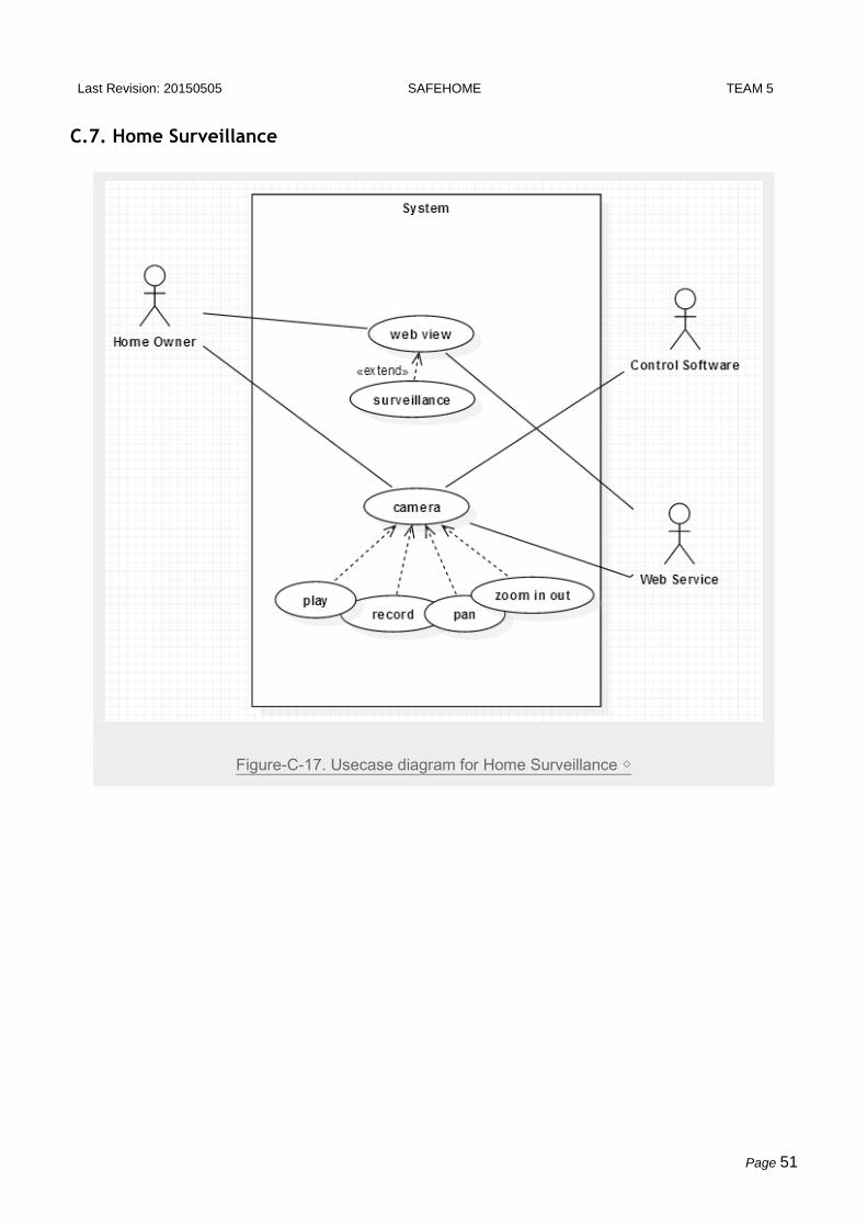
C.7. Home Surveillance
Figure-C-17. Usecase diagram for Home Surveillance ◇

Last Revision: 20150505 SAFEHOME TEAM 5
Page 52
Figure-C-18. Swimlane diagram for Home Surveillance ◇
C.7.1. Temporary Camera Control (Web) ◇
Use Case ID UC-7-1
Use Case Name Temporary Camera Control (Web)
Primary actor Home Owner(Web)
Goal in context Pan camera view and its zoom level through internet via SafeHome Web
Service.
Preconditions Home Owner already logged in successfully.
Trigger Home Owner selected “surveillance” menu, and clicked on “Temporary camera
control” menu.
Scenario 1. Home Owner clicks the “left” button to move gaze left or clicks the
“right” button to move gaze right.
2. Home Owner clicks the “zoom in” button to zoom in the camera or
“zoom out” button to zoom out the camera.

Last Revision: 20150505 SAFEHOME TEAM 5
Page 53
3. Home Owner out from camera setting, camera setting reset to default
4. Home Owner can start record manually
Exceptions 1a, 2a. If Home Owner wants default value, it resets to default via default
button.
Priority High
Frequency High
Open issues
Channel to actor
Secondary actors
For the default setting, see UC-2.4. Setting Cameras Detail (Web). Notice that this UC:Temporay
Camera Control is only for temporary zoom in/out and pan to check real-time status.

Last Revision: 20150505 SAFEHOME TEAM 5
Page 54
C.7.2. Camera Overview (Web) ◇
Use Case ID UC-7-2
Use Case Name Camera Overview (Web)
Primary actor Home Owner(Web)
Goal in context Home Owner can check the overview through thumbnails of each camera
views, and by clicking into it, Home Owner can show the current scenary.
Preconditions Home Owner already logged in successfully.
Trigger Home Owner selected “surveillance” menu.
Scenario 1. Home Owner clicked “surveillance” button
2. The system shows thumbnails of each camera view. The location of
each camera and gaze is displayed in floor plan.
3. The detection logs of camera are gathered and sorted in time order and
displayed in the main.
4. Home Owner clicks each camera for detail.
5. Bigger screen for current camera scenary appears with more details
including logs of change detection.
Exceptions 1a. If Home Owner wants default value, it resets to default via default button.
5a. This follows use-case of “Camera Detail”
Priority High
Frequency High
Open issues
Channel to actor
Secondary actors
Last Revision: 20150505 SAFEHOME TEAM 5
Page 55
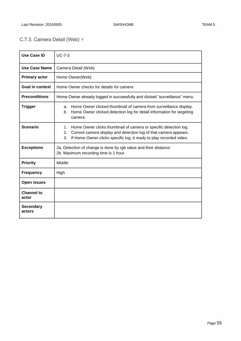
C.7.3. Camera Detail (Web) ◇
Use Case ID UC-7-3
Use Case Name Camera Detail (Web)
Primary actor Home Owner(Web)
Goal in context Home Owner checks for details for camera
Preconditions Home Owner already logged in successfully and clicked “surveillance” menu.
Trigger a. Home Owner clicked thumbnail of camera from surveillance display.
b. Home Owner clicked detection log for detail information for targeting
camera.
Scenario 1. Home Owner clicks thumbnail of camera or specific detection log.
2. Current camera display and detection log of that camera appears.
3. If Home Owner clicks specific log, it ready to play recorded video.
Exceptions 2a. Detection of change is done by rgb value and their distance:
2b. Maximum recording time is 1 hour.
Priority Middle
Frequency High
Open issues
Channel to actor
Secondary actors

Last Revision: 20150505 SAFEHOME TEAM 5
Page 56
C.7.4. Camera Record ◇
Use Case ID UC-7-4
Use Case Name Camera Record
Primary actor Control Software
Goal in context Camera automatically records video by detecting change.
Preconditions Intruder Prevention system detected Intruder or Possible Intruder.
Trigger Current scenary image has difference from stationary scenary (default).
Scenario 1. If Motion sensor detects signal or Window sensor detects signal, the
camera starts recording, suspecting as intruder.
2. Safehome notify to Home Owner about camera starts recording via
SMS
Exceptions 2a. Maximum recording time is 1 hour.
Priority High
Frequency High
Open issues
Channel to actor
Secondary actors

Last Revision: 20150505 SAFEHOME TEAM 5
Page 57
C.7.5. Create Camera thumbnail ◇
Use Case ID UC-7-5
Use Case Name Create Camera Thumbnail
Primary actor Web Service
Goal in context Create camera thumbnail for camera overview.
Preconditions Camera creates still image every 10 min.
Trigger Default scenary created.
Scenario 1. Automatically still image is created every 10 min.
2. Image file is saved, and convert it into smaller size.
3. Next, this smaller image is used as current thumbnail for camera.
Exceptions 2a. Home Owner clicks on another log or camera during the play. When it
occurs, stop the video and change the display.
Priority Middle
Frequency High
Open issues
Channel to actor
Secondary actors
Last Revision: 20150505 SAFEHOME TEAM 5
Page 58
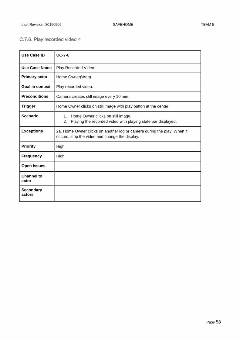
C.7.6. Play recorded video ◇
Use Case ID UC-7-6
Use Case Name Play Recorded Video
Primary actor Home Owner(Web)
Goal in context Play recorded video.
Preconditions Camera creates still image every 10 min.
Trigger Home Owner clicks on still image with play button at the center.
Scenario 1. Home Owner clicks on still image.
2. Playing the recorded video with playing state bar displayed.
Exceptions 2a. Home Owner clicks on another log or camera during the play. When it
occurs, stop the video and change the display.
Priority High
Frequency High
Open issues
Channel to actor
Secondary actors

Last Revision: 20150505 SAFEHOME TEAM 5
Page 59
C.8. Non-Functional Use Cases
C.8.1. Telephone Call Control ●
Figure-C-19. Swimlane diagram for Telephone Call Control ●
Use Case ID UC-8-1
Use Case Name Telephone Call Control
Primary actor Control Software
Goal in context Where there is no internet, Home Owner can control simple function via phone
call through ARS system.
Preconditions Home Owner need to access SafeHome however there is no internet
Trigger Home Owner phone call
Scenario 1. Home Owner calls to the SafeHome ARS number and sharp(#) for ARS
system
2. Enter the ARS password and sharp(#) into the telephone
3. If correct, get into ARS mode.
Exceptions

Last Revision: 20150505 SAFEHOME TEAM 5
Page 60
Priority High
Frequency Low
Open issues Home Owner using ARS can control disarm/arm, and sensor turn on/off.
Channel to actor
Secondary actors

Last Revision: 20150505 SAFEHOME TEAM 5
Page 61
C.8.2. Extra Power Supply ●
Figure-C-20. Swimlane diagram for Extra Power Supply ●
Use Case ID UC-8-2
Use Case Name Extra Power Supply
Primary actor Control Software
Goal in context Extra power supply for SafeHome in blackout.
Preconditions Black out and emergent situation
Trigger Blackout
Scenario 1. Blackout
2. Extra power battery is on, and SafeHome can sustain 30 more minutes
3. SafeHome notify to Home Owner about blackout via SMS.
4. SafeHome gets turns off cameras and sensors except motion and
window sensors to save engergy

Last Revision: 20150505 SAFEHOME TEAM 5
Page 62
Exceptions
Priority Middle
Frequency
Open issues - How much time does extra battery can support in the blackout?
- What if blackout is not accident, but on purpose for intruder?
Channel to actor
Secondary actors

Last Revision: 20150505 SAFEHOME TEAM 5
Page 63
C.8.3. Session Timeout ◇
Figure-C-21. Swimlane diagram for Session Timeout ◇
Use Case ID UC-8-3
Use Case Name Session Timeout
Primary actor Web Service
Goal in context Home Owner automatically logged out if it took 30 minutes after logged in.
Preconditions Home Owner Logged in
Trigger 30 minutes left since Home Owner logged in

Last Revision: 20150505 SAFEHOME TEAM 5
Page 64
Scenario 1. Session Time Out (It took 30 minutes since logged in)
2. Home Owner automatically logged out.
3. Home Owner should re-enter ID and Password to logged in.
Exceptions 2a. If Home Owner is using auto login, he still should do some login activity to
get a new session token. However, this case doesn’t require additional ID and
Password enter.
Priority Middle
Frequency
Open issues If Home Owner is using auto login, session timeout will be effective to solve
security problems?
Channel to actor
Secondary actors

Last Revision: 20150505 SAFEHOME TEAM 5
Page 65
C.8.4. Multiple Access Control ◇●
Figure-C-22. Swimlane diagram for Multiple Access Control ◇●
Use Case ID UC-8-4
Use Case Name Multiple Access Control
Primary actor Web Service
Goal in context SafeHome doesn’t allow multiple concurrent access.
Preconditions Login trial occured while another user is in use.
Trigger Login Trial
Scenario 1. Home Owner try to log in while other User is in use
2. Web Service blocks Home Owner and shows messages “another user
is in use” with user ID in use.
3. Home Owner can identify the user in use and contact that user.

Last Revision: 20150505 SAFEHOME TEAM 5
Page 66
Exceptions 2a. Using Control Panel can ignore previous logged in user and set the
configuration with higher priority. If someone is using Control Panel, no one can
access to Web Service.
Priority High
Frequency Often
Open issues For emergent case, SafeHome should support master administrator account to
logout the previously logged in user and use with higher priority.
Channel to actor
Secondary actors

Last Revision: 20150505 SAFEHOME TEAM 5
Page 67
D. GUI for SafeHome Web Service
GUI-Figure-1. Web Service Login ◇
GUI-Figure-2. Main Menu ◇
Last Revision: 20150505 SAFEHOME TEAM 5
Page 68
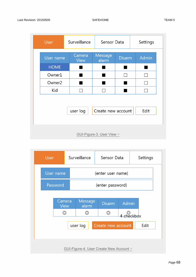
GUI-Figure-3. User View ◇
GUI-Figure-4. User Create New Account ◇

Last Revision: 20150505 SAFEHOME TEAM 5
Page 69
GUI-Figure-5. User Log ◇
GUI-Figure-6. User Edit Account and their authority ◇

Last Revision: 20150505 SAFEHOME TEAM 5
Page 70
GUI-Figure-7. Camera thumbnails with flood plan and detection log. ◇

Last Revision: 20150505 SAFEHOME TEAM 5
Page 71
GUI-Figure-8. When click into camera detail ◇
GUI-Figure-9. Sensor Data Display ◇

Last Revision: 20150505 SAFEHOME TEAM 5
Page 72
GUI-Figure-10. Data Log for each sensor ●

Last Revision: 20150505 SAFEHOME TEAM 5
Page 73
GUI-Figure-11. Settings ●
GUI-Figure-12. Camera Settings ◇

Last Revision: 20150505 SAFEHOME TEAM 5
Page 74
E. Glossary ●◇
Home security: the action of securely protect house from both intruders and internal accidents such
as fires, flooding, gas efflux.
Home surveillance: the action of surveil through camera from both control panels and web service.
Control Panel: The panel to control SafeHome system inside house. It has touch screen and turn
on/off button.
Web Service: Internet service to access SafeHome system. It is running on JRE therefore the user
should install JRE before access to Web Service.
Security zone: Securely protected area in the floor plan which is coverd by sensors and cameras.
Surveillance zone: The zones on the floor plan where camera vision is reached and can be recorded.
Home Owner can set camera zomm in/out or pan to reset the surveillance zone.
Sensor: The device that detects events inside house such as CO level, temperature change, water
flood, and gas efflux.
Arm/disarm: If the security for the home management and home surveillance is on, it is called ‘armed’
state. Otherwise is called ‘disarmed’ state.
House condition: The condition that how many sensors or camera and which location they need in
the house floor plan. It depends on the characteristics of houses.
Main Server: The server that mainly working on the SafeHome. It is fundamentally installed in the
house and provides web access via internet.
Default Image(scenary): The SafeHome automatically takes photo in every 10 min to make camera
thumbnail. SafeHome recognizes this picture as background.

Last Revision: 20150505 SAFEHOME TEAM 5
Page 75
F. Traceability Matrix ●◇

Last Revision: 20150505 SAFEHOME TEAM 5
Page 76

Last Revision: 20150505 SAFEHOME TEAM 5
Page 77