wism ii final report - uwasa
TRANSCRIPT

WISM II Final Report
Tobias Glocker, Caner Cuhac, Reino Virrankoski
University of Vaasa
February 5th, 2013
1 Node Distributor Device: Case
The case is made with a 2 mm and 3 mm thick plastic and the maximum dimensions are9.5 cm x 9.0 cm x 62.5 cm (width x height x length). Figure 1 shows the case of theNode Distributor Device.
Figure 1. Case of the Node Distributor.
2 Node Distributor Device: Electronic Design
The electronic design has been done in the following steps. First it was analyzed whatelectronic components are already on the robot and how these components could beconnected with the electronic of the Node Distributor Device. In the second step thedecision has been made, if the process should be completely controlled by the RobotPC or if the Robot PC should send a start command to a slave device (microcontroller)that takes care of the whole node distribution process. The latter option has been takenbecause it simplified the electronic design. For the slave device the MSP430 Launchpadfrom Texas Instruments (TI) has been selected (see Figure 2).
1

Figure 2. TI MSP430 Launchpad.
In the third step the general overview of the electronic design has been made.
Figure 3. Conveyor with IR Sensors.
Figure 4. General Overview of the Electronic Design.
In Figure 3 the conveyor with two IR Sensors is illustrated and in Figure 4 a generaloverview of the electronic design is shown. The MSP430 Launchpad is connected via
2
Universal Serial Bus (USB) with the Robot PC and it receives its power from the RobotPC over USB. The IR Sensor (S1) is connected with the microcontroller and its task isto detect if a Wireless Sensor Node (WSN) has been dropped on the ground. IR Sensor(S2) stops the conveyor belt motor in the filling process when a WSN reaches the end ofthe conveyor. The power of the motor is taken from the robot’s battery.
In the fourth step the required electronic components were selected.
Required components:
- Infrared Sensors (Receivers TSOP1738 and Transmitters LD271)- Motor for conveyor belt (12V DC Motor from Bebek)- Motor Control Unit (MCU)- Voltage regulator
In the fifth step the required circuits were designed. First the circuits were built on abreadboard before they have been soldered on the Printed Circuit Board (PCB).
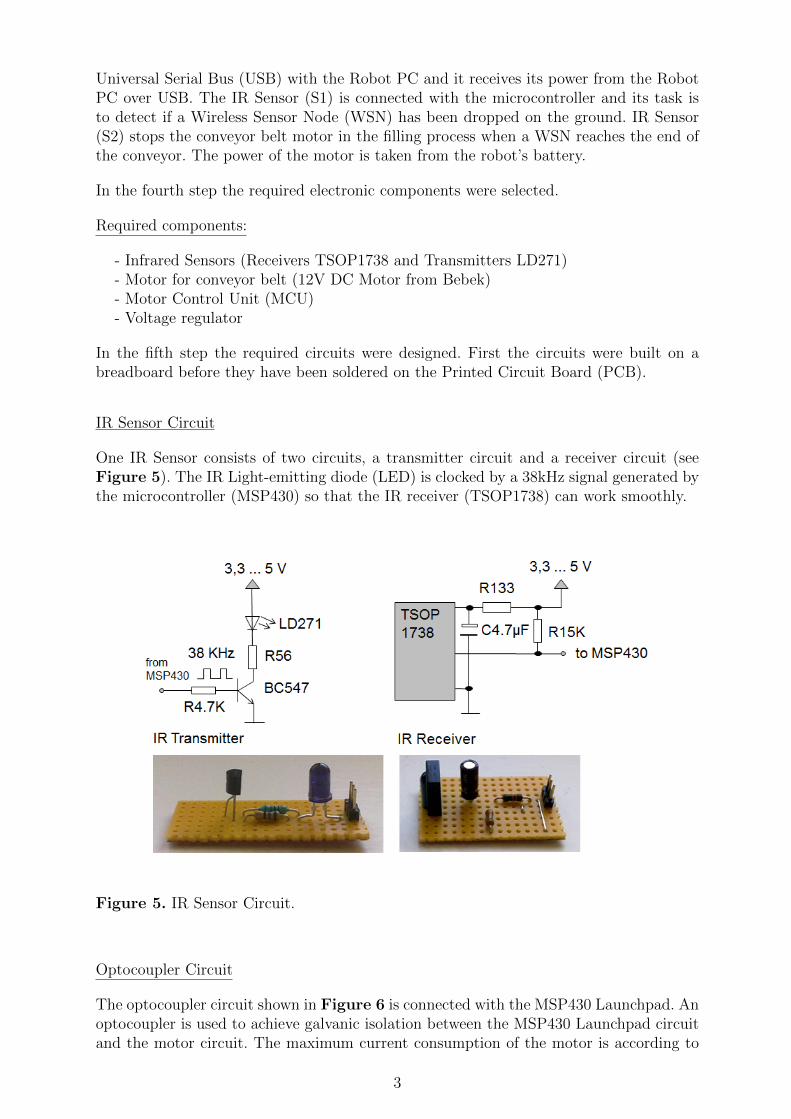
IR Sensor Circuit
One IR Sensor consists of two circuits, a transmitter circuit and a receiver circuit (seeFigure 5). The IR Light-emitting diode (LED) is clocked by a 38kHz signal generated bythe microcontroller (MSP430) so that the IR receiver (TSOP1738) can work smoothly.
Figure 5. IR Sensor Circuit.
Optocoupler Circuit
The optocoupler circuit shown in Figure 6 is connected with the MSP430 Launchpad. Anoptocoupler is used to achieve galvanic isolation between the MSP430 Launchpad circuitand the motor circuit. The maximum current consumption of the motor is according to
3

the data sheet 400mA. Thus a transistor has been selected that can handle a collectorcurrent of 500mA. The motor has a strong torque and a low speed, hence no Pulse-width Modulation (PWM) is required. If a PWM is needed it would be better to replacethe transistor (BC337) with a Metal-Oxide-Semiconductor Field-Effect transistor (MOS-FET) to save power.
Figure 6. Optocoupler Circuit.
Relay Circuit
This circuit contains a relay that controls the motor circuit in the filling process (whenthe device is getting filled with WSNs).
Figure 7. Relay Circuit.
4

Figure 7 illustrates the relay circuit. The motor stops when a WSN reaches the end ofthe conveyor belt (IR Sensor S2 is interrupted).
Electronic for the Motor Control
In Figure 8 the whole electronic for the motor control is presented. There are two ope-ration modes controlled by a switch. One mode is the run mode where the device waitsfor the start command sent from the Robot PC to distribute a WSN. The other mode isthe filling mode where the device is filled with WSNs.
Figure 8. Electronic for the Motor Control.
3 Node Distributor Device: Software Implementation of the Microcontroller
The software for the microcontroller was written in C. The microcontroller is in low powermode until the start character is received. When the start character sent by the RobotPC is received the Interrupt Service Routine (ISR) of the Universal Asychronous ReceiverTransmitter (UART) is called and the motor starts turning until a falling edge interruptfollowed by a rising edge interrupt occurs on the microcontroller pin that is connected tothe IR receiver of IR Sensor (S1). Figure 9 illustrates two cases that had to be consideredbefore the first node is dropped. In the first case the WSN already interrupts the IR Sensorwhile in the second case the WSN does not interrupt the IR Sensor. For that reason itis necessary to wait for a falling edge interrupt and then for a rising edge interrupt. Aproblem that had to be solved was how to stop the motor when the last WSN has beendropped. In order to avoid that the motor is continuously running a watchdog timer isused that stops the conveyor after 10s when no interrupt on the IR Sensor (S1) occurredbefore. Pulse-width Modulation (PWM) is used to generate the 38kHz signal for the IRLEDs. In Figure 10 the general overview of the software implementation is shown.
5

Figure 9. The two cases that need to be considered before the first node is dropped.
Figure 10. General Overview of the Software Implementation (MSP430).
6

4 Node Distribution
The dropping of a node is controlled by a Graphical User Interface (GUI). When thepushbutton on the GUI is clicked, or if a certain button of a connected joystick is pressed,then the Node Drop Publisher of the ICE STORM Server will receive a command to dropone WSN. This command will be forwarded to the ICE STORM Server and from there itwill be forwarded to the Node Drop Subscriber running on the Robot PC. The Node DropSubscriber will send the command over the USB connection to the microcontroller fromwhere the node distribution process starts. Every time a node is dropped the timestampwill be saved, so that the odometer position can be determined. Figure 11 gives anoverview of how the current system works.
Figure 11. Overview of the current Node Distribution System.
5 Suggestion for the Node Distribution in the Future
The WSNs could be distributed in the following way. At the starting point the robot dropsthe first WSN on the floor and continues driving. During the drive the WSN mountedto the robot measures always the signal strength to the previous dropped WSN. Afterdriving a certain distance the robot drops the next WSN on the floor when the signalstrength to the previous dropped WSN is good enough. In order to determine the positionat which the WSN is dropped, the odometer information of the robot could be used if itis accurate enough. This requires that the WSNs in the Node Distributor Device must besorted, so that the WSN with ID1 is distributed first and the WSN with the highest IDis distributed at last.
Previous Received Signal Strength Indicator (RSSI) based distance measurements haveshown (Glocker 2010) that the RSSI values for certain distances vary a lot in differentenvironments. For that reason it is probably better to use the odometer information ofthe robot for determining the position of the WSNs rather as self localization over thenetwork.
7
6 Acknowledgment
We would like to thank Markku Kuusinen and Jyrki Isoniemi for their assistance in themetal workshop and to Kumi-Jarvinen Oy for making the belt of the conveyor. It is tomention that Markku Kuusinen has done the turning and the mounting of the conveyorbelt wheel attached to the motor. We also would like to thank Jani Ahvonen for makingthe plastic wheels with the PCB making machine and the staff members (Jose Vallet,Tapio Leppanen, Jari Saarinen, Marek Matusiak, Matthieu Myrsky, Sami Kielosto) of theAutomation Technology Department at Aalto University in Helsinki for the very goodcollaboration.
7 Bibliography
Glocker, Tobias (2010). Software and Hardware Design of a Miniaturized Mobile Autono-mous Robot Operating in a Wireless Sensor Network. University of Vaasa.
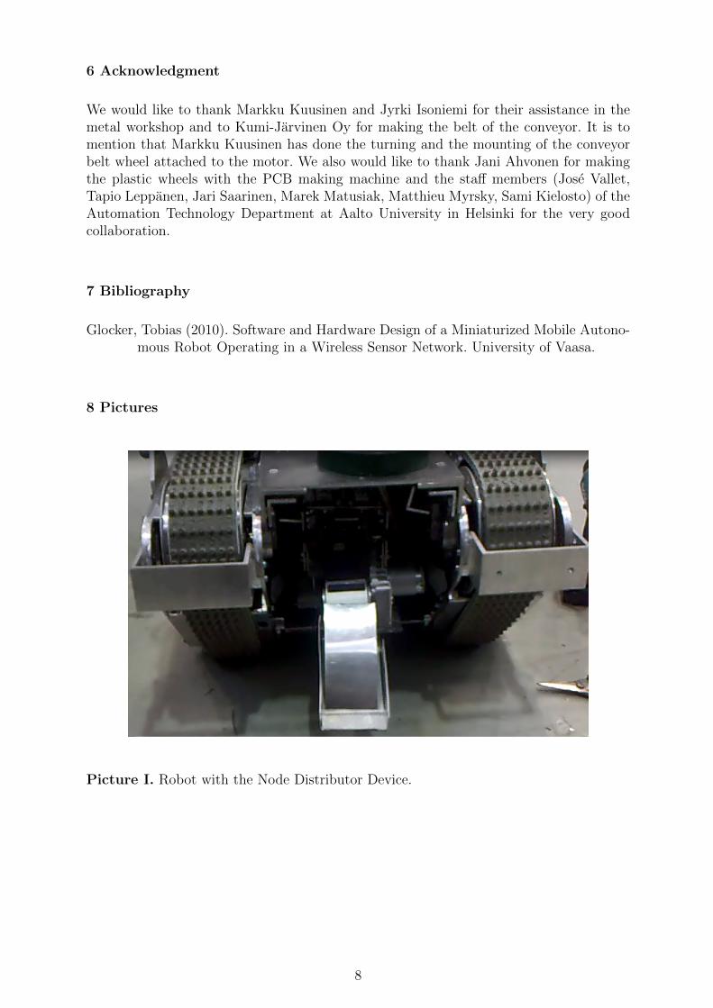
8 Pictures
Picture I. Robot with the Node Distributor Device.
8

Picture II. Robot with the Electronic Board for the Node Distributor Device.
Picture III. Node Distributor Device with the Electronic Board.
9