wiscape view user guide - hubbellcdn view. enter your user and password in the required fields....
TRANSCRIPT

wiSCAPE ViewTM User Guide
Wireless Street Lighting Controls

2
TABLE OF CONTENTS
Connection to a database 3
First steps into wiSCAPE View™ 4
Creating a gateway site 5
Differentiate a LAN network configuration and an Internet configuration 7
Adding and editing devices 8
Creating groups and scenarios 9
Editing groups 10
Editing scenarios 10
Setting up schedules 11
Monitoring your sites 13
Gateway History 14
Orphans 15
Services 15
MIO controller configuration 16
WIR-RM Fixture Module Configuration 19
Generic Timers 20
Level 21
Misc 23
Inputs 25
Metering 28
Alarms 29

3
CONNECTING TO A DATABASE
The sign in window is first thing you will encounter when launching
wiSCAPE™ View.
Enter your User and Password in the required fields.
Next, choose your Database Host. You can use the drop down
menu to select a Host previously used or enter a new one if it is not
in the list. This can either be an IP address (xxx.xxx.xxx.xxx) or a domain name (abc.com).
In general the application will remember the Database Host that you logged into successfully
previously. Under Windows 8 it is mandatory to run the program as an Administrator for this to work,
otherwise you will need to re-enter the Database Host each time you use the program.
To use a database locally, you will have to type or select “localhost.” This will allow you to connect to
a database locally on your computer. This requires that the complete suite and services be installed
on that computer including MySQL, instead of remotely (port of a remotely accessible computer).
It is useful to test and configure devices from a local database on your computer before installing it
to its permanent location.
After choosing the right Database Host, click on the green [Check Mark] button to continue.
Possible Error message:
Can’t connect to MySQL database
This means that either:
• You have entered an incorrect Database Host address
• You are not connected to a network that allows reaching that Database Host (remote computer not
connected)
• The remote database server or service is not running
• The remote 3306 port is not accessible for the network you are currently connected to

4
FIRST STEPS INTO wiSCAPE VIEW™ This is the home screen of wiSCAPE™ View. It shows you the sites that are currently configured. The top menu bar contains
a File menu and Tools menu, a Language selector, quick Mode check box, a connection indicator and two buttons:
[Home] button. If you navigate and get lost into different areas of the database, by pressing the [Home]
button it will bring you back to the first window.
[Change Database] button (Opens the connection window). It is used to switch from a Database to another.
The second menu bar contains:
[Return] button. Returns you to an upper level
[Edit Site], [Edit location] and [Edit device] button. Those buttons allows you to add, remove or modify a site, a location or
a device depending on which level you are in.
[Scheduler Manager] button (used has an advance setting,
more details below).
[Database Backup/Restore] button. Used to create a back-up copy of a Database. It is also used to restore
previously backed-up database. NOTE: By exiting wiSCAPE View you will not lose your modifications made to
the database, therefore you won’t have a “save before exiting” message. However by restoring another Database
without creating backup of your current database, all data from your current database will be overwritten (lost).
[Logger] button. Used to monitor communications between devices and from the system.
[Clear] button. Clears the drop down menu.

5
CREATING A GATEWAY SITE
Click on the [Edit Site] button,
you will then get this screen,
which is where you can create
and edit sites.
To create a Master site, enter a name, and click on the tool icon to configure the site. A Master Site is used as a
central point to access multiple Gateways (see network explanation at page 7).
In the Service Settings Tab:
1. Select Run As Gateway Server Only from the
Service Modem Type drop down menu
2. Type in the server URL or IP address in the
Service URL box
3. Type in the Service Com. Port.
This communication port is an open gate for an
external access. The Default setting is 8001.
Refer to page 7 for network explanation.
4. Save by clicking on the [Check Mark] button.
To create a gateway, enter a name, select RPU site if it is used as a Remote Processing Unit, select Use Carto if
you want to use cartography. Enter the Master site URL address (from the previous step) and its port. Click on the
tool icon to configure the gateway.

6
In the Service Settings Tab:
1. Select the Service Modem Type from the drop down menu. (most of our equipment uses radio frequency modems so select RF Modem unless otherwise specified).
2. Type in the Service URL (must have an Internet access to be accessible remotely). If it’s used locally, type or select “localhost.”
3. Type the Service Com. Port and the Virtual COM Port port that the modem uses.
4. Save by clicking on the [Check Mark] button.
Under the Gateway Settings tab is where to report
to the server the presence of the gateway. It is used to
alert the user of the loss of a gateway. To do so,
1. Adjust the Heartbeat Time as desired (recommend 5 minutes). Heartbeat means that your gateway is going to report itself to the server every X number of minutes.
2. Activate the Udp by clicking on Udp Transfer Enabled
3. Enter the server’s address is the Udp Endpoint
URL field.
4. Click on the [Check Mark] button to save.
Under the Location Settings tab is where you
set the sunrise/sunset time in the scheduler.
Select the City from the scrolling list or enter the
Longitude and Latitude coordinates and Time
Zone manually.

7
When configuring the local network, be aware that your gateways and the master site are going to need
a different port for the WiSCAPE™ remote service on each gateway/master site or it won’t be possible to
connect to the selected gateway.
When configuring your gateways and master site to be used with an Internet connection located at different
sites, it won’t be necessary to use different port for WiSCAPE™ remote service for each gateway/master
site since each site will have a different IP address.
Be careful not to use ports that are already in use, master site may use port 3010 for WiSCAPE™ tool,
Scheduler service on port 2001 and port 3306 is the database port. 8001 is the default remote service port.

8
ADDING AND EDITING DEVICES
To Create or Edit a device, go to the home page by clicking on the
[Home] button located at the top right of the main screen.
Right click on the desired gateway icon and click on Devices.
Start by entering a Name and the Serial Number. Next, choose
the right Device Type. You can type an optional Description by
clicking the [Edit] button. If you click on the [Scenarios] button next the edit button you will see the
scenarios/group associated to the device.
There are two empty fields where you can poll the device to get the Firmware Version and the Protocol
Version (it needs to be powered on). Next, select the Unit to associate with the Consumption Value
and activate its energy log. Finally, the empty fields at the end are dedicated to the geographical
position of the device when using the cartography mode, such as its latitude and longitude coordinates
and physical address.
DEVICES SETTINGS
Right click on the name of the device and a new menu will appear.
If you have a device plugged in and have entered its serial
number, you can try a simple operation like the [On] and [Off]
buttons and the lamp should respond to the selected command.
This will test the functionality of your new module as well as the
ability of the system to transmit and receive data to and from it.
Make sure all appropriate fixture module configurations are
set before plugging fixture on it.
By clicking on Settings, you can edit the settings of your device
in a new window. Parameters settings for the IO controller and
the fixture modules are explained step by step later in this document at page 16. Make sure to read
the instructions carefully to setup your devices correctly. Bad settings could cause unwanted lighting
operations or lighting fixture damage.

9
CREATING GROUPS AND SCENARIOS
To create a group, go to the home page by clicking
on the home button located at the top right of the
main screen.
Right click on the desired gateway icon. From the
Parameters menu, click on Groups.
A new window containing Groups, Scenarios and
Scheduler tabs will open.
In the Groups tab, enter the group Name, which Site
to use, the Code will be automatically generated. It
is possible to enter a Description for this group.
In the Scenarios tab you can create a scenario by
selecting its Group, its Name and a Description.
The buttons used in this section are:
[Edit] Button Used to edit a group or scenario.
[Clone] Button Used to duplicate an existing scenario.
[Scenarios] Links button. Show Devices linked to a specific scenario.
[Run] button. Used to directly run a scenario.
[Reflash] button. Used to reprogram new settings groups and scenarios into the devices.

10
EDITING GROUPS
1. To edit the groups, click on the [Edit] button next to the desired group.
2. Next, click on the [Lamp] button in the upper left corner to select the type of device you want to edit. Select all of the devices you want to add into your group from the devices in the tree list in the
white box at the bottom of the screen.
3. Click on the green [Check Mark] button to accept the changes and re-flash by pressing the [Reflash] button in the upper right corner of the window. If you skip this step, a message will appear when the window is closed. If the device is not re-flashed, the new information will stay in the database but
will not be set into the device.
4. To remove a device from a group, select it and click on the [Delete] button in the upper left corner of the window.
EDITING SCENARIOS
1. To edit the scenarios, click on the desired scenario [Edit] button in the scenario window.
2. Next, click on the [Lamp] button to select the type of device and select all of the devices you want to add into your scenario from the devices in the tree list.
3. Click on the green [Check Mark] button to accept the changes and re-flash by pressing the [Reflash] button.
4. Select the command you want to execute or select to Use Current State.
5. Select the Time.*
6. Run the scenario by clicking the [Run] button in the upper right corner to test your settings and see if it works properly.
*Tip: You can also set the delay between each transmission. This can be accomplished by changing the Time value/waiting time. It’s in milliseconds and can help resolve some communication problems.

11
To create a new schedule:
1. Enter a schedule Name.
2. Select the site it correlates to.
3. To edit it, click on the [Edit] button
4. To clone it, press the [Clone] button.
To edit a schedule:
1. Select your Schedule type.
2. Select which week days the schedule should run.
3. Select the date you want it to Begin and End
4. Choose a fixed Time or Sunrise/Sunset when the schedule will be executed. You can also set a delay (before or after sunrise/sunset) to execute the schedule.
5. Press the [Update] button to save the changes.
To add actions to your schedule:
1. Select the scenario you want to launch or device type you want to control by clicking in the device button (in this case the lamp icon).
2. Click on the device you want to include in the schedule and select the commands.
3. Click on the arrow button to add them into the schedule. To add scenarios click on the [Add Scenario] button.
4. Select desired scenario and click the arrow to add the scenario in the schedule.
5. To delete an item, press on the [Delete] button.
[Delete] button
[Update Schedule] button
[Add Scenario] button
[Broadcast Command] button
[Test Schedule] button
SETTING UP SCHEDULES
To access your schedules, go to the home page, right click on the desired gateway, go in the
Parameters menu and select Scheduler.
The buttons used in this section are:

12
SCHEDULER TEST
You can run a schedule simulation to test your schedule.
It will not actually run the schedule unless you decide
to do so. It will simulate the schedule in fast-forward, so
it is possible to check for any errors without waiting for
the schedule to run at its scheduled time.
From the Scheduler tab, select the schedule you want to test. Right click on the [Edit] button in the Edit Rules
column. A menu will appear showing Running Schedule Test. Once you click it, a new window will appear with
the scheduler simulator.
This is what the scheduler simulator
looks like. You have a drop box
where you can change the Date
and load the schedule with the
[Add] button next to it.
The Executed progress bar shows
the percentage of the commands
tested. You can see the remaining
commands to be tested next to
Count.
The square in the middle of the window is where the commands and scenario information is going to be.
The buttons used in this section are:
Reset the date and time to the one specified in the scenario
Send the commands (Test the schedule for real, not simulating when checked)
Run the schedule
Stop running the schedule
Erase the list of executed commands

13
MONITORING YOUR SITES
With wiSCAPE View you can monitor your devices and watch over
important data like devices status or their history.
To check Devices Status:
From the home page, right click on the desired gateway and click
on Status.
A new window will come up. In this window you can get devices
status. You can also set the interval to check if the device changed
status.

14
ADMIN TOOLS
A section of the drop down menu is called Admin Tools. These tools
are useful to monitor your devices and manage wiSCAPE View.
The section is divided in three sections: Site, Services and Reload
Conditional Rules.
SITE
In the Sites window under the Database
Management tab, there are 7 sub-tabs:
Scheduler, Orphans, Holidays, Interpolate,
Database Management, Trace, Diagnose
Status Result.
SCHEDULER
This tab will show you existing schedules that you
can clone and see their settings.
GATEWAY HISTORY
To view a gateway’s history, go to the home page, right click on the
desired gateway, and click on History from the drop down menu.
Selecting History opens up a window where you can see the history
of past commands/scenarios and current schedules. Select the Begin
and End time period and click on the filter button to show you the

15
ORPHANS
The Orphans tab lets you see three different sub-tabs:
Modules, Groups and Scenario.
In the Groups tab, you can see all existing
groups.
In the Scenario tab, you can see existing scenarios
that are created.
In the Modules tab you can see all orphan devices
or devices that are assigned to any site or location
within a site and edit them.
HOLIDAYS
The Holidays tab lets you create and edit holidays.
Create a new holiday by entering a Name, selecting if
it’s a Specific Date, its Month, its Date (if applicable),
its Day of the Week (if applicable) and the Week
number in the year.
SERVICE
When selecting Service from the Admin Tools menu, a
new window will open with two tabs: Service Settings
and Url Management.
In the Service Setting tab you can edit the site’s
wiSCAPE™ Remote service options. In Url
Management, you can edit the database list you
have in wiSCAPE™ App.

16
MIO CONFIGURATION
To set up the MIO (Multi Input/Output) you must click on the
MIO’s gateway in wiSCAPE™ App or right click on Gateway select
devices .
To add, remove or change groups, click on the Groups
tab. If groups have already been created, select the one
you want to edit and click on the [Flash] button to save
the changes. To ask about the MIO group settings, click
on the question mark icon.
It is the same thing with the Scenarios tab. Select or
create a scenario then select a command to execute with
that scenario
Then right click on fixture module’s
name and select the settings you
want to changes.
Here you can edit the:
• Scenarios
• Groups
• Settings
• Repeater
17
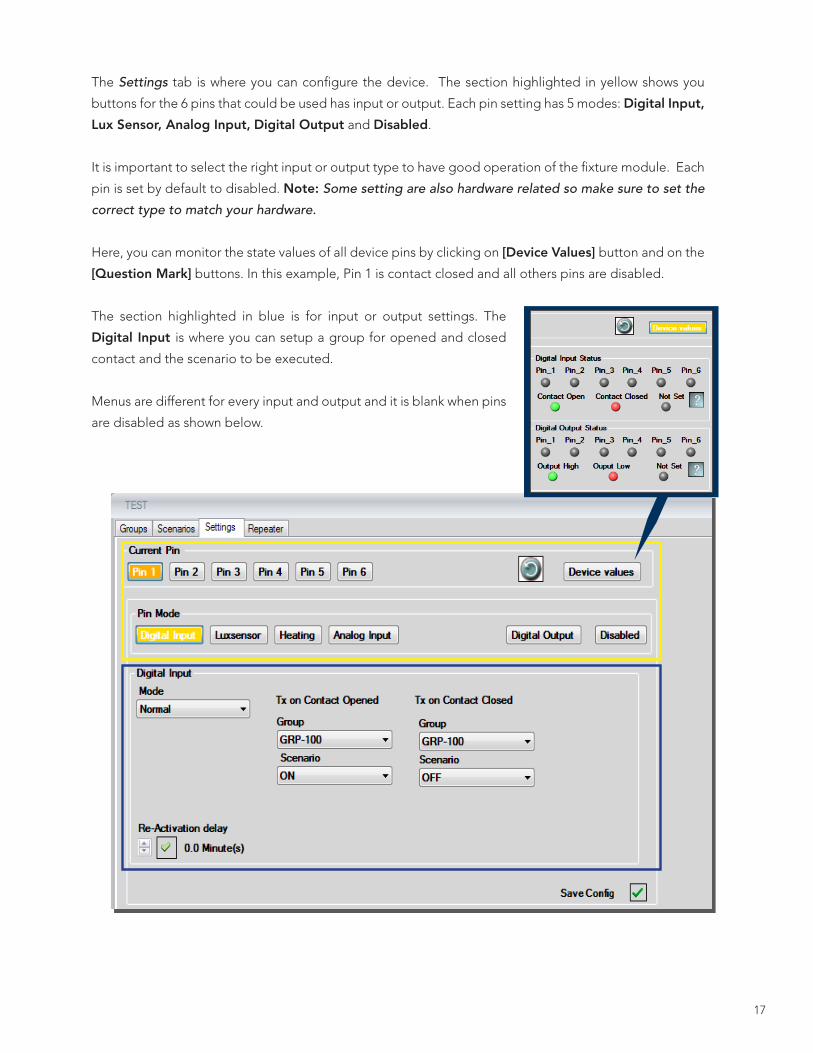
The Settings tab is where you can configure the device. The section highlighted in yellow shows you
buttons for the 6 pins that could be used has input or output. Each pin setting has 5 modes: Digital Input,
Lux Sensor, Analog Input, Digital Output and Disabled.
It is important to select the right input or output type to have good operation of the fixture module. Each
pin is set by default to disabled. Note: Some setting are also hardware related so make sure to set the
correct type to match your hardware.
Here, you can monitor the state values of all device pins by clicking on [Device Values] button and on the
[Question Mark] buttons. In this example, Pin 1 is contact closed and all others pins are disabled.
The section highlighted in blue is for input or output settings. The
Digital Input is where you can setup a group for opened and closed
contact and the scenario to be executed.
Menus are different for every input and output and it is blank when pins
are disabled as shown below.

18
You can also enable or disable the communication under the Outputs tab at the bottom right
portion of the window. Select which communications is to be monitored: System Comm Only or
All Comm and the Period in minutes to wait before declaring that there is a loss of communication.
You can enable one or more pins to proceed to its programmed action during no comms events.
The Repeat tab contains a function that will repeat the action selected on every X seconds with
specified number of retransmissions (repeats) until communication is restored.

19
FIXTURE MODULE CONFIGURATION
Access the device listing by right clicking on the gateway and selecting
Devices from the drop down menu.
Right click on the fixture module name in the device list and the top
right menu will appear. If you have a device energized, you can try the
On and Off functions and the lamp should respond to the selected
command. This will prove the functionality of your module and the
communication of the system. Make sure that the fixture modem is
correctly installed and the connection icon is green.
To access fixture module configurations, click on Settings from the drop
down menu. This will open a new window. Click on the Parameters tab
and you will then be able to edit the settings of your device.
Here you will find the following four functions:
• Generic Timers
• Level
• Misc
• Input
NOTE: Those are the fixture module device settings tabs. There are different settings tabs for each device types. If you have different devices type, older versions or wrong selected device type, options tabs and menus could then appear differently

20
GENERIC TIMERS (GT)
Generic timers are used to create timed commands
or loop commands .
Set the Command A and Command B, the delay
between the two commands to run the Generic
Timer.
Execute generic timers by pressing on the [Run GT]
button according to the GT you want to execute.
There are 10 available GT from GTA to GTJ.
Example2
To create an infinite 30 sec ON and OFF loop you will need two GTs:
1. At GTA select ON for Command A section, type 30 for Sec section and select Generic timer B for Command B section.
2. AT GTB select OFF for Command A section, type 30 for Sec section and select Generic timer A for Command B section
3. Click on the [Save] button.
4. To activate GT, click on [Run GTA] or [Run GTB] and the lamp will alternately turn from ON to OFF every 30 seconds.
NOTE: Generic timers will stop if you select another direct command or if power is turned OFF.
Example 1
To create an ON and OFF generic timer at GTA:
1. In the Command A field, select ON
2. In the Sec field, enter the time you want, for example 30 for 30 seconds or 300 for 5 minutes.
3. In the Command B field, select OFF.
4. Click on the [Save] button. The [Save] button is crucial to save the functions into the fixture module. Make sure that you have a good connection to the fixture module.
5. To activate GT, click on [Run GTA] and the lamp will turn ON for 30 seconds and then turn OFF.
21
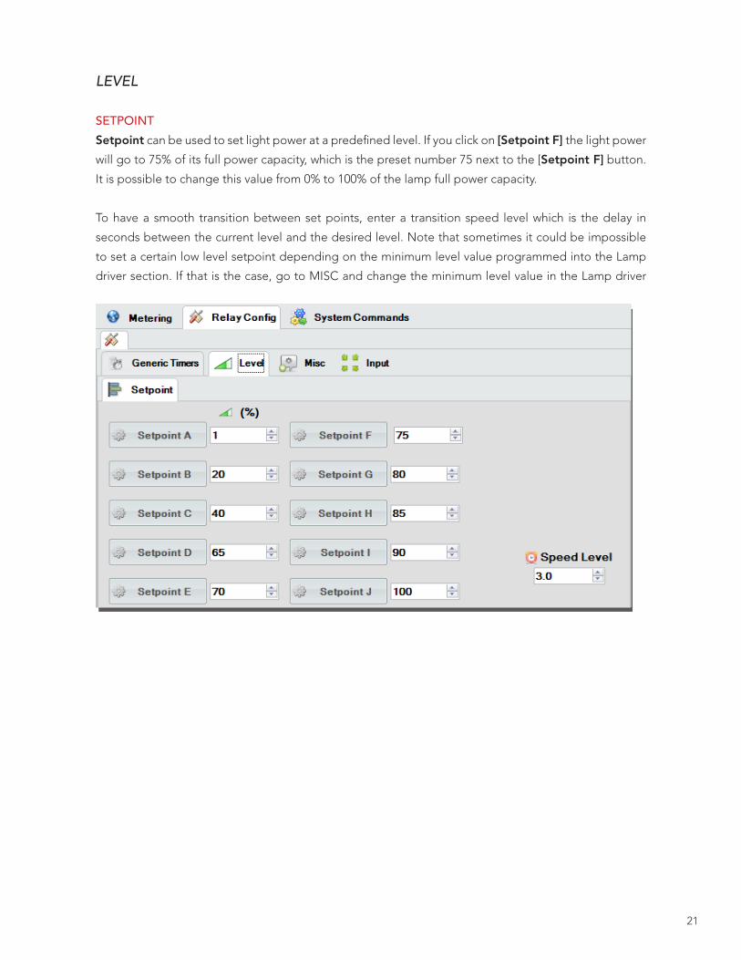
LEVEL
SETPOINT
Setpoint can be used to set light power at a predefined level. If you click on [Setpoint F] the light power
will go to 75% of its full power capacity, which is the preset number 75 next to the [Setpoint F] button.
It is possible to change this value from 0% to 100% of the lamp full power capacity.
To have a smooth transition between set points, enter a transition speed level which is the delay in
seconds between the current level and the desired level. Note that sometimes it could be impossible
to set a certain low level setpoint depending on the minimum level value programmed into the Lamp
driver section. If that is the case, go to MISC and change the minimum level value in the Lamp driver

22
section.
RAMP/DIM
[Ramp Down] can be used to dim lights to the minimal level or [Ramp Up] which make the lights go to
the maximal level. The [Brighten] and [Dim] buttons serve the same purpose but you can stop these
actions with the [Stop] button or the stop command in Generic timers or scenarios those are generally
use to control level from a light switch.
LEVEL SLIDER
The slider can set the intensity of a lamp from 0% on the left to 100% on the right. The slider sends the
level (in %) to the module once the mouse is released.
Offset Comp.(%) sets the offset compensation from -100% to 100%. The offset compensation is a value
that defines the compensation to a level that is receive or measured from an input. For example, if the
module receives a 40% level and the offset compensation is 15%, then the level the lamp will be set to
55%.

23
MISC
The Start Up Level Config fields are used for the
configuration of the fixture module that will execute
at start up when power is applied or restored to the
device.
You can choose Last State, ON, OFF or User Level (set
a user level from 0% to 100%). The default setting is
ON for security purposes to prevent lights staying OFF
after a blackout.
Random Delay is a good option when you have many
devices and you don’t want them to turn ON at the
same time when power is applied or restored.
Allowing an average of 1 second per device can
prevent from creating a peak in demand. (i.e. if you
have 10 devices: random delay =10 sec).
The No-Comm fields can set a command to be
executed by the fixture module if there is no
communication received after specific time. The No
comm function can be disabled by unchecking the
Enable and clicking on the [Save] button.
No comm (Min.) - Time it takes before the No Comm
mode is engaged
Reset Relay (Min.) - Time before the relay resets itself
when there's no communication
Command To Run - Runs the selected command when
the No Comm mode is activated

24
Min Lamp Burn Time to Dim (Min.) - Minimum
time to dim a lamp (in minutes) it is directly linked
to the lamp burn time in the metering section, if the lamp does not have cumulated enough burn time, the lamp won’t dim. This is generally required to maintain the manufacturer’s warranty of dimming fluorescent tubes.
Min Dim Level (%) - Sets the minimum level the lamp is allowed to dim, if the lamp is asked to go to a lower level, it will stay at the minimum level -This setting is to prevent lamp damage, you should always check if your lamp is able to dim, and which level the lamp will be able to go without any damage
Min Percent Level (%) - Sets the minimum level the lamp is allowed, if higher than 0%, this will define a new range and will set the new value as 0%
Max Percent Level (%) - Sets the maximum level the lamp is allowed, if lower than 100%, this will define a new range and will set the new value as 100%
Low Power Mode (%) - Defines the highest level the lamp can go to when in low power mode, it’s the
same as the max percent level but affects the lamp only when it goes on low power mode (reserved for
future use has an energy saving program )
Lamp Type - You have to choose between Ballast Lamp and Triac Lamp.
- If you have ballast driven lamp or LED driver lamp you must choose Ballast Lamp setting and the level control will be done with the 0-10v control wires (gray purple) if available on the ballast. Don’t try to control the level of ballast driven lamp or a led driver lamp with triac lamp setting has a result of severe damages to the driver or ballast.
- If you have a direct input controllable lamp like incandescent lamp you can choose Triac Lamp setting and the level setting will be made directly to the input power of the lamp by changing the phase angle of the fixture module power output. Once again: Don’t try to control level of ballast driven lamp or led driver lamp with triac lamp setting has a result of severe damages to the driver or ballast.
Turn Off Below Min Dim - If checked, the lamp will turn off after reaching the Min Dim value.
The Lamp Driver can set specific options linked
to your lamps. The most important setting to care
is the lamp type. Check the lamp manufacturer
recommendations to set these parameters
correctly and prevent damages to the fixtures.

25
INPUTS
If your fixture module has an Input/Output option with a green block connector, you can connect
and edit many specified inputs like a photocell, a lux meter, a motion sensor and controlling switches.
Refer to the fixture module wiring diagram for specific input and output connections. Make sure to
check the Enable checkmark for each used input and uncheck the other unused ones. Fixture module
connections and setups are explained on the next pages.
If your fixture module is not an I/O type, make sure to uncheck Enable for each unused input and
save. Even if those pins are unavailable physically, they are set into the firmware and can conduct to
unwanted actions if they are enabled. Same thing with I/O type fixture module with unplugged pins.
PHOTOCELL
Enable - Enables the photocell input
Photocell Input Polarity (V) - Select which input polarity to use, either a closed contact which gives
12/24 V during the day or closed contact which gives 0V during the day.
Resend Scenario Delay (Sec.) - Delay (in seconds) to resend the scenario.
Local Command - Select which local command to run when triggered (depending on the Day/Night logic)
Grp - Select which group to run on Day or Night logic.
Scn - Select which scenario to run on Day or Night logic.

26
LUX METER
Enable - Enables luxmeter input
Luxmeter Input Polarity (V) - Select which input polarity to use (Max Lux 10V/Max Lux 0V). Selecting the Max Lux 0V sets the luxmeter in inverted mode, which means that 0V equals 100% while in normal mode
0V equals 0%
Input Voltage (V) - Changes the range of expected sensor reading• Max: Changes the maximum input voltage• Low: modifies the minimum input voltage For example, for a sensor with a 0-5V range, it will take
up to 5V that represents 100%
Output Level (%) - Changes the mapping readings received by the sensor, it is possible using this parameter to offset the value of 1V read to a value executed and transmitted by 20% rather than 10%
DeadBand (%) - Determines the minimum variation of the value read before triggering the execution or transmission. If set too low, it will result in an almost continuous execution and transmission from the slightest change in light intensity measured. If set too high, light power will remain at the same level even if there are great ambient light variations. So it is recommended to use a value between 3 to 15% to reduce the transition rate for lux meter variations.
Reference Input Voltage (V) - Select the reference input voltage. The reference input voltage is the point where the luxmeter will regulate power of a lamp to stay at the same level
Group - Sets which groups to use during transition
Get Value - Read the instantaneous value of the lux meter (In volts, for reference purposes)

27
MOTION
Enable - Enables or disables the motion sensor input.
Motion Input Polarity (V) - Select which input polarity to use with the motion sensor.
Motion Mode• Automatic: The automatic mode executes
and resends while it detects motion (closed contact) and at the expiration of delay 1 and 2, depending on the configuration.
• Manual: The manual mode doesn’t executes or resend at the moment of the motion detection (closed contact), it requires a command to be received (like the press of a switch) before the motion detected is executed. The functions defined by the No Motion Delay 1/2 are executed and transmitted depending on the configuration.
Grace Period Auto On (Sec.) - Set the duration of the grace period, a delay by which the manual mode is selected. If the sensor indicates motion detection behavior is the same as if the module was set to automatic mode, control Motion Detected will be performed and the group/scenario will be transmitted. Once the grace period expires, the control step Motion Detected will be inactive and manual intervention will be required again.
Delay To Resend Level (Sec.) - Sets the delay before retransmitting (in seconds) the group/scenario
Resend Times Qty - Sets how many times the group/scenario is retransmitted
Motion Detected - Select which local action to execute and which groups/scenarios to transmit when motion is detected
No Motion Delay 1 and 2 - Select which local action to execute and which groups/scenarios to transmit when no motion is detected after a specified delay.
BUTTON Enable - Enables or disables button input
Button Input Polarity (V) - Select which input polarity to use with the button(s). When you select 12/24, pressing (closing contact) will expect 12 or 24 volts (between 3 and 30V), if you select 0, a voltage of 0V is expected.
Delay for Button Maintained (Sec.) - Delay before the button press is considered a button held.
Button Press/Button Maintained/Button ReleasedLocal actions to execute and groups/scenarios to transmit when the button is pressed/maintained/released.

28
METERING Current - Displays a reading of the current measured by the module, in amperes
Voltage- Displays a reading of the voltage measured by the module, in volts
Power - Displays a reading of the power measured by the module, in watts
Power Factor - Displays the power factor between 0 to 1. The closer to 1 means a better efficiency.
Energy consumption - Displays how much energy was consumed, in kilowatt-hours
Burn Time (hr.) - Displays the Lamp burn time and the Ballast burn time, which can be useful with some lamps or ballasts that can’t be dimmed before a certain time. You can set the burn time manually if a lamp or ballast driver was replaced by entering it into the corresponding fields and clicking in [Set Lamp Burntime] or [Set Ballast Burntime].
Get metering - Click this button to get the metering values from the module; the readings will replace the
zeros
Change level - With this slider you can manually set a level of lighting for test purpose, the value is transmitted once the mouse is released.

29
ALARMS Alarms can be set to inform user of probable limits overstepping. Alarms can be reached into the Metering menu and clicking on alarm bottom icon.To set up alarms, you have to know the lamp specifications and the power line nominal voltage.
Min Power Factor Threshold (0-1): Power factor is the efficiency factor of the lamp powering system. The closer to 1 the better efficiency. To set up a power factor alarm you have to know what power factor the lamp usually run into and set a lower alarms threshold value.
Nominal Voltage is the voltage that the lamp and module are supposed to be powered with.
Threshold % is the + and – percentage for input voltage limits. The higher the value is, the higher the voltage variations will have to be to send an alarm.
Consumption (W) stands for the fixture module max module consumption, usually not exceeding 3Watts.
For Max Lamp, see the lamp specifications to set it up. Allow 10 to 20 % higher than it’s power consumption for the max lamp alarm setting.
If an alarm has been sent to the system, a message will appear and the lamp mark on the map will shows up like this . If you drag the mouse pointer on that mark, alarm information will be shown with other lamp information.
30
701 Millennium Blvd.Greenville, NC 29607hubbelllighting.com
Alera Lighting
Architectural Area Lighting
Beacon Products
Columbia Lighting
Compass Life Safety
Devine Lighting
Dual-Lite
Hubbell Building Automation
Hubbell Industrial
Hubbell Outdoor
Kim Lighting
Kurt Versen
Prescolite
Progress Lighting
Security Lighting Systems
Spaulding Lighting
Sportsliter Solutions
Sterner
Whiteway
HUBBELL – A NAME YOU CAN TRUSTFounded in 1888 by Harvey Hubbell II, Hubbell Inc. has been a long-time contributor to new product design and manufacturing
innovation. In 1896, Hubbell invented the world’s first lighting control device, the pull chain switch. Over 120 years later,
Hubbell Building Automation, headquartered in Austin, Texas continues this tradition of innovation with the development
of a vast array of innovative energy saving lighting controls.
9601 Dessau Road | Building One | Austin, Texas 78754 | 512-450-1100 | 512-450-1215 fax | www. hubbell-automation.com 4400