wireless transfer of energy alongside information · wireless transfer of energy alongside...
TRANSCRIPT

Ph.D. Thesis Proposal
Wireless Transfer of Energy Alongside Information:From Wireless Sensor Networks to Bio-Enabled Wireless Networks
Hooman JavaheriCollege of Computer and Information Science
Northeastern University
Ph.D. CommitteeAdvisor Guevara Noubir
Bernardo Barbiellini
Marsette Vona
Erik-Oliver Blass
External member David Starobinski Boston University
May 29, 2012

AbstractDespite their constant evolution over the last few decades, wireless communication networksstill struggle with energy conservation. The problem manifests itself in many applications,in particular wireless sensor networks, where communications do not occur frequently andnodes often remain idle, and small-scale communication networks, whose nodes need to to beminuscule. Such applications can achieve optimal energy-efficiency using passive (battery-less)receivers that wirelessly receive energy and information at the same time. In this proposal,we present techniques to simultaneously deliver energy alongside information during wirelesscommunications.
First, we present mechanisms to consolidate energy and information transfer in wirelesssensor networks. We introduce iPoint, a communication system including a passive wirelessreceiver capable of establishing two-way communication with a commodity smartphone. Weprototype and experimentally evaluate our design that includes techniques to ensure efficientdelivery of energy and information and novel communication protocols.
In the second part of the proposal, we study energy and information transfer in bio-enabledwireless networks. These theoretical networks feature wireless communication between wirelessnodes and tiny biological organisms. We introduce possible designs for such networks usingseveral enabling technologies, and present theoretical results on the performance of energy andinformation transfer.

Contents1 Introduction 1
Proposed Research . . . . . . . . . . . . . . . . . . . . . . . . . . . . . . . . . . . . . . . . . . . . . . . . . . . . . . . . 2
2 Related Work 2
3 Consolidated Energy and Information Channels in Wireless Networks 33.1 Energy Transfer Mechanisms . . . . . . . . . . . . . . . . . . . . . . . . . . . . . . . . . . . . . . . . . . . . . . . 33.2 Design Considerations . . . . . . . . . . . . . . . . . . . . . . . . . . . . . . . . . . . . . . . . . . . . . . . . . . . 33.3 Energy Transfer and Communication between A Passively-Powered Device and A Commodity Smartphone . 4
3.3.1 Approach . . . . . . . . . . . . . . . . . . . . . . . . . . . . . . . . . . . . . . . . . . . . . . . . . . . . . . 43.3.2 System Architecture . . . . . . . . . . . . . . . . . . . . . . . . . . . . . . . . . . . . . . . . . . . . . . . . 43.3.3 Multimodal Communication Mechanisms . . . . . . . . . . . . . . . . . . . . . . . . . . . . . . . . . . . 63.3.4 Prototype and Performance Evaluation . . . . . . . . . . . . . . . . . . . . . . . . . . . . . . . . . . . . . 8
3.4 Improvement and Future Work . . . . . . . . . . . . . . . . . . . . . . . . . . . . . . . . . . . . . . . . . . . . . . 9
4 Energy and Information Transfer in Bio-enabled Wireless Networks 94.1 Basic Concepts . . . . . . . . . . . . . . . . . . . . . . . . . . . . . . . . . . . . . . . . . . . . . . . . . . . . . . . . 114.2 Approach . . . . . . . . . . . . . . . . . . . . . . . . . . . . . . . . . . . . . . . . . . . . . . . . . . . . . . . . . . . 12
4.2.1 Signal Transduction . . . . . . . . . . . . . . . . . . . . . . . . . . . . . . . . . . . . . . . . . . . . . . . . 134.3 Enabling Technologies . . . . . . . . . . . . . . . . . . . . . . . . . . . . . . . . . . . . . . . . . . . . . . . . . . . 13
4.3.1 Mechanical Nanoresonators Coupled with Electromagnetic Fields . . . . . . . . . . . . . . . . . . . . . 134.3.2 Non-radiative energy transfer mechanisms . . . . . . . . . . . . . . . . . . . . . . . . . . . . . . . . . . . 154.3.3 RF Energy harvesting . . . . . . . . . . . . . . . . . . . . . . . . . . . . . . . . . . . . . . . . . . . . . . . 16
4.4 Future Work Plan . . . . . . . . . . . . . . . . . . . . . . . . . . . . . . . . . . . . . . . . . . . . . . . . . . . . . . 16
5 Schedule 16
II

1 IntroductionOver the last decade, wireless communication networks have achieved major success and emerged as the key technology forenabling the mobile revolution. Providing mobility and accessibility, wireless communication redefines the notion of networkand connectivity, and powers a huge range of applications. The speed, capacity and robustness of wireless communicationkeep improving everyday, but several challenges remain, energy-efficiency being one of the most notable [1, 2]. Conservingenergy in wireless networks is particularly important, because the wireless nodes are critically dependent on their limitedenergy resource, that is, their battery. Receiving and decoding a wireless signal normally requires a significant amount ofcomputations. In addition, transmitting wireless messages is one of the most energy consuming tasks in today’s computing.Performing such energy-hungry tasks with low efficiency reduces the lifetime of the nodes and eventually causes node deathdegrading connectivity and performance of the network. Therefore, several attempts at hardware and software levelshave been made to tackle this problem: More efficient batteries with larger capacities have been invented [3]; the powerconsumption of wireless nodes has been significantly reduced thanks to advances in low-power electronics and new methodsof computation such as reversible computing [4]; finally, many energy-aware communication protocols and algorithms thatfactor in the energy constraints of wireless nodes have emerged [5, 6, 7, 8].
All wireless networks struggle with the energy conservation issue, yet the problem is more evident in certain applicationssuch as Wireless Sensor Networks (WSN). A WSN usually consists of several spatially distributed nodes that monitor orsense a physical or environmental condition, and transmit the collected data via wireless communication. The sensingprocess generally does not require a lot of energy. In fact, wireless transmission accounts for almost all the node’s energyconsumption. In most cases, the data collection occurs sporadically or upon an external request. Therefore, continuousoperation of a node’s radio, which results in fast battery drainage, is not necessary. Current techniques rely on periodicallywaking the receiver up to synchronize and respond to the requests of a master node [9, 10]. These methods help conserveenergy but are far from optimal. Ideally, the radio component of the sensor node should go into a full-sleep (idle) modethat consumes virtually no energy and wakes up only on external requests or events. This can be achieved by integrating acompletely passive component that acts as a wake-up circuit and relay the external request to the idle node. The challenge ofengineering such a system, which includes software, hardware and communication protocols, is one of the goals of thisstudy.
Having a receiver that consumes no energy while being idle is the optimal solution for any of the scenarios mentionedabove. Note that this goal can not be achieved by simply reducing the energy consumption of the radio components; rather,the energy consumption should be eliminated when no communication is taking place. This rules out the use of conventionalwireless devices which are basically an ensemble of active electronic boards that consume energy while operating, regardlessof how energy-efficient they are. Instead, let us consider the following scenario: Assume that the incoming signal, whichcarries a certain amount of information, provides the receiver with the energy required to extract the information. Onthe other end, the receiver simultaneously executes two actions on the signal. First, it converts the energy of the signalinto a usable form. Second, it runs the decoding procedure to extract the embedded information. In this case the energyconsumption occurs only when there is an incoming signal, and it is fully provided by the transmitter entity. Therefore, thereceiver does not rely on any other source of energy.
Combining energy and information transfer is a promising approach that leads to engineering passive wireless receivers.There are many communication schemes that provide vast range of throughput, complexity and energy-efficiency. Also, a fewmechanisms such as RF energy harvesting have been proposed to transfer energy wirelessly [11, 12]. However, combiningthese schemes presents several challenges. The range and capacity of today’s energy transfer methods are very limited,which makes pairing them with normal communication methods difficult and often impossible. In order to have a functionalsystem, we need to carefully optimize, modify or completely revamp the energy and information transfer mechanisms. Thisincludes building more efficient systems using specialized hardware, and devising better algorithms software solutions thatexhaust the physical limits of the hardware.
Another key factor that greatly impacts the energy conservation problem in wireless networks is the physical dimensions(size) of the wireless device. In context of conventional wireless communications, bigger dimensions normally translate tohigher battery capacity hence longer lifetime. Also, larger systems can accommodate a larger antenna, which increases theantenna gain and subsequently the quality of both transmission and reception given a fixed energy budget. The problemof energy becomes more severe when the size of the system approaches micro and nano scales. In such extreme scales,devices are inevitably passive because they cannot afford to include a portable source of energy (i.e. battery). Providing asolution for energy problem at these limits is particularly important as it opens up exciting new avenues of possibility forwireless networks. Nanorobotics is one of the areas that could greatly benefit from the solution. Another potential outcomeis the possibility to extend the scope of today’s wireless communication from electronic devices to include interactions withbiological systems. The second part of this research will focus on this aspect of the energy problem.
In the case of extremely small systems, the problem shows a radically different face. In such a small scale, there is no room
1

for sophisticated electronic components. Furthermore, especially for biological systems, almost all the information is beingexchanged by means of mechanical and biochemical signals, which are of an entirely different nature from electromagneticsignals. An efficient transduction mechanism is necessary to connect these two seemingly different worlds.
Proposed ResearchIn this work, we plan to explore several techniques to transfer energy alongside information via a wireless link. We classifyour research into the two following studies:
• First, we look into techniques to consolidate the energy and information transfer in wireless networks. We reviewand compare the energy transfer technologies, provide design considerations and sketch guidelines to implementsuch functionality. At the end, we present a communication system that allows two-way communication between acommodity smartphone and a passive receiver. The system features a combination of ultralow-power electronics and RFenergy harvesting. We introduce several techniques to increase the efficiency of the information and energy channels,propose novel communication paradigms and protocols optimized for our setup, build prototypes and finally evaluatethe system performance experimentally. Section 3.3 presents detailed description of the system, our preliminary resultsand future work plan.
• The second part of our research, outlined in section 4, focuses on transferring energy and information to a tinybiological organism through a synthetic interface. We study the enabling technologies that allow us to build suchan interface, challenges ahead and the fundamental limits for energy and information transfer. We propose to studytwo different approaches to transduce electromagnetic signals to biochemical signals. We provide theoretical resultssupported by simulation validations.
2 Related WorkIn this section, we review the related work and research that has been trying to solve the same problem.
RFID tags have the potential to deliver information anytime, anywhere [13, 14]. However, RFID tags have significantlimitations making them impractical for delivering a substantial amount of information to commodity smartphones. Firstof all, equipping smartphones with an RFID reader is a significant and challenging modification to the phone hardware.Secondly, among the three types of RFIDs (i.e., passive, active, and semi-active), only the passive ones do not require abattery and therefore satisfy severe longevity constraints. However, passive RFIDs require the readers to transmit at highpower (in the order of watts), with large antennas. Furthermore, such RFIDs are only capable of storing a very limitedamount of information (e.g., 128 bytes) and are not capable of sophisticated interactions.
Recently, a clever alternative solution to RFID tags and traditional barcodes, called bokode, was developed to deliverinformation from a dot of 3 millimeters diameter encapsulating a high density Data Matrix code [15]. The information isrevealed by putting an off-the-shelf camera in an out of focus mode. This solution has the advantage to reduce the sizeof the tag and increase the information density but still keeping the tag passive. However, bokode still lacks a two-waycommunication capability and requires sophisticated digital cameras (10Megapixel with a large lens) with in/out focuscapability. In the future, if smartphones become equipped with controllable focus cameras, the envisioned iPoint systemmight benefit from integrating a bokode-based LCD display to deliver information to a smartphone at a lower energy cost.
Several RF-energy harvesting techniques and prototypes were explored over the last few years. The WISP platform andits variants harvest energy from RFID reader [16], TV radio stations [17], and are capable of powering a ultralow-powermicrocontroller. The WISP was also used as a batteryless sensor node to communicate with a traditional RFID reader [16]. Itrelies on a high energy sources (30dBm) operating at a medium RF frequency (915MHz). The constraint of the iPoint tooperate on the low RF energy from smartphones (few dBm) and higher WiFi frequency (i.e., 2.4GHz) requires more advancedRF-energy harvesting mechanisms that we present in the next sections. Other platforms for wireless power transfer exist butrequire either high transmission power on the 915MHz band [18], or require highly customized transmitters and receiverssuch as in wireless power transfer via strongly coupled magnetic resonances [19].
While fully operational bio-enabled wireless devices are still a research dream, progress in several fields is makingtheir components more plausible. Recent research has shown that it is possible to manipulate and control cell function, invitro and in vivo, with an external magnetic field [20, 21, 22, 23, 24, 25, 26, 27, 28]. This is achieved by binding MagneticNano-Particles (MNP) to the surface of cells, and applying a static magnetic field to either twist (torque) or pull theMNP. An FM/AM controlled cell excitation was also shown to propagate through from cell to cell as inter-cellular Ca2+
waves [29]. Other researchers have shown that it is possible to down-convert an RF signal to a very-low few frequencytorque of a magnetic nano-particle (∼ 3Hz) [30]. The computer and networking community have been investigating various
2

molecular computing and communications paradigms obtaining theoretical results, defining frameworks, and designingnovel mechanisms for bio-enabled communications [31, 32, 33, 34]. The synthetic biology community has been makingsteady progress on designing, programming and standardizing biological systems [35]. For example, a class of stochasticchemical reaction networks was recently shown to be Turing universal and can therefore compute any computable function.Digital memory biological devices were successfully designed from transcriptional networks. Biological bi-stable switcheswere also successfully engineered. Finally, progress has been made in understanding extremophile bio-organisms, whichthrive in extreme environments from −273C to +151C, tolerate over 1,000 times more radiation than other organisms [36],and can be used as a chassis for synthetic biology.
3 Consolidated Energy and Information Channels in Wireless NetworksIn this part of our research, we aim to study techniques to combine energy and information transfer channels in wireless net-works. We consider a wireless sensor network whose nodes (devices) perform computations electronically and communicateusing Radio-Frequency (RF) signals. In order to eliminate the energy conservation problem, the receiver may not rely ona battery or other unpredictable source of energy, such as solar energy or mechanical vibrations. We propose to design asystem in which the receiver obtains the energy required to receive and decode the transmitted signal from the signal itself.Similar to many WSN models, this system includes two types of nodes: passively-powered receivers, and energy-providermaster node.
3.1 Energy Transfer MechanismsMechanisms to transfer energy from a power source to a wireless device fall into two categories:
• Methods based on electrodynamic induction use inductive coupling between the source and the device, and providehigh-efficiency energy transfer over very short distances, usually less than the dimensions of the inductive component.The efficiency declines significantly over greater distances, which makes such methods ineffective when the signalis high-frequency and long-range, a typical case in communications. Recently developed methods apply resonantinductive coupling to achieve much higher efficiency over longer ranges.
• Methods based on electromagnetic radiation, also called RF energy harvesting, include receivers equipped with rectenna,a specialized component made of an antenna connected to a voltage rectifier that converts energy of the electromagneticenergy of the received signal to a usable DC voltage. These methods attain longer ranges, but exhibit a number oflimitations. At the antenna level, a system using omnidirectional antennas shows a quadratic drop in efficiency withrespect to the distance. Moreover, the losses due to imperfect rectification and antenna matching reduce the efficiencyof the system. Matching and rectification losses can be minimized in a well-designed rectenna. Also, the antennaefficiency improves by using directional antennas and applying beam forming techniques.
3.2 Design ConsiderationsRF energy harvesting allows the use of high frequency signals and does not limit how information is embedded in the signal,therefore meshes well with communication schemes. Nevertheless, the following design considerations should be taken toaccount:
• The amount of energy provided by RF energy harvesting is very limited. Thus, the receiver should consume as littleenergy as possible while operating.
• The receiver needs to obtain a minimum amount of energy before it can demodulate the information. Therefore, thesignal should include a preamble designed to provide the energy to start-up the receiver.
• Having received the signal, the receiver continues to process and respond to the request. The receiver should havealready harvested enough energy to complete the tasks, otherwise the signal needs to include a trail that provides therequired energy and may contain no actual information.
• Because of severe energy constraints, the demodulation process should be as simple as possible, while remainingeffective. Sophisticated decoding mechanisms demand a significant amount of computations and energy, hence are notoptimal.
Most of today’s communication protocols do not fulfill the requirements mentioned above, thus need to be accordinglymodified or revamped. In the following section, we present a system that employs a two-way consolidated energy andinformation channel. The system includes two optimized communication protocols to achieve maximum energy efficiency.
3

Figure 1: Conceptual illustration of how iPoint device performs.
3.3 Energy Transfer and Communication between A Passively-Powered Device and A CommoditySmartphoneIn this section, we propose a system provides two-way communication between a receiver with no source of energyand a conventional smartphone. We present a complete design of the system featuring energy harvesting as the energytransfer method. We explore various technologies, introduce new communication paradigms and build a prototype of thepassively-powered device that we call iPoint.
3.3.1 ApproachA smartphone is an ultimate example of a wireless device. It provides a remarkable combination of data acquisition,computing power and communication interfaces, all in a highly portable package. Our design exploits such capabilities ofthe smartphone to mitigate energy conservation issues.
In the process of designing the iPoint, in addition to considerations stated in section 3.2, we focused on the following keycharacteristics:
• Universality: any smartphone, equipped with the commonly available WiFi interface and camera, should be able toserve as the master node without any hardware modifications. Installing a software application should be sufficient toenable all desired functionalities.
• Interactivity: the device should be able to accept, process, and reply to specific requests. In other words, thecommunication between the iPoint and the smartphone is bidirectional.
These defining features lead us to a design that introduces innovative communication paradigms and techniques and theintegration of a set of fairly unrelated technologies. In the following, we briefly review the system hardware and softwarearchitecture, the components, and the communication paradigms and techniques:
• iPoint components: the iPoint consists of a rectenna optimized for the 2.4GHz WiFi band, an ultralow-power microcon-troller with an LCD-driver and an multi-segment LCD panel.
• Smartphone: virtually any smartphone with a WiFi network interface and an integrated camera.
• Energy-provisioning: the smartphone delivers the energy to the ipoint via WiFi transmission. The iPoint benefits from amore efficient RF energy harvesting circuit optimized for limited transmission power of smartphones, about two ordersof magnitude less than conventional RFID readers.
• Multimodal communication: we propose two novel communication mechanisms to circumvent the severe energyasymmetry and constraints. 1) The information from the smartphone to the iPoint is encoded in the WiFi packet width,which results in much simpler and more energy efficient demodulation at the expense of a lower datarate. 2) Theinformation from the iPoint to the smartphone is encoded as a series of patterns shown on the LCD, to be captured bysmartphone’s camera.
3.3.2 System ArchitectureThis section outlines the architecture of the proposed system. We describe the system components in detail, discuss therequired features, important parameters and trade-offs, and compare design choices. We break down hardware of the iPointinto three components: A rectenna that receives the information and energy, an ultralow-power computing core to processthe data, and a display to show the outputs.
4
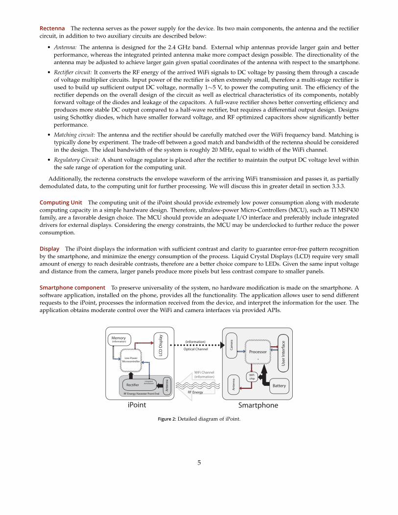
Rectenna The rectenna serves as the power supply for the device. Its two main components, the antenna and the rectifiercircuit, in addition to two auxiliary circuits are described below:
• Antenna: The antenna is designed for the 2.4 GHz band. External whip antennas provide larger gain and betterperformance, whereas the integrated printed antenna make more compact design possible. The directionality of theantenna may be adjusted to achieve larger gain given spatial coordinates of the antenna with respect to the smartphone.
• Rectifier circuit: It converts the RF energy of the arrived WiFi signals to DC voltage by passing them through a cascadeof voltage multiplier circuits. Input power of the rectifier is often extremely small, therefore a multi-stage rectifier isused to build up sufficient output DC voltage, normally 1∼5 V, to power the computing unit. The efficiency of therectifier depends on the overall design of the circuit as well as electrical characteristics of its components, notablyforward voltage of the diodes and leakage of the capacitors. A full-wave rectifier shows better converting efficiency andproduces more stable DC output compared to a half-wave rectifier, but requires a differential output design. Designsusing Schottky diodes, which have smaller forward voltage, and RF optimized capacitors show significantly betterperformance.
• Matching circuit: The antenna and the rectifier should be carefully matched over the WiFi frequency band. Matching istypically done by experiment. The trade-off between a good match and bandwidth of the rectenna should be consideredin the design. The ideal bandwidth of the system is roughly 20 MHz, equal to width of the WiFi channel.
• Regulatory Circuit: A shunt voltage regulator is placed after the rectifier to maintain the output DC voltage level withinthe safe range of operation for the computing unit.
Additionally, the rectenna constructs the envelope waveform of the arriving WiFi transmission and passes it, as partiallydemodulated data, to the computing unit for further processing. We will discuss this in greater detail in section 3.3.3.
Computing Unit The computing unit of the iPoint should provide extremely low power consumption along with moderatecomputing capacity in a simple hardware design. Therefore, ultralow-power Micro-Controllers (MCU), such as TI MSP430family, are a favorable design choice. The MCU should provide an adequate I/O interface and preferably include integrateddrivers for external displays. Considering the energy constraints, the MCU may be underclocked to further reduce the powerconsumption.
Display The iPoint displays the information with sufficient contrast and clarity to guarantee error-free pattern recognitionby the smartphone, and minimize the energy consumption of the process. Liquid Crystal Displays (LCD) require very smallamount of energy to reach desirable contrasts, therefore are a better choice compare to LEDs. Given the same input voltageand distance from the camera, larger panels produce more pixels but less contrast compare to smaller panels.
Smartphone component To preserve universality of the system, no hardware modification is made on the smartphone. Asoftware application, installed on the phone, provides all the functionality. The application allows user to send differentrequests to the iPoint, processes the information received from the device, and interpret the information for the user. Theapplication obtains moderate control over the WiFi and camera interfaces via provided APIs.
Use
r Int
erfa
ce
Battery
Ante
nna
Ante
nna
Cam
era
WiFi chip
Memory (information)
LCD
Disp
lay
Recti!er
ProcessorLow-Power
Microcontroller
SmartphoneiPoint
(information)
RF Energy
Optical Channel
WiFi Channel(information)
integrated demodulator
RF Energy Havester Front End
Figure 2: Detailed diagram of iPoint.
5

Wifi Signalto demodulator
Envelope signalto MCU’s PWM port
MCU SamplingData saved to memory
011111000111111111111111100011111111111100 M0 M3 M2
Bits saved in the memory, to be software decoded by the MCU
M0 M3 M2
Figure 3: PLM decoding.
3.3.3 Multimodal Communication MechanismsBecause of the very low-power transmission of smartphones, the energy harvested by the rectenna is not sufficient to power awireless tranceiver and use conventional communication schemes. In this section, we describe two novel schemes that allowtwo-way communications between the iPoint and the smartphone within such limited energy levels. These schemes leveragesmartphone’s capabilities to reduce the energy budget of the communications. We break down the communications intotwo separate channels: smartphone-to-iPoint (S2I), and iPoint-to-smartphone (I2S). We propose a different communicationscheme for each channel.
Packet Length Modulation To provide energy for the iPoint device, the smartphone transmits WiFi signals. However,demodulating WiFi packets needs an active demodulator requiring energy beyond what iPoint harvester can obtain fromthe signals. We propose Packet Length Modulation (PLM), a scheme in which the information is embedded in the lengthof the WiFi packets. In PLM, each packet length represents a symbol in the code. A message is defined as a sequence ofWiFi packets each representing its corresponding symbol. Note that the smarphone sends the packets via its WiFi interface,which uses the WiFI protocol and does not know about the PLM. The following modifications to existing WiFi protocol arenecessary to implement PLM encoding functionality:
• Since a WiFi access point may not be available, the smartphone creates an ad hoc WiFi network.
• The iPoint lacks any WiFi tranceiver, hence no acknowledgment packet is sent back to the smartphone. Therefore, PLMuses broadcast packets to prevent unnecessary packet retransmission.
• The WiFi packet length depends on the size of the packet, rate of the communication, and fragmentation. To have arobust encoding, the WiFi interface should transmit at a fixed rate without using any rate-adaptation algorithm.
• Assuming the PLM mechanism uses M different packet lengths, each packet encodes log2 M bits of information. Thefragmentation threshold determines the maximum packet length, hence the number of the symbols, and should be setto the maximum.
All modifications above are made in the software; no hardware modification is necessary.To decode the PLM signal, the iPoint retrieves the length of the received WiFi packets. First, the rectenna generates the
envelope signal of the received WiFi packet, and sends it to the computing unit. The computing unit samples the signal,determines its length, and maps it to its corresponding symbol. Predefined start and stop flags can be used to distinguishthe beginning and the end of a message. Figure 3 illustrates the steps of PLM decoding.
PLM Rate Analysis: Let M denote number of the packet lengths in the PLM. Assume the transmitter sends thepackets at rate, R. Let Smin be the smallest packet size. Smin is determined by the MCU clock to guarantee packet detectionand length estimation, and by the energy harvester efficiency and MCU energy requirements. We consider packets of sizemultiples of Smin, Si = i× Smin. Hence, the average size of the packet would be Savg = Smin+Smax
2 = (M+1)2 Smin. Further
assume a message is a sequence of packets separated by idle periods of the length equal to Sidle. We can calculate the timeneeded to send a packet, Tp as following:
Tp =Savg + Sidle
R=
(M + 1)Smin + 2Sidle2R
(1)
Each packet encodes log2 M bits of information. Therefore,
6
P2 P1P3
LCD Patterns(Encoded Information)
Data
The Output MessageDisplay Time
Figure 4: LPC Encoding for a M-segment LCD panel.
RPLM =log2 M
Tp=
2 log2 M× R(M + 1)Smin + 2Sidle
(2)
The values of Smin and Sidle are determined by the maximum sampling rate of the MCU at iPoint side. Assuming fMCUis the sampling frequency of the MCU, we have,
Smin, Sidle >2
fMCU(Nyquist theorem). (3)
Hence,
RPLM(max) <2R log2 M
(M + 1)(2
fMCU) + 2(
2fMCU
)
RPLM(max) <log2 M× R fMCU
M + 3. (4)
Note that during idle periods, iPoint does not receive energy from the smartphone. This lowers the output voltage ofthe rectifier which may result in unwanted shut-down of the system. To maintain the harvested voltage level above thedesired threshold, Smin needs to be larger than Sidle. We define the duty cycle of the system as the Smin/Sidle ratio. Theminimum duty cycle that allows the system to operate continuously depends on the implementation and may be evaluatedexperimentally. Moreover, Smax = M× Smin should be smaller than the fragmentation threshold in the smartphone’s WiFiinterface.
Finally, the smartphone needs to send preamble and trail WiFi packets to provide the energy required for the iPoint tostartup, process the information and send the reply message back through I2S channel.
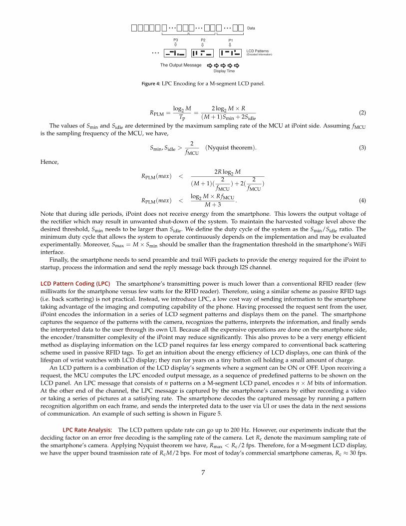
LCD Pattern Coding (LPC) The smartphone’s transmitting power is much lower than a conventional RFID reader (fewmilliwatts for the smartphone versus few watts for the RFID reader). Therefore, using a similar scheme as passive RFID tags(i.e. back scattering) is not practical. Instead, we introduce LPC, a low cost way of sending information to the smartphonetaking advantage of the imaging and computing capability of the phone. Having processed the request sent from the user,iPoint encodes the information in a series of LCD segment patterns and displays them on the panel. The smartphonecaptures the sequence of the patterns with the camera, recognizes the patterns, interprets the information, and finally sendsthe interpreted data to the user through its own UI. Because all the expensive operations are done on the smartphone side,the encoder/transmitter complexity of the iPoint may reduce significantly. This also proves to be a very energy efficientmethod as displaying information on the LCD panel requires far less energy compared to conventional back scatteringscheme used in passive RFID tags. To get an intuition about the energy efficiency of LCD displays, one can think of thelifespan of wrist watches with LCD display; they run for years on a tiny button cell holding a small amount of charge.
An LCD pattern is a combination of the LCD display’s segments where a segment can be ON or OFF. Upon receiving arequest, the MCU computes the LPC encoded output message, as a sequence of predefined patterns to be shown on theLCD panel. An LPC message that consists of n patterns on a M-segment LCD panel, encodes n×M bits of information.At the other end of the channel, the LPC message is captured by the smartphone’s camera by either recording a videoor taking a series of pictures at a satisfying rate. The smartphone decodes the captured message by running a patternrecognition algorithm on each frame, and sends the interpreted data to the user via UI or uses the data in the next sessionsof communication. An example of such setting is shown in Figure 5.
LPC Rate Analysis: The LCD pattern update rate can go up to 200 Hz. However, our experiments indicate that thedeciding factor on an error free decoding is the sampling rate of the camera. Let Rc denote the maximum sampling rate ofthe smartphone’s camera. Applying Nyquist theorem we have, Rmax < Rc/2 fps. Therefore, for a M-segment LCD display,we have the upper bound trasmission rate of Rc M/2 bps. For most of today’s commercial smartphone cameras, Rc ≈ 30 fps.
7

START
START
AlignmentGuides
LCD Display
iPoint
[ ]1 0 0 1 0 0 0 1 0 0 0 00 0 0 1 0 10 0 0 1 0 0
RecognizedPattern
Applying Mask
Figure 5: LPC decoding. To make de-coding faster, the user is asked toalign the image of the panel withina virtual box, then the frame issampled only on the intersectionsof mask grid-lines (Narrow dashedlines).
D
Figure 6: The iPoint prototype boards: A) Computing core upper layer (LCD display is shown). B) Computing core lower layer(MSP430 is shown). C) RF energy-harvester front end, 10-stage Greinacher voltage multiplier. D) The realization of iPoint version 2.1.
3.3.4 Prototype and Performance EvaluationWe prototyped different versions of the iPoint based on the design described in Section 3.3.2. The latest version (Ver. 2.1)is shown in Figure 6. In this section, we explain the implementation of the components in detail. In addition, severalexperiments are carried out in order to accurately characterize the prototyped device and prove the functionality of thedesign components. This section presents the detailed description of the testbed and experimental results.
PrototypeThe smartphone used in the experiments is the HTC Dream also known as T-Mobile G1 running Android mobile deviceplatform Ver. 1.6. This 3G phone is equipped with a 528 MHz Qualcomm ARM11 Processor, 192 MB of DDR SDRAM,320×480 pixel LCD Display with 180 ppi, 3.2 megapixel camera with auto-focus capability, and a WiFi (802.11 b/g) wirelessinterface [37]. We developed a software application in Android platform that sends multiple PLM-modulated requests,and performs the LPC decoding. The WiFi interface was configured to send broadcast packets at a fixed rate of 1 Mbps,the lowest rate supported by WiFi communication. Ideally, the application should create an ad hoc network, but theAndroid’s support for the ad hoc mode is currently limited. As an alternative solution for prototyping, the smartphoneconnects to an auxiliary WiFi network created by an external access point. We use UDP/IP, as opposed to TCP/IP, toavoid unnecessary retransmissions caused by TCP flow-control mechanism. For the iPoint’s rectenna, we implemented a10-stage modified Greinacher circuit, a full-wave rectifier with parallel RF inputs connected to a 2.4 GHz whip antenna.We used high-performance low-leakage RF capacitors, and schottky diodes (HSMS-282 series from Avago technologies)with forward voltage threshold of 150∼200 mV, the lowest available. The value of intermediate capacitors were chosenexperimentally to maximize the output DC voltage. The rectenna then was matched on WiFi channel 1 (2.412 GHz) using anLC matching network. The first stage of the rectifier circuit was used as an envelope-detector circuit for PLM decoding. Forthe communication core, we embed a TI MSP430F417, an ultralow-power microcontroller from Texas Instruments. This 16-bitflash MCU provides desired computing capabilities at low power consumption. It features 32 kB + 256 B of flash memory,1 kB of RAM, Low supply voltage of 1.8 V, integrated LCD driver for 96 segments, on-chip comparator that can be usedfor finalizing the PLM signal demodulation, and very low active power consumption of 200 µA at 1 MHz, which makes
8

it a reasonable choice for the iPoint prototype. The LCD panel selected for this generation of prototyped device was a 26segment watch LCD display.
Experimentation ResultsTo characterize the efficiency of the rectifier circuit, a MXG Vector Signal Generator was used to feed the rectifier via a 0.5feet coaxial cable, and the output voltage level of the rectenna was measured. The rectifier was fed with a WiFi signal in awide range of input power, from -20 dBm to 15 dBm. The output voltage and efficiency were measured without a load andwith a load of 140 kΩ, which is close to the MCU impedance in active mode. Rectifier shows efficiencies up to 72%. Theresults are shown in Figures 7a and 7b.
In order to test the functionality of the integrated demodulator of the front end, packets with different sizes were sent overthe WiFi channel by the smartphone while the output of the energy harvester and integrated demodulator being measured.The rate of communication was fixed to 1 Mbps. The result is shown in Figure 7c.
To reduce the power consumption of the computing core, we aggressively underclock the MCU. The iPoint’s computingcore tasks, such as PLM decoding and LPC encoding, do not demand a very fast clock, hence the clock frequency may bereduced to a few kilohertzs. Figure 7d illustrates the results of our measurements of the MCU’s power consumption runningthe same instructions at different clock frequencies.
Minimum duty cycle as one of the important characteristics of the iPoint system was discussed in section 3.3.2. Wemeasured the output DC voltage of the rectenna for different duty cycles. The results are summarized in figure 7e.
The power consumption of two LCD panels with different sizes were measured: Panel 1 (3 cm2, 24 segment), and Panel2 (1.8 cm2, 26 Segments). A test image was taken from the LCD panels at the same distance and under the same lightenvironment while the same pattern were displayed on both panels. The contrast of the panels were compared digitally inAdobe Photoshop. To create a given desired contrast, we measured the required voltage and input current for each panel.The Larger panel, requires 2.9 V drawing 49 µA (142.1 µW), whereas Panel 2 requires 1.9 V drawing 21 µA (39.9 µW).
3.4 Improvement and Future WorkThe preliminary results of the project were published in [38]. Our plan to further optimize the design of the iPoint is asfollows:
• Size: The latest version of the prototype, Version 2.1, consists of two separate PCBs. We attempt to decrease the physicalsize of the device by unifying the old boards in the future versions of the prototype.
• Antenna and matching: In order to further miniaturized the device, we plan to replace the whip antenna in the olddesign with a compact integrated (PCB) antenna. The new design features a new matching circuit that is significantlyeasier to tune.
• Simulations: we plan to perform an extensive set of simulations using Agilents ADS simulation package in order tochoose the optimal values for electronic components of the design. Simulation validation will also help to predict theperformance of the new designs before printing new PCBs and results in reducing the project cost.
4 Energy and Information Transfer in Bio-enabled Wireless NetworksWhile energy efficiency remains one of the main challenges in wireless networks [1, 2], biological systems are well known tobe extremely energy efficient. From the brain, which performs outstandingly complex tasks with only a few tens of Watts, tothe ear, which can carry out the equivalent of a billion floating-point operations per second, biological systems are manyorders of magnitude more efficient than our state of the art wireless systems. Such an efficiency gap can be explained by thefact that today’s electronic systems rely on transistors (∼30nm) to perform very basic functions, while biological systems relyon nano-level machines (e.g., proteins) to perform specialized and complex functions. A natural, although clearly challengingquestion is if we can build biologically-enabled wireless networks. Note that the theme of this research is bio-enabledmechanisms which are fundamentally different from bio-inspired techniques in which the functionality of the electronicdevice is inspired by an existing natural mechanism. This quantum leap in efficiency is analogous to the improvements fromPascal’s mechanical calculators to electronic calculators. We argue that recent advances in bio-engineering technology andsynthetic-biology will dramatically expand the frontier of wireless communication research.
An example of systems that can benefit from such research is a wireless sensor network. Most wireless sensor nodesrely on a periodic wakeup to be paged for requests. This results in significant energy consumption and increased delay. ABio-enabled Sensor Network (BSN) composed of a nano-power sensing device that can go into a full sleep mode but can stillbe woken up using a fairly long-range RF signal could solve this problem. The idea is to transduce a weak Electro-Magnetic
9

−25 −20 −15 −10 −5 0 5 10 1510
0
101
102
103
104
105
Input Power (dBm)
Rec
tifie
rs’s
Out
put V
olta
ge (m
V)
140 K No Load
(a) Performance of the energy harvesterunit.
!20 !15 !10 !5 0 5 10 15 2020
30
40
50
60
70
80
Input power (dBm)
Recti
fier E
fficine
cy (%
)
(b) Energy-harvester efficiency as a func-tion of input power.
0.
1.
3.
4.
0.
1.
3.
4.
(c) The outputs of Energy harvester (Vcc and integrated demodulator (envelope signal). Note that thesize of the packet is easily detectable. The WiFi communication rate was fixed to 1 Mbps. harvester’soutput level is fairly smaller than the peaks of envelope signal. That reason is the long idle timesbetween packet transmissions. The data is captured by a Infinium MSO8104 oscilloscope from AgilentTechnologies. The plot is regenerated in MATLAB.
1.6 1.8 2 2.2 2.4 2.6 2.8 3 3.20
50
100
150
200
250
Voltage (V)
Input
curre
nt (μ
A)
8 KHz16 KHz64 KHz128 KHz
Clock Frequency
(d) Power consumption of MCU for differ-ent clock frequencies.
0 200 400 600 800 1000 12000
0.5
1
1.5
2
2.5
Size of the packets (bytes)
Max
imum
recti
fied
powe
r (m
W) f
or 1
50 KO
hm lo
ad
6 ms20 ms100 ms
Sidle
(e) The rectified output voltage as a func-tion of the packet length for different idletimes Sidle (therefore duty cycles).
Figure 7: Performance evaluation results.
10

(EM) signal into biological signals and use a biological device to demodulate the information embedded in the original EMsignal [34].
A second application is the engineering of bio-agents that can synthesize and self-assemble a protein/polymer-based radioreceiver (such as the recently demonstrated nano-radio [39]), that diffuses through the body and targets specific cells such ascancerous cells, liver cells, or even neurons (by generating anti-bodies that binds to targeted membrane proteins [20, 40]) toallow the remote monitoring, manipulation (e.g., opening/closing ion channels as demonstrated in the remote control of C.Elegans worms [24]), and even destruction (e.g, by triggering apoptosis processes) of the targeted cells.
An exciting challenge at the frontier of three research communities, namely communication networks, bio-physics, andsynthetic biology, is how we can design a wireless communication system that:
• Interfaces with bio-organisms for medical applications such as remote control, and monitoring of cells.
• Leverages bio-computation and communication for efficiency.
Building bio-enabled wireless communication systems requires overcoming several challenges.
• Signal propagation: is challenging because bio-materials severely limit the propagation of wireless signals (e.g., electricalfields are highly attenuated) [41].
• Interfacing: controlling bio-physical processes is difficult as these processes are still not well understood, and sensingand extracting bio-signals to the external world is not easy using non-invasive self-assembling devices.
• Size: devices should be small enough to interface with bio-mechansims at the molecular level.
• Robustness and stability: bio-organisms are very sensitive to the environment and need to be engineered for extremeenvironments[36].
• Health: the proposed technology should be safe to people and the environment.
4.1 Basic ConceptsConnecting two seemingly different worlds requires detailed understanding of their similarities and differences. Whilebiological organisms seem to completely differ from electronic circuits used to built wireless networks, a closer look at thesecomplex systems reveals a few fundamental similarities. This section presents an overview of the biological world fromsystems perspective and breaks down some of its important characteristics:
Information flow and biological sensitivity In systems biology, an organism can be viewed as a complex network of itscells. A cell is a well-defined biological entity able to receive (sense), process, and generate information. In this biologicalnetwork, information travels using bio-signals. Bio-signals exist in the form of mechanical, chemical, or in some cases electricalsignals. Examples include pressure, signaling molecules such as hormones, ion concentration change, and electrical pulsesproduced in neurons. From systems perspective, there are three types of bio-signals.
• External stimuli: the information perceived by the cell from the extracellular micro-environment. These signals activatea specific receptor (i.e. a protein located on the cell membrane) on the cell and trigger a reaction.
• Intracellular signals: intermediate signals produced inside the cell in the process of creating the response. These stepsnormally include numerous chemical reactions and protein-protein interactions.
• Cell responses: the output generated by the cell, which alters the state of the cell or the extracellular environment.
The process by which a cell generates a response to an external stimuli is called signal transduction, and the sequence ofsteps required to complete the process is referred to as signaling pathway [42]. The correct execution of the transduction relieson availability of necessary proteins in the cell. Cells produce such proteins using information encoded in their genetic code.The biological behavior of the cell in an environment depends on the variety of its signaling pathways. In multi-cellularorganisms, the complex network of signaling pathways coordinates the function of the organism as a whole. Understandingthe information flow in signaling pathways allows the use of a bio-organism as a tool for computation and communication.In addition, advanced synthetic biology and genetic engineering techniques have made it possible to design and engineer newsignaling pathways with enhanced functionality [35]. The sensitivity of a cell to external stimuli is determined by the varietyof its receptors, special proteins that normally reside on the cell membrane. Receptors are classified by the stimuli to whichthey are sensitive, as well as the signaling pathway they trigger. External stimuli include temperature change, mechanicalstress and strain, signaling molecules, or a change in electrochemical voltage in the environment.
Speed Signal transduction execution time depends on the complexity of the pathway and varies for different cell responses.A change in sodium ion concentration in neurons completes in a few milliseconds while a complicated process such as geneexpression might take days to finish [42].
11

Ante
nna
Connection to bio-e
Low-PowerMicrocontroller
Cell
Wireless Device
Bio-sensor
Wireless to BioLink
Bio-sensorB
Extracellular Environment
EM
External Stimuli
Cell responses
Interface
Figure 8: The components of a simple interface between a cell and a wireless device.
Energy Natural selection has forced bio-organisms to maximize their energy efficiency. Biological organisms show superiorenergy efficiency compared to today’s ultra-low power electronics. As an illustrative example, human brain consumes 20–30watts of power, less than a third of most advanced CPU designs [43]. Also, ears and eyes outperform the state-of-the-artsensors at the same level of energy consumption.
Complexity Even in the simplest form (i.e. single-cell), bio-organisms manage to perform a variety of complicated tasks.The ability to produce a vast number of proteins with different functionalities permits bio-organisms to extend the complexityof their actions while preserving their size and efficiency.
4.2 ApproachIn a biological system, each cell can be modelled as a Multiple Input Multiple Output (MIMO) device where inputs andoutputs denote external stimuli and cell responses, respectively. On the wireless side, a wireless node exchanges theinformation with its surroundings using high-frequency electromagnetic (EM) signals. Depending on the communicationscheme, information is encoded in amplitude (energy level) or the frequency of the signal. An interface should providean efficient channel to exchange information and energy. It should not perturb the functionality of either side, which isparticularly important for the biological entities because of their high sensitivity to environmental changes. Ideally, theinterface does not concern how information is processed at its endpoints such as details of decoding schemes in the wirelessnode or the internal signaling pathway in cells. In our model, the endpoints of the interface are assumed to process theinformation and generate signals without error.
Figure 8 illustrates a simple two-way interface between a wireless node and a cell. The information flow consists of thefollowing two links:
• Cell to node: Cell responses normally alter the state of the surrounding micro-environment. Therefore, a wireless nodeequipped with a properly designed bio-sensor can observe the effect of a cell response in the extracellular environmentin a non-invasive fashion. Bio-sensing techniques used to extract the information from bio-signals are beyond thescope of this work, but an extensive body of multidisciplinary research can be found in the literature for interestedreaders [44, 45].
• Node to cell: To trigger any cell response, the corresponding combination of stimuli should be present. Either propagationof EM signals directly produces a stimulation in the extracellular space, triggering a transduction process, or the cellperceives a secondary effect of the EM signal delivered by auxiliary nano-devices. The possibilities and challenges tocreate the link from wireless device to biological system are the main focus of this part of our research and discussed indetail in the following sections.
The main goal of interfacing mechanism is to convert the message sent by the wireless node in the form of an EM signalto a meaningful set of bio-signals. At the molecular level, EM signals can be seen as series of changes of EM fields in theenvironment.
Systematic noise Biological systems, similar to any communication system, experience systematic noise [46]. Sinceinteractions and signaling in biological systems happen at the molecular level, the energy level of the contributing particles(molecule) nears kBT; hence, the system contains a substantial amount of thermal noise. To ensure a successful activation
12

of the receptor, the energy level of the transduced bio-signals must exceed the threshold level of one or two order ofmagnitude greater than the system’s thermal noise. The high volume of the noise in the system makes efficient signalingquite challenging.
4.2.1 Signal TransductionOne approach to signal conversion is to use the immediate effect of the wireless signal (i.e. meaningful changes in electricand magnetic fields) as the biological stimulus. Some cell receptors are known to be sensitive to electrochemical voltagevariations. For example, ion channels are trans-membrane proteins that control the concentration of a specific ion across thecell membrane by regulating the ion flux. Meaningful changes in an ion concentration such as calcium (Ca++) have beenshown to trigger several signaling pathways, and serve as the key mechanism involved in the inter-cellular signaling [33].For example, the voltage-gated ion channel, which is activated by electrochemical voltage variation, is potentially suitable forinteraction with EM signals. The direct use of EM signals as biological stimulation meets the following pair of challenges:
• Electrical attenuation: The extracellular fluid is electrically conductive due to the concentration of ions and polarmolecules. Therefore, the electric field becomes largely attenuated while propagating in the biological environment [41].In other words, electrical properties of the biological environment channel the energy of the signal to particles otherthan the target molecule. This forms a two-fold obstacle: reducing the energy of the transduced signal below thedetection threshold, as well as creating the possibility of unintended activations elsewhere.
• Magnetic blindness: Research has shown that biological systems exhibit limited interactions with magnetic fields due tothe absence of magnetic materials [46]. Although natural magnetoreception has been spotted in rare organisms such asmagnetotactic bacteria and the migratory birds [47], most biological systems lack the natural ability to perceive themagnetic field. However, it is possible to synthetically add a magnetic receptor to the cell. See section 4.3.1 for moredetails.
A limited number of cell receptors are able to perceive EM fields. In fact, most of the signaling pathways are regulated bychemical, thermal or mechanical stimulation. A more practical approach is to construct a non-EM biological stimulus fromthe secondary effects of EM signals in biological media. A few possibilities are listed below:
• Thermal: It has been shown that high frequency EM fields generate heat while propagating in biological media. Givensufficient amount of time, it may create a temperature increase competent to activate a targeted thermoreceptor [48].
• Mechanical: Electric and magnetic fields produce mechanical effects (i.e. Force, Torque, etc.) on charged and magneticmaterials. Such effects generate a series of motion, vibration, stress, or strain in the cell structure that can be detectedby a mechano-sensitive receptor that resides on the cell membrane [49].
• Chemical: A combination of thermal and mechanical interactions can be used to release an originally trapped signalingmolecule in the extracellular environment, consequently causing the activation of corresponding receptor [24].
4.3 Enabling TechnologiesEfficient and effective implementation of the mechanism mentioned above often requires auxiliary machinery. Thesenano-scale machines (structures), or simply bio-devices, provide the required functionality and compatibility to facilitate thesignal conversion in the biological environment. Due to the small size, they can safely attach to biological surfaces or float inthe extracellular environment. In this section, we discuss potential enabling technologies that can be integrated, or possiblycombined in the design of an efficient and robust interfacing mechanism. The current state of the technology, challenges, andthe improvement possibilities are summarized.
4.3.1 Mechanical Nanoresonators Coupled with Electromagnetic FieldsMechanical nanoresonators exhibit resonance behaviour involving the mechanical vibrations of the system elements. Thenatural frequencies of such resonances will, generally, be in the radio frequency range. Nano-scale mechanical resonatorscoupled with electromagnetic fields have been receiving significant attention recently [39, 50, 51]. The ability to interact withelectromagnetic fields allow such resonators to be essential parts of nano-scale systems. Imaging, sensing, and targetedactuation in nano scale are among several emerging technologies that rely on efficient energy and information transfer.
In principle, nanoresonators may couple to electromagnetic fields by the charge distributions (Electric coupling) or bythe magnetic moment they carry (Magnetic coupling). Traditionally, electric coupling has received more attention since theelectric field intensity is much larger than magnetic field intensity in electromagnetic waves. On the other hand, magneticcoupling of mechanical resonators with electromagnetic waves becomes more practical as the size of the system decreases. In
13

m
F
E
q
kL
B
Figure 9: An overview of nanoresonators with electric (right) and magnetic (left) coupling. The viscoelastic properties of the resonatorsare identical.
fact, magnetic coupling holds important advantages over electric coupling. First, magnetically coupled systems can providemore selective and localized energy transfer. That is due to the fact that magnetic fields, unlike electric fields, couple weaklywith non-targeted surrounding media, which are often not magnetic. Therefore, magnetic signals penetrate deep in variouskinds of media, suffer from considerably less attenuations, and interact with targeted resonator inaccessible to electric signalswith the same level of energy. In addition, magnetic dipoles are normally more stable than electric dipoles, and do notrequire significant energy from outside to maintain their state.
We propose to investigate the interactions of radio-frequency electromagnetic fields with mechanical nanoresonators,particularly quantitative assessment of the energy transfer in such nanoresonators. First, we present a universal model formechanical nanoresonators that includes electric and magnetic coupling, and describe the dynamics of the system.
Theoretical Model Here, the mechanical structure of the nanoresonator consists of an elastic cantilever beam equipped witha specialized tip, which is responsible for electromagnetic interaction, vibrating in a low-viscosity fluid such as low-pressureair. The viscoelastic model of the nanoresonator includes the coefficient of mechanical elasticity, k, and the dissipationcoefficient, D. For a cylindrical beam with a spherical tip, k ∼ EIc/L3, where E, Ic and L are Young’s modulus, secondmoment of cross-section and the length of the beam, respectively. Moreover, as shown in Ref. [52], the combination ofintrinsic (e.g., plastic deformation, surface effects) and extrinsic (e.g., viscous forces of the surrounding fluid) dissipationmechanisms determines the value of D. Because the size of the nanoresonator is much smaller than the wavelength ofthe external field, the energy transfer is in the form of interactions between the incoming field and dipole moment of thenanoresonator’s tip. In this work, we look at two nanoresonators that have identical mechanical structures, yet interactwith electromagnetic fields via different coupling mechanisms: Electric coupling (E) and Magnetic coupling (M). In electriccoupling, an AC electric field, E = E cos(ωt), produces a force, F, on an electric charge distribution, q, placed at the tipof the nanoresonator and causes oscillatory deflections in the cantilever. A very similar model has been discussed in theNanotube Radio [39]. For magnetic coupling, assume the tip of the resonator is made of a ferromagnetic material such asmagnetite (Fe3O4) and has a magnetic moment of µ. An AC magnetic field, B = B cos(ωt), generates a magnetic torque,Tm = µ× B, and rotates the tip leading to oscillatory beam deflections. A device based on this model has been built andused for ultra-sensitive magnetic resonance force microscopy (MRFM) [50, 53]. Figure 9 illustrates the mechanical structure of thenanoresonator and the aforementioned coupling mechanisms. We begin by looking at the dynamics of each model, then lookclosely at the resonant energy transfer performance of the nanoresonators.
The dynamics of the system can be expressed by Langevin motion equation for the tip of the resonator. After linearizationfor small deflections, we have
mf x + Dx + kx = F cos(ωt) + N(ωt), (5)
where x is the displacement at the tip of the beam, mf is the effective mass of the system, and D is the dissipation coefficient.F = qE for electric coupling, while F = T /L = µB/L for magnetic coupling. The term N(ωt) is an stochastic force withthe correlation of 〈N(t)N(t + ∆t)〉 = 2DkBTδ(∆t), where kB and T are the Boltzmann constant and temperature in Kelvin,respectively. In our systems of interest, as will be shown later, the amount of energy stored in the resonator is well above kBT.Therefore, we safely omit the stochastic term from (5). The system’s natural frequency and the quality factor are given by
ω0 =
√km
(6)
Q =
√kmD
. (7)
The steady state solution of the system isx(ωt) = xm cos(ωt + ϕ), (8)
14

where xm and ϕ are the maximum deflection of the tip and the phase shift given by
xm(ω) =F/m√
(ω2 −ω20)
2 − (ωω0/Q)2(9)
ϕ(ω) = arctan
(ωω0/Qω2 −ω2
0
). (10)
Finally, the necessary condition to achieve resonance is D <√
2km.The dynamics of the system can also be expressed by the following Langevin equation for rotational oscillation.
Iθ + Cθ + κθ = T cos(ωt) + ψ(ωt) (11)
Here θ = x/L is the angular displacement, I ∼ mL2 is the system’s second moment of inertia, κ ∼ kL2 is the rotationalspring constant of the cantilever, and ψ is the stochastic torque caused by the thermal noise. For magnetic coupling, T = µB,while T = qEL in the case of electric coupling. The natural frequency, quality factor, the steady state solution, and resonancecondition will be identical to the previous approach. A detailed analysis can be found in our previous work [56].
4.3.2 Non-radiative energy transfer mechanismsElectromagnetic radiation dilemma During Electro-Magnetic Radiation (EMR), energy is transmitted as electro-magneticwaves. For a plane wave of a fixed frequency, the power density of the wave is given by its poynting vector,
S =1
µ0E× B (12)
Also, the time-averaged magnitude of the poynting vector is
〈S〉 = E02
2µ0cW/m2 (13)
Where E0 and c are maximum amplitude of the electric field and speed of light, respectively. Accordingly, the maximumamplitude of the electric and magnetic fields at distance R from an omnidirectional antenna transmitting at P watts is,
E0 =
√µ0cP2πR2 =
√60PR2 B0 =
E0c
=
√60PRc
(14)
Therefore, at the distance of 10 cm, a 1W wireless transmitter generates a surprisingly small magnetic field of intensityB = 2.58× 10⁻⁷ ≈ 0.26 µT, which is almost 100 times weaker than average geomagnetic field, 30 to 60 µT. The effect of sucha small field on nano-scale magnetic particles is infinitesimal. This critically challenges the feasibility of signal conversionfrom electromagnetic waves (i.e. radiative EM signals). In contrast, an energy transfer based on electrodynamic inductionrequires strong alternating magnetic field can be generated simply by physically rotating, or feeding an alternating current(AC) to an electromagnet. In this case, the interaction of magnetic particles and the field is not radiative, and the energytransfer falls in near-field category [54].
Moreover, new techniques for solar energy conversion, inspired by photosynthesis in leaves, use non-radiative dipole-dipole coupling for direct transfer of energy also called Forster resonance energy transfer (FRET). These near-field interactions,first discovered by Jean Baptiste Perrin, allow an excited donor molecule to transfer the excitation energy through directelectrodynamic interaction at resonance without the emission of a real photon (i.e. radiation). Perrin’s model predicted thatenergy transfer could occur over distances of up to the visible spectrum wave length (∼500 nm), yet later discoveries byForster showed the distance must be reduced by factor of 100 because of imperfections in the resonance. A similar principleapplied to radio waves provides efficient wireless non-radiative energy transfer. WiTricity [19, 55], based on resonantinducting coupling, demonstrates the transfer of high amount of energy (∼ 60 W) over a distance of 2m at remarkably highefficiency (∼40%). Although the size of the implemented system (coils of radius 40 cm) is a great deal larger than MNPdimensions, the theoretical analysis supports the possibility of similar resonant coupling in nano-scale [55]. It is possible tocouple an external resonator to an engineered nanocoil attached to a targeted receptor, creating an exclusive and efficientchannel of energy from outside to the biological system.
15

Cell Chamber
Energy harvester
Antenna
ION FLUX
TransmitterV
E
Figure 10: Signal conversion using Energy harvester.
4.3.3 RF Energy harvestingNormally, due to limited resources, the transmitted signals from wireless devices contain little amount of energy. This isnot the optimal scenario considering that the efficiency of the signal conversion at a passive interface, regardless of signaltypes, is proportional to the energy level of the incoming signal. A wireless energy harvester unit similar to one that wasdescribed in section 3.3 can be used to accumulate the energy of received EM signals over time and provide a high-energysignal, which can be converted to the desired bio-signal through a simpler and more efficient process.
4.4 Future Work PlanWe propose the following steps to complete the research:
• Electromagnetically Coupled Mechanical Nanoresonators: We perform energy transfer analysis for the presented theoreticalmodel. Using coupled-mode theory, we determine the performance of energy and information transfer for mechanicalnanoresonators with different types of coupling. Our preliminary results first appeared in [56]. Also a more advancedanalysis is currently under review for publication [57].
• Energy Harvesting Assisted Transduction: We plan to investigate use of energy harvesting as an intermediate auxiliarystep to transduce electromagnetic energy to biochemical signals. Figure 10 shows a possible configuration. We lookinto possible methods to create an efficient identification (Address recognition) scheme for wireless-bio interfaces, anddetermine their performances analytically. Our preliminary results has been published in [34]. We plan to model theaddress recognition in a suitable finite-element simulator to validate the results. At the end, if time permits we considerto build a prototype of the device using microfluidic fabrications and evaluate the performance experimentally.
5 ScheduleThe following table is the proposed timeline to complete the research:
To-do tasks Completion DateProposal Defense May-June 2012Energy transfer performance analysis for mechancial nanoresonators June 2012iPoint unified design with the integrated antenna June-July 2012Address recognition scheme modeling and analysis July-August 2012Ph.D. Dissertation Defense September 2012
References[1] V Ermolov, M Heino, A Karkkainen, R Lehtiniemi, N Nefedov, P Pasanen, Z Radivojevic, M Rouvala, T Ryhanen,
E Seppala, and M Uusitalo. Significance of nanotechnology for future wireless devices and communications. Personal,Indoor and Mobile Radio Communications, 2007. PIMRC 2007. IEEE 18th International Symposium on, pages 1 – 5, 2007.
[2] J Kirschvink. Comment on ”constraints on biological effects of weak extremely-low-frequency electromagnetic fields”.Physical Review A, Jan 1992.
16

[3] Indranil Lahiri, Sung-Woo Oh, Jun Y Hwang, Sungjin Cho, Yang-Kook Sun, Rajarshi Banerjee, and Wonbong Choi. Highcapacity and excellent stability of lithium ion battery anode using interface-controlled binder-free multiwall carbonnanotubes grown on copper. ACS Nano, 4(6):3440–3446, 2010.
[4] C Bennett. Logical reversibility of computation. IBM journal of Research and Development, 17(6):525–536, Jan 1973.
[5] LM Correia, D Zeller, O Blume, D Ferling, Y Jading, I Gó anddor, G Auer, and L Van Der Perre. Challenges and enablingtechnologies for energy aware mobile radio networks. Communications Magazine, IEEE, 48(11):66 –72, Nov 2010.
[6] RC Shah and JM Rabaey. Energy aware routing for low energy ad hoc sensor networks. volume 1, pages 350 – 355 vol.1,Mar 2002.
[7] Curt Schurgers, Vijay Raghunathan, and Mani B Srivastava. Power management for energy-aware communicationsystems. ACM Trans. Embed. Comput. Syst., 2(3):431–447, 2003.
[8] V Raghunathan, C Schurgers, Sung Park, and MB Srivastava. Energy-aware wireless microsensor networks. SignalProcessing Magazine, IEEE, 19(2):40 –50, Mar 2002.
[9] TM Wendt and LM Reindl. Wake-up methods to extend battery life time of wireless sensor nodes. pages 1407 –1412,May 2008.
[10] R Cohen and B Kapchits. An optimal wake-up scheduling algorithm for minimizing energy consumption while limitingmaximum delay in a mesh sensor network. Networking, IEEE/ACM Transactions on, 17(2):570 –581, Apr 2009.
[11] HJ Visser, ACF Reniers, and JAC Theeuwes. Ambient rf energy scavenging: Gsm and wlan power density measurements.pages 721 –724, Oct 2008.
[12] T Le, K Mayaram, and T Fiez. Efficient far-field radio frequency energy harvesting for passively powered sensornetworks. Solid-State Circuits, IEEE Journal of, 43(5):1287 –1302, May 2008.
[13] R Weinstein. Rfid: a technical overview and its application to the enterprise. IT Professional, 7(3):27 – 33, May 2005.
[14] Epcglobal standards and technology, http://www.epcglobalinc.org/standards. 2008.
[15] Ankit Mohan, Grace Woo, Shinsaku Hiura, Quinn Smithwick, and Ramesh Raskar. Bokode: imperceptible visual tagsfor camera based interaction from a distance. ACM Trans. Graph., 28(3):98:1–98:8, 2009.
[16] AP Sample, DJ Yeager, PS Powledge, AV Mamishev, and JR Smith. Design of an rfid-based battery-free programmablesensing platform. Instrumentation and Measurement, IEEE Transactions on, 57(11):2608 –2615, Nov 2008.
[17] Michael Buettner, Richa Prasad, Alanson Sample, Daniel Yeager, Ben Greenstein, Joshua R Smith, and David Wetherall.Rfid sensor networks with the intel wisp. pages 393–394, 2008.
[18] Powercast corporation, http://www.powercastco.com/technology/powerharvester-receivers.
[19] A Kurs, A Karalis, R Moffatt, JD Joannopoulos, P Fisher, and M Soljacic. Wireless power transfer via strongly coupledmagnetic resonances. Science, 317(5834):83, 2007.
[20] J Dobson. Remote control of cellular behaviour with magnetic nanoparticles. Nature nanotechnology, Jan 2008.
[21] Steven Hughes, Alicia J El Haj, and Jon Dobson. Magnetic micro- and nanoparticle mediated activation of mechanosen-sitive ion channels. Medical engineering & physics, 27(9):754–62, Nov 2005.
[22] M GLOGAUER, J FERRIER, and C A McCulloch. Magnetic fields applied to collagen-coated ferric oxide beads inducestretch-activated ca2+ flux in fibroblasts. Am J Physiol, 269(5 Pt 1):C1093–104, Nov 1995.
[23] J Howard and A J Hudspeth. Compliance of the hair bundle associated with gating of mechanoelectrical transductionchannels in the bullfrog’s saccular hair cell. Neuron, 1(3):189–99, May 1988.
[24] Heng Huang, Savas Delikanli, Hao Zeng, Denise M Ferkey, and Arnd Pralle. Remote control of ion channels andneurons through magnetic-field heating of nanoparticles. Nature Nanotechnology, 5(8):602–606, Jan 2010.
[25] C J Meyer, F J Alenghat, P Rim, J H Fong, B Fabry, and D E Ingber. Mechanical control of cyclic amp signalling andgene transcription through integrins. Nat Cell Biol, 2(9):666–8, Sep 2000.
[26] Steven Hughes, Stuart McBain, Jon Dobson, and Alicia J El Haj. Selective activation of mechanosensitive ion channelsusing magnetic particles. J R Soc Interface, 5(25):855–63, Aug 2008.
[27] J Rabaey. Wireless beyond the third generation-facing the energy challenge. Low Power Electronics and Design, Jan 2002.
[28] DH Kim, EA Rozhkova, IV Ulasov, SD Bader, T Rajh, MS Lesniak, and V Novosad. Biofunctionalized magnetic-vortexmicrodiscs for targeted cancer-cell destruction. Nature Materials, 2009.
[29] M Berridge. The am and fm of calcium signalling. Nature, Jan 1997.
17

[30] X. J. A Janssen, A. J Schellekens, K van Ommering, L. J van IJzendoorn, and M. W. J Prins. Controlled torque onsuperparamagnetic beads for functional biosensors. Biosens Bioelectron, 24(7):1937–1941, Jan 2009.
[31] David Soloveichik, Matthew Cook, Erik Winfree, and Jehoshua Bruck. Computation with finite stochastic chemicalreaction networks. Natural Computing: an international journal, 7(4), Dec 2008.
[32] Tadashi Nakano, Tatsuya Suda, Takako Koujin, Tokuko Haraguchi, and Yasushi Hiraoka. Molecular communicationthrough gap junction channels. Transactions on Computational Systems Biology X, Dec 2008.
[33] T Nakano, T Suda, M Moore, R Egashira, A Enomoto, and K Arima. Molecular communication for nanomachines usingintercellular calcium signaling. Nanotechnology, 2005. 5th IEEE Conference on, pages 478 – 481 vol. 2, 2005.
[34] H Javaheri, G Noubir, and S Noubir. Rf control of biological systems: Applications to wireless sensor networks.Nano-Net, Jan 2009.
[35] Reshma P Shetty, Drew Endy, and Thomas F Knight. Engineering biobrick vectors from biobrick parts. J Biol Eng, 2:5,Jan 2008.
[36] Ksenija Zahradka, Dea Slade, Adriana Bailone, Suzanne Sommer, Dietrich Averbeck, Mirjana Petranovic, Ariel B Lindner,and Miroslav Radman. Reassembly of shattered chromosomes in deinococcus radiodurans. Nature, 443(7111):569–573,Jan 2006.
[37] Htc dream, http://www.htc.com/www/product/dream/overview.html.
[38] Hooman Javaheri and Guevara Noubir. ipoint: A platform-independent passive information kiosk for cell phones.Sensor Mesh and Ad Hoc Communications and Networks (SECON), 2010 7th Annual IEEE Communications Society Conferenceon, pages 1 – 9, 2010.
[39] K Jensen, J Weldon, H Garcia, and A Zettl. Nanotube radio. Nano letters, 7(11):3508–3511, Jan 2007.
[40] C Chen. Remote control of living cells. Nature nanotechnology, Jan 2008.
[41] A Poon, S O’Driscoll, and T Meng. Optimal frequency for wireless power transmission into dispersive tissue. Antennasand Propagation, IEEE Transactions on, 58(5):1739 – 1750, 2010.
[42] Philip Charles Nelson, Marko Radosavljevic, and Sarina Bromberg. Biological physics: energy, information, lifeâAO.page 630, Jan 2008.
[43] Daniel Drubach. The brain explainedâAO. page 168, Jan 2000.
[44] A Chaubey and BD Malhotra. Mediated biosensors, Jan 2002.
[45] J Wang. Carbon-nanotube based electrochemical biosensors: a review. Electroanalysis, Jan 2005.
[46] RK Adair. Constraints on biological effects of weak extremely-low-frequency electromagnetic fields. Physical Review A,43(2):1039–1048, 1991.
[47] A Kobayashi and JL Kirschvink. Magnetoreception and electromagnetic field effects: sensory perception of thegeomagnetic field in animals and humans. ACS Advances in Chemistry Series, 250:367–394, 1995.
[48] R Hergt, S Dutz, R Müller, and M Zeisberger. Magnetic particle hyperthermia: nanoparticle magnetism and materialsdevelopment for cancer therapy. Journal of Physics: Condensed Matter, 18:S2919, 2006.
[49] R Malcolm. A mechanism by which the hair cells of the inner ear transduce mechanical energy into a modulated trainof action potentials. The Journal of General Physiology, 63(6):757, 1974.
[50] C. L Degen, M Poggio, H. J Mamin, C. T Rettner, and D Rugar. Nanoscale magnetic resonance imaging. P Natl Acad SciUsa, 106(5):1313–1317, Jan 2009.
[51] M. I Dykman, M Khasin, J Portman, and S. W Shaw. Spectrum of an oscillator with jumping frequency and theinterference of partial susceptibilities. Phys. Rev. Lett., 105(23):230601, Jan 2010.
[52] V.A Sazonova. A tunable carbon nanotube resonator. 2006.
[53] B Stipe, H Mamin, T Stowe, T Kenny, and D Rugar. Magnetic dissipation and fluctuations in individual nanomagnetsmeasured by ultrasensitive cantilever magnetometry. Phys. Rev. Lett., 86(13):2874–2877, Mar 2001.
[54] A Yaghjian. An overview of near-field antenna measurements. IEEE Transactions on Antennas and Propagation, Jan 1986.
[55] A Karalis, JD Joannopoulos, and M Soljacic. Efficient wireless non-radiative mid-range energy transfer. Annals of Physics,323(1):34–48, 2008.
[56] Hooman Javaheri, Bernardo Barbiellini, and Guevara Noubir. Efficient magnetic torque transduction in biologicalenvironments using tunable nanomechanical resonators. Conf Proc IEEE Eng Med Biol Soc, 2011:1863–6, Jan 2011.
[57] Hooman Javaheri, Bernardo Barbiellini, and Guevara Noubir. On the energy transfer performance of mechanicalnanoresonators coupled with electromagnetic fields. arXiv, cond-mat.mes-hall, Aug 2011. 4 Pages, 1 Figure.
18