wireless radio protexial alarm system - service.somfy.com · thank you for choosing a somfy alarm...
TRANSCRIPT

P R O T E X I A LWireless radioalarm system
Installation manual

WelcomeThank you for choosing a SOMFY alarm system.
Who is SOMFY?SOMFY develops, manufactures and markets automatic devices for the openings in the home. Central alarm units, automatic devicesfor blinds, shutters, garages and gates – all of SOMFY’s products meet your expectations in terms of day-to-day safety, comfort andtime-saving.
At SOMFY, the quest for quality is a continuous improvement process. It is thanks to the reliability of its products that SOMFY hasachieved such renown and become synonymous with innovation and technological expertise throughout the world.
This product complies with the requirements of European Standard EN 50130-4 and conforms to the essential requirements ofEuropean R&TTE Directive 1999/5/CE. www.somfy.com/ce
Recommendations
1. Determine the location of the devices and the detection zones.2. Insert the batteries into the devices.3. Store the devices.4. Fix to the wall, close the covers and test the devices.5. Adjust the installation settings.6. Test the installation.
We also strongly recommend that you:� read this installation manual carefully and make absolutely sure that you follow all the mounting and operating
instructions� keep this manual in a safe place. It could be useful if you decide to add devices to the installation.
If you need any advice concerning installation, contact.
Your installation may comprise a maximum of 50 devices (excluding automatic devices).
Do not clean the LCD keypad, the sirens and the central unit/phone dialer with alcohol. Use a slightly damp cloth to clean the products.
Some recommendations and tips
To ensure the customer’s security, it is essential to ensure that they observe certain precautions:
� always activate the alarm system when absent� lock all openings (doors, windows, etc.)� never leave a remote control where it can be seen or easily identified� never leave the keypad access code where it can be seen� never leave a message on the telephone answering machine indicating that the house is empty.
� 2 �

Contents
� 3 �
How does the alarm system work?... ..................................................................................4
A completely upgradeable system.......................................................................................6
Recommendations..........................................................................................................7
Assigning a zone to the intrusion detectors ...........................................................................8
Installing the batteries ...................................................................................................10
Storing the devices.........................................................................................................11
Fixing the devices..........................................................................................................12
Fixing the sirens...........................................................................................................20
Fixing the central unit/phone dialer ...................................................................................21
PSTN module .............................................................................................22
GSM module..............................................................................................23
Making the system settings .............................................................................................28
Recording a customised alarm message announcement ..........................................................45
Testing the installation ..................................................................................................46
Remote settings via telephone..........................................................................................47
Viewing stored information when the orange indicator flashes on the LCD keypad ..........................47
Summary of system operation..........................................................................................48
Replacing the batteries ..................................................................................................50
Resetting the system ......................................................................................................51
If a remote control or badge is lost or stolen .......................................................51
If the installer code is lost..............................................................................51
Troubleshooting ...........................................................................................................52
Table of specifications....................................................................................................54
Index ........................................................................................................................55

How does ...
Alarm system performance
Up to All the devices in the installation are battery powered.
Secure dual frequency radio technology
A patented, exclusive process: radio transmission is performed using two alternating frequencies which constantly takeover from one another to ensure that 100% of the information is transferred.
Regular system self-monitoring - Management of loss of radio link The devices (with the exception of the remote controls) periodically send their operating status to the central unit: battery level,door open, etc.
Tamper switch vandalism protectionIf any of the devices in your installation are vandalised, the sirens are activated for 2 minutes and the phone dialer sends analarm message.
The central unit, sirens, phone dialer and keypads are protected by tamper switches if they are removed from the wall or their coversare opened.
The detectors are protected if their front panel is opened.
For your convenience on installation, the tamper switches only work as of the first arming of the alarm.
AUTONOMY
YEARS
FREQUENCY
� 4 �

... the alarm system work?
ActivationThe keypads, the remote controls and the badge make it possible tocontrol the system either on an individual zone basis or fully. They providea visual display of the status of the system during operation.
The LCD keypad allows for upgradeable, customised installation (SMS function with phone dialer, etc.).
The LCD keypad and the multi-application remote control make it possibleto control the SOMFY automatic devices (motorised gate, garage door,lighting or roller shutters with SOMFY motor).
It is also possible to control the alarm, roller shutters and lighting remotely by phone.
ON/OFF +ZONES REMOTE
CONTROL
MULTI-APPLICATION
REMOTE CONTROL
ON/OFF REMOTECONTROL
BADGE(SOLD IN PAIRS)
LCD KEYPAD+ BADGE
CONTROLKEYPAD
Dissuading, Alerting, SignallingThe increasing volume of the sirens discourages intruders.The outdoor siren with flash alerts and signals an intrusion to anyonenearby and the phone dialer sends one or more alarm messages.
The central unit/phone dialer analyses the information sent by thedetectors, triggers the sirens and sends one of the following to 4 telephonenumbers:– either a synthesised voice alarm message, using the PSTN dialer module (Public Switched Telephone Network = the fixed
telephone line),– or an alarm SMS, using the GSM dialer module (Global System for Mobile communications),– or both, if your alarm unit is fitted with both a PSTN and a GSM module,– or it sends an alarm to a remote monitoring centre, using the PSTN module.
If the installation has roller shutters (with a SOMFY motor), it is possible to program these to come down automatically when anintrusion is detected or to go up automatically if smoke is detected, by means of a SOMFY receiver for roller shutters.
To further discourage intruders, it is also possible to control a light when intrusion is detected, using a SOMFY light receiver.
OUTDOOR SIRENWITH FLASH
CENTRAL UNIT/PHONEDIALER
INDOORSIREN
Intrusion detectionThe movement detectors detect the movement of people or animals inthree-dimensional space.
The 2 pet movement detectors make it possible to protect a roomwhen a pet is present.
The opening detectors detect when a door or window is opened. Theycan emit a chime on the indoor siren when such an action is detected(see Kiela function on page 37).
The camera can be used to film a sequence linked to an intrusion.
Domestic fault detectionThe domestic detectors detect the presence of water, smoke or a powerfailure.
OUTDOORMOVEMENTDETECTOR
MOVEMENTDETECTOR
FOR BIG DOGS
GARAGE DOOROPENING DETECTOR
ROLLER SHUTTEROPENING DETECTOR
AUDIOSONIC GLASSBREAKAGE DETECTOR
OPENING AND GLASSBREAKAGE DETECTOR
SMOKEDETECTOR
DETECTORDETECTOR
POWERDETECTOR
WATER LEAKAGEDETECTOR
MOVEMENTDETECTOR
� 5 �
IP CAMERA
MOVEMENTDETECTOR FORSMALL PETS

A completely upgradeable system
Used to send an alarm message by GSM.
GSM dialer module
In the case of multiple entrances. Control keypad
To extend intrusiondiscouragement to another part of the house.
Indoor siren
In the presence of a cat, dog (less than 40 cm high) or rodent.
Movementdetector forsmall pets
You want to confirm that an intrusion has taken place bymeans of a sequence of photos orremotely monitor your home.
Wi-Fi IP camera
Used to send an alarm messageon the fixed telephone line if the dwelling has one.
PSTN dialer module
To control one or two Somfyautomatic devices (motorisedgate, garage door or lighting) and your alarm from your car.
Multi-application remote control
To discourage intruders, alertpeople nearby and indicate thatthe system has been triggered.
Outdoor siren with flash
You want to be alerted ifsomething is detected outsideyour house. Using a Somfyreceiver, it is possible to close yourmotorised Somfy roller shutters ifsomething is detected.
Outdoormovementdetector
In the presence of a big dog (more than 40 cm high).
Movementdetector for big dogs
If the installation includes roller shutters.
Roller shutter openingdetector
For the system to trigger if smoke is detected.Thanks to a SOMFY receiver forroller shutters, SOMFY motorisedroller shutters can be opened ifsmoke is detected.
Smoke detector
To be alerted in the event of power failure.
Power detector
If the installation includes a garage.
Garage door openingdetector
If you have French windows orbay windows.
Opening and glass breakagedetector (white or brown)
Audiosonic glass breakagedetector
To be warned in the event of flooding (e.g.: washing machine).
Water leakage detector
It is possible to extend the installation by adding remote controls, movement detectors, supplementary opening detectors (white orbrown) or the following specific devices:
� 6 �

Recommendations
Ensure good radio transmission
The correct propagation of radio waves depends on the nature of the material they travel through.
The range of the waves may vary depending on the type of construction (chalet, type of walls or partitions, apartment with metalstructure, etc.).
When a radio wave is unable to penetrate through a material, it is reflected. This impairs reception, in particular at the central unit.It is often enough to move the central unit by just a few centimetres in order to avoid a zone without coverage.
Optimising radio range
� The central unit/phone dialer is the heart of the installation. Place it in a clear area in the centre of the home.
� Position the central unit/phone dialer devices more than 60 cm above ground level.
� To improve the propagation of the radio waves, make sure that the central unit is not:- within one metre of an electrical fuse board or a cable bundle,- close to an earth or metal plate,- within one metre of sources of radio interference (such as a TV with surround HiFi).
� Avoid fixing detectors and keypads to metal sections or in confined areas.
� Fix sirens to clear areas and as high as possible.
� Before fixing the central unit/phone dialer, make sure that the various devices transmit properly. In the event of transmissionproblems, move the central unit.
Ensuring the correct operation of the tamper switch system
For each of the products (central unit/phone dialer, siren or LCD keypad), choose a wall space with a good surface condition in orderto ensure the efficiency of the tamper switches (protection against vandalism).
Important
To ensure that the system functions optimally, you are advised to choose the correct location for each device.
Plasterboard/Plaster/Wood
90 to 100%
Brick/Breeze block
65 to 95%
Reinforced concrete
10 to 70%
Metal
0 to 10%
� 7 �

Assigning a zone to the intrusion detectors
You can protect up to three areas of the home, referred to as zones.A zone consists of intrusion detectors which are located in various parts of the home. The SOMFY system makes it possible to define3 distinct zones. It is thus possible to arm the alarm in one zone only, in 2 zones or in all 3 zones (= full arming).
In the following example, the intrusion detectors in zone A monitor the front door and garage door while those in zones B and Cmonitor different floors of the dwelling. All configurations are possible and depend on the nature of the dwelling and the use madeof the system by your customer.
Full arming (zones A + B + C)
Part or full arming
Part – 1 or 2 zones armed (A, B, C, A+B, A+C or B+C)Independent ARMING of the monitored zones, zone A, B or C.
Full – all 3 zones armed (A+B+C)FULL arming of the alarm system: alarms are armed for the entire dwelling.
Zone A – Delayed triggering (AD) or immediate triggering (A) of the alarm in the event of intrusion� The dwelling’s access points (entry doors)� A separate annex (the garage, for example)
Zone C – Immediate triggering of the alarm in theevent of intrusionA part of the building that is unused during the day, astorey or the basement
Zone B – Immediate triggering of the alarm in the eventof intrusionA part of the building that is unused during the night, theliving room or all of the ground floor
� 8 �

Assigning a zone to the intrusion detectors
1/ Open the covers of the intrusion detectors (opening detectors and movement detectors)
2/ Determine the location of the devices andset up the zones for the detectors
For each intrusion detector (movement detectors and opening detectors), themonitored zone and triggering mode are defined using switches located insidethese products. They must be configured when the corresponding device is installed.
Movement detectors are supplied set for zone C, immediate triggering.
Opening detectors are supplied set for zone AD, triggering delayed by 45 seconds before activation of the alarm in order to allow sufficient time to enterand disarm the system if there is an opening detector positioned at the frontdoor.
To customise this option, position switches 1 and 2 as follows:
3/ Adjust the switches on the intrusiondetectors to assign them to a zone
Record the zone selection on the memo sheet in the operating manual.
Select zone – trigger mode
Position of switches
What happens in the event of intrusion (in part or full mode)
AD - delayed triggering
Activation of sirens is delayed (after the entry delay).+
Telephone transmission of one or more alarmmessages.
A - immediate triggering The indoor siren is activated immediately.+
The outdoor siren with flash is activated after 10 seconds.
+Telephone transmission of one or more alarmmessages.
B - immediate triggering
C - immediate triggering
Do not touch the switches on the water leakage and powerdetectors.
LOCATIONOF SWITCHES
If the installation includes the centralunit/phone dialer version with Internetaccess, it is also possible to configure thealarm system and assign a zone to anintrusion detector by computer (see thesupplementary manual).
In this case, the zone settings made by computer overrule the
switch settings made inside the intrusion detectors.
� 9 �

Installing the batteries
2/ Insert the batteries provided in all the devicesA beep sounds when the batteries are installed in the indoor siren and in the central unit/phone dialer, and the red indicator lightflashes on the central unit/phone dialer.
The siren may be triggered when the batteries are installed if you accidentally press the ON button on the remote control. In this case, just disarm the alarm by pressing OFF on the remote control.
1/ Open the covers of the other devices
Equipment needed to install the devicesCrosshead screwdriver, drill, hammer, pencil, ladder for outdoor siren.
9 V
Pile alcaline
The batteries are already inserted in the remote controls.
Lithium battery in the bag with the spacers.
Slide in the batterywith the + facing up.
CENTRAL UNIT/PHONE DIALER
CENTRAL UNIT/PHONEDIALER
INDOOR SIREN
INDOOR SIREN
OUTDOOR SIREN WITH FLASH SMOKE DETECTOR
Do not close the covers straight away.
If the wall installation of the products has to be postponed, remove one battery from the products that are still opento prevent them from draining.
Make sure that the batteries are inserted the right wayround (+/-).
Make sure that the ends of the batteries are touching thebattery contacts.

Storing the devices
� 11 �
1/ Activating the central unit/phone dialer storage mode
If you want to add devices when the central unit is already installed and the system is already operational, in order to avoidopening the central unit/phone dialer, you can enter simplified storage mode by going to menu 753, (see page 38) or fromthe bottom of the “Device list“ page via the alarm’s Internet interface. It only possible to enter storage mode when the systemis disarmed.
If you open the central unit/phone dialer, then you must deactivate the tamper switch by pressing OFF on the remotecontrol until the indicator goes off.
Press the buttonbriefly.
Press the buttonbriefly.
To open the memory, press thePROG button; the red indicatorlights up.
Press OFF.
2/ Storing the devices (in 2-minute storage mode, you have 2 minutes to store one or more devices)Maximum of 50 devices per central unit/phone dialer.
A keypad A badge
A detectorAn indoor sirenAn outdoor siren with flash
A remote control
On the central unit/phone dialer
1 1 Press the OFF buttononce: BEEP!
Pass the badge in front of the LCDkeypad reception area: BEEP!
To store a 2nd badge, repeat thesame operation.
21
Press OFF.
1
...BEEP! on the central unit.2
...BEEP! on the central unit.2
2
1
Open the siren.1Open the siren.1 Press.1
1
1
...BEEP! on the central unit.3 ...BEEP! on the central unit.3
...BEEP! on the central unit.2
1
1
...BEEP! on the central unit.
2 2
DETECTOR FORSMALL PETS
ADDITIONAL LCDKEYPAD
CONTROLKEYPAD
You have 2 minutes to store one or more devices.
The 2-minute period is restarted as soon as adevice has been stored. The beep indicates thatthe device has been stored in the centralunit/phone dialer.
After this 2- minute period, you must return tostorage mode by pressing the PROG button on thecentral unit/phone dialer again.
During this 2-minute period (indicator lit), it isnot possible to test the installation.
...BEEP! on the outdoor siren.4 ...BEEP! on the indoor siren.4

Fixing the devices
� 12 �
Place the detector inside the dwelling on the upright of the opening part, either horizontallyor vertically, on the opening side (opposite the hinges).
The detector and its magnet-holder must beperfectly aligned between the two markings.
Use one or more of the spacers supplied inthe packaging to adjust the magnet holderand/or the detector.
It is also possible to raise the detectorby using 2 spacers fixed side-by-sideunderneath it.
Place the central unit/phone dialer on a rigid surface, without securing it, at the centre of the dwelling close to atelephone socket and the broadband router/modem in order to test for correct radio range following the installationof each device.
Following installation of the devices, press the button on the front of the detectors. A BEEP will sound to confirmcorrect radio range. If this is not the case, move the central unit/phone dialer until pressing the button on the frontof a detector triggers a BEEP. Then, and only then, it is essential that the central unit/phone dialer be mounted onthe wall.
Each product has a serial number on the self-adhesive label affixed to the product. Before performing any installation, you must use this number to identify the detectors in your installation and note them on the memo sheet in the operating manual.
If the gap between the opening part and the fixed part is too great, it is possible toinvert the 2 parts of the product.
Take the necessary precautions to avoid damage to the detector due to the doorbeing opened! This type of mounting is not recommended.
1
3 Test the device:
Press the button on the detector: BEEP!
For a period of 2 minutes, the indicatoron the detector lights up every time the
door is opened/closed.
Close the cover again.2
Openingdetector
Please refer to the instructions supplied with the product.Outdoormovementdetector
Max. 10 mm
AlignmentSpacers
Spacers
MAGNET
DETECTOR
Ø 6 mm
To check for satisfactory radio range between the central unit/phone dialer and the devices:

Fixing the devicesThe movement detectors are sensitive to heat: to avoid accidental triggering, never point amovement detector directly towards a window, above or opposite a heat source (radiator,convection heater or fireplace) or on a veranda.
The areas scanned by the movementdetectors should not intersect.
Operating precautions common to the threemovement detectors
90°90°
1 2 3
To protect the greatest possible surface area, the detector can be placed in the corner of the room2.30 m above the floor.
This type of detector is not recommended for garage use due to the presence of rodents, whichcould cause accidental triggering. In this case, it is better to choose the movement detector forsmall pets.
Movementdetector
31 Test the device:
For a 2-minute period, theindicator on the detector lightsup every time somethingmoves in front of it.
Press the button on the detector: BEEP!
Close the cover again.2
Ø 6 mm
Avoid direct sunlight. Avoid proximity to airconditioning, heating, etc.
Avoid steam, grease and humidity.
4 5Avoid obstacleswhich hide the detection zone(curtains,windows, etc.) Do not install outdoors.
This type of detector is intended to protect a room in the presence of a dog more than 40 cm highthat does not jump on furniture.
This type of detector is not recommended for garage use due to the presence of rodents, whichcould cause accidental triggering. In this case, it is better to choose the movement detector forsmall pets.
Movementdetector for big dogs
110°
1 2
It should preferably be wall-mounted at a height of 1.20 mabove the floor.
The rest of the installation and testing areidentical to those for the movement detector (see above).
Ø 6 mm
TOP
BOTTOM
� 13 �
Fixing the devices
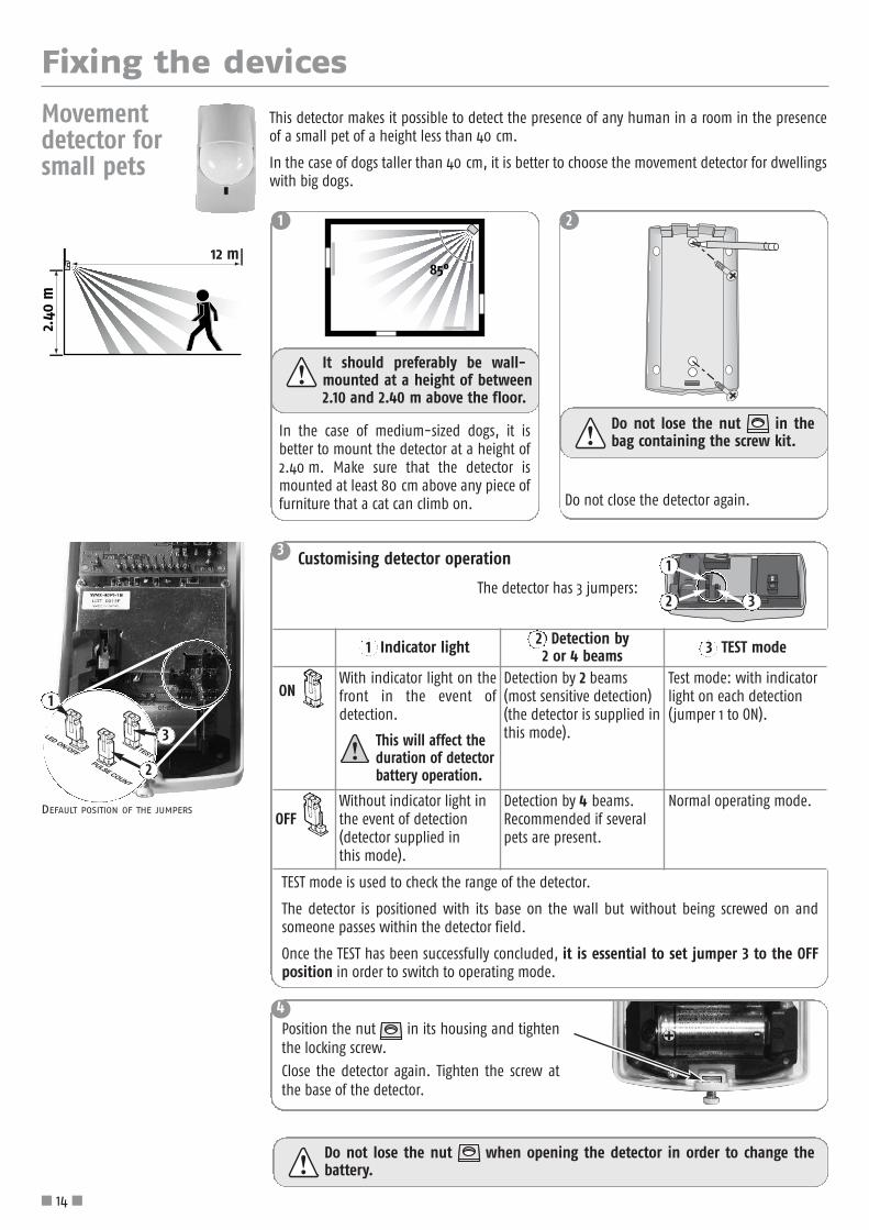
This detector makes it possible to detect the presence of any human in a room in the presenceof a small pet of a height less than 40 cm.
In the case of dogs taller than 40 cm, it is better to choose the movement detector for dwellingswith big dogs.
Movementdetector forsmall pets
1 2
It should preferably be wall-mounted at a height of between2.10 and 2.40 m above the floor.
Do not lose the nut in the bag containing the screw kit.
Do not lose the nut when opening the detector in order to change thebattery.
Do not close the detector again.
TEST mode is used to check the range of the detector.
The detector is positioned with its base on the wall but without being screwed on andsomeone passes within the detector field.
Once the TEST has been successfully concluded, it is essential to set jumper 3 to the OFFposition in order to switch to operating mode.
In the case of medium-sized dogs, it isbetter to mount the detector at a height of2.40 m. Make sure that the detector ismounted at least 80 cm above any piece offurniture that a cat can climb on.
3
4
The detector has 3 jumpers:
Customising detector operation
2
1
1 Indicator light 2 Detection by2 or 4 beams 3 TEST mode
ON With indicator light on thefront in the event ofdetection.
This will affect theduration of detectorbattery operation.
Detection by 2 beams(most sensitive detection)(the detector is supplied inthis mode).
Test mode: with indicatorlight on each detection(jumper 1 to ON).
OFF Without indicator light inthe event of detection(detector supplied in this mode).
Detection by 4 beams.Recommended if severalpets are present.
Normal operating mode.
3
Position the nut in its housing and tightenthe locking screw.
Close the detector again. Tighten the screw atthe base of the detector.
2
DEFAULT POSITION OF THE JUMPERS
1
3
� 14 �

Fixing the devices
This detects the opening of a window, the vibration of the glass in theevent of attempted intrusion and the breakage of the glass.
The detector and its magnet are mounted in the same way as for theopening detector (see page 12).
Use the double-sided adhesive strip to affix the glass breakage sensor25 mm from the corner of the window. The window should be dry andclean and preferably at a temperature of between 21 °C and 35 °C. Pressfirmly on the glass breakage sensor to ensure that it is fixed properly.
Test of detector alone: see page 12.
Opening and glassbreakage detector
This detects the acoustic frequency of breaking glass and the difference in pressure betweenthe inside and outside of the dwelling. It only protects external windows.
It must be located at least 1.20 m from sources of acoustic interference (such as television set,loudspeakers, drainpipes, doors, etc.).
Audiosonicglass breakagedetector
Max. 6 m from a window
Min. 1 m from a window
Min. 3 m
Min. 3 m
Glass breakage will be detected in a radius of:� 6 m in the case of windows made of ordinary glass or double-glazing (2.4 to 6 mm thick).
� 3.65 m in the case of toughened or laminated glass (3.2 to 6.4 mm) or anyother type of glass.
Do not position the audiosonic detector on the same wall as the windowsthat are to be protected.
1 Mount the detector on the wallapproximately 2 m above the floor.
2 Close the cover again.
DETECTOR
SENSOR
� 15 �

Fixing the devices
It is advisable to move the detector away to a wall using a 1 m cable in order toavoid fixing it to the metal, which would impair the correct propagation of theradio waves.
This is installed inside the shutter frame.
1 Use at least 3 or 4 of the screws provided to fix thesquare module flat in the centre of the frame in sucha way that the cord can travel freely with no risk ofshearing.
2 The cord’s brass outlet cylinder mustbe located as close as possible to theopening in the frame in order toavoid any risk of shearing.
3
4
The end of the cordmust be fixed bymeans of a screwpassing through theeyelet of the finalshutter strip.
Fix the detector.
Roller shutteropening detector
6 Test the detector:
Press the button on the detector: BEEP!
For a 2-minute period, the indicator on thedetector lights up every time the roller shutter isopened/closed.
Close the cover again.5
DETECTOR
DETECTOR MODULE
MODULE
CORD
SQUAREMODULE
BRASSCYLINDER
Ø 6 mm
� 16 �

Fixing the devices1 Mount the protective sheath on the cable.
3 4 Connect the detector’s 2 stripped wires to the electronic unit.
2 Fix the detector to the floor but avoid fixing it to anymetal sections.
Fix the magnet to the garage door between the two floor detector markings.
The type of fixingwill depend on the
floor material. Use differentscrews if necessary.
K ≤ 25 mm
J ≤ 35 mm
Garage dooropening detector
MAGNET
MAGNETELECTRONIC UNIT
FLOOR DETECTOR
DETECTOR
ELECTRONIC UNIT
6Test the electronic unit:
press the button on thedetector: BEEP!
For a 2-minute period, the indicatorlights up every time the garage door isopened/closed.
Close the cover again.5
Fix the electronic unit to the wall
Ø 6 mm
� 17 �
Fixing the devices1
2
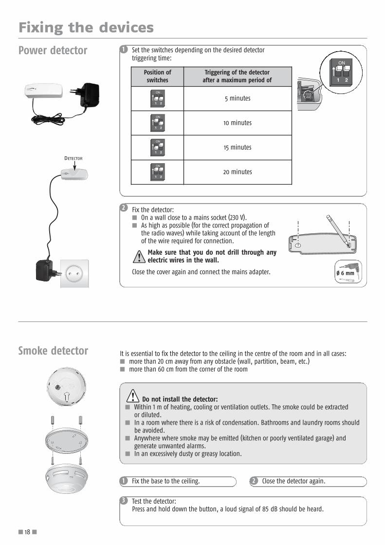
Set the switches depending on the desired detector triggering time:
Fix the detector:� On a wall close to a mains socket (230 V).� As high as possible (for the correct propagation of
the radio waves) while taking account of the lengthof the wire required for connection.
Make sure that you do not drill through anyelectric wires in the wall.
Close the cover again and connect the mains adapter.
Power detector
Position of switches
Triggering of the detector after a maximum period of
5 minutes
10 minutes
15 minutes
20 minutes
Fix the base to the ceiling.1 Close the detector again.2
Do not install the detector:� Within 1 m of heating, cooling or ventilation outlets. The smoke could be extracted
or diluted.� In a room where there is a risk of condensation. Bathrooms and laundry rooms should
be avoided.� Anywhere where smoke may be emitted (kitchen or poorly ventilated garage) and
generate unwanted alarms.� In an excessively dusty or greasy location.
Smoke detector It is essential to fix the detector to the ceiling in the centre of the room and in all cases:� more than 20 cm away from any obstacle (wall, partition, beam, etc.)� more than 60 cm from the corner of the room
3 Test the detector:Press and hold down the button, a loud signal of 85 dB should be heard.
DETECTOR
Ø 6 mm
� 18 �

Fixing the devices
Water leakage detector
1 Fix the sensor mount to the wall at floor level.
2 Mount the detector casing on the wall approximately1m above the floor.
3 Slide the sensor between the mount’s lugs until youhear a click, and pass the wire through the slots.
4 Leave the detector’s switches in the OFF position. Close the cover again.
5 Test the detector:
Pour water between the sensor’s 2 electrodes.
The indoor siren sounds quietly for 2 minutes.
To stop the alarm, press the “OFF“ button on the remote control.
At the end of the test, remove the water and dry the electrodes.
DETECTOR
MOUNT
SENSOR
If you want to control a motorised garage door or gate, it is essential to installthe keypad where you can see these automatic devices for safety reasons.
2
LCD keypad This must be inside the dwelling. It is advisable to install it near the front door.
70 mm
BOTTOM
TOPTOP
60
BOTTOM
1 Close the productagain.
Affix the tamper strip firmly against the wall.
HOLE INTAMPER STRIP
Ø 6 mm
2
Control keypad This must be inside the dwelling. It is advisable to install it near the front door or inside the garage.
51 mm
HAUTHAUT TOPTOP
47
BASBAS DOWNDOWN
1 Close the product again.
Tighten the 2 screws on the sides.
Tighten the 2 screws at the base of the casing.
Affix the tamper strip firmly against the wall.
HOLE INTAMPER STRIP
Ø 6 mm
� 19 �

Every time the alarm is armed or disarmed, the indoor siren emits one or more beeps to indicate that the instruction has beenreceived successfully.
Before closing the product again, you can cancel the beeps on the indoor siren:
Fixing the sirens
� 20 �
Indoor siren This should preferably be installedin the centre of the dwelling toensure better sound propagation.It should be at a high level whereit is difficult to access (e.g.: in thestairwell, on top of a wardrobe).
1
2
To cancel the BEEPs!
Press the button on the siren for approximately 5 secondsuntil the indicator goes off.
To restore the BEEPs!
Press the button on the siren for approximately 5 secondsuntil the indicator goes off.
You will hear a BEEP!
To be better informed of the functioning of your system, we recommend that you leave thebeeps active on at least one device.
... 5 s ... 5 s, BEEP!
Outdoor siren with flash
The outdoor siren with flash is protected against running water, condensationand humidity provided that it is mounted the right way up (flash upwards). To ensure optimum battery life, it is advisable to install it sheltered fromsunlight and water.
1During wall installation, suspend the topof the cover on the bottom of the base.
Before closing the outdoorsiren with flash again, you cancancel its beeps (see boxed text 2,indoor siren, above).
3
Close the cover again.4
Close the cover again.3
Ø 6 mm
Insert the batteries,making sure they are
the right way round (+/-).
2
Remove the batteries before installation.

Fixing the central unit/phone dialer
� 21 �
Central unit/phone dialer positioning recommendations:
Identify the composition of your installation from the 4 boxes below:
Your installation is made up of a central unit/phonedialer connected to the fixed telephone line (PSTN)without Internet access:
It should be installed close to a telephone socket,preferably in the centre of the dwelling.
Your installation is made up of a central unit/PSTNdialer with Internet access:
It should be installed near a telephone socket, thecomputer, the broadband router/modem and a mainssocket, preferably in the centre of the dwelling.
Your installation is made up of a central unit/PSTNand GSM dialer with Internet access:
It should be installed near a telephone socket, thecomputer, the broadband router/modem and a mainssocket, in a place with full GSM signal, and preferably in the centre of the dwelling.
Your installation is made up of a central unit/GSMdialer with Internet access:
It should be installed near the computer, the broadbandrouter/modem and a mains socket, in a place with fullGSM signal, and preferably in the centre of the dwelling.
MAINS SOCKET
ETHERNETCABLE
TELEPHONECABLE
GSM
ANTENNA
GSM
ANTENNA
Disconnect the mains wall socketand the telephone wall socket (if necessary) and remove one of the
four LR20 batteries before carrying out anywork inside the central unit/phone dialerand during installation.

Fixing the central unit/phone dialer
� 22 �
Common features of the installation of the central unit/phone dialer:
– If you do not want to make your system settings by computer, do not connectthe Ethernet cable or the mains cable to the IP module.
– All telephone apparatus (including fax and answering machines) must be connectedbehind the central unit/phone dialer.
– If possible, the central unit/phone dialer should be kept away from electric cables inorder to ensure better radio transmission.
– Install the central unit/phone dialer at least 60 cm off the ground.
– Do not connect the central unit/phone dialer to the back of a switchboard computer(small domestic telephone exchange).
PSTN module
1
1
3
2
POWERPOWER
2
Run the telephone cable throughthe hole provided for this purposein the bottom of the centralunit/phone dialer.
Connect one end of the telephonecable to the PSTN module.
Plug the green PTSN module, whichcan be identified by its icon showing afixed telephone , into the centralunit/phone dialer, taking care not totwist the pins.
The PSTN module must be screwed in.
If your installation does not include a PTSN module (marked PSTN: Public Switched TelephoneNetwork), skip to the next step to install the GSM module.

Fixing the central unit/phone dialer
� 23 �
We recommend that you choose a GSM operator that covers the dwelling containingthe installation.
Precautions for use The alarm unit equipped with its GSM module could interfere with the operation of medical devices (hearing aids, pacemakers, etc.).For more information, consult your doctor.
Install the central unit/phone dialer that is to hold the GSM module:� inside the dwelling only, in a zone protected by a movement detector,� in a place with full GSM signal (check this with a mobile phone, and ideally take out a contract with the same operator),� in the centre of the dwelling, for example on the ground floor if the house has a basement and one upper storey,� near a 230 V-50 Hz mains socket,� near a computer and a broadband router/modem if you wish to make settings or manage your system by computer or if you
want to use an IP camera for intrusion confirmation,� so that the cables (mains, telephone line, Ethernet, GSM antenna) come out in the direction you want them to (through the
top or bottom).
Do not install the central unit/phone dialer that is to hold the GSM module:� on a metal partition� in a damp room� near television and radio sets, as this could cause interference� near a source of gas, fuel or chemicals.
Recommendations relating to GSM subscription The GSM module placed inside the alarm unit is used to send alarm and alert messages by SMS using the dual band 900-1,800MHz GSM networks.
Before installing the GSM module, we recommend that you take out a subscription with a mobile telephony operator (Orange, SFR,Bouygues, etc.) of your choosing.
It is essential that this is a voice subscription (i.e. voice+SMS or SMS only), and not a data subscription (used to transfer data andnot voice calls).
We do not recommend the use of pre-paid cards or restricted packages on the central unit/GSM dialer. Once the credit hasrun out, if more credit is not added in time, the central unit/GSM dialer will not be able to send a message.
A personal code, known as a PIN (Personal Identification Number) linked to the SIM (Subscriber Identification Module) card, is issuedby the mobile telephony operator when the line is opened on the contract, and is used to access the network.
During programming, if the PIN is entered incorrectly three times, the SIM card on the central unit/GSM dialer is locked. The SIM cardcan be unlocked using a PUK (Personal Unlocking Key), supplied by the operator as necessary, on a mobile phone (see telephonemanual).
WarningSomfy cannot be held liable for the direct or indirect consequences of technical and contractual changes made by the GSMnetwork operator selected by the customer.
Somfy cannot be held liable for the consequences of the temporary or permanent unavailability of the GSM network selected by thecustomer for any reason.
Somfy reminds users that its systems operate using telecommunications networks (type 3 public switched telephone networks,radio, GSM, Wi-Fi, etc.), the availability of which cannot be 100% guaranteed.
GSM moduleIf your installation does not include a GSM module, skip to the Wall mounting section, page 25.
Fixing the central unit/phone dialer
� 24 �
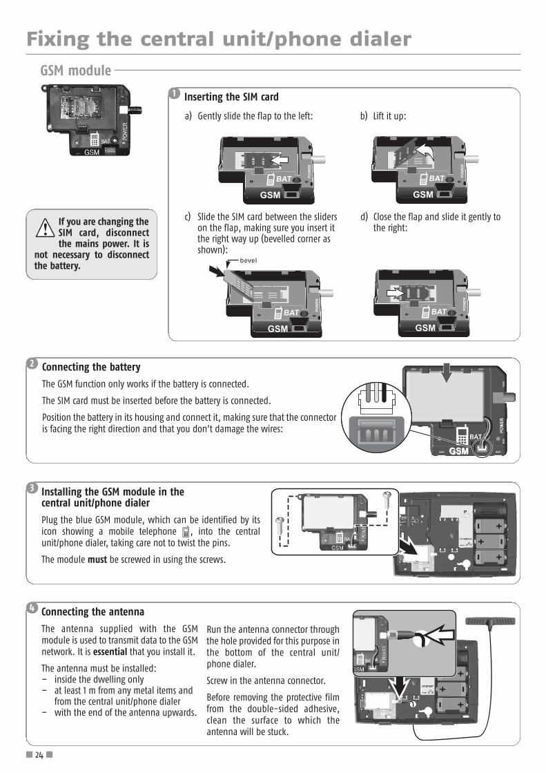
If you are changing theSIM card, disconnectthe mains power. It is
not necessary to disconnectthe battery.
GSM module
GSM
BAT POWER
1 Inserting the SIM card
a) Gently slide the flap to the left:
GSM
2 Connecting the battery
The GSM function only works if the battery is connected.
The SIM card must be inserted before the battery is connected.
Position the battery in its housing and connect it, making sure that the connectoris facing the right direction and that you don’t damage the wires:
b) Lift it up:
3 Installing the GSM module in the central unit/phone dialer
Plug the blue GSM module, which can be identified by itsicon showing a mobile telephone , into the centralunit/phone dialer, taking care not to twist the pins.
The module must be screwed in using the screws.
4 Connecting the antenna
The antenna supplied with the GSMmodule is used to transmit data to the GSMnetwork. It is essential that you install it.
The antenna must be installed:– inside the dwelling only– at least 1 m from any metal items and
from the central unit/phone dialer– with the end of the antenna upwards.
Run the antenna connector throughthe hole provided for this purpose inthe bottom of the central unit/phone dialer.
Screw in the antenna connector.
Before removing the protective filmfrom the double-sided adhesive,clean the surface to which theantenna will be stuck.
GSM
BAT POWER
c) Slide the SIM card between the sliderson the flap, making sure you insert itthe right way up (bevelled corner asshown):
GSM
BAT POWER
d) Close the flap and slide it gently tothe right:
GSM
BAT POWER
bevel

Fixing the central unit/phone dialer
� 25 �
-+
1
4
7
*R
2
5
8
0
3
6
9
#
#
1
3
2
POWERPOWER
1
You can cancel the beeps on the central unit/phone dialer (see box 2, indoor siren, page 20).2
The connection sequence depends on yourtelephone installation.Do not connect the telephone cable to an Ethernetwall socket.
Special connection situations (page 25 and 26)
The telephone cable is supplied in two parts:– a telephone cable with an RJ11 jack at each end;– a telephone socket.
Connect one end of the telephone cable to the central unit/phone dialer.
Connect the other end of the telephone cable:
A - either to the T-shaped telephone socket,
B - or directly to the wall socket if you live in a new dwelling.
A
B
TELEPHONELINE WALL
OUTLET
TELEPHONESOCKET
HEAD ENDTELEPHONE SET
TELEPHONE CABLERJ11 JACK
Use a pencil to mark the location of the fixing holes onthe central unit/phone dialer in the direction in whichyou want the cables to run (upwards or downwards).
1. Connect the Ethernet cable to thesocket on the IP module.
2. Connect the power cable to thePOWER socket on the IP module: the green indicator light flashes.
3. Reinsert the battery.
Wall mounting the central unit/phone dialer
Connecting the IP sectionIf the central unit/phone dialer does not include a PSTN module, skip to the next step on page 27.
ILLUSTRATIVE EXAMPLE WITH PSTN MODULE.
See next page

Fixing the central unit/phone dialer
� 26 �
-+
1
4
7
*R
2
5
8
0
3
6
9
#
#
12
34
-+
1
4
7
*R
2
5
8
0
3
6
9
#
#
-+
1
4
7
*R
2
5
8
0
3
6
9
#
#
If you have a broadband subscription with a conventional telephone line:
If you do not have a broadband subscription:
If your telephone only works when connected behind the broadband router/modem (fully unbundled line), you mustfollow the connection sequence:
If your telephone cable is connected directly to the broadband router/modem, modify the connections to comply with the diagram.
COMPUTER MODEMOR ANSWERING MACHINE(IF YOU HAVE ONE)
BROADBAND ROUTER/MODEM
BROADBAND FILTER
TELEPHONE LINEWALL OUTLET
TELEPHONE LINEWALL OUTLET
TELEPHONE LINEWALL OUTLET
In the event of a power failure, the fixed telephone line will not work.There will therefore be no telephone transmission and remote access to the phone dialer will not be possible.
Special connection situations (continued)
1
23
1
2
3
BROADBAND ROUTER/MODEM
BROADBAND FILTER
SOCKET SUPPLIEDBY YOUR
BROADBANDOPERATOR 1
2
3
4
Close the cover again.4If your installation does not contain a GSM module, drill the holes and fix the central unit/phone dialer to the wall.
3
HEAD ENDTELEPHONE SET
HEAD ENDTELEPHONE SET
HEAD ENDTELEPHONE SET
Ø 6 mm

Fixing the central unit/phone dialer
� 27 �
12
POWERPOWER
1If your alarm installation includes several functionsthat require a mains power supply (making settingsand remote management by computer, GSM, IOalarm), only connect one mains cable and connectit to the IP module.
2
Connect the mains adapter to a wallsocket: the green indicator light onthe GSM module comes on.
3
Reinsert the LR20 battery:
the red indicator light on theGSM module flashes.
Connecting the GSM module
If your installation does not contain anIP module, connect the mains cable tothe GSM module.
Run the Ethernet cable and the USB endof the mains cable through the holeprovided for this purpose in the bottomof the central unit/phone dialer. 1. Connect the Ethernet cable to
the socket on the IP module. 2. Connect the power cable to the
POWER socket on the IP module.
Close the cover again.5Drill the holes and fix the centralunit/phone dialer to the wall.
4
Ø 6 mm

Making the system settings
� 28 �
Radio link lost
Low battery
Cursor keys for moving up and down menus or local log
Delete an entry
Confirm an entry
Somfy 2 automatic device control
Somfy 1 automatic device control
Black programming keys
Disarm the alarm
Badge reception area
Door or window open on armingZones armedIntrusion
Icons
Text messagesover 2 lines of20 characters
Back to previous menu
Enter or exit menus
Part arm the alarm
Red or orange indicato
Fully arm the alarm
To access the menus
To move between menus, use the or + keys or type the number of the required menu + .
When you have pressed the key , there is an animated display on the screen while waiting for the menu to appear.
The display remains on the screen for 2 minutes before the screen switches off.Wait until the red indicator has stopped flashing before entering any data.
When you decide to exit the menus, press the key until the screen goes off.
OK OK
OK
Making settings using the LCD keypad
There are two ways to configure the settings of your alarm system:�using the LCD keypad, see below ;�using a computer. This method has the advantage of being an easier and faster way of configuring the
system settings; see supplementary installation manual in landscape format. However, for this to bepossible, your installation must have the central unit/phone dialer version with Internet access.
You can use the computer and LCD keypad together.You must also record a welcome message; see page 45.
The installer code permits access to your system’s settings menus. The user codes allow you to arm or disarm the system.It is essential to customise these codes on the keypad.
Press OFF on the keypad + user code 1 (factory code: 1111 ) or OFF onthe remote control keypad display: System disarmed.
Enter the menu by pressing Code ?
Type the installer code (factory code: 2 2 2 2 )A special settings display can be seen on the bottom line of thescreen. Press the black keys below the functions to activate them.
1 1
2
3
2
3
System
disarmed
Once you have connected the Ethernet cable to your broadband router/modem (installation described in the Making alarmsystem settings by computer instructions), look in menu 780 for the IP address and note it down on the memo sheet on page 8 of the Operating manual.
+
Code ?
Keypad screen
user code 1
1Language
2Codes
installer code

Making the system settings
� 29 �
Menu sequence, basic functions
It is essential to store:
- the codes,
- the phone numbers, printed on a grey background below
- the PIN,
- the date and time.
page
1 Language 12 English 30
2 Codes
20 Installer code 30
21 User code 1 30
22 User code 2 30
23 User code 3 30
24 Duress code, mute 30
25 Duress code + siren 30
26 Arm without code 30
3 Phone
31 Alarm sending
310 Voice call by PSTN (if PSTN module present)
3101 Phone number 1 31
3102 Phone number 2 31
3103 Phone number 3 31
3104 Phone number 4 31
311 Call settings3110 Call with acknowledgement 31
3111 Dial-up delay 31
312 SMS sending (by PSTN, GSM or IP)
3121 SMS number 1 32
3122 SMS number 2 32
3123 SMS number 3 32
3124 SMS number 4 32
32 SMS settings
320 SMS customisation 32
322 SMS on user code 2 32
323 SMS on user code 3 32
33 PSTN settings
330 PSTN module status 33
331 PSTN line cut 33
332 SMS sending test by PSTN 33
333 SMS sending by PSTN 33
334 Voice call test 33
34 GSM settings
340 GSM module status 34
341 GSM network failed 34
342 SMS sending test by GSM 34
343 GSM operator name 34
344 PIN entry (if GSM module present) 34
345 PUK entry 34
346 GSM periodic test 34
4 Date and time41 Date 35
42 Time 35
5 Device list 35
6 Event log 35
7 Settings 36
8 Remote monitoring 44

It is essential to customise user code 1. The installer code and the 3 user codes mustbe different.
Making the system settings
� 30 �
French is already selected.
1. Language for keypad display and voice synthesis
1Language
2Codes
User codes 1, 2 and 3 allow your customer to arm or disarm the system, customise the user codes andduress codes, store the 4 telephone numbers, the 2 SMS numbers and the date and time, view the listof devices and event log, and program the schedule for the alarm, the light, the roller shutters and thepresence simulator.
All the codes to be stored must be between 0001 and 9998. You should enter these immediatelyon the memo sheet in the operating manual.
21User code 1
... as for User code 1.22User code 2
The user code 1 factory code 1111 is displayed
1 1 1 1
Erased
The new user code 1, 4001, is stored (for example)User code 1 is erased
4001
Arming with code (default)
Arming without code
2. Customisation of codes on keypad
or
2 OK
12 OK
Empty22 OK
1004 OK
0 OK
Erasedor 0 OK
The mute duress code is used, if it is necessary when you arrive home, to disarm the alarm whileautomatically and discreetly sending an alarm message by telephone without triggering the sirens.For example, this code can be the user code + 1.
The mute duress code, 6566, is stored (for example)The mute duress code is erased
65666656 OK
24Duress code, mute
Empty42 OK
Erasedor 0 OK
The duress code + siren is used, if it is necessary when you arrive home, to disarm the alarm whileautomatically and discreetly sending an alarm message by telephone and triggering the sirens. Forexample, this code can be the user code + 2.
The duress code + siren, 4897, is stored (for example)The duress code + siren is erased
48977984 OK
25Duress code + siren
Empty52 OK
... as for User code 1.23User code 3
Empty32 OK
To arm the alarm with or without code (Arm without code):26Arm without code
1 yes, 0 no62 OK 0 OK
1 OK
The installer code makes it possible to access the menus and configure your alarm system. It is essentialto customise your installer code and note it here: .................................................................
The new installer code, 2148, is stored (for example)
21488412 OK
20Installer code
The factory installer code 2222 is displayed
222202 OK

Making the system settings
3Phone
3101 Phone number 1 Empty
3 OK
101 OK
3102 Phone number 2 Empty201 OK
2784690599 OK
0 OK
If “Phone number 1“ does not respond or if the recipient doesnot press “9“ to confirm receipt of the message then the nextnumber is dialled.
... as for menu 3101
3103 Phone number 3 Empty301 OK ... as for menu 3101
3104 Phone number 4 Empty401
3
3
3
3 OK
1 yes, 0 no0113 OK
101113 OK
... as for menu 3101
Inform the recipients of alarm messages that their phone numbers have been stored.
If any of the recipients of an alarm message have a fully unbundled line then they may not always be ableto confirm receipt of the message by pressing “9“ on their telephone.
You can choose that recipients do not have to acknowledge successful receipt of an alarm message; see menu 3110.
The new phone number is stored (for example) (max. 15 digits)The number is erased
9950964872
Erased
3. Phone
Num 1 Num 1
Num 2 Num 2
Num 3 Num 3
Num 4 Num 4
Tempo 5'Tempo 4'Tempo 3'Tempo 2'Tempo 1'
To avoid immediate dial-up if an alarm is triggered by accident :3111 Dial-up delay
Setting of the delay before dial-up in the event ofintrusion (from 0 to a maximum of 30 seconds), 10 seconds by default
To store:- either 4 telephone numbers for sending synthesised voice alarm messages by fixed telephone
line (PSTN),– or 4 SMS numbers for sending alarm SMSs by GSM,– or a combination of both, if the installation includes the PSTN module + the GSM module.
31 Alarm sending
To store 4 telephone numbers for sending synthesised voice alarm messages to neighbours’, familymembers’ or friends’ mobile or fixed telephones:310 Voice call by PSTN
13 OK
013 OK
3110 Call with acknowledgement
Used to make settings for sending alarm messages, either by fixed line or GSM.
So that the recipient of a synthesised voice alarm message performs remote acknowledgment (by pressing “9“) or does not acknowledge receipt of an alarm message:
311Call settings
113 OK
No acknowledgement0 OK
Acknowledge with “9”1 OK (default)
If the recipient of a synthesised voice alarm message has a fully unbundled telephone line, it is essentialto deactivate the acknowledgement of the alarm message. In this case the phone dialer will only cyclethrough the 4 stored telephone numbers once (menus 3101 to 3104).
� 31 �

Making the system settings
� 32 �
1 3 DEF2 ABC
4 GHI 6 MNO5 JKL
7 PQRS 9 WXYZ8 TUV
# 0 +
1 3 DEF2 ABC
4 GHI 6 MNO5 JKL
7 PQRS 9 WXYZ8 TUV
# 0 +
OLIVIER’salarm system.On 19/07 at 17:02,Disarmed -user code 2
Press successively on the same alphanumeric key to select the letter of your choice.
Customisation023 OK
REIVILO OK
0 OK
Entry of a name ordescription (maximum15 characters)The custom setting is erased
OLIVIER
Erased
Used to customise alarm SMS sending.32 SMS settings
To customise the sender of the SMS:320 SMS customisation
23 OK
3121 SMS number 1 Empty121 OK
3122 SMS number 2 Empty221 OK
2184690670 OK
0 OK
... as for menu 3121
3123 SMS number 3 Empty321 OK ... as for menu 3121
3124 SMS number 4 Empty421
3
3
3
3 OK ... as for menu 3121
The new phone number is stored (for example) (max. 15 digits)The number is erased
0760964812
Erased
To store 4 SMS numbers for sending alarm SMSs by the fixed telephone line (PSTN) or GSM, toneighbours’, family members’ or friends’ mobile or fixed telephones (for fixed telephones, the alarmSMS will be voice synthesised by the operator):
312 SMS sending
213 OK
To receive an SMS after the system has been armed/disarmed by user code 3 (stored in menu 23).
323 SMS on User code 3
1 yes, 0 no323 OK As for menu 322
To receive an alert SMS after the system has been armed/disarmed by user code 2 (stored in menu 22)(only if the system was fully armed). Only the 1st SMS number will be alerted.Receipt of the alert SMS will only be possible if:– menu 333 is activated, or– the central unit/phone dialer contains the GSM module.For example: to be informed when your child gets back from school or of the arrival/departure of thecleaner.
(default)
322 SMS on User code 2
1 yes, 0 no223 OK
0 OK
1 OK
No SMS sent
SMS sent OK

Making the system settings
� 33 �
Present Missing033 OK
Used to check the status of the fixed telephone line and perform sending tests before the systemis armed for the first time.
33 PSTN settings
Used to check whether or not the PSTN module is connected:330 PSTN module status
33 OK
If your fixed phone line does not function during a power failure (if you have a broadband router/modem),do not activate phone line cut supervision (to avoid false alarms).
For the sending of an alarm message and the triggering of the sirens if the fixed phone line is cut (only if the system is fully armed):
The SMS sent will be “SMS sending test“.
331 PSTN line cut
1 yes, 0 no133 OK
0 OK
1 OK
No supervision
Supervision OK
To be informed by the sending of an alert SMS by the fixed phone line (PSTN) when the system isarmed/disarmed or an alarm SMS in the event of an alarm. Only works with a France Telecom line.The sending of alert SMSs on User codes 2 and 3 depends on this setting; see menus 322 and 323.
(default)
333 SMS sending by phone
1 yes, 0 no333 OK
0 OK
1 OK
No SMS sent
SMS sending
or
Sending test OK233 OK
To check correct sending of an SMS by the fixed phone line (PSTN):332 SMS sending test by PSTN
Only the 1st number is called. The message delivered by voice synthesis will be: “Press 9 to send alarm message“.
When the recipient presses 9, the central unit/phonedialer hangs up.
Sending test OK433 OK
To check correct sending of synthesised voice alarm message by the fixed phone line (PSTN).334 Voice call test

Making the system settings
� 34 �
GSM OFF
GSM not initialised
GSM PIN rejected
GSM SIM access prob.
GSM PIN error
Connecting
Connection failed
GSM connected to network 3/5
GSM missing
043 OK
Used to identify the name of the strongest GSM network at the installation, find out the status ofthe GSM line, make SIM card settings and send a test alarm SMS to the 1st number.
34 GSM settings
To find out the status of the GSM network at any time.List of order of messages:
340 GSM module status
43 OK
There is a power failure.
(fleeting message)
A new PIN must be entered.
The number from 0 to 5 indicates network strength,with 5/5 being maximum strength.No GSM module detected.
The SMS sent will be “SMS sending test“.Sending test OK243 OK
To check correct sending of a test SMS by GSM. This test will be sent to the 1st SMS number stored (see menu 3111).
342 SMS sending test by GSM
Before the SIM card is inserted into the GSM module onthe phone dialer, the name of the operator with thestrongest signal will be displayed.Once the SIM card has been inserted and a valid PINentered, the name of the SIM card operator will bedisplayed.
The PUK is erased.
Operator name343 OK
To check the operator’s name.343 GSM operator name
XXXX443 OK
Enter the 4-digit PIN shown on the subscription contract, if the PIN is activated on the SIM card.If you enter the PIN incorrectly 3 times, find out the PUK from the SIM card support card, or ask yourGSM operator for it so that you can unlock the SIM card.
344 PIN entry
XXXX543 OK
The PUK should only be entered if the SIM card is locked.Enter the PUK given to you by your GSM operator.
345 PUK entry
Used to set the length of time in minutes (between 0 and 240 minutes) after which you wish to bealerted by SMS by the fixed line or IP (if you have opened an account).
15 (15 minutes by default); the message sent will be“GSM network fault“Function deactivated.
341 GSM network lost
15143 OK
0 OK
To receive an automatic SMS at midday by GSM confirming satisfactory operation of the GSM function.Only the 1st SMS number will be alerted.
Enter the number of days between 1 and 240 days (14 days by default). The SMS sent will be “GSM periodic test“.No GSM periodic test
346 GSM periodic test
14643 OK
0 OK
Erasedor 0 OK

Making the system settings
� 35 �
This menu makes it possible to timestamp alarm messages.
If the installation includes an IP module and your central unit/phone dialer is connected to abroadband router/modem, the central unit/phone dialer will automatically manage thesummer/winter clock change.
4Date and time 4 OK
4. Storing the date and time
This menu can be used to view the last 500 events (alarms, faults, arming/disarming, radio link lost,start of sending of alarm messages, end of sending of alarm messages, tampered device, code entry,low batteries) together with their date and time of occurrence.
6Event log
6. Log of recent events
41Date
Date: 01/01/201014 OK
01021042 OK The new date is stored (for example)24/01/2010
42Time
Time: 12:0024 OK 0580 OK The new time is stored (for example)08:50
Disarm
161166Z:ABC02/0116h36
6 OK
To switch to another event: or keys
Display of last event (for example)
This menu is used to:- define the name of each device in order to fully customise the installation and identify devices
easily in the event of a fault or loss of radio link,- be aware of the status of each device in the system at all times (battery level, alarm, tamper
switch, radio link) by switching between them using the or keys.
5 Device list
5. Customising devices
Switch to another device: or keys
or
Phone dialer 523456 Z: SYSDevice name?
5 OK
OK
XXXXX OK
0 OK
Customise the name of this device
Enter the name (max. 15 characters), for example: garage door
The device is no longer stored in the system
XXXX
Erased
SERIALNUMBER
SYSTEMZONE
PRODUCT

Making the system settings
� 36 �
Menu sequence (continued), Advanced functions
7 Settings
71 Entry delay 3772 Fault erasing 37
73 Sound options
731 Kiela OK 37732 Beeps on phone dialer 37733 Integrated siren 37734 High on part arming 37735 Kiela level 37736 Siren level 38
74 Jamming detection 38
75 Advanced functions
751 Call on part arming 38752 CS lock 38753 Opening memory 38754 Closing memory 38755 Version 38756 Power failure on central unit/phone dialer 38
76 Control of automatic devices
761 Programming of automatic devices
7611 Shutter prog. 397612 Light prog. 397613 Gate prog. 397614 Garage door prog. 39
762 Somfy 1 key 39763 Somfy 2 key 39
764 Shutters down7641 Shutters on intrusion 407642 Shutters on arming 40
765 Shutters up7651 Shutters on smoke 407652 Shutters on disarming 40
766 Light
7661 Light on intrusion 407662 Light on arming 407663 Light on disarming 407664 Light timer 40
77 Time programming
771Automatic arming
7711 Arm. Time 1 417712 Zones Armed 1 417713 Arm. Time 2 417714 Zones Armed 2 417715 Select days 417716 Auto arm beep 41
772 Automatic light
7721 Light ON 1 427722 Light OFF 1 427723 Light ON 2 427724 Light OFF 2 427725 Select days 427726 Pres Sim Delay 42
773Automatic shutters
7731 Shutters up 437732 Shutters down 437733 Select days 437734 Pres Sim Delay 43
774 Presence simulation 43775 Shutter delay 43
78 IP settings780 Central unit/phone dialer IP address 44781 Router/modem IP address 44
8 Remote monitoring 44
page

Making the system settings
� 37 �
(45 seconds by default)
7. Settings for advanced functions
The new delay period is stored
7 Settings
Used to set the entry delay for the intrusion detectors in zone A with delayed triggering, with avalue of 1 to 60 seconds before triggering of the alarm:
71Entry delay
45 Interval:
XX
7 OK
17 OK
27 OK
XX OK
To erase all of the faults on the LCD keypad and switch off the orange indicator on the LCD keypad:72Fault erasing
To cause the indoor siren to emit a CHIME on the opening of a door protected by anopening detector in zone A (with delayed triggering) when the system is partarmed (zone A):
The following menus are used to customise the BEEPS! and the functioning of the installation’s sirens.73Sound options
731Kiela OK
1 yes, 0 no
37 OK
137 OK
0 OK
1 OK
no CHIME (default)
CHIME
OFF
ON
To set the sound level of the CHIME and the BEEP! on the sirens :Anything detected by an opening detector in zone A with delayed triggering results in aCHIME on the indoor siren (Kiela function) if the system is part armed and in zone A and ifthe Kiela function is selected in menu 731 above.
735KIELA level
Level 1, 2 or 3537 OK
(default)
To cause the central unit/phone dialer to emit a BEEP! on arming/disarming:732Phone dialer beeps
Do not change this menu.733Integrated siren
1 yes, 0 no237 OK
0 OK
1 OK
no BEEP!
BEEP! (default)
OFF
ON
Used to customise the functioning of the sirens when the system is part armed :734High on part arming
1 yes, 0 no437 OK
0 OK
1 OK
no outdoor siren and indoor siren low.high outdoor siren and indoor siren(default) if high level selected in menu 736.
OFF
ON
1 OK
2 OK
Low level
Medium level
3 OK High level

Making the system settings
� 38 �
To set the sound level of all the sirens in the installation:736Siren level
Level 1, 2 or 3637 OK
To cause a message to be entered in the event log on the LCD keypad if jamming is detected:74Intf detect.
1 yes, 0 no No intf. detect47 OK 0 OK
Jamming detect. OK1 OK
No message if jamming is detected(default)Message if jamming is detected
To cause or inhibit the sending of an alarm message when the system is part armed:
75Advanced functions
751Call on part arming
1 yes, 0 no
57 OK
157 OK
0 OK
1 OK
No message is sent
Message is sent (default)
If you have a remote monitoring contract, you should store a locking number sent toyou by the remote monitoring centre:
752CS lock
CS Number257 OK
Used to cause the central unit/phone dialer to enter storage mode for 2 minuteswhen additional devices are stored, when the central unit/phone dialer is alreadyinstalled and the system is already operational:
753Opening memory
Memory open357 OK
XXXXXXXXXX OK XXXXXXXXXX The number is stored
“Memory open“ is displayed and thekeypad then goes off. You have 2 minutes to store a device.
To terminate storage mode:754Closing memory
Reading the version.755Version
Memory closed457 OK “Memory closed“ is displayed and thekeypad then goes off. Storage mode has ended.
(default)
1 OK
2 OK
Low level
Medium level
3 OK High level
To be informed by SMS of a power failure on the central unit/phone dialer:
Setting of the delay before the sending of a “Power failure“ SMS, between 0 and 240 minutes (15 minutes by default).Function deactivated.
756 Power failure
15657 OK
0 OK

Delete the assignment of key (default)The key will control the roller shuttersThe key will control the lightingThe key will control the gateThe key will control the garage door
763Somfy key 2
0367 OK
0 OK
1 OK
2 OK
3 OK
4 OK
This menu allows you to assign a Somfy automatic device to the key on theLCD keypad (and all the LCD keypads in the installation):
Making the system settings
� 39 �
Delete the assignment of key (default)The key will control the roller shuttersThe key will control the lightingThe key will control the gateThe key will control the garage door
To store the roller shutter receiver:- open the memory of the roller shutter receiver (refer to the
corresponding instructions);- press
This menu is used to:- store Somfy automatic devices (roller shutters, gate, garage door) or the Somfy light receiver;- assign the and keys on the LCD keypad to these automatic devices;- to create roller shutter up/down scenarios or light on/off scenarios.
First of all, read the instructions for the Somfy motor/receiver that you want to trigger (see section “Storingremote controls“).
76Automatic device command
761Programming of automatic devices67 OK
7611Shutter prog167 OK
1167 OK The roller shutter receiver is stored
To store the light receiver:- open the memory of the light receiver (refer to the corresponding
instructions);- press
7612Light prog.
2167 OK The light receiver is stored
To store a garage door automatic device:- open the memory of the garage door automatic device (refer to the
corresponding instructions) ;- press
7614Garage door
4167 OK The garage door automatic device is stored
To store the gate automatic device:- disconnect the central unit/phone dialer telephone cable on the wall side;- deactivate the central unit/phone dialer tamper switch by pressing OFF on
the remote control until the indicator goes off;- you have 2 minutes to open the central unit/phone dialer and remove it
from the wall;- disconnect all the cables inside the central unit/phone dialer;- open the cover of the gate automatic device;- move the centre of the central unit/phone dialer close to the gate
electronic unit, under the cover;- open the memory of the gate automatic device (refer to the corresponding
instructions) ;- press
7613Gate prog.
3167 OK The gate automatic device is stored
This menu allows you to assign a Somfy automatic device to the key on theLCD keypad (and all the LCD keypads in the installation):
762Somfy key 1
0267 OK
0 OK
1 OK
2 OK
3 OK
4 OK
Making the system settings
� 40 �
The roller shutters do not come up if smoke is detected (default)
The roller shutters come up when smoke is detected
No command (default)
Roller shutters come down if the system is fully armed (zones A+B+C)
Roller shutters come down if the system is part or fully armed
The roller shutters do not come down in the event of intrusion (default)
The roller shutters come down in the event of intrusion
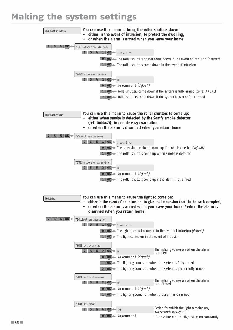
You can use this menu to bring the roller shutters down:- either in the event of intrusion, to protect the dwelling, - or when the alarm is armed when you leave your home
764Shutters down
7641Shutters on intrusion
7642Shutters on arming
467 OK
0
1 yes, 0 no
2467 OK
1467 OK
0 OK
1 OK
0 OK
1 OK
1 yes, 0 no
0 OK
1 OK
The light does not come on in the event of intrusion (default)
The light comes on in the event of intrusion
1 yes, 0 no
0 OK
1 OK
2 OK
No command (default)
The roller shutters come up if the alarm is disarmed
You can use this menu to cause the roller shutters to come up:- either when smoke is detected by the Somfy smoke detector
(ref. 2400443), to enable easy evacuation, - or when the alarm is disarmed when you return home
765Shutters up
7651Shutters on smoke
7652Shutters on disarming
567 OK
02567 OK
1567 OK
0 OK
1 OK
No command (default)
The lighting comes on when the system is fully armed
The lighting comes on when the system is part or fully armed
The lighting comes on when the alarm is armed
You can use this menu to cause the light to come on:- either in the event of an intrusion, to give the impression that the house is occupied,- or when the alarm is armed when you leave your home / when the alarm is
disarmed when you return home
766Light
7661Light on intrusion
7662Light on arming
7663Light on disarming
7664Light timer
667 OK
02667 OK
1667 OK
0 OK
1 OK
2 OK
No command (default)
The lighting comes on when the alarm is disarmed
The lighting comes on when the alarm is disarmed03667 OK
Period for which the light remains on, 120 seconds by default.If the value = 0, the light stays on constantly.
1204667 OK
0 OK
No command0 OK
1 OK

Making the system settings
� 41 �
To programme one or two automatic armings (for example: at 8:50 in the morning,when everyone has left the house, or at 23:00 in the evening when everyone is in bed).
To cancel the time programming, set all the days to “0“.
To store the time of the 1st automatic arming of the alarm:
You can use this menu to programme the automatic arming of the system and simulate presence in thedwelling (lighting or roller shutters).
77Time prog.
771Arming77 OK
7711On time 1
To select the zone or zones to be armed at the 1st automatic arming time:
7712Zones Armed 1
177 OK
(default)
Time of 1st automatic arming stored08:50
18:30
0580 OK
1177 OK
To store the time of the 2nd automatic arming of the alarm:7713On time 2
(default)
Time of 2nd automatic arming stored23:00
18:30
0032 OK
3177 OK
To select the days for the 1st and 2nd automatic arming:7715Select days
For example: to arm the alarm onTuesdays, Fridays and Saturdays but notthe other days
“1“ equals a selected day, otherwise “0“(by default, every day)
MTWTFSS: 0 100 1 10
MTWTFSS: 1 1 1 1 1 1 1
0110010 OK
5177 OK
To cause or inhibit a BEEP! when the alarm is automatically armed,and set the interval between this BEEP! and the automatic arming:
7716Auto arm beep
Setting of delay between 1 and 120 seconds
(zero seconds and no BEEP! by default)
Interval:
XXX
0
XXX OK
6177 OK
Delete the programming of the 1st automatic arming
Zone A
Zone B
Zones A and B
Zone C
Zones A and C
Zones B and C
Zones A, B and C (full arming)
Select zone:02177 OK
To select the zone or zones to be armed at the 2nd automatic arming time:
7714Zones Armed 2
Select zone: as for menu 771204177 OK
0 OK
1 OK
2 OK
3 OK
4 OK
5 OK
6 OK
7 OK

Making the system settings
� 42 �
For example: if you have set a delay of 15 minutes for a programmed light on time of 19:00,the actual light on time will be between 19:00 and 19:15 and at a different time for eachchosen day.
To cancel light programming 1, enter identical on and off times.
To simulate a presence by programming the switching on and off of a light.
Time light is switched on, time slot 1:
772Light
7721Light ON 1277 OK
Light on time 1 stored06:45
07:30
5460 OK
1277 OK
Time light is switched off, time slot 1:7722Light OFF 1
Light on time 1 stored08:15
07:30
5180 OK
2277 OK
To cancel light programming 2, enter identical on and off times.
Time light is switched on, time slot 2:7723Light ON 2
Light on time 2 stored19:25
18:30
5291 OK
3277 OK
Time light is switched off, time slot 2:7724Light OFF 2
Light on time 2 stored22:30
18:30
0322 OK
4277 OK
To cancel the time programming, set all the days to “0“.
To select the days on which presence is to be simulated using a light:7725Select days
For example: to simulate presence onMondays, Wednesdays and Saturdays but not on the other days
“1“ equals a selected day, otherwise “0“(by default, every day)
MTWTFSS: 10 100 10
MTWTFSS: 1 1 1 1 1 1 1
0100101 OK
5277 OK
To set the delay between the programmed and actual on and offtimes randomly:
7726Pres Sim Delay
Setting of delay between 1 and 59 minutes
(zero minutes by default)
Interval:
XX
0
XX OK
6277 OK

Making the system settings
� 43 �
To cancel the programming, enter identical up and down times.
PRESENCE SIMULATION USING ROLLER SHUTTERS: to simulate a presence by programmingthe opening and closing of roller shutters.
Time at which the roller shutters come up:
773Roller shutters
7731Shutters up377 OK
Up time stored08:30
18:30
0380 OK
1377 OK
Time at which the roller shutters come down:7732Shutters down
Down time stored20:15
18:30
5102 OK
2377 OK
For example: if you have set a delay of 15 minutes for a programmed up time of 08:30, the actual up time will be between 08:30 and 08:45 and at a different time for eachselected day.
To cancel the presence simulation, set all the days to “0“.
To select the days on which presence is to be simulated by means ofthe opening and closing of roller shutters:
7733Select days
For example: to simulate presence on Mondays, Wednesdays and Saturdays butnot on the other days
“1“ equals a selected day, otherwise “0” (by default, every day)
MTWTFSS: 10 100 10
MTWTFSS: 1 1 1 1 1 1 1
0100101 OK
3377 OK
To set the delay between the programmed and real up and downtimes randomly:
7734Simulat. delay
Setting of delay between 1 and 59 minutes
(zero minutes by default)
Interval:
XX
0
XX OK
4377 OK
To set the command delay on triggering of the outdoor movement detector,between 1 and 120 seconds:
775Shutter delay
The new value is stored
(2 seconds by default)
Interval:
XX
2
XX OK
577 OK
PRESENCE SIMULATIONS ASSOCIATED WITH SYSTEM STATUS: to assign a system status for whichthe presence simulations (light and roller shutters) programmed above are to take effect.
774Presence simul.
Simulation occurs whether or not thesystem is armed (default)
Simulation only occurs if the system is fully armed
Simulation only occurs if the system is inpart or fully armed
Simulation only occurs if the system is disarmed
(default)
Activated
0
0
0 OK
Activated
1
1 OK
Activated
2
2 OK
Activated
3
3 OK
477 OK

Making the system settings
� 44 �
IP address of the central unit/phone dialer (record on the memo sheet in the operating manual).
780Phone dialer IP address
IP address of the broadband router/modem (record on the memo sheet in the operating manual).
781Router IP address
This menu is used to read the IP address of the central unit/phone dialer and the IP address of thebroadband router/modem.
78IP settings
8Remote monitoring
Type code 81CS protoc Enter protocol
8 OK
9876 OK 18 OK
82Regist. No. Type the number28 OK
83CS code Type code38 OK
84Phone no. 1 Type number48 OK
85Phone no. 2 Type number58 OK
86Periodic call Enter protocol68 OK
87Call cycle Enter protocol78 OK

� 45 �
Recording a customised alarm message announcement
SettingSelectmenu
Entry of message Action
Record a welcome message 3 “This call is from Mr Dupont’s alarm system...“ # Listen to the recorded message
Listen to the recorded message 4 Listen to the recorded message
Record the welcome message
The phone dialer specifies the system status:
No entries are accepted while a voice message is being issued.
The customised alarm message is used to introduce the alarm message sent by voice synthesis. It can only be recorded remotelyas follows:
Connect to the phone dialer from another telephone line or mobile telephone
Press OFF + enter user code 1 on the LCD keypad (or OFF on the remote control).
Zone A and/or Zone B and/or Zone C armed(or) System armed(or) System disarmed
andAlarm stored for Zone A and/or Zone B and/or Zone C and/or Technical Unit (domestic fault) or System (or) No alarm stored
1 3 DEF2 ABC
4 GHI 6 MNO5 JKL
7 PQRS 9 WXYZ8 TUV
# 0 +
If the code is incorrect, the phone dialer will hang up and it is necessary to start again.
1 3 DEF2 ABC
4 GHI 6 MNO5 JKL
7 PQRS 9 WXYZ8 TUV
# 0 +
1 3 DEF2 ABC
4 GHI 6 MNO5 JKL
7 PQRS 9 WXYZ8 TUV
# 0 +
1 3 DEF2 ABC
4 GHI 6 MNO5 JKL
7 PQRS 9 WXYZ8 TUV
# 0 +
Dial the telephone number of the line towhich the phone dialer is connected.
Wait for it to ring 3 times...
Dial the same telephonenumber
Wait for it to ring 2 times...
Enter the installer code
Wait for 10 s
Hang up
1 3 DEF2 ABC
4 GHI 6 MNO5 JKL
7 PQRS 9 WXYZ8 TUV
# 0 +
This message can only be recorded if your central unit/phone dialer is equipped with a PSTN module.

Testing the installation
� 46 �
Press
Type the duress code + siren
(must be stored inmenu 25)
Testing the entire system
Testing the phone dialer only
Fully arm the alarm and then leave the house.
To test for correct sending of an SMS to the 4 numbers stored: On the LCD keypad:1 - Press OFF2 - Enter the duress code, mute (should be stored in menu 24). The call cycle for sending the alarm message to the 4 phone
numbers starts.3 - Stop the alarm message call cycle by pressing the OFF key on the remote control or OFF + user code 1 on the keypad.
To test for correct sending of an SMS by the fixed phone line, enter the following on the LCD keypad:
After the 2 minute exit delay, open all the doors and windowsthat are equipped with opening detectors. Move in front of at least one movement detector.
The sirens are triggered. Allow the sirens to ring for at least theprogrammed telephone dial-up delay.
The phone dialer starts dialing.
The roller shutters come down and the lights come on if thesefunctions are programmed.
Disarm the alarm by pressing the OFF key on the remote control. The call cycle stops with the exception of the current call.Identify the detectors that triggered the alarm (see page 50).
Sous surveillance
Testing the detectorsWith the alarm disarmed, press the detector
For a 2-minute period, the indicator onthe detector lights up on each detection
If a problem occurred during the test, refer to page 52,Troubleshooting.
…BEEP! …BEEP!
Testing the sirens and the phone dialer
The sirens are activated for2 minutes and the phone dialerpicks up the line
You can interrupt the sirens and the call cycle by disarming the alarm. To do this, press OFF on the remotecontrol or OFF + user code 1 on thekeypad.
Door opening/closing
Movement in front of the detector
For the outdoor movement detector, refer to the corresponding instructions.
3 x BEEP! ... 2 mins, BEEP!
or
3
Hold down the ON key until theindicator goes off.
1
1
2
2
Sous surveillanceSous surveillance
Arm the alarm
The SMS sent will be “SMS sending test“.The test will be sent to the 1st SMS number stored.
Sending test OK233 OK
To test for correct sending of an SMS by GSM, enter the following on the LCD keypad:
The SMS sent will be “SMS sending test“. This test will besent to the 1st SMS number stored.
Sending test OK243 OK

� 47 �
Remote settings via telephone
Connect to the phone dialer from a telephone outside the dwelling: proceed as described on page 45. If the code is correct, the phone dialer specifies the system status; otherwise it hangs up.
No entries are accepted while a voice message is being issued.
Making settings remotely via telephone is particularly recommended if settings are changed later after initial installation.
The “ Remote settings via telephone “ function is only guaranteed for France Telecom lines.
It is only possible if your customer agrees. The customer must have entered OFF + user code 1 on his/her LCDkeypad before you enter your installer code remotely.
Type of stored messageCategory + Group
Alarm
or
Battery low
or
Radio link lost
AD Zone A - With delayA Zone A - ImmediateB Zone B - ImmediateC Zone C - Immediate
SYS System (keypads, sirens, phone dialer, disconnected IP camera)TEC Technical (smoke, water leakage or power detectors)
Viewing stored information when the orangeindicator flashes on the LCD keypad
To erase the stored faults and switch off the orange indicator on a keypad, fully arm the alarm and then disarm itusing that keypad, or go to menu 72 “Fault erasing“.
The battery and radio link lost faults will reappear if they have not been corrected.
On the LCD keypad
If a fault is detected, the orange indicator flashes and the fault is indicated on the screen.
Enter the log, type in the installer code, press and view menu 5 “Device list“ for moreinformation.
The character is the separator, and the character # is used to confirm.
Setting Selectmenu
Entry of setting (format/example) Voice message (example) / Action
Record the date and time 1DDMMYYYYHHMM#
e.g.: 120620080926#your entry is one, asterisk, one, two, zero, six, two, ...
hash
Record a phone number
2
1 type the number (max. 15 digits)e.g.: 0723456789
# First alarm phone number
2 # Second alarm phone number
3 # Third alarm phone number
4 # Fourth alarm phone number
x # Erases the number stored under phone number “x“
Record a welcome message 3“This call is from Mr Dupont’s
alarm system...“# Listen to the recorded message
Listen to the recorded message 4 Listen to the recorded message
Customise the installer code5
0 type the 4-digit code
# Entry of the installer code
Customise the user code 1 # Entry of the user code

Summary of system operation
� 48 �
Syst
em
trig
geri
ngIn
door
sire
ntr
igge
red
Outd
oor
sire
n w
ith
flash
tri
gger
edLi
ght
trig
gere
d(1
20 s
)
Rolle
r sh
utte
rtr
igge
red
Tele
phon
e tr
ansm
issi
on o
f a
mes
sage
Stor
edSi
ren
(aft
er 1
0 s)
Flas
h(1
20 s
)Vo
ice
SMS
Rem
ote
mon
.(if
regi
ster
ed)
Depe
ndin
g on
set
tings
In all cases
Syst
em a
rmin
gBe
eps
or s
erie
s of
bee
ps
(dep
endi
ng o
n sir
en s
ettin
g)Be
eps
or s
erie
s of
bee
ps
(dep
endi
ng o
n sir
en s
ettin
gs)
NoDe
pend
ing
onse
tting
sDo
wn
Yes/N
ode
pend
ing
on se
tting
sNo
Depe
ndin
g on
setti
ngs
NoYe
s
Syst
em d
isarm
ing
Beep
or s
erie
s of
bee
ps
(dep
endi
ng o
n sir
en s
ettin
gs)
Beep
s or
ser
ies
of b
eeps
(d
epen
ding
on
siren
set
tings
)No
Depe
ndin
g on
setti
ngs
Dow
n Ye
s/No
depe
ndin
g on
setti
ngs
NoDe
pend
ing
onse
tting
sNo
Yes
Dure
ss a
larm
with
sire
nYe
sYe
sYe
sYe
sde
pend
ing
on se
tting
sDo
wn
Yes/N
ode
pend
ing
on se
tting
sYe
s (if
no CS
), de
pend
ing
on se
tting
sDe
pend
ing
onse
tting
sYe
sYe
s
Dure
ss a
larm
with
out s
iren
NoNo
NoNo
NoYe
s(if
no C
S)Ye
sYe
sYe
s
Open
ing
of d
evice
afte
r pro
long
ed O
FFNo
NoNo
NoNo
NoNo
NoYe
s
Batte
ry e
rror
in d
evice
NoNo
NoNo
NoNo
Yes,
to
the
1stnu
mbe
rYe
s(on
per
iodi
c te
st)
Yes
Devi
ce ra
dio
link
lost
NoNo
NoNo
NoNo
Yes,
to
the
1stnu
mbe
rYe
s(on
per
iodi
c te
st)
Yes
Radi
o ja
mm
ing
(if fu
nctio
n co
nfirm
ed)
NoNo
NoNo
NoNo
NoNo
Yes
Trig
gerin
g of
wat
er
leak
age
dete
ctor
Yes
(low
)No
NoNo
NoYe
s(if
no C
S)Ye
sYe
sYe
s
Pow
er fa
ilure
det
ectio
n fu
nctio
n (c
entra
l uni
t or d
etec
tor)
Serie
s of
bee
ps a
fter
dete
ctor
del
ayNo
NoNo
NoYe
s(if
no C
S)Ye
s, to
the
1stnu
mbe
rYe
sYe
s
Trig
gerin
g of
sm
oke
dete
ctor
Yes
Yes
Yes
NoUp
Yes
/No
depe
ndin
gon
set
tings
Yes(
if no
CS)
Yes
Yes
Yes
GSM
net
wor
k fa
iled
NoNo
NoNo
NoNo
Yes b
y PS
TN o
r by
GSM
whe
n ne
twor
kco
vera
ge re
turn
sNo
Yes
Disarmed
Unau
thor
ised
open
ing
of d
evice
Yes
low
or h
igh
depe
ndin
g on
set
tings
Yes/
No
depe
ndin
g on
set
tings
If ou
tdoo
r sire
ntri
gger
ed
Yes/
No
depe
ndin
g on
setti
ngs
Dow
n Ye
s/No
depe
ndin
g on
setti
ngs
Yes/
No
depe
ndin
g on
setti
ngs
(if n
o CS
)Ye
sYe
sYe
s
Fixe
d ph
one
line
cut (
if fu
nctio
n ac
tivat
ed in
Men
u 33
1
and
the
line
has
been
pre
sent
at l
east
onc
e)No
NoNo
NoNo
-No
-Ye
s
Part armed
Trig
gerin
g of
a d
etec
tor
in z
one
A w
ith d
elay
Yes
high
/low
de
pend
ing
on s
ettin
gsPo
ssib
ility
of K
iela
bee
psde
pend
ing
on s
ettin
gs
Yes/
No d
epen
ding
on
setti
ngs
No if
KIE
LA
If ou
tdoo
r sire
ntri
gger
ed
Yes/
No d
epen
ding
on
setti
ngs
No if
Kie
la
Dow
n Ye
s/No
depe
ndin
g on
setti
ngs
No if
Kie
la
Depe
ndin
g on
setti
ngs
(if n
o CS
)No
if K
iela
Yes
No if
Kie
laYe
sYe
s
Trig
gerin
g of
a d
etec
tor i
n zo
ne A
(im
med
iate
), B
or C
Yes
high
/low
de
pend
ing
on s
ettin
gsYe
s/No
de
pend
ing
on s
ettin
gsIf
outd
oor s
iren
trigg
ered
Yes/N
o de
pend
ing
on se
tting
sDo
wn
Yes/N
ode
pend
ing
on se
tting
sDe
pend
ing
onse
tting
s (if
no
CS)
Depe
ndin
g on
setti
ngs
Yes
Yes
Unau
thor
ised
open
ing
of d
evice
Yes
high
/low
de
pend
ing
on s
ettin
gsYe
s/No
de
pend
ing
on s
ettin
gsIf
outd
oor s
iren
trigg
ered
Yes/N
o de
pend
ing
on se
tting
sDo
wn
Yes/N
ode
pend
ing
on se
tting
sDe
pend
ing
onse
tting
s (if
no
CS)
Yes
Yes
Yes
Fixe
d ph
one
line
cut
(if fu
nctio
n ac
tivat
ed in
Men
u 33
1 and
th
e lin
e ha
s be
en p
rese
nt a
t lea
st o
nce)
Yes
high
/low
de
pend
ing
on s
ettin
gsYe
s/No
de
pend
ing
on s
ettin
gsIf
outd
oor s
iren
trigg
ered
Yes/
No
depe
ndin
g on
setti
ngs
Dow
n Ye
s/No
depe
ndin
g on
setti
ngs
-No
-Ye
s
Fully armed
Trig
gerin
g of
a d
etec
tor i
n zo
ne A
with
del
ayYe
sYe
sYe
sYe
sDo
wn
Yes/N
ode
pend
ing
on se
tting
sYe
s(if
no C
S)Ye
sYe
sYe
s
Trig
gerin
g of
a d
etec
tor i
n zo
ne A
(im
med
iate
), B
or C
Yes
Yes
Yes
Yes
Dow
n Ye
s/No
depe
ndin
g on
setti
ngs
Yes(
if no
CS)
Yes
Yes
Yes
Unau
thor
ised
open
ing
of d
evice
Yes
Yes
Yes
Yes
Dow
n Ye
s/No
depe
ndin
g on
setti
ngs
Yes(
if no
CS)
Yes
Yes
Yes
Fixe
d ph
one
line
cut (
if fu
nctio
n ac
tivat
ed in
Men
u 33
1
and
the
line
has
been
pre
sent
at l
east
onc
e)Ye
sYe
sYe
sYe
sDo
wn
Yes/N
ode
pend
ing
on se
tting
s-
Yes
-Ye
s

Summary of system operation
� 49 �
The
info
rmat
ion
avai
labl
e w
hen
the
system
is a
rmed
/disar
med
On the
rem
ote
cont
rol
Mes
sage
displ
ayed
on
extra-
thin
LCD
key
pad
Acou
stic sig
nal
on sire
ns
Disa
rmin
gwith
stored alarm
Series of red flashes
“Alarm
disarm
ed“
“Alarm
stored“
Series of rapid beeps
with
out stored alarm
1 green flash
“Alarm
disarm
ed“
1 beep
Arm
ing
with
door open
Series of slow flashes
“Door open“
“Group: x x x“
Series of slow beeps
with
stored battery/radio link lost fault
Series of rapid flashes
“Battery/Link“
“Group: x x x“
Series of rapid beeps
part
2 green flashes
“Arm
ing“
“Group: x x x“
2 beeps
full
3 green flashes
“Arm
ing“
“Group: x x x“
3 beeps
System
info
rmat
ion
Tran
smitte
d re
mot
ely
Stor
ed in
the
“Ev
ent lo
g“ m
enu
on the
LCD
keyp
ad
Custom
isat
ion
mes
sage
+
date
and
tim
e+
spec
ific m
essa
ge (b
y vo
ice
synt
hesis)
Custom
isat
ion
mes
sage
+
date
and
tim
e+
spec
ific m
essa
ge (b
y SM
S)
Spec
ific m
essa
ge+
custom
isat
ion
mes
sage
+ da
te a
nd tim
e
Opening of device after p
rolonged OFF
––
Casin
g open
Unauthorised opening of device
Zone X tampered device alarm
Tampered device
Tampered device
Battery error in device
–Battery low
Battery low
Device radio link lost
–Radio link lost
Radio link lost
Radio jamming
––
Radio jamming
Fixed ph
one line cut
––
Phone line cut
GSM network failed
–GSM network fault
GSM network fault
Duress alarm
with
siren
Duress alarm
Duress alarm
Duress alarm
Duress alarm
with
out siren
Duress alarm
Duress alarm
Duress alarm
Triggerin
g of water leakage detector
Water leakage detector alarm
Detector customisation message
Alarm
+ detector customisation message
Triggerin
g of pow
er detector
Power failure
Detector customisation message
Power failure alarm
+ detector customisation message
Triggerin
g of smoke detector
Smoke detector alarm
Detector customisation message
Alarm
+ detector customisation message
Triggerin
g of a detector in zone A, B
or C
Zone A, B
or C alarm
Detector customisation message
Zone X alarm
+ detector customisation message
Even
t lo
g
View
ing
the
even
t lo
g on
LCD
key
pad
To access menu “6
Even
t lo
g“Enter the In
staller code +
6OK
Press on th
e or keys
to disp
lay the various entries in th
e event log
All events
(alarm
, fault, arm
ing/disarm
ing)
are stored in th
e log
together with
their d
ate and tim
e

Replacing the batteries
� 50 �
BEEP! BEEP! BEEP! BEEP!
A rapid series of BEEPs! is heard when the alarm is armed.
DeviceBatteries
qty typeservice life*
Indoor siren 4 LR20 4 yearsOutdoor siren with flash 4 LR20 4 yearsLCD keypad 4 LR03 4 yearsControl keypad 4 LR03 4 yearsMovement detector 2 LR6 4 years
Movement detector for small pets 1 CR123A
lithium 3 years
Movement detector for big dogs 2 LR6 4 yearsOutdoor movement detector 3 LR03 4 yearsOpening detector 1 CR2450
lithium4 years
Opening and glass breakage detector 1 4 years
DeviceBatteries
qty type service life*
Garage door opening detector 2 LR03 4 yearsRoller shutter opening detector 2 LR03 4 yearsAudiosonic glass breakage detector 2 LR03 4 yearsSmoke detector 1 6LR61 3 yearsWater leakage detector 2 LR03 4 yearsPower detector 2 LR03 4 yearsOn/Off + Zones remote control 1
CR2430lithium
4 yearsOn/Off remote control 1 4 yearsMulti-application remote control 1 4 yearsAlarm phone dialer 4 LR20 4 yearsPhone dialer with PC interface 4 LR20 4 years
How do you know if a device’s batteries are discharged?
Identifying the affected device
Changing the batteries in a device
Battery types
Deactivate the installation’s tamper switch(to avoid triggering the alarm)
or
1 To change the batteries in a device
Insert new alkaline or lithium batteries (remote control,opening detector) of the same make and batch, making surethat the + and – poles are positioned correctly.
Help protect the environment!
Your system contains many recoverable or recyclable materials,including the batteries. Dispose of your batteries at a collectionpoint or authorised service centre where they will be dealtwith properly.
2
To identify the device, go to menu5 and press the keys.
If the indicator does not light up, the batteries needchanging.
If you hear a series of BEEPs and the indicator lights up,the detector has triggered.
The icon on the LCD keypad flashes.
The following message is displayed:
PRESS THEDETECTOR BUTTON
You have 2 minutes to open the relevant device.
or...BEEP!
Type user code 1and press OFF untilthe indicator goesout.
Make sure that you disconnect the telephone cable before opening the central unit/phone dialer.
BATTERY / LINK
* Subject to normal everyday use in a residential dwelling.

Wait for the beep and forthe indicator to flash andrelease the button.
The indicator should flash.
... 20 s : BEEP!
Resetting the system
� 51 �
Erase the corresponding device in menu “ 5Device list “, see page 34.
Summary of all the devices that are or are not saved after being erased
...BEEP! on the central unit/phonedialer.
Press OFF until theindicator goes out.
If a remote control or badge is lost or stolen
All the devices in the installation and the installer code are erased in the central unit/phone dialer.
Store all the devices again, see page 11.
Customise all the codes again, see page 30.
Store the new date and time, see page 35.
Customise the devices again, see page 35.
1 Remove a battery.2 Hold the PROG buttondown while replacingthe battery.
3 4
B Erase all the devices stored in the central unit/phone dialer
Erased devices Saved devices
All codes Telephone numbers for alarm sendingAll recognised devices The SMS customisationThe date and time The programming of all automatic devicesThe device customisation All the time programming
CENTRAL UNIT/PHONEDIALER
If the installer code is lost
A Deactivate the installation’s tamper switch(to avoid triggering the alarm).

... on a siren
No beep when the detector button ispressed
� Is the cover closed? Is the detector stored in the central unit/phone dialer?� Have you installed batteries in the detector?� Are the batteries in good condition and positioned correctly?
The detector cannot be stored in thecentral unit/phone dialer when thebutton is pressed.
� Is the cover closed?� Have you installed batteries in the detector?� Have you switched the central unit/phone dialer to storage mode?
The detector indicator does not light upin response to a movement during thetest phase
� Is the detector fixed at the correct height on the wall?� Have you passed through at least 2 beams (see page 13)?� Are the batteries in good condition and positioned correctly?� Have the batteries been installed in the correct position for at least 1 minute?
The system is triggered on detection evenwhen disarmed
� Is the detector mounted correctly on the wall?� Is the cover closed? Is the tamper switch positioned correctly?
The system is not triggered on detectionwhen armed
� Has the room in which the detector is located been empty for at least 2 minutes?� Are the group switches set correctly? (see page 9)� Check the detector’s area of coverage.
Accidental triggering with system armed
� Is the detector located near a heat source?� Is the room inhabited by animals (rodents, birds)?� Are there any moving items in the detector’s field of action? (curtain, plant that moves in
a draught)
Problem Solutions
No beep when the system isarmed/disarmed
� Have you installed batteries in the siren?� Are the batteries in good condition and positioned correctly?� Is the siren stored in the central unit/phone dialer?� Have you programmed the beep on the siren? see page 37.
Series of beeps when the system is armed � Door open?� Batteries faulty, see page 57, “Replacing the batteries“.
The siren cannot be stored in the centralunit/phone dialer when the button ispressed.
� Have you installed batteries in the siren?� Have you switched the central unit/phone dialer to storage mode?
Are the batteries installed in the correct position?
Siren does not trigger on alarm � Has the 2-minute exit delay elapsed?� Has the 10-second delay after triggering elapsed for the outdoor siren?
The siren triggers at a low level
� Has the 10-second delay after triggering of an outdoor siren elapsed?� Has the 10-second delay after triggering elapsed for the indoor siren?� Is the sound level setting that can be accessed from the LCD keypad adjusted correctly? � Are the batteries in good condition?
The siren is triggered when the alarmsystem is armed
� Is the siren mounted correctly on the wall ?� Is the cover closed and locked? � Is the tamper switch positioned correctly?
No beep on storage� This can be due to the button inside the siren being pressed down for too long.
Check that the siren is on the “ Device list “. If it is there, remove it and repeat the storageprocedure, pressing briefly on the button inside the siren.
Troubleshooting
� 52 �
... on a movement detector
You can find the solutions to the most frequent problems on our web site www.somfy.xx, section FAQ (Frequently Asked Questions).

Troubleshooting
� 53 �
... on an opening detectorProblem Solutions
No beep when the detector button is pressed
� Have you installed the battery in the detector? Is it stored?� Is the battery in good condition and positioned correctly (+ on top)?
The detector cannot be stored in thecentral unit/phone dialer when thebutton is pressed.
� Have you installed the battery in the correct position in the detector?� Have you switched the central unit/phone dialer to storage mode?
The detector indicator does not light upwhen a door is opened or closed duringthe test phase
� Is the magnet installed at a correct distance from the detector?� Are the markings aligned correctly? (see page 12)� Is the battery in good condition and positioned correctly (+ on top)?
The system is triggered on detection evenwhen disarmed
� Is the detector mounted correctly on the door or window?� Is the cover closed? � Is the tamper switch positioned correctly?
The system is not triggered on detectionwhen armed
� Has the 2-minute exit delay elapsed?� Are the zone switches set correctly? (see page 9)
... on a phone dialerProblem Solutions
No acoustic beep when the system isarmed/disarmed
� Have you installed batteries in the phone dialer?� Are the batteries in good condition and positioned correctly?� Have you programmed the beep on the phone dialer correctly? (see page 23).
There is no telephone transmission on analarm
� Have you programmed the phone numbers correctly ?� Is your system fully armed?� Has the dial-up delay elapsed?� Is the telephone cable connected correctly?
No SMS is sent when the system is armed/disarmed (function onlyaccessible from the LCD keypad)
� Have you correctly programmed the SMS numbers and server numbers and validated callingon user code 2 or 3 ?
� Have you fully armed or disarmed the system using user codes 2 or 3 ?� Was the telephone that was intended to receive the SMS operating and reachable at the time
the call was made?� Make sure that your telephone operator offers the SMS service (functions on France
Telecom lines).
Problems during remoteconfiguration/control of the phone dialer The function is not fully guaranteed except for France Telecom lines.
The red indicator light is flashing quicklyon the GSM module
� No SIM card or SIM card inserted incorrectly.� Antenna disconnected.
... on a control deviceProblem Solutions
Alarm system cannot be armed ordisarmed
� Have you installed the batteries in the correct position in the control device? Is it stored?
� Are the batteries in good condition and positioned correctly?� Is the control device stored in the central unit/phone dialer? � Have you entered an incorrect code 3 times? (operation locked for 2 minutes).
The orange indicator on the keypadflashes
� See section “Viewing stored information when the orange indicator flashes on the LCDkeypad“ (page 47).
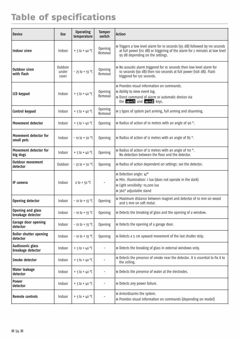
Table of specifications
� 54 �
Device Use Operatingtemperature
Tamperswitch Action
Indoor siren Indoor + 5 to + 40 °C OpeningRemoval
� Triggers a low level alarm for 10 seconds (95 dB) followed by 110 secondsat full power (112 dB) or triggering of the alarm for 2 minutes at low level95 dB depending on the settings.
Outdoor siren with flash
Outdoorundercover
- 25 to + 55 °C OpeningRemoval
� No acoustic alarm triggered for 10 seconds then low level alarm for10 seconds (90 dB) then 100 seconds at full power (108 dB). Flashtriggered for 120 seconds.
LCD keypad Indoor + 5 to + 40 °C OpeningRemoval
� Provides visual information on commands. � Ability to view event log. � Direct command of alarm or automatic devices via
the and keys.
Control keypad Indoor + 5 to + 40 °C OpeningRemoval
� 3 types of system part arming, full arming and disarming.
Movement detector Indoor + 5 to + 40 °C Opening � Radius of action of 10 metres with an angle of 90 °.
Movement detector forsmall pets Indoor - 10 to + 50 °C Opening � Radius of action of 12 metres with an angle of 85 °.
Movement detector forbig dogs Indoor + 5 to + 40 °C Opening � Radius of action of 12 metres with an angle of 110 °.
No detection between the floor and the detector.
Outdoor movementdetector Outdoor - 25 to + 50 °C Opening � Radius of action dependent on settings: see the detector.
IP camera Indoor 0 to + 50 °C -
� Detection angle: 47°� Min. illumination: 1 lux (does not operate in the dark)� Light sensitivity: 10,000 lux� 360° adjustable stand
Opening detector Indoor - 10 to + 55 °C Opening � Maximum distance between magnet and detector of 10 mm on woodand 5 mm on soft metal.
Opening and glassbreakage detector Indoor - 10 to + 55 °C Opening � Detects the breaking of glass and the opening of a window.
Garage door openingdetector Indoor - 10 to + 55 °C Opening � Detects the opening of a garage door.
Roller shutter openingdetector Indoor - 10 to + 55 °C Opening � Detects a 5 cm upward movement of the last shutter strip.
Audiosonic glass breakage detector Indoor + 5 to + 40 °C - � Detects the breaking of glass in external windows only.
Smoke detector Indoor + 5 to + 40 °C - � Detects the presence of smoke near the detector. It is essential to fix it tothe ceiling.
Water leakage detector Indoor + 5 to + 40 °C - � Detects the presence of water at the electrodes.
Power detector Indoor + 5 to + 40 °C - � Detects any power failure.
Remote controls Indoor + 5 to + 40 °C -� Arms/disarms the system.� Provides visual information on commands (depending on model)

Table of specifications
� 55 �
Device Operation Operatingtemperature
Tamperswitch Action
Central unit/phone dialer Indoor + 5 to + 40 °C OpeningRemoval
� Can only be used on an analogue line with DTMF code-compatibledialling for the PSTN module.
� Remote settings in voice mode via DTMF codes (requires a France Telecomline).
� Making local settings using the LCD keypad or by computer, depending onversion.
� Recording of a voice message to accompany the pre-recorded alarmmessage sent by PSTN from a remote telephone.
� Voice call by PSTN, SMS by GSM or digital transmission (for remotemonitoring) for alarms with the possibility of delaying these for up to 30 seconds (to prevent calls in the event of operator error).
� Possibility of sending SMS messages when the system is armed/disarmedon both access codes.. Remote full arming/disarming in voice mode bypressing “9” on the handset (DTMF codes).
PSTN module Indoor + 5 to + 40 °C - � Sending of synthesised voice alarm messages on the fixed line.
GSM module Indoor + 5 to + 40 °C - � Sending of alarm SMSs by GSM.
IndexArming............................................................................................8, 30 (menu 26), 46Automatic arming.....................................................................................................41Automatic devices ....................................................................................................39Batteries................................................................................................................50Beeps ..........................................................................................11, 20, 25, 37, 41, 46, 52Broadband ................................................................................................21, 23, 26, 33Customisation of devices ............................................................................................35Date .....................................................................................................................35Delayed triggering .....................................................................................................9Duress code, mute and Duress code + siren ................................................................30, 46Event log...........................................................................................................35, 49GSM (module) ......................................................................................5, 6, 21, 23, 24, 27Immediate triggering..................................................................................................9Installer code and user codes..............................................................................29, 30, 51Lighting ............................................................................................................40, 42Menu sequence diagram .......................................................................................29, 36Phone number ....................................................................................................31, 32Presence simulation with light.....................................................................................42Presence simulation with roller shutters .........................................................................43PSTN (module) ..................................................................................................5, 6, 22Radio range .............................................................................................................7Remote access ....................................................................................................45, 47Roller shutters ....................................................................................................40, 43SMS..................................................................................................................32, 33Storage of additional devices ...................................................................................11, 38Tamper switch.........................................................................................................50Time.....................................................................................................................35Welcome message ....................................................................................................45Zones (A, B, C) ..................................................................................................8, 9, 47
somfy.xx
MOTORISED ROLLER SHUTTERS
MOTORISED GARAGE DOORS
MOTORISED BLINDS
MOTORISED GATES LIGHTING WIRELESS RADIO ALARM SYSTEM
Due to our commitmen
t to the constant developmen
t and improvemen
t of our products, we reserve the right at all
times to make any modifications to them
which we consider to be of value. Photos and illustrations non-contractual.
SOMFY SAS, registered capital of 20,000,000 euros, Annecy Register of Companies 303.970.230
EM
NO 0
025
0-01
03/
2012
Customer service for professionals:
For all additional information:
www.somfy.xx