wireless networking spread spectrum technologies module-04 jerry bernardini community college of...
Post on 20-Dec-2015
225 views
TRANSCRIPT

Wireless Networking
Spread Spectrum TechnologiesModule-04
Jerry BernardiniCommunity College of Rhode Island
04/18/23 1Wireless Networking J. Bernardini

Presentation Reference Material
• CWNA Certified Wireless Network Administration Official Study Guide, Fourth Edition, Tom Carpenter, Joel Barrett
• Chapter-3
04/18/23 Wireless Networking J. Bernardini 2

OSI Model
04/18/23 Wireless Networking J. Bernardini 3

Telecommunication Channel
• Channel - a path along which information in the form of an electrical signal passes. Usually a range of contiguous frequencies involved in supporting information transmission.
Bandwidth
Amplitude
FrequencyChannel
CenterChannel Frequency

Narrow and Wide Band
• Narrow and Wide Band – a relative comparison of a group or range of frequencies used in a telecommunications system. Narrow Band would describe a small range of frequencies as compared to a larger Wide Band range.
Frequency
Amplitude
NB WB
Freq. RangefL fH
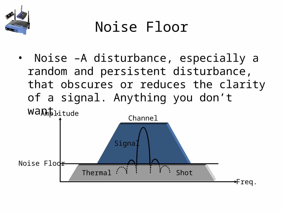
Noise Floor
• Noise –A disturbance, especially a random and persistent disturbance, that obscures or reduces the clarity of a signal. Anything you don’t want.
Channel
Noise FloorShot
Signal
Thermal
Amplitude
Freq.

Signal to Noise Ratio
Time
dBm.VRMS
Signal
Noise
100 V
10 V
-60 dBm
-95 dBm
SNRdB = 20 log (100 V/ 10 V) = 20 dB
SNRdB = -60 dBm – (-95 dBm) = 35 dB
SNR-1 SNR-2
SRX-91 dBm

Signal to Noise RatioOrinoco Client NetStumbler
AirMagnet
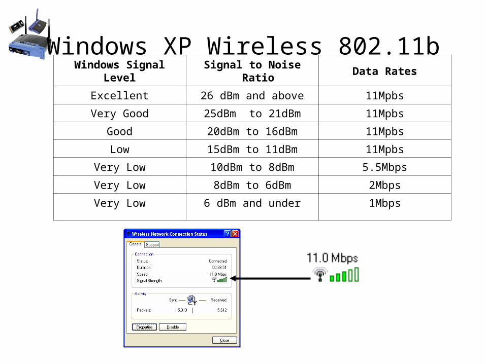
Windows XP Wireless 802.11bWindows Signal
LevelSignal to Noise Ratio Data Rates
Excellent 26 dBm and above 11Mpbs
Very Good 25dBm to 21dBm 11Mpbs
Good 20dBm to 16dBm 11Mpbs
Low 15dBm to 11dBm 11Mpbs
Very Low 10dBm to 8dBm 5.5Mbps
Very Low 8dBm to 6dBm 2Mbps
Very Low 6 dBm and under 1Mbps

Introduction to Spread Spectrum
• Spread Spectrum – a telecommunications technique in which a signal is transmitted in a bandwidth considerably greater than the frequency content of the original information.
Frequency
Amplitude Narrowband
Wideband

4-Types Spread Spectrum
• Time Hopping, (THSS)• Frequency Hopping, (FHSS)• Direct Sequence Spread Spectrum, (DSSS)• Hybrid, DSSS/FHSS

Uses of Spread Spectrum
• Military - For low probability of interception of telecommunications.
• Civil/Military - Range and positioning measurements. GPS – satellites.
• Civil Cellular Telephony.• Civil Wireless Networks – 802.11 and Bluetooth.

Frequency Hopping
• Hedy Lamarr and composer George Antheil, patent number 2,292,387circa 1942

FHSS
• FHSS - Acronym for frequency-hopping spread spectrum. 802.11, Bluetooth, & HomeRF.
Freq.
Amp.
1 2 3 4
Frequency Hop Sequence: 1, 3, 2, 4
Wide BandChannel
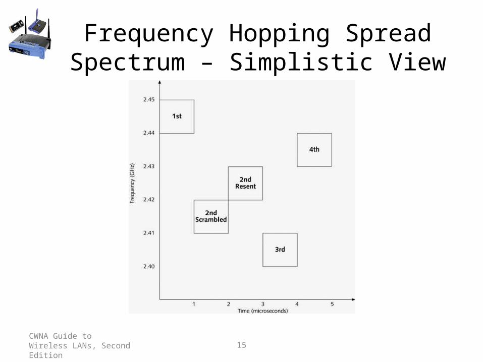
CWNA Guide to Wireless LANs, Second Edition 15
Frequency Hopping Spread Spectrum – Simplistic View

FHSS Timing
Frequency
Time
Amplitude
DwellTime
HopSequence
Channels
DataHopTime
12
34

FHSS System Block Diagram
Frequency Synthesizer
CarrierFrequency
DataBuffer
SequenceGenerator
MixerMod
AntennaFHSS
1 23 4
1 23 4
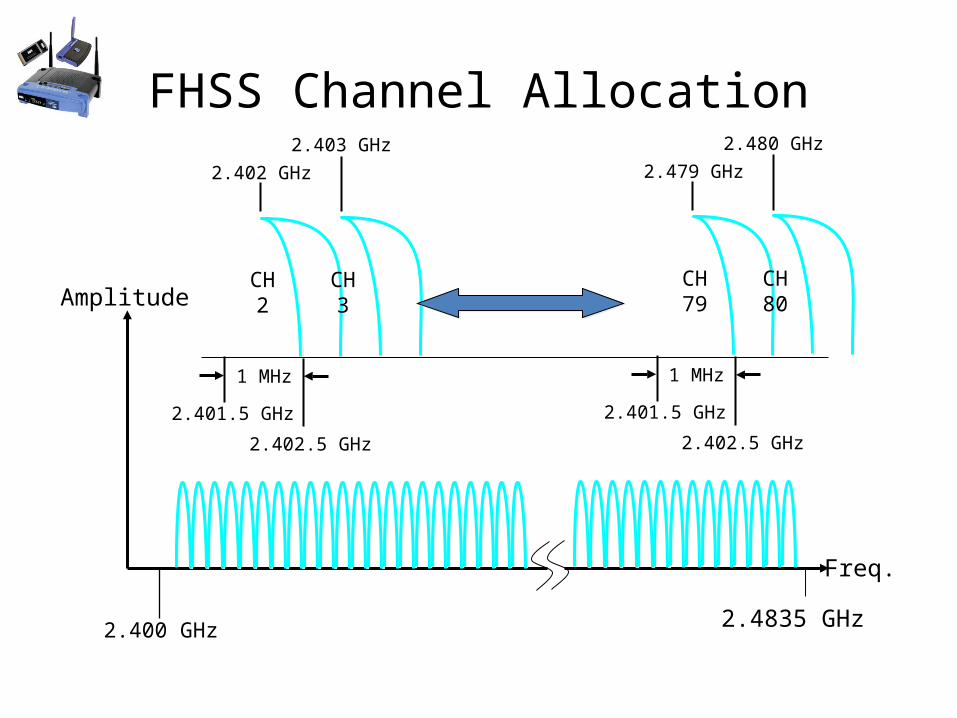
FHSS Channel Allocation
2.400 GHz 2.4835 GHz
Amplitude
Freq.
1 MHz
2.401.5 GHz
2.402.5 GHz
2.402 GHz
2.403 GHz
CH2
CH3
1 MHz
2.401.5 GHz
2.402.5 GHz
2.479 GHz
2.480 GHz
CH79
CH80

DSSS
• DSSS - Acronym for direct-sequence spread spectrum. WLAN, 802.11.
Freq.
Amp.
1 2 3 4
DSSS BandChannel
1 Signal
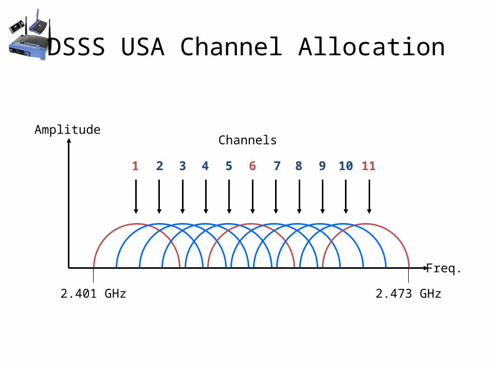
DSSS USA Channel Allocation
2.401 GHz 2.473 GHz
11 22 33 44 55 66 77 88 99 1010 1111
Amplitude
Freq.
Channels

DSSS 3 Non-overlap Channels
2.401 GHz 2.473 GHz
Ch 1 Ch 6 Ch 11(2.412 GHz) (2.437GHz) (2.462 GHz)
Amplitude
Freq.
2401 MHz
22 MHz
3MHz
2426 MHz
2423 MHz

DSSS System Block DiagramCarrier
Frequency
DataBuffer
Pseudo –Noise
Generator
Antenna
CarrierGenerator
11-bit Barker Code
Mixer
Encoder
DSSS
Chipping Code
Mod
10110111000
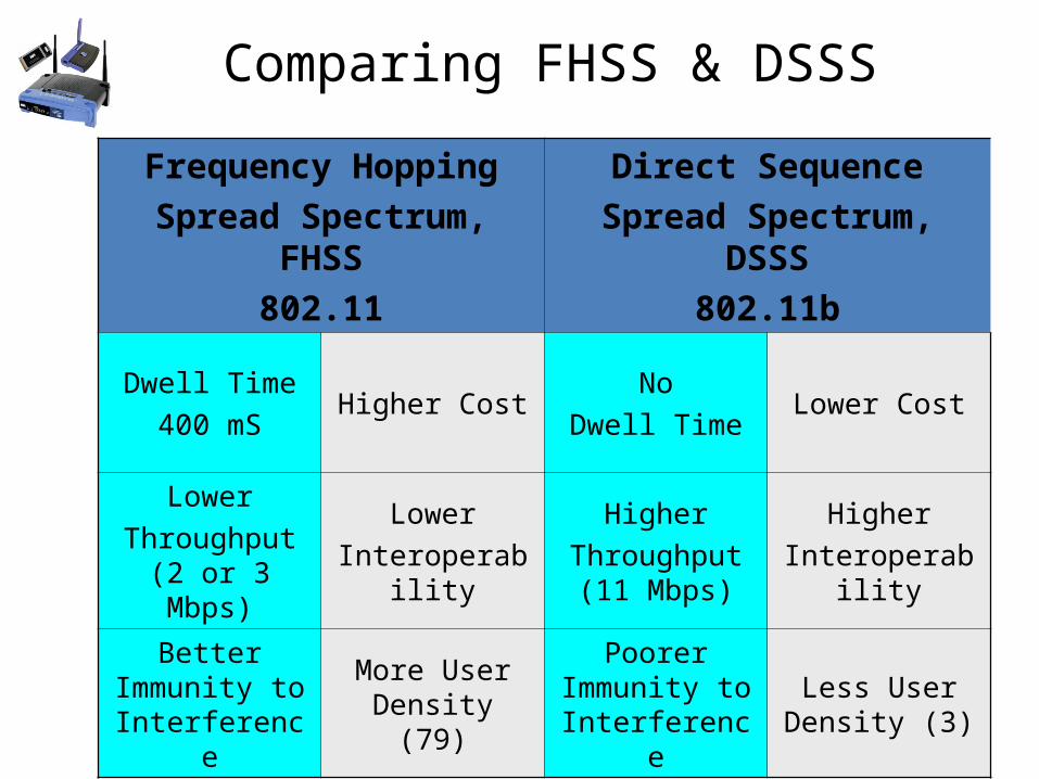
Comparing FHSS & DSSS
Frequency HoppingSpread Spectrum,
FHSS802.11
Direct SequenceSpread Spectrum,
DSSS802.11b
Dwell Time400 mS
Higher CostNo
Dwell TimeLower Cost
LowerThroughput
(2 or 3 Mbps)
LowerInteroperabili
ty
HigherThroughput (11 Mbps)
HigherInteroperabili
ty
Better Immunity to Interference
More User Density (79)
Poorer Immunity to Interference
Less User Density (3)
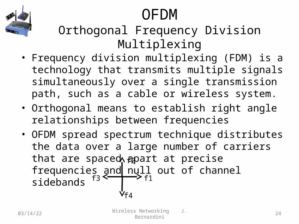
OFDMOrthogonal Frequency Division Multiplexing
• Frequency division multiplexing (FDM) is a technology that transmits multiple signals simultaneously over a single transmission path, such as a cable or wireless system.
• Orthogonal means to establish right angle relationships between frequencies
• OFDM spread spectrum technique distributes the data over a large number of carriers that are spaced apart at precise frequencies and null out of channel sidebands
04/18/23 Wireless Networking J. Bernardini 24
f1f3
f2
f4

IEEE 802.11nDraft Modulation
• Uses three modes of OFDM – 20MHz and 40 MHz bands– Data rates up to 600 Mbps
• Non-HT mode– OFDM– Backward compatibility to a, b, g
• HT mixed mode– Supports OFDM and ERP-OFDM
• Greenfield mode– Only ERP-OFDM– Highest data rates
04/18/23 Wireless Networking J. Bernardini 25

Encoding and Modulation
• Encoding - To change or translate one bit stream into another.Barker Code, Complementary Code Keying
• Modulation – Appling information on a carrier signal by varying one or more of the signal's basic characteristics - frequency, amplitude and phase.DBPSK (Differential Binary Phase Shift Keying) DQPSK (Differential Quaternary PSK)

Convolution Coding
• Convolution coding is a method of channel coding by adding additional redundant information to provide error correction. Convolution codes operate on serial data, one or a few bits at a time and may use Exclusive-Or logic and shift registers. This type of error correction is used in wireless OFDM schemes.

FCC Rules for FHSS
• Prior to 8-31-00– Use 75 of the 79 channels– Output Powermax = 1 Watt
– Bandwidthmax = 1 MHz
– Data Ratemax = 2 Mbps
• After 8-31-00– Only 15 of the 79 channels required– Output Powermax = 125 mW
– Bandwidthmax = 5 MHz
– Data Ratemax = 10 Mbps

Co-location
• Co-location is the ability to place multiple devices in a frequency space minimal interference
• FHSS has many more frequencies / channels then DSSS which only has 3 co-location channels.
• However 3 DSSS access points co-located at 11 Mbps each would result in a maximum throughput of 33 Mbps. It would require 16 access points co-located for FHSS to achieve a throughput of 32 Mbps.

Orinoco Gold 802.11bFrequency Channels 11, 2400 - 2483.5 MHz
Modulation Technique (DSSS) CCK,DQPSK, DBPSK
Encoding (Spreading) 11 - chip Barker Sequence
Nominal Output Power 15 dBm (31.6 mW)
11 Mbps 5.5 Mbps 2 Mbps 1 Mbps
25m (80ft) 35m (115 ft) 40m (130 ft) 50m (165 ft)
-82 dBm -86 dBm -91 dBm -94 dBm

Orinoco 802.11 abg
Frequency Channels
FCC (26 Channels) 2400-2484; 5150-5250; 5250-5350; 5725-5850 MHzETSI (32 Channels) 2400-2484; 5150-5250; 5250-5350; 5470-5720 MHzTELEC (18 Channels) 2400-2484; 5150-5250 MHzIDA (22 Channels) 2400-2484; 5150-5250; 5725-5850 MHz
Modulation Technique
802.11a, 802.11g Orthogonal Frequency Division Modulation (64 QAM, 16 QAM, QPSK, BPSK)802.11b Direct Sequence Spread Spectrum (CCK, DQPSK, DBPSK)
Data Speeds802.11a, 802.11g modes: 54, 48, 36, 24, 18, 12, 9, 6 Mbps802.11b mode: 11, 5.5, 2, 1 Mbps2X mode: 108, 96, 72, 48, 36, 24, 18, 12 Mbps
Max Output Power
802.11a, 802.11g: 60 mW EIRP802.11b: 85 mW EIRP

CWNA Guide to Wireless LANs, Second EditionCCRI J. Bernardini 32
Modulation
• Carrier signal is a continuous electrical signal– Carries no information
• Three types of modulations enable carrier signals to carry information– Height of signal– Frequency of signal– Relative starting point
• Modulation can be done on analog or digital transmissions
CWNA Guide to Wireless LANs, Second EditionCCRI J. Bernardini 33
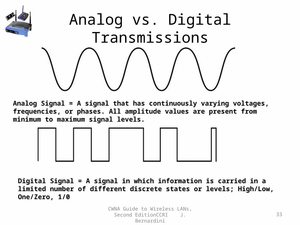
Analog vs. Digital Transmissions
Digital Signal = A signal in which information is carried in a limited number of different discrete states or levels; High/Low, One/Zero, 1/0
Analog Signal = A signal that has continuously varying voltages, frequencies, or phases. All amplitude values are present from minimum to maximum signal levels.

CWNA Guide to Wireless LANs, Second EditionCCRI J. Bernardini 34
Analog and Digital Modulation
• Analog Transmission use analog carrier signals and analog modulation.
• Digital Transmission use analog carrier signals and digital modulation.
• Modem (MOdulator/DEModulator): Used when digital signals must be transmitted over analog medium– On originating end, converts distinct digital signals into continuous analog
signal for transmission– On receiving end, reverse process performed
• WLANs use digital modulation of analog signals (carrier signal)

CWNA Guide to Wireless LANs, Second EditionCCRI J. Bernardini 35
Frequency and Period

CWNA Guide to Wireless LANs, Second EditionCCRI J. Bernardini 36
Analog Modulation
• Amplitude: Height of carrier wave• Amplitude modulation (AM): Changes amplitude so
that highest peaks of carrier wave represent 1 bit while lower waves represent 0 bit
• Frequency modulation (FM): Changes number of waves representing one cycle– Number of waves to represent 1 bit more than number of waves to
represent 0 bit
• Phase modulation (PM): Changes starting point of cycle– When bits change from 1 to 0 bit or vice versa

CWNA Guide to Wireless LANs, Second EditionCCRI J. Bernardini 37
Analog Modulation
Amplitude modulation (AM) – Carrier frequency varies in amplitude
Frequency modulation (FM) – Carrier frequency varies in frequency
Phase modulation (PM) – Carrier varies in phase

CWNA Guide to Wireless LANs, Second EditionCCRI J. Bernardini 38
Digital Modulation• Advantages over analog modulation:
– Better use of bandwidth– Requires less power– Better handling of interference from other signals– Error-correcting techniques more compatible with other digital
systems
• Unlike analog modulation, changes occur in discrete steps using binary signals– Uses same three basic types of modulation as analog
Amplitude shift keying (ASK)

CWNA Guide to Wireless LANs, Second EditionCCRI J. Bernardini 39
Digital Modulation
Frequency shift keying (FSK)
Phase shift keying (PSK)

CWNA Guide to Wireless LANs, Second Edition 40
Quadrature phase shift keying (QPSK)

CWNA Guide to Wireless LANs, Second Edition 41
Physical Layer Standards (continued)
Figure 4-21: 16-level quadrature amplitude modulation (16-QAM)

CWNA Guide to Wireless LANs, Second Edition 42
Physical Layer Standards (continued)
Figure 4-22: 64-level quadrature amplitude modulation (64-QAM)

Summary PHY Data Rates Frequency
BandStandards Max Colocated
WLANsMax Total
Service Area Data Rate
FHSS 1 or 2 Mbps 2.4 GHz ISM IEEE 802.11 1997
79 max,12 practical
24 Mbpspractical
DSSS 1 or 2 Mbps 2.4 GHz ISM IEEE 802.11 1997
2 or 3 6 Mbps
HR/DSSS
1, 2, 5.5, or11 Mbps
2.4 GHz ISM IEEE802.11b1999
3 33 Mbps
ERP 1-54 Mbps 2.4 GHz ISM IEEE 802.11g 2003
3 162 Mbps
OFDM 6-54 Mbps 5 GHz U-NII IEEE 802.11a 1999
23 648 Mbps
04/18/23 Wireless Networking J. Bernardini 43

Throughput vs. Data Rate
• Data Rate = Total Data Rate through system• Throughput = Data Payload Rate• Data Rate = Data Payload Rate + Overhead• Overhead = Coding + Modulation+ Bandwidth +
Hardware + Software + Retransmission(errors)
04/18/23 Wireless Networking J. Bernardini 44
5 Mbps Throughput 11 Mbps Data Rate 5 Mbps Throughput
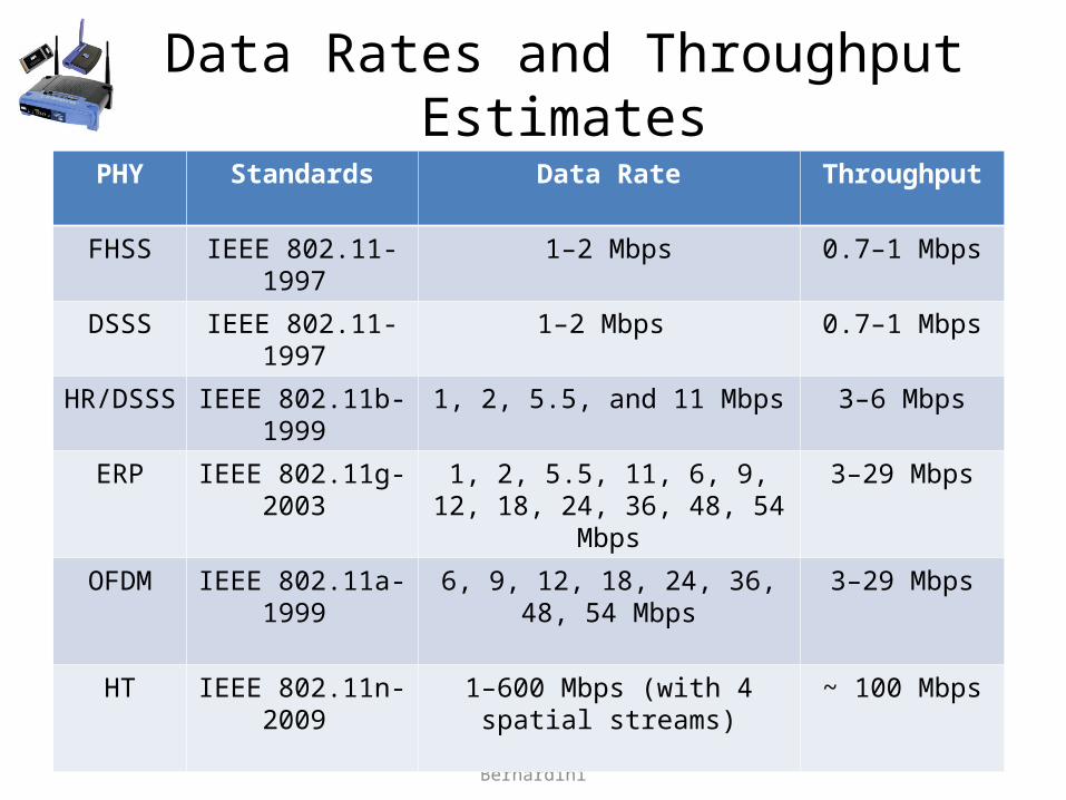
Data Rates and Throughput Estimates
04/18/23 Wireless Networking J. Bernardini 45
PHY Standards Data Rate Throughput
FHSS IEEE 802.11-1997 1–2 Mbps 0.7–1 Mbps
DSSS IEEE 802.11-1997 1–2 Mbps 0.7–1 Mbps
HR/DSSS IEEE 802.11b-1999 1, 2, 5.5, and 11 Mbps 3–6 Mbps
ERP IEEE 802.11g-2003 1, 2, 5.5, 11, 6, 9, 12, 18, 24, 36, 48, 54 Mbps
3–29 Mbps
OFDM IEEE 802.11a-1999 6, 9, 12, 18, 24, 36, 48, 54 Mbps 3–29 Mbps
HT IEEE 802.11n-2009 1–600 Mbps (with 4 spatial streams)
~ 100 Mbps

Bandwidths• Analog Bandwidth – Frequency in Khz,Mhz (1 Mhz)• Digital Bandwidth – bits per second (11 Mbps)• Wireless Bandwidth – Frequency Space made
available to network devices (22 Mhz)
04/18/23 Wireless Networking J. Bernardini 46
Frequency
Amplitude
BandwidthDigital Bandwidth (Average Bit Rate)

Communication Resilience
• Resistance to interference• FHSS best resilience but lowest throughput• OFDM next best resilience and higher throughput• HT-OFDM in IEEE 802.11n will provide the best
resilience and the best throughput
04/18/23 Wireless Networking J. Bernardini 47

Key Terms and Concepts• bandwidth• coding• colocation• data rate• DSSS• ERP• FHSS• HR/DSSS• modulation• OFDM• throughput
04/18/23 Wireless Networking J. Bernardini 48