wireless modem exchange (wmx) protocol description
TRANSCRIPT
Company Confidential 1 Raveon Technologies Corp.
Wireless Modem Exchange (WMX)
Protocol Description Document Version D4
July 2013
Raveon Technologies Corporation 2461 Impala Drive
Carlsbad, CA 92010 www.raveon.com
Company Confidential 2 Raveon Technologies Corp.
Table of Contents
1. WMX Revision Log.........................................................................................3
2. WMX Overview ..............................................................................................3 2.1. What is WMX? ............................................................................................................................... 3 2.2. Protocol Features .......................................................................................................................... 3 2.3. Why another Protocol? .................................................................................................................. 4 2.4. WMX Protocol Stack ...................................................................................................................... 4 2.5. WMX Frames ................................................................................................................................. 4 2.6. Enabling WMX ............................................................................................................................... 5
3. Frame Format ................................................................................................6 3.1. WMX Frame Format ...................................................................................................................... 6
*1 Control Field........................................................................................................................................ 7
3.2. WMX Control Byte List ................................................................................................................... 7 3.3. Command Request Field Format .................................................................................................. 8 3.4. Checksum ...................................................................................................................................... 8 3.5. RSSI Field ...................................................................................................................................... 8
4. WMX Messaging ............................................................................................9 4.1. Sending Data Bytes ....................................................................................................................... 9 4.2. Sending Raw Binary Data ............................................................................................................ 10 4.3. Binary Encoding ........................................................................................................................... 11 4.4. Receiving Data ............................................................................................................................ 11 4.5. Binary Decoding .......................................................................................................................... 13 4.6. Issuing Commands ...................................................................................................................... 14 4.7. Receiving Responses .................................................................................................................. 15 4.8. Modem Status Responses ........................................................................................................... 16
Modem Status Data Field .................................................................................................................... 17
5. WMX Parsing Conventions .......................................................................... 18
Company Confidential 3 Raveon Technologies Corp.
1. WMX Revision Log
Version Date Changes
C0 Dec 3, 2009 Added RSSI field
C1 Jan, 2011 Added explanation of data encoding method
D1 Jan, 2013 Added Raw Bit transfer packet format
D2 Apr, 2013 Corrected errors involving field separator 2
D4 July, 2013 Added draft of WMX status ACKs
2. WMX Overview
2.1. What is WMX?
WMX is the communication protocol used in Raveon’s wireless modems, to allow a user to have full control over these sending and receiving of data. It enables the user of a Raveon modem to specify the destination ID when sending data. It also allows the user to identify the source of data when data is received.
Without the WMX protocol, a Raveon wireless modem transparently sends and receives data to and from other Raveon modems, and the ID of the modems in the network are all pre-configured at time of installation.
With WMX, the user my specify “on-the-fly” the destination ID of data that is to be transmitted. All received data is passed to the user in a pre-defined format, so the source of the data may be determined.
Also, the WMX protocol allows for sending “Commands” to other radio modems. This allows the user to execute certain functions or control certain features of another remote modem – using the WMX Command protocol.
To enable the WMX protocol on the M7 series of radios, issue the WMX 1 command. WMX 0 disables it.
2.2. Protocol Features
The WMX protocol was developed at Raveon Technologies Corporation with the following goals.
1. Provide an easy-to-use interface to a wireless point-to-multipoint network.
2. Add addressing capability to serial protocols and messages that do not have addressing.
3. Simplify user’s software development tasks.
4. Allow the protocol to be implemented on 8-bit microcontrollers with limited resources.
5. Provision for addressing of transmissions by ID or group.
6. Provide secure access to internal modem configuration settings.

Company Confidential 4 Raveon Technologies Corp.
7. Provision for unacknowledged data transmission
8. Provision for acknowledged data transmission with delivery verification (tbt)
9. Enable remote control of certain product features such as digital I/O and GPS tracking.
2.3. Why another Protocol?
Raveon’s wireless modems have a very sophisticated over-the-air protocol that is hidden from the user’s application. Raveon’s modems “transparently” send and receive data, and technical issues such as addressing, re-transmission, and error-detection are handled internal to the Raveon wireless modem.
But customers were asking for external access to some of these features. They wanted to be able to easily address a data transmission, know if it was delivered, control a feature, or read a diagnostic message.
An extensive review of industry standard protocols revealed that internet protocols were too cumbersome to use on narrow-band data links. They are also complex to implement in customer’s simple microcontrollers. Older data-link protocols such as X.25 or HDLC required specialized hardware to implement, and again, for the simple micro-controller, the software overhead required was excessive.
WMX is easy to implement. In some cases, it could be added to an existing design with only a few hours of software work. It provides a powerful interface to the wireless modem and the radio channel. A full implementation includes over 50 commands and features, but it also may be minimally implemented by only two simple messages – Send Data and Receive data.
2.4. WMX Protocol Stack
The WMX protocol is the serial communications protocol used to communicate with a Raveon radio modem. Currently both the M7 radio modem, M7 GX GPS transponder, and the the ATLAS line of personal locators support WMX, as long as they have firmware version B11 or higher.
WMX is not an “over-the-air” protocol. It is a communication protocol that interfaces between the user’s application and the Raveon radio modem. Effectively, it is a serial communication protocol. WMX message frames pass into the modem, and are converted to standard data transmissions, with the proper ID settings. A WMX enabled modem that receives data over the air, will format the data into the WMX receive data frame format before sending it out the serial port.
2.5. WMX Frames
There are two fundamental uses for the WMX protocol; to transfer data, and to send commands.
Data Exchange WMX Data frames are used pass data bytes into a modem, so that the modem may send the data over the radio link. The data may be any ASCII or binary data the user wishes to
Company Confidential 5 Raveon Technologies Corp.
send to a radio modem. Data sent into a modem using the WMX protocol is sent over-the-air in the same format as if it had been sent into the modem’s serial port. The only difference is that the WMX user was able to specify the destination ID that the data was to be sent to.
Commands The WMX Command frame is used to pass a command from an external device, to a local or remote radio modem. If the command was for the local modem, then it is executed by the local modem and the results returned back through to originating port. If the command is not for the local modem (Based on the ID), then the command is transmitted over-the-air, for processing by another radio modem in the system. Over-the-air commands are passed using Remote Procedure Requests (RPR). RPR is standard in all Raveon wireless modems, and the WMX protocol gives the user easy access to sending RPRs to any modem ID. Without WMX, the user would have cause the local modem to enter the command mode, manually enter the RPR command, and then wait for a response.
2.6. Enabling WMX
On products that support WMX, there is a WMX command. WMX 1 enables the protocol, and WMX 0 disables it.
Company Confidential 6 Raveon Technologies Corp.
3. Frame Format
3.1. WMX Frame Format
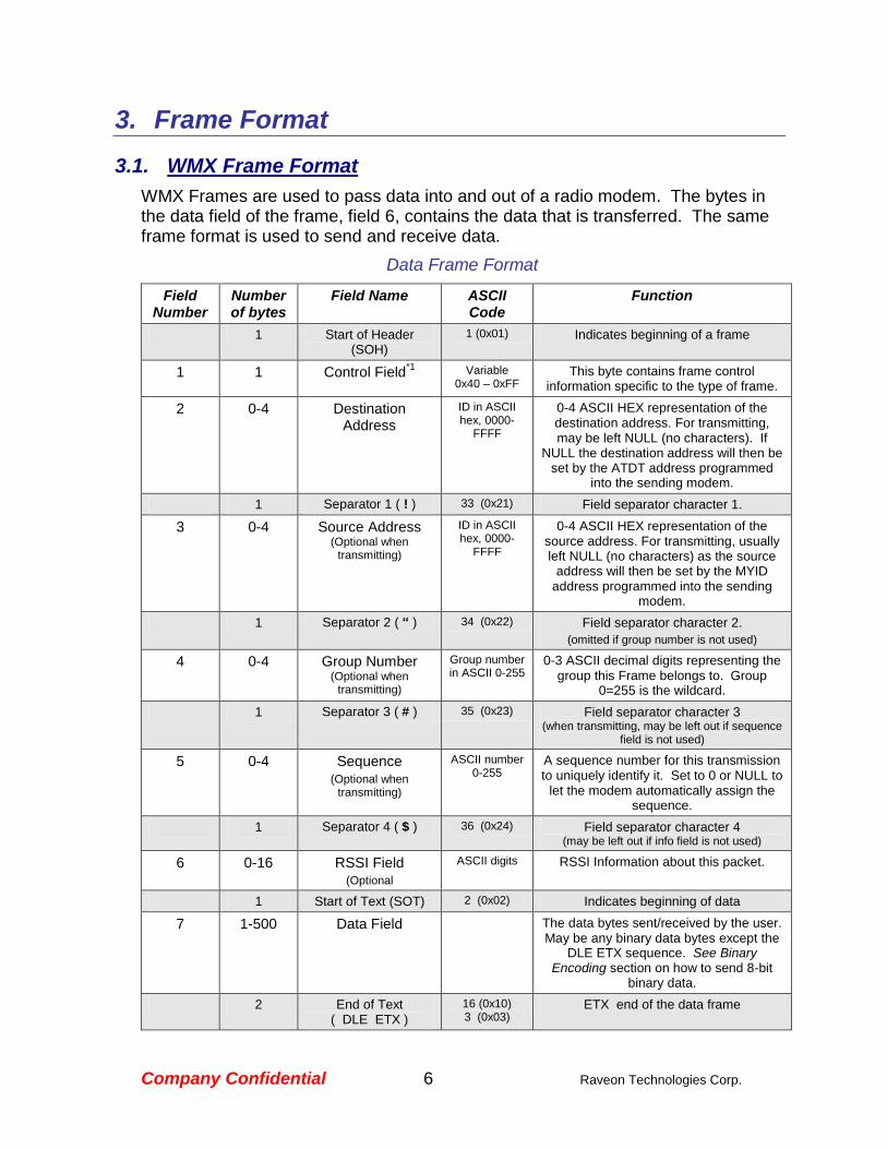
WMX Frames are used to pass data into and out of a radio modem. The bytes in the data field of the frame, field 6, contains the data that is transferred. The same frame format is used to send and receive data.
Data Frame Format
Field Number
Number of bytes
Field Name ASCII Code
Function
1 Start of Header (SOH)
1 (0x01) Indicates beginning of a frame
1 1 Control Field*1
Variable 0x40 – 0xFF
This byte contains frame control information specific to the type of frame.
2 0-4 Destination Address
ID in ASCII hex, 0000-
FFFF
0-4 ASCII HEX representation of the destination address. For transmitting, may be left NULL (no characters). If
NULL the destination address will then be set by the ATDT address programmed
into the sending modem.
1 Separator 1 ( ! ) 33 (0x21) Field separator character 1.
3 0-4 Source Address (Optional when
transmitting)
ID in ASCII hex, 0000-
FFFF
0-4 ASCII HEX representation of the source address. For transmitting, usually left NULL (no characters) as the source
address will then be set by the MYID address programmed into the sending
modem.
1 Separator 2 ( “ ) 34 (0x22) Field separator character 2.
(omitted if group number is not used)
4 0-4 Group Number (Optional when
transmitting)
Group number in ASCII 0-255
0-3 ASCII decimal digits representing the group this Frame belongs to. Group
0=255 is the wildcard.
1 Separator 3 ( # ) 35 (0x23) Field separator character 3 (when transmitting, may be left out if sequence
field is not used)
5 0-4 Sequence (Optional when
transmitting)
ASCII number 0-255
A sequence number for this transmission to uniquely identify it. Set to 0 or NULL to
let the modem automatically assign the sequence.
1 Separator 4 ( $ ) 36 (0x24) Field separator character 4 (may be left out if info field is not used)
6 0-16 RSSI Field (Optional
ASCII digits RSSI Information about this packet.
1 Start of Text (SOT) 2 (0x02) Indicates beginning of data
7 1-500 Data Field The data bytes sent/received by the user. May be any binary data bytes except the
DLE ETX sequence. See Binary Encoding section on how to send 8-bit
binary data.
2 End of Text ( DLE ETX )
16 (0x10) 3 (0x03)
ETX end of the data frame

Company Confidential 7 Raveon Technologies Corp.
8 0 - 4 ASCII hex Checksum (Optional)
Variable 0-FFFF
The 16-bit checksum of all the previous bytes, starting with the SOH through the
end of the data bytes, not including DLE/ETX. Most significant digit first.
1 End of Transmission (EOT)
4 (0x04) Indicates end of the frame
*1 Control Field
The Control Field is used to identify the type of frame, and manage certain options.
Bit Num
7 6 5 4 3 2 1 0
Usage Reserved Always1
MODEM STAT REQ
OTA ACK Requested
Frame Type
Value (Set to 0
if reserved)
0 1 0 = no 1 = yes
0 = no 1 = yes
0 = Transmit Data Bytes
1 = Reserved for OEM use 2 = Received Data 3 = ACK received
4 = Command Request 5 = Command Response
6 = Transmit Raw Bits
7 = MODEM Status
The lower 4 bits of the Control Filed identify the type of WMX frame being passed.
Bit 4 is used to specify if the user wishes the receiving modem to send an acknowledgement that the message was received. If bit 4 is 0, not AKC is requested. If it is 1, the receiving modem will automatically send a special ACK message back over-the-air to let the sending station know it received the message.
Bit 5, MODEM STAT REQ, tells the MODEM that it must return two WMX “MODEM Status” frames
back message to the originator. The two messages are returned when:
A) Receives this WMX message. All WMX devices will return a WMX MODEM status.
B) Processes this WMX message completely. For transmitters, it will send a MODEM Status indicating TX success once the complete transmission has been sent.
Currently, products supporting the WMX protocol have frame buffers capable of handling WMX frames with up to 256 bytes of data.
3.2. WMX Control Byte List
0x40 Send Data, no ACK required (Use for normal WMX data communications
between modems)
0x50 Send Data, ACK (Future Version)
0x42 Receive Data (Normal WMX message when a radio receives data over-the-air)
0x44 Send a command, no ACK required
Company Confidential 8 Raveon Technologies Corp.
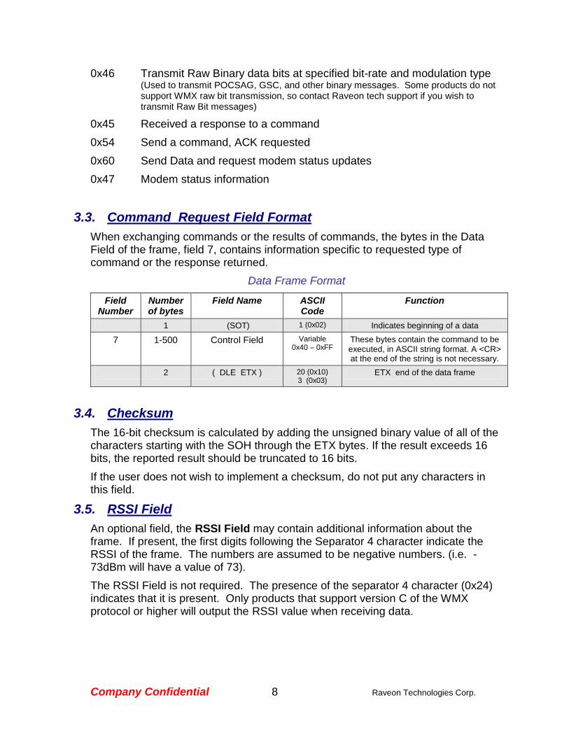
0x46 Transmit Raw Binary data bits at specified bit-rate and modulation type (Used to transmit POCSAG, GSC, and other binary messages. Some products do not support WMX raw bit transmission, so contact Raveon tech support if you wish to transmit Raw Bit messages)
0x45 Received a response to a command
0x54 Send a command, ACK requested
0x60 Send Data and request modem status updates
0x47 Modem status information
3.3. Command Request Field Format
When exchanging commands or the results of commands, the bytes in the Data Field of the frame, field 7, contains information specific to requested type of command or the response returned.
Data Frame Format
Field Number
Number of bytes
Field Name ASCII Code
Function
1 (SOT) 1 (0x02) Indicates beginning of a data
7 1-500 Control Field Variable 0x40 – 0xFF
These bytes contain the command to be executed, in ASCII string format. A <CR> at the end of the string is not necessary.
2 ( DLE ETX ) 20 (0x10) 3 (0x03)
ETX end of the data frame
3.4. Checksum
The 16-bit checksum is calculated by adding the unsigned binary value of all of the characters starting with the SOH through the ETX bytes. If the result exceeds 16 bits, the reported result should be truncated to 16 bits.
If the user does not wish to implement a checksum, do not put any characters in this field.
3.5. RSSI Field
An optional field, the RSSI Field may contain additional information about the frame. If present, the first digits following the Separator 4 character indicate the RSSI of the frame. The numbers are assumed to be negative numbers. (i.e. -73dBm will have a value of 73).
The RSSI Field is not required. The presence of the separator 4 character (0x24) indicates that it is present. Only products that support version C of the WMX protocol or higher will output the RSSI value when receiving data.
Company Confidential 9 Raveon Technologies Corp.
4. WMX Messaging
4.1. Sending Data Bytes
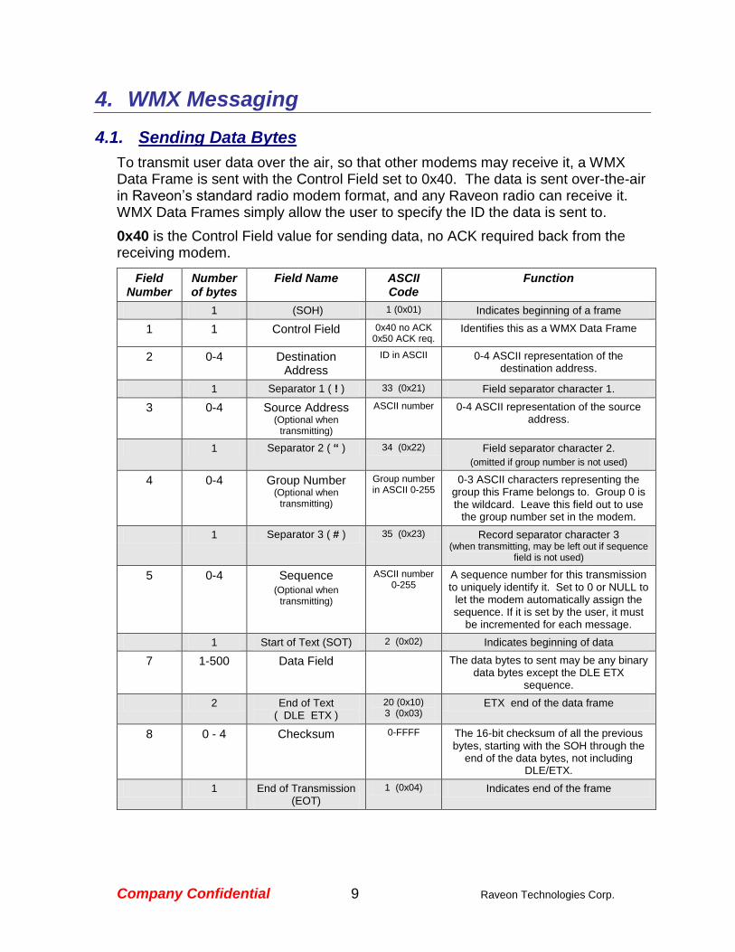
To transmit user data over the air, so that other modems may receive it, a WMX Data Frame is sent with the Control Field set to 0x40. The data is sent over-the-air in Raveon’s standard radio modem format, and any Raveon radio can receive it. WMX Data Frames simply allow the user to specify the ID the data is sent to.
0x40 is the Control Field value for sending data, no ACK required back from the receiving modem.
Field Number
Number of bytes
Field Name ASCII Code
Function
1 (SOH) 1 (0x01) Indicates beginning of a frame
1 1 Control Field 0x40 no ACK 0x50 ACK req.
Identifies this as a WMX Data Frame
2 0-4 Destination Address
ID in ASCII 0-4 ASCII representation of the destination address.
1 Separator 1 ( ! ) 33 (0x21) Field separator character 1.
3 0-4 Source Address (Optional when
transmitting)
ASCII number 0-4 ASCII representation of the source address.
1 Separator 2 ( “ ) 34 (0x22) Field separator character 2.
(omitted if group number is not used)
4 0-4 Group Number (Optional when
transmitting)
Group number in ASCII 0-255
0-3 ASCII characters representing the group this Frame belongs to. Group 0 is the wildcard. Leave this field out to use
the group number set in the modem.
1 Separator 3 ( # ) 35 (0x23) Record separator character 3 (when transmitting, may be left out if sequence
field is not used)
5 0-4 Sequence (Optional when
transmitting)
ASCII number 0-255
A sequence number for this transmission to uniquely identify it. Set to 0 or NULL to
let the modem automatically assign the sequence. If it is set by the user, it must
be incremented for each message.
1 Start of Text (SOT) 2 (0x02) Indicates beginning of data
7 1-500 Data Field The data bytes to sent may be any binary data bytes except the DLE ETX
sequence.
2 End of Text ( DLE ETX )
20 (0x10) 3 (0x03)
ETX end of the data frame
8 0 - 4 Checksum 0-FFFF The 16-bit checksum of all the previous bytes, starting with the SOH through the
end of the data bytes, not including DLE/ETX.
1 End of Transmission (EOT)
1 (0x04) Indicates end of the frame
Company Confidential 10 Raveon Technologies Corp.
When a WMX capable modem receives a frame in the above format, it parses out the IDs and then sends the Data Field over the air, with a destination address as specified in field 2.
The sequence number is optional, but if the user specifies it in the WMX Frame, then each transmission to an individual ID should have a new sequence number. If the receiving modem also uses WMX, then the user at the receiving modem will also receive the sequence number as specified by the sending modem.
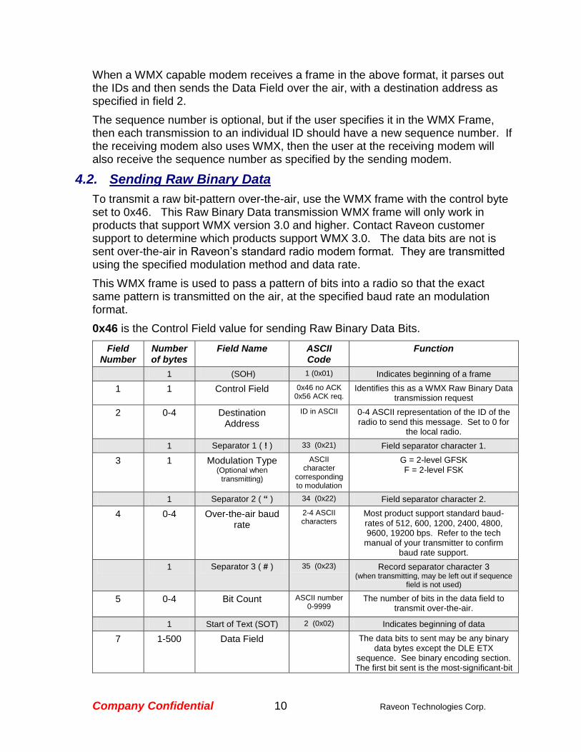
4.2. Sending Raw Binary Data
To transmit a raw bit-pattern over-the-air, use the WMX frame with the control byte set to 0x46. This Raw Binary Data transmission WMX frame will only work in products that support WMX version 3.0 and higher. Contact Raveon customer support to determine which products support WMX 3.0. The data bits are not is sent over-the-air in Raveon’s standard radio modem format. They are transmitted using the specified modulation method and data rate.
This WMX frame is used to pass a pattern of bits into a radio so that the exact same pattern is transmitted on the air, at the specified baud rate an modulation format.
0x46 is the Control Field value for sending Raw Binary Data Bits.
Field Number
Number of bytes
Field Name ASCII Code
Function
1 (SOH) 1 (0x01) Indicates beginning of a frame
1 1 Control Field 0x46 no ACK 0x56 ACK req.
Identifies this as a WMX Raw Binary Data transmission request
2 0-4 Destination Address
ID in ASCII 0-4 ASCII representation of the ID of the radio to send this message. Set to 0 for
the local radio.
1 Separator 1 ( ! ) 33 (0x21) Field separator character 1.
3 1 Modulation Type (Optional when
transmitting)
ASCII character
corresponding to modulation
G = 2-level GFSK F = 2-level FSK
1 Separator 2 ( “ ) 34 (0x22) Field separator character 2.
4 0-4 Over-the-air baud rate
2-4 ASCII characters
Most product support standard baud-rates of 512, 600, 1200, 2400, 4800, 9600, 19200 bps. Refer to the tech
manual of your transmitter to confirm baud rate support.
1 Separator 3 ( # ) 35 (0x23) Record separator character 3 (when transmitting, may be left out if sequence
field is not used)
5 0-4 Bit Count
ASCII number 0-9999
The number of bits in the data field to transmit over-the-air.
1 Start of Text (SOT) 2 (0x02) Indicates beginning of data
7 1-500 Data Field The data bits to sent may be any binary data bytes except the DLE ETX
sequence. See binary encoding section. The first bit sent is the most-significant-bit

Company Confidential 11 Raveon Technologies Corp.
of the first byte.
2 End of Text ( DLE ETX )
20 (0x10) 3 (0x03)
ETX end of the data frame
8 0 - 4 Checksum 0-FFFF The 16-bit checksum of all the previous bytes, starting with the SOH through the
end of the data bytes, not including DLE/ETX.
1 End of Transmission (EOT)
1 (0x04) Indicates end of the frame
When a WMX capable modem receives a frame in the above format, it parses out the bits from the Data Field, sets the baud rate and modulation type as specified, keys the transmitter, and sends the specified number of bits over the air. A digital 1 is positive deviation, and a digital 0 is negative deviation.
4.3. Binary Encoding
The Data Field of the WMX frame holds the data to be transmitted over the air. For any application that sends standard ASCII characters, no special formatting is required.
When sending binary data, there is a chance that the special WMX control characters may appear within the binary data. To ensure the control characters are not in the binary data, a byte-substitution technique is used. The data that is in the Data Field must not contain the special control codes 0x03 (ETX), or 0x04(EOT). IF the user wishes to send these characters, they must be replaced per the table below. The radio modem will restore them when they are transmitted over the air, so that the receiving station receives the correct binary data, including 0x03 and 0x04 characters.
Byte to Transmit Bytes to replace it with
0xFF 0xFF 0x00
0x03 0xFF 0xFC
0x04 0xFF 0xFB
0x0D 0xFF 0xF2
For example, to send the following 3 bytes: 0x10 0x04 0x30 the user would load the Data Field of the WMX frame with 0x10 0xFF 0xFB 0x30.
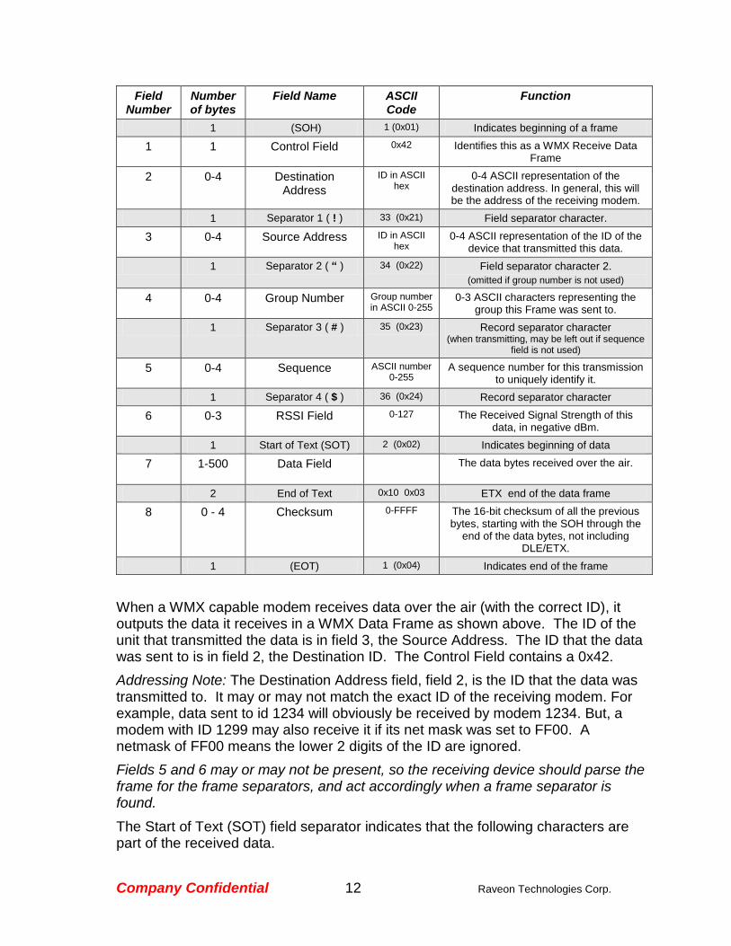
4.4. Receiving Data
When a WMX capable modem receives over-the-air data, it outputs a WMX frame with the Control Field containing an ASCII 0x42 (and ASCII “B”).
Company Confidential 12 Raveon Technologies Corp.
Field Number
Number of bytes
Field Name ASCII Code
Function
1 (SOH) 1 (0x01) Indicates beginning of a frame
1 1 Control Field 0x42 Identifies this as a WMX Receive Data Frame
2 0-4 Destination Address
ID in ASCII hex
0-4 ASCII representation of the destination address. In general, this will be the address of the receiving modem.
1 Separator 1 ( ! ) 33 (0x21) Field separator character.
3 0-4 Source Address ID in ASCII hex
0-4 ASCII representation of the ID of the device that transmitted this data.
1 Separator 2 ( “ ) 34 (0x22) Field separator character 2.
(omitted if group number is not used)
4 0-4 Group Number Group number in ASCII 0-255
0-3 ASCII characters representing the group this Frame was sent to.
1 Separator 3 ( # ) 35 (0x23) Record separator character (when transmitting, may be left out if sequence
field is not used)
5 0-4 Sequence ASCII number 0-255
A sequence number for this transmission to uniquely identify it.
1 Separator 4 ( $ ) 36 (0x24) Record separator character
6 0-3 RSSI Field 0-127 The Received Signal Strength of this data, in negative dBm.
1 Start of Text (SOT) 2 (0x02) Indicates beginning of data
7 1-500 Data Field The data bytes received over the air.
2 End of Text 0x10 0x03 ETX end of the data frame
8 0 - 4 Checksum 0-FFFF The 16-bit checksum of all the previous bytes, starting with the SOH through the
end of the data bytes, not including DLE/ETX.
1 (EOT) 1 (0x04) Indicates end of the frame
When a WMX capable modem receives data over the air (with the correct ID), it outputs the data it receives in a WMX Data Frame as shown above. The ID of the unit that transmitted the data is in field 3, the Source Address. The ID that the data was sent to is in field 2, the Destination ID. The Control Field contains a 0x42.
Addressing Note: The Destination Address field, field 2, is the ID that the data was transmitted to. It may or may not match the exact ID of the receiving modem. For example, data sent to id 1234 will obviously be received by modem 1234. But, a modem with ID 1299 may also receive it if its net mask was set to FF00. A netmask of FF00 means the lower 2 digits of the ID are ignored.
Fields 5 and 6 may or may not be present, so the receiving device should parse the frame for the frame separators, and act accordingly when a frame separator is found.
The Start of Text (SOT) field separator indicates that the following characters are part of the received data.

Company Confidential 13 Raveon Technologies Corp.
The received data is embedded in field 7, the Data Field of the WMX frame.
4.5. Binary Decoding
The Data Field of the WMX frame holds the data received over the air. For any application that sends/receives standard ASCII characters, no special formatting is required.
When receiving binary data, there is a chance that the special WMX control characters were transmitted. To ensure the control characters are not in the binary data, a byte-substitution technique is used.
The 0xFF character is used to identify special binary data values. The hex number 0xFF is decimal 255. Whenever a 0xFF is in the Data Frame, the following byte indicates the actual desired binary data that should be received.
Actual Byte Bytes Received
0xFF 0xFF 0x00
0x03 0xFF 0xFC
0x04 0xFF 0xFB
For example, if the Data Field contains the following 4 bytes: 0x10 0xFF 0xFB 0x30 the user must convert them to the actual binary data of 0x10 0x04 0x30 by replacing the 0xFF 0xFB sequence with 0x04.
Company Confidential 14 Raveon Technologies Corp.
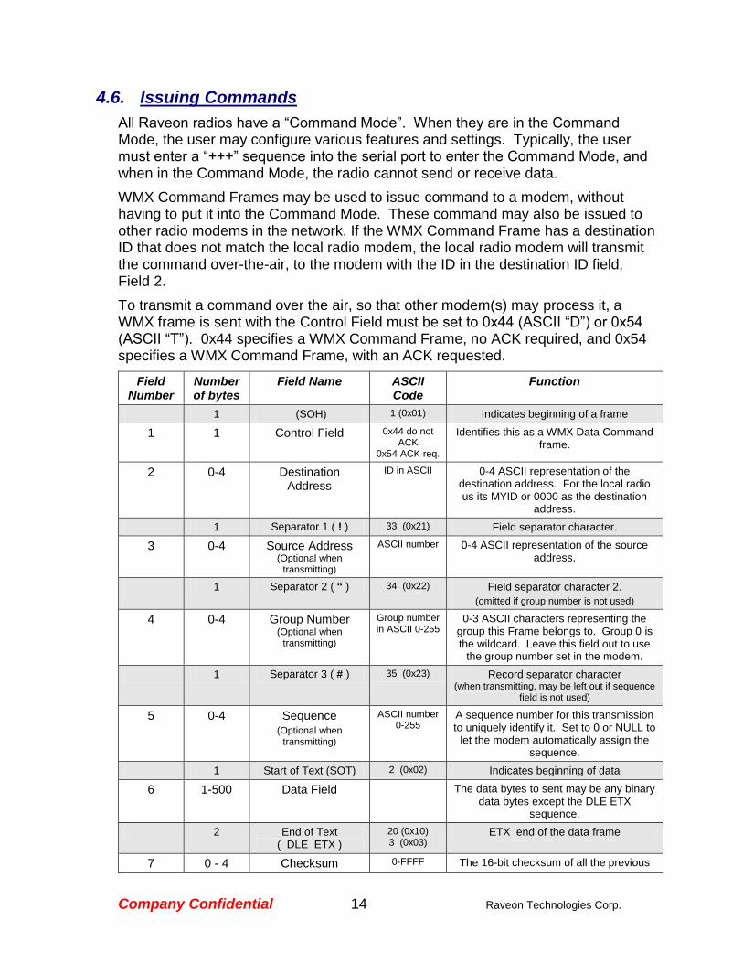
4.6. Issuing Commands
All Raveon radios have a “Command Mode”. When they are in the Command Mode, the user may configure various features and settings. Typically, the user must enter a “+++” sequence into the serial port to enter the Command Mode, and when in the Command Mode, the radio cannot send or receive data.
WMX Command Frames may be used to issue command to a modem, without having to put it into the Command Mode. These command may also be issued to other radio modems in the network. If the WMX Command Frame has a destination ID that does not match the local radio modem, the local radio modem will transmit the command over-the-air, to the modem with the ID in the destination ID field, Field 2.
To transmit a command over the air, so that other modem(s) may process it, a WMX frame is sent with the Control Field must be set to 0x44 (ASCII “D”) or 0x54 (ASCII “T”). 0x44 specifies a WMX Command Frame, no ACK required, and 0x54 specifies a WMX Command Frame, with an ACK requested.
Field Number
Number of bytes
Field Name ASCII Code
Function
1 (SOH) 1 (0x01) Indicates beginning of a frame
1 1 Control Field 0x44 do not ACK
0x54 ACK req.
Identifies this as a WMX Data Command frame.
2 0-4 Destination Address
ID in ASCII 0-4 ASCII representation of the destination address. For the local radio us its MYID or 0000 as the destination
address.
1 Separator 1 ( ! ) 33 (0x21) Field separator character.
3 0-4 Source Address (Optional when
transmitting)
ASCII number 0-4 ASCII representation of the source address.
1 Separator 2 ( “ ) 34 (0x22) Field separator character 2.
(omitted if group number is not used)
4 0-4 Group Number (Optional when
transmitting)
Group number in ASCII 0-255
0-3 ASCII characters representing the group this Frame belongs to. Group 0 is the wildcard. Leave this field out to use
the group number set in the modem.
1 Separator 3 ( # ) 35 (0x23) Record separator character (when transmitting, may be left out if sequence
field is not used)
5 0-4 Sequence (Optional when
transmitting)
ASCII number 0-255
A sequence number for this transmission to uniquely identify it. Set to 0 or NULL to
let the modem automatically assign the sequence.
1 Start of Text (SOT) 2 (0x02) Indicates beginning of data
6 1-500 Data Field The data bytes to sent may be any binary data bytes except the DLE ETX
sequence.
2 End of Text ( DLE ETX )
20 (0x10) 3 (0x03)
ETX end of the data frame
7 0 - 4 Checksum 0-FFFF The 16-bit checksum of all the previous
Company Confidential 15 Raveon Technologies Corp.
bytes, starting with the SOH through the end of the data bytes, not including
DLE/ETX.
1 End of Transmission (EOT)
1 (0x04) Indicates end of the frame
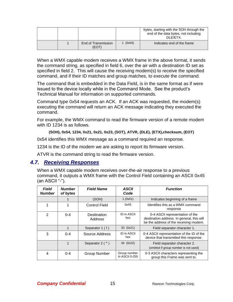
When a WMX capable modem receives a WMX frame in the above format, it sends the command string, as specified in field 6, over the air with a destination ID set as specified in field 2. This will cause the receiving modem(s) to receive the specified command, and if their ID matches and group matches, to execute the command.
The command that is embedded in the Data Field, is in the same format as if were issued to the device locally while in the Command Mode. See the product’s Technical Manual for information on supported commands.
Command type 0x54 requests an ACK. If an ACK was requested, the modem(s) executing the command will return an ACK message indicating they executed the command.
For example, the WMX command to read the firmware version of a remote modem with ID 1234 is as follows.
(SOH), 0x54, 1234, 0x21, 0x21, 0x23, (SOT), ATVR, (DLE), (ETX),checksum, (EOT)
0x54 identifies this WMX message as a command required an response.
1234 is the ID of the modem we are asking to report its firmware version.
ATVR is the command string to read the firmware version.
4.7. Receiving Responses
When a WMX capable modem receives over-the-air response to a previous command, it outputs a WMX frame with the Control Field containing an ASCII 0x45 (an ASCII “-”).
Field Number
Number of bytes
Field Name ASCII Code
Function
1 (SOH) 1 (0x01) Indicates beginning of a frame
1 1 Control Field 0x45 Identifies this as a WMX command response
2 0-4 Destination Address
ID in ASCII hex
0-4 ASCII representation of the destination address. In general, this will be the address of the receiving modem.
1 Separator 1 ( ! ) 33 (0x21) Field separator character 1.
3 0-4 Source Address ID in ASCII hex
0-4 ASCII representation of the ID of the device that transmitted this response.
1 Separator 2 ( “ ) 34 (0x22) Field separator character 2.
(omitted if group number is not used)
4 0-4 Group Number Group number in ASCII 0-255
0-3 ASCII characters representing the group this Frame was sent to.

Company Confidential 16 Raveon Technologies Corp.
1 Separator 3 ( # ) 35 (0x23) Record separator character 3 (when transmitting, may be left out if sequence
field is not used)
5 0-4 Sequence ASCII number 0-255
A sequence number for this transmission to uniquely identify it.
1 Separator 4 ( $ ) 36 (0x24) Record separator character 4 Optional RSSI
6 0-3 RSSI ASCII number 0-127
Receive signal strength in negative dBm.
1 Start of Text (SOT) 2 (0x02) Indicates beginning of data
7 1-500 Data Field The response bytes received over the air.
2 End of Text 0x10 0x03 ETX end of the data frame
8 0 - 4 Checksum 0-FFFF The 16-bit checksum of all the previous bytes, starting with the SOH through the
end of the data bytes, not including DLE/ETX.
1 (EOT) 1 (0x04) Indicates end of the frame
The control field is always a 0x45 for WMX responses.
When a WMX capable modem receives a response back from another modem over the air (with the correct ID), it outputs the response data it receives in a WMX frame as shown above. The ID of the unit that transmitted the data is in field 3, the Source Address. The ID that the data was sent to is in field 2, the Destination ID. The Control Field contains a 0x42.
If the command that instigated the response was properly executed, the Data Filed will have an OK<13> in it.
4.8. Modem Status Responses
Transmitting data with control field 0x60 operates identical to control field 0x40 with the exception that up to two messages will be generated by the transmitting modem. The messages will indicate the status of sending the message over-the-air, using the following format:

Company Confidential 17 Raveon Technologies Corp.
Field Number
Number of bytes
Field Name ASCII Code
Function
1 (SOH) 1 (0x01) Indicates beginning of a frame
1 1 Control Field 0x47 Identifies this as a modem status message
2 4 Destination Address
ID in ASCII hex
0-4 ASCII representation of the destination address. This will be set to the
source address from the original message
1 Separator 1 ( ! ) 33 (0x21) Field separator character 1.
3 0-4 Source Address ID in ASCII hex
0-4 ASCII representation of the ID of the radio generating the status message (the
local, transmitting radio)
1 Separator 3 ( # ) 35 (0x23) Record separator character 3
5 0-4 Sequence ASCII number 0-255
A sequence number for this message to uniquely identify it.
This sequence number is unrelated to the sequence number of the original message whose status is being provided.
1 Start of Text (SOT) 2 (0x02) Indicates beginning of data
7 1-500 Data Field Modem status information (see below)
2 End of Text 0x10 0x03 ETX end of the data frame
8 0 - 4 Checksum 0-FFFF The 16-bit checksum of all the previous bytes, starting with the SOH through the
end of the data bytes, not including DLE/ETX.
1 (EOT) 1 (0x04) Indicates end of the frame
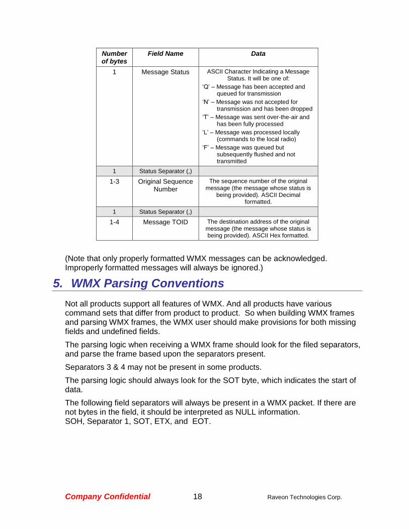
Modem Status Data Field
A modem status message will have a data field with the following format:
Company Confidential 18 Raveon Technologies Corp.
Number of bytes
Field Name Data
1 Message Status ASCII Character Indicating a Message Status. It will be one of:
‘Q’ – Message has been accepted and queued for transmission
‘N’ – Message was not accepted for transmission and has been dropped
‘T’ – Message was sent over-the-air and has been fully processed
‘L’ – Message was processed locally (commands to the local radio)
‘F’ – Message was queued but subsequently flushed and not transmitted
1 Status Separator (,)
1-3 Original Sequence Number
The sequence number of the original message (the message whose status is
being provided). ASCII Decimal formatted.
1 Status Separator (,)
1-4 Message TOID The destination address of the original message (the message whose status is being provided). ASCII Hex formatted.
(Note that only properly formatted WMX messages can be acknowledged. Improperly formatted messages will always be ignored.)
5. WMX Parsing Conventions
Not all products support all features of WMX. And all products have various command sets that differ from product to product. So when building WMX frames and parsing WMX frames, the WMX user should make provisions for both missing fields and undefined fields.
The parsing logic when receiving a WMX frame should look for the filed separators, and parse the frame based upon the separators present.
Separators 3 & 4 may not be present in some products.
The parsing logic should always look for the SOT byte, which indicates the start of data.
The following field separators will always be present in a WMX packet. If there are not bytes in the field, it should be interpreted as NULL information. SOH, Separator 1, SOT, ETX, and EOT.