wireless mesh network concepts and best practices guide
DESCRIPTION
Mesh Network conceptsTRANSCRIPT

Wireless Mesh Network Concepts and Best Practices Guide

© 2010, Schneider Electric
All Rights Reserved
No part of this publication may be reproduced, read or stored in a retrieval system, or transmitted, in any form or by any means, electronic, mechanical, photocopying, recording, or otherwise, without prior written permission of Schneider Electric.
This document is produced in the United States of America.
Product Names are trademarks of Schneider Electric. All other trademarks are the property of their respective owners.
Title: Wireless Mesh Networking Concepts and Best Practices Guide
Revision: C
Date: November, 2010
Schneider Electric part number: 30-3001-912
For bCX1 40x0 BACnet controllers running software version 4.5 and bCX1 9640 Infinet controllers running software version 1.2
The information in this document is furnished for informational purposes only, is subject to change without notice, and should not be construed as a commitment by Schneider Electric. Schneider Electric assumes no liability for any errors or inaccuracies that may appear in this document.
Schneider Electric One High Street North Andover, MA 01845 (978) 975-9600 Fax: (978) 975-9782 http://www.schneider-electric.com/buildings

Wireless Mesh Network Concepts and Best Practices Guide
30-3001-912Revision C
November, 2010


Contents
About this Manual ................................................................. 7Chapter 1 Introduction to Wireless ...................................................... 9
Networks are Evolving ................................................................... 10Traditional Hard-Wired Networks ................................................. 11
LANs .............................................................................................. 11Internet .......................................................................................... 12
Overview of Wireless Networks ..................................................... 13Wireless Terminology ................................................................... 13Successful Wireless Communication ........................................... 15
Wireless propagation changes over time ................................... 15Background noise ........................................................................ 15Obstacles in proximity with the network .................................. 15Changes in link quality .............................................................. 16Minimized propagation delay in wireless networks .................. 16
Network Topologies ....................................................................... 17Point to Point .............................................................................. 18Point to Multipoint ...................................................................... 18Star Network Topology ............................................................... 18
Advantages of star networks .................................................... 20Disadvantages of star networks ............................................... 20
Mesh Network Topology ............................................................. 20Design Considerations for Wireless Mesh Networks .................... 22
Reliability and Adaptability ......................................................... 22Scalability ...................................................................................... 23Redundancy ................................................................................... 23Self-Configuring ............................................................................ 23Self-Healing ................................................................................... 24Self-Discovery and Automatic Routing ........................................ 24
Proactive discovery ..................................................................... 24On-demand discovery ................................................................. 25Single path routing ..................................................................... 25Dynamic routing ......................................................................... 27
Wireless Network Installation and Operational Benefits ............ 28
Wireless Mesh Network Concepts and Best Practices Guide 5

Table of Contents
Installation .................................................................................... 28Distributed Control ....................................................................... 28Monitoring and Maintenance ....................................................... 29
Maintenance considerations ....................................................... 30Chapter 2 The Andover Continuum Wireless Solution ...................... 33
Andover Continuum Wireless Technology .................................... 34Overview ........................................................................................ 34Continuum Wireless Devices ....................................................... 35
Wireless Adapter ......................................................................... 35Wireless Repeater ....................................................................... 36
Wireless Maintenance Tool .......................................................... 37Wireless Adapter Display ........................................................... 38Wireless Adapter Table .............................................................. 39Adapter Service Cable and Service Software ............................ 39
Preventing RF Interference with Other Wireless Devices ......... 39Schneider Electric Wireless Adapter/Repeater RF Channel Consider-ations ........................................................................................... 40
Guidelines for CyberStation Wireless Control .............................. 42CyberStation Wireless CommPort Control ................................. 42
Setting the CommPort ................................................................ 42Performing a Learn Process ....................................................... 44
CyberStation Control of Wireless Network Traffic ..................... 45Wireless Network Traffic and Data Collection Methods .......... 45Wireless Network Traffic and APDU Timeouts ........................ 46
CyberStation Control of Guaranteed Alarms (BACnet) ............. 46Guidelines for Designing Your Wireless Solution ......................... 48
Major Design Factors .................................................................... 49Site Surveys .................................................................................. 49Adapter and Repeater Placement ................................................ 50New Wireless Installations .......................................................... 51Replacing Older Networks ........................................................... 51
Appendix A Frequently Asked Questions About Wireless Controls and Do’s and Don’t s ............................................................................ 53Questions and Answers about Wireless Controls ......................... 54
Do’s and Don’ts of Wireless .......................................................... 57
6 Schneider Electric

About this Manual
This manual provides a brief introduction to wireless networking and how the technology is applied, as an Andover Continuum solution, to control a network of HVAC controllers.
The discussion begins with acknowledging the traditional hard-wired networks, such as local area networks (LANs) and the Internet, that we use everyday.
Then, the manual introduces the concept of a wireless network and presents an overview of wireless network components, different types of wireless networks, and the benefits of wireless over hard-wired networks.
And finally, the manual describes the Andover Continuum application of wireless technology for controlling and deploying a wireless HVAC solution. The Andover Continuum solution results in cost reductions for installation, maintenance and distributed control over hard-wired HVAC controllers and devices.
Wireless Mesh Networking Concepts and Best Practices Guide 7

About this Manual
8 Schneider Electric

Chapter 1Introduction to Wireless
This chapter contains the following topics:
Networks are EvolvingTraditional Hard-Wired NetworksOverview of Wireless NetworksDesign Considerations for Wireless Mesh NetworksWireless Network Installation and Operational Benefits
Wireless Mesh Networking Concepts and Best Practices Guide 9

Chapter 1: Introduction to Wireless
Networks are Evolving
Within the past 40 years, networking technology has undergone significant changes, and yet the primary mission of a network has remained the same, to share information.
When IBM introduced the SNA architecture, we saw the network as a means to record and distribute information from a large central mainframe. We typed in an entire page of information using a “dumb” terminal and pressed the Enter key to deliver it while we waited for the mainframe to respond with a new page of fields and values.
Later, as PCs were introduced and became more powerful, the concept of a de-centralized distributed network was considered a more flexible architecture. Networks of servers and workstations could be small, medium or large, and provide all the software applications, tailored to a company’s, institution’s, or organization’s needs.
As networks evolved, we found we could use networks to capture information from individual devices and controllers in dispersed locations, and then add their input to our existing network traffic to help us automate and monitor these devices centrally.
The rise of the Internet multiplied the initial decentralized distributed network concept into a world wide network of data, images and applications.
Throughout this evolution, equipment, computing power, communication protocols, and applications have grown and networks have become the standard application for sharing information across an almost unlimited amount of applications and geographical boundaries.
This chapter discusses how to use the next evolution of network technology — wireless mesh technology — to help improve the automation and control of a dedicated HVAC network, while also saving costs and the overhead expenses of a typical hard-wired network.
10 Schneider Electric

Chapter 1: Introduction to Wireless
Traditional Hard-Wired Networks
Although wireless technology is relatively new, a wireless network is not that much different from two of the most common types of network we are all familiar with today: a Local Area Network (LAN), and the Internet.
The following paragraphs provide a brief review of LAN and Internet concepts.
LANs
When many of us boot up our computer, we are automatically connected to our company’s or organization’s LAN. Most LANs cover a small geographical area, such as a building or campus, and include individual PCs and workstations that are referred to as nodes. Each node has its own CPU and can execute programs individually, while also having the option of using programs and accessing data from servers anywhere on the network.
LANs are capable of transmitting data at very fast rates, but the distances are limited, and there is also a limit to the number of computers that can be attached to a single LAN.
There are many different types of LANs. The following characteristics differentiate one LAN from another:
Topology — The structure used to connect devices on a network. For example, devices can be arranged in a ring or a straight line.Protocols — The rules and encoding specifications. Protocols also determine whether the network uses peer-to-peer or client/server architecture.Media — Devices can be connected by twisted-pair cables, coaxial cables, fiber optic cables or by wireless connections.
Wireless Mesh Networking Concepts and Best Practices Guide 11

Chapter 1: Introduction to Wireless
Internet
The Internet is a network of networks in which users at any one computer can, if they have permission, send and receive information to or from any other computer connected to the Internet.
The Internet is a public, cooperative, and self-sustaining facility accessible to hundreds of millions of people worldwide. Physically, the Internet uses a portion of the existing public telecommunications networks.
Technically, the Internet uses a set of protocols called TCP/IP (Transmission Control Protocol/Internet Protocol). Private sections of the Internet, such as intranets and extranets, also use the TCP/IP protocol.
The most commonly used features of the Internet are:
World Wide Web — Using a Web browser, such as Microsoft Internet Explorer, you can access millions of pages of information that are instantly cross referenced using “clickable” hypertext links. Electronic mail (email) — Allows you to send and receive short, written notes to other computer users. Voice over Internet Protocol (VoIP) — Telephony hardware and software allows real-time voice conversations over the Internet.
12 Schneider Electric

Chapter 1: Introduction to Wireless
Overview of Wireless Networks
This section describes an overview of wireless networks, with a brief introduction to several types of wireless network topologies and the benefits and features of each design.
Wireless Terminology
Wireless technology is based upon embedding RF components (low-cost, low-power radios and microcontrollers) directly into a product. Embedded RF uses high quality, low-cost, radio frequency integrated circuit (RFIC) technology.
The following definitions describe some basic wireless terminology:
Node — An addressable device on a wireless network. The wireless node can sometimes be defined as both an adapter and a controller. The distance between each node is called a “hop”.The following illustration is a representation of a Schneider Electric wireless node.
Repeater — A node that strengthens a mesh network.Link — In a mesh network, a link is a single hop relationship between neighbor nodes. A link is duplex and travels in two directions.
Wireless Mesh Networking Concepts and Best Practices Guide 13
Chapter 1: Introduction to Wireless
Link Strength — The quality of the reception signal from a neighbor node.Link Quality Indicator — Link strength and other factors that indicate a node’s ability to receive error free messages.
Asymmetric Link — A link where one side has drastically poorer reception quality than the other side. Reasons for this type of link include loud noise near the node with the poorest reception, multi-path problems in one direction or power output differences.
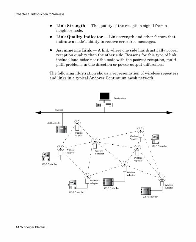
The following illustration shows a representation of wireless repeaters and links in a typical Andover Continuum mesh network.
14 Schneider Electric

Chapter 1: Introduction to Wireless
Successful Wireless Communication
Despite the benefits of wireless communication, there are undeniable challenges for all wireless networks. Perhaps the most difficult challenge is with signal propagation. These challenges are described in the following paragraphs.
Wireless propagation changes over time
Propagation fluctuates moment by moment due to changing natural and manmade conditions. For example, links in a factory that appear strong and reliable during deployment may be rendered completely unusable after the installation of a new industrial machine.
Background noise
All communication depends on separating the useful radio signal from the background noise, and when there is a lot of background noise, it is difficult to get signal through.
The ambient noise level is due primarily to atmospheric conditions and local noise sources. In actual deployments the noise floor is varying constantly, and the intensity of the noise can rise and fall by tens of decibels. Very often, this is the major reason for changes in link quality.
Obstacles in proximity with the network
Propagation can vary due to obstacles moving in and out of proximity with the network. For example, networks set up in modern office buildings can vary dramatically when cubicles are rearranged.
RF is affected by walls, doors, windows, concrete, metal objects, and even people. The higher the frequency, the greater the impact; most importantly, the greatest impact is on range limitation.
Sometimes an obstacle is obvious, such as when a delivery truck blocks an access point. At other times, an obstacle is more subtle, such as when reflective surfaces, such as water pipes, create multiple pathways for the radio waves. This condition is called “multipath”, and it can degrade link quality through destructive interference of the signal traveling via two paths of different lengths.
Wireless Mesh Networking Concepts and Best Practices Guide 15

Chapter 1: Introduction to Wireless
Changes in link quality
Changes in link quality can lead to variations in signal propagation. There are many causes for changes in link quality, such as the following:
The performance of outdoor wireless networks can change significantly from sunny weather to rain or from summer to winter. Changes in temperature, relative humidity, and even atmospheric events like sunspots can alter RF signal quality.Wireless networks are susceptible to interference from electronic devices such as, office equipment, Wi-Fi hotspots, cell phones, rotating machinery, and microwave ovens. The most likely service degradation arises from “multipath” reception, described in the previous section.Wireless networks may perform well at night when the building is empty, but marginally when the workers arrive. The human body is essentially a water-filled obstruction to an RF network.
Minimized propagation delay in wireless networks
Fluctuations in signal quality cannot be prevented, but you can use a number of strategies to reduce its impact on signal propagation. For example:
Reduce link distances between nodesIncrease transmitter powerUse better antennasAdd nodes to produce alternate (redundant) pathways
Low power, multi-hop networks take advantage of the highly localized nature of propagation changes by designing alternate message pathways with dynamic routing. Using embedded RF, acceptable levels of network reliability can be achieved with lower-cost devices.
16 Schneider Electric

Chapter 1: Introduction to Wireless
Network Topologies
A wireless network can have different topologies, or organizations, depending on the ways in which messages need to flow from one node to another. A topology is established, based on answers to fundamental questions, such as:
Will a number of sensors report their controller data to an aggregation point?What happens if a message destination is out of range of the message originator?How will messages be relayed?How will the network recover from the loss of a route?
This section covers the following links and topologies:
Point to point linksPoint to multipoint linksStar networksMesh networks
Note: Andover Continuum wireless networks are mesh networks. (See Mesh Networks, later in this section.) However, this section presents an overview of all wireless topologies to give you a basic understanding of what’s typically used today in wireless applications.
Wireless Mesh Networking Concepts and Best Practices Guide 17

Chapter 1: Introduction to Wireless
Point to Point
A point-to-point link, also called a wireless bridge, connects two nodes. It serves as a wireless replacement for a single communication cable, as shown below.
Point-to-point links can communicate reliably, as long as the two nodes are located close enough to one another to escape the effects of RF interference and signal path loss. As with all wireless communication, if a reliable connection is not achieved initially, it is sometimes possible to relocate the radios or boost the transmit power to achieve the desired result.
Point to Multipoint
Point-to-multipoint links, also called a hub and spoke, have one central-point node that controls communication with all of the other wireless nodes in the network. Signals in point-to-multipoint communication converge at the central-point node. The reliability of this communication depends on the quality of the RF link between the central point and endpoint. Point-to-point communication is used in star network topology. (See Star Network Topology, later in this section.)
Star Network Topology
Networks based on star topology provide efficient, localized (“one hop”) communication. In these networks, a hub node arbitrates all communication with other nodes. All traffic to and from end nodes
18 Schneider Electric

Chapter 1: Introduction to Wireless
flows through the hub. The following diagram shows star network topology.
An example of a star network topology would be a Wi-Fi network where the access point is the hub and a laptop may be a node.
Wireless Mesh Networking Concepts and Best Practices Guide 19

Chapter 1: Introduction to Wireless
Advantages of star networks
Star networks are simple to implement. Because the central node arbitrates all communications within the star, routing and multiple-access problems become very simple to manage. Timing control is centralized, so it is easy to analyze. Nodes transmit directly to the master. Properly-designed applications can use most of the bandwith available on the radio.
Disadvantages of star networks
Since the central node must interact with every node, the central node’s radio limits the geographic spread of the network. Also, when physical or RF interference blocks communication between the access point and any of the nodes, the network cannot recover until the source of interference is removed.
Mesh Network Topology
Note: Andover Continuum wireless networks are mesh networks. (See also Chapter 2.)
Mesh (multi-hop) networks are different from Star networks because every node can communicate with any other node or multiple nodes within the network. This form of communication is called routing.
A node can send and receive messages, but in a mesh network, a node also functions as a router and can relay messages for its neighbors. Through this relaying process, a packet of wireless data finds its way to its ultimate destination, passing through intermediate nodes and repeaters with reliable communication links.
20 Schneider Electric

Chapter 1: Introduction to Wireless
The illustration below shows an example of a wireless mesh network. (See also, Chapter 2.)
Routing involves relaying messages among multiple, interim nodes when messages are communicated from a sending node to a destination node. For example, if Node A needs to send a message to Node E, then this type of communication allows it to get relayed (routed) through Nodes B, C, D and so on. Routing is used in mesh network topology. (See Self-discovery and automatic routing, later in this section.)
Wireless Mesh Networking Concepts and Best Practices Guide 21

Chapter 1: Introduction to Wireless
Design Considerations for Wireless Mesh Networks
Wireless mesh networks for the HVAC/building controls industry consist primarily of wireless control and sensor networks. Characteristics of these networks include:
Low data rates — controllers send sensor data, providing information like temperature, pressure, and flowLow cost — when compared to the cost of hard wiringLow power consumption — low-power radios and micro-controllers are imbedded directly into a product
The design objectives for control and sensing networks are reliability, adaptability, scalability and redundancy.
The following sections describe these important design considerations:
ReliabilityAdaptabilityScalabilityRedundancySelf-configuringSelf-healingSelf-discovery and automatic routing
Reliability and Adaptability
Wireless systems must be just as reliable as traditional copper wire. Depending on the application, dropped data can result in anything from a disruptive glitch to a devastating failure.
The network should adapt to the existing environment. The environment should not have to be altered to make the system “wireless ready”.
22 Schneider Electric

Chapter 1: Introduction to Wireless
In the wireless world, the network should integrate seamlessly with the environment. A key attribute of a good wireless network is that daily work activities and the facility layout are not a concern. A mesh network can actually be more reliable than a wired network.
Scalability
Any network, wired or wireless, should scale gracefully as the number of nodes increases. A mesh network is scalable by adding freestanding “repeater” nodes in the middle of the network. A mesh network can handle hundreds of nodes.
Since the operation of a mesh network does not depend on a central control point, adding multiple data collection points or gateways is not that different than adding another node to the mesh.
Redundancy
In a mesh network, the degree of redundancy is essentially a function of node density. In an ideal mesh network, a node should have several overlapping neighbors so that each device has two or more paths for sending data. This is an easier way of obtaining redundancy than is possible in most other types of systems.
Self-Configuring
A network should not need a person to tell it how to move a packet from one end to the other. A mesh network is self-organizing and does not require manual configuration.
Because it is self-configuring, adding new gear or relocating gear is as simple as installing a wireless node and turning it on. The network discovers the new node and automatically incorporates it into the network without the need for a system administrator.
Wireless Mesh Networking Concepts and Best Practices Guide 23
Chapter 1: Introduction to Wireless
Self-Healing
Mesh networks are both self-configuring and self-healing. If a device in a mesh network fails, messages are sent around it via other devices. Loss of one or more nodes does not necessarily affect its operation.
A mesh network is also self-healing because human intervention is not necessary for re-routing messages.
Self-Discovery and Automatic Routing
Automatic network analysis through link and route discovery are the distinguishing features of self-healing networks. Through discovery, networks establish one or more routes between the originator and the recipient of a message. Through route evaluation, networks detect route failures, trigger renewed discovery, and — in some cases — select the best route available for a given message.
Wireless self-healing networks have several options for discovery and routing:
Proactive discoveryOn-demand discoverySingle path routingDynamic routing
The choice of discovery and routing schemes affects network latency, throughput, resource needs, and power consumption in varying amounts.
Proactive discovery
Proactive discovery causes routes to be discovered before messages need to be routed. They assume that link breakages and performance changes are always happening and are structured to continuously discover and reinforce optimal linkages.
24 Schneider Electric

Chapter 1: Introduction to Wireless
Any node in the mesh is “always on”, so as to forward or route messages. Proactive discovery “refreshes” routes at a rate that, if done properly, does not strain the available bandwidth. Also, because the network is always on, it is more difficult to conserve power.
Note: Andover Continuum uses proactive discovery.
On-demand discovery
On-demand discovery networks, by contrast, only establish routes that are requested by higher-level software, and only discover routes when needed. This allows nodes to conserve power and bandwidth and keeps the network fairly free of traffic.
However, if between transmissions the link quality between nodes has degraded, it can take on-demand networks longer to reconfigure and deliver a message.
Single path routing
Network algorithms that choose single path routing for messages single out a specific route for a given source-destination pair. Sometimes the entire end-to-end route is predetermined. Sometimes, it’s just the next “hop” that is known.
Wireless Mesh Networking Concepts and Best Practices Guide 25

Chapter 1: Introduction to Wireless
The illustration below shows “end-to-end” single path routing.
The advantage of single path routing is that it cuts down on traffic, bandwith use, and power use. If only one node at a time needs to receive the packet, others can stop listening after they hear that they’re not the recipient.
The disadvantage of single path routing is high latency or even non-delivery. If any links along the route are degraded or broken, the packet will not get through, and depending on the maintenance scheme, it can take a long time for the network to recover enough to build a new route.
26 Schneider Electric

Chapter 1: Introduction to Wireless
Dynamic routing
Dynamic routing takes advantage of the broadcast nature of the wireless medium. Messages are forwarded to the ultimate destination using the path of least resistance. Upon receiving a packet transmission, the neighbor that has the least cost to the ultimate destination, forwards the packet first, while the other neighbors, receiving the repeated packet do not forward the transmission. The updated cost is included in the transmission, so nodes that have an equal or greater cost do not forward the packet. “Cost” refers to the number of hops (and signal strength) to reach a specified destination.
The illustration below shows an example of dynamic routing.
If a node along the optimal route is unable to forward the message, because it is busy or offline, dynamic routing will allow the message to flow along a different route.
Note: Andover Continuum uses dynamic routing.
Wireless Mesh Networking Concepts and Best Practices Guide 27

Chapter 1: Introduction to Wireless
Wireless Network Installation and Operational Benefits
This section summarizes the benefits of installing and using wireless networks.
Installation
The most obvious benefit of installing a wireless system is the cost savings from not having to install wiring. Using an RF communication link to emulate wire saves greatly on the cost of wiring.
Another benefit of installing a wireless system is the speed of deployment. Wired systems can take days or weeks to be properly installed, isolated, or commissioned. Wireless networks require only the nodes to be installed, savings hours or days for each instrument installed. Other instruments can be added as required, without the need for expensive, disruptive cabling and labor.
Finally, since wireless mesh networks are self-configuring, you eliminate the need for high level system administration.
Distributed Control
Wireless, multi-hop, mesh networks provide a unique opportunity to use distributed control.
The control of the wireless system is distributed throughout the network, allowing intelligent peers to communicate directly to other points on the network without having to be routed through some central point.
28 Schneider Electric

Chapter 1: Introduction to Wireless
The illustration below shows an example of distributed control in a wireless mesh network.
Monitoring and Maintenance
Wireless, multi-hop, mesh networks simplify the diagnostic monitoring of devices because the monitoring can occur outside the normal control loop and wireless communication can be sent to notify maintenance personnel of any abnormal operation of the device.
Wireless Mesh Networking Concepts and Best Practices Guide 29

Chapter 1: Introduction to Wireless
For example, consider the schematic of a sensor control loop shown in the following illustration.
In this control loop, an additional signal is extracted and analyzed during the course of normal operation of the sensor. As the sensor operates, the signal is monitored for abnormalities without affecting the sensor’s operation. If an abnormal signal or trend is observed, an alert is triggered.
The major benefit of using a wireless link for on-board monitoring is that the monitoring link remains independent of the control loop. Data can be routed dynamically to similar wireless devices. Surrounding devices can respond to the alert from the failing device, even as the alert is being sent to maintenance personnel.
Maintenance considerations
Another benefit of wireless systems is that maintenance personnel can directly connect to diagnostic output without running wires. For example, this could eliminate a huge task in the case of a tank level sensor in a large storage tank, or a temperature probe at the top of a tower stack.
30 Schneider Electric
Chapter 1: Introduction to Wireless
In a wireless, multi-hop mesh network, maintenance personnel can get data via any wireless device on the network. By using a diagnostic device with additional processing power (such as a laptop computer or handheld diagnostic device) maintenance personnel can check on configuration and other information about any node on the network.
Wireless Mesh Networking Concepts and Best Practices Guide 31

Chapter 1: Introduction to Wireless
32 Schneider Electric

Chapter 2The Andover Continuum Wireless Solution
This chapter contains the following topics:
Andover Continuum Wireless TechnologyGuidelines for CyberStation Wireless ControlGuidelines for Designing Your Wireless Solution
Wireless Mesh Networking Concepts and Best Practices Guide 33

Chapter 2: The Andover Continuum Wireless Solution
Andover Continuum Wireless Technology
Overview
This section presents an overview of Andover Continuum wireless technology. For complete information, please see the documentation that is referenced in this chapter.
Building automation companies looking for an energy-efficient, competitive edge are developing wireless network products for the complex internal HVAC, lighting, and safety systems of urban buildings.
Andover Continuum’s building automation control system has developed wireless technology that consists of the following components and communication concepts:
Wireless devices (adapters and repeaters) that allow users to create a wireless mesh network segment connecting BACnet (b3) or Infinet II (i2) controllers with each other. A Wireless Maintenance Tool (WMT) to help users design and maintain a stable and robust wireless mesh network. The WMT includes a service cable and related service software.CyberStation software attributes to configure a controller’s communication port as “wireless” and a “learn” process to discover and integrate wireless controllers seamlessly into a Continuum network. CyberStation can also minimize wireless network traffic via controls that govern data collection, data polling, and application protocol data units (APDU) transmission timeouts.Andover Continuum supports up to 32 b3 or i2 wireless field bus controller nodes per bCX1 controller. You can add additional bCX1 controllers to expand the wireless network by multiples of 32 wireless field controllers. (See the illustration on the next page.)An internal routing table in the bCX1 controller relays messages from other controllers on the Ethernet (outside the wireless mesh network) to the field bus controllers in the wireless mesh network.
34 Schneider Electric

Chapter 2: The Andover Continuum Wireless Solution
Continuum Wireless Devices
Continuum wireless devices allow Continuum controllers to communicate with other controllers across a wireless field bus mesh network. The Andover Continuum Wireless Adapter is a single device that can perform two roles — adapter and repeater.
The following illustration shows a wireless field bus mesh network.
Note: Each bCX1 controller Adapter up to 32 field bus controller nodes (i2 or b3).
Wireless Adapter
As a Wireless Adapter, the device is attached to the RS-485 Service (Comm) Port of the BACnet/Infinet bCX1 controllers, Infinet II (i2) field bus controllers, and BACnet (b3) field bus controllers. This allows the field bus controller to communicate with other controllers across a wireless mesh network.
i2/b3 Controller
i2/b3 Controller
i2/b3 Controller
i2/b3 Controller
i2/b3 Controller
bCX Controller
Wireless Repeater
Wireless Repeater
WirelessAdapter
WirelessAdapter
WirelessAdapter
WirelessAdapter
WirelessAdapter
Ethernet
Workstation
WirelessAdapter
Wireless Mesh Networking Concepts and Best Practices Guide 35

Chapter 2: The Andover Continuum Wireless Solution
The Wireless Adapter replaces the normal hard-wired network connection between controllers, and allows controllers to function as if a hard-wired network connection was in place with some limitations. Power to the Wireless Adapter is supplied by the controller.
The illustration below shows a Wireless Adapter connected to a controller.
Wireless Repeater
As a Wireless Repeater, the device is used to provide redundant links between Wireless Adapters connected to field bus controllers. When used as a Wireless Repeater, the device is not connected to a controller, and can be installed anywhere.
A repeater may be needed when there are long distances between wireless-enabled controllers, to add additional network paths for redundancy, or to compensate for obstacles, such as pipes or walls that can attenuate or weaken the wireless signal between controllers.
The repeater requires a 3.3 — 5 VDC ± 5%, 75 mA power supply.
Note: To order the Repeater power supply from Schneider Electric, use part number WL-RPTR-PS.
The following illustration shows a Wireless Repeater connected to a power supply.
CPU
INFINET (YELLOW)
BACNET (GREEN)
RESTART
COMM
PORT 1RS-232(DTE)
N ( )
L ( )
INPUT POWER24 VAC40
VA50/60 HZ12-28
VDC 25W
xP EXPPORT
24
VDC400mA
DCDRTSRDTD
RD
TD
SHLD
SERVICE
C
MM
P
RT
2
PORT
RS-485
ETHERNET10/100BASE T
RS 232
LINK/ACT 10/10
0Mbps
Controller RS- 485 Service Port
Supplied 6 foot cable
* Adapters with 25 foot cables are also available
WirelessAdapter
36 Schneider Electric

Chapter 2: The Andover Continuum Wireless Solution
For more information, please see the Andover Continuum Wireless Adapter/Repeater Installation Instructions, 30-3001-887.
Wireless Maintenance Tool
The Wireless Maintenance Tool (WMT) is a Windows-based application that shows you a wireless mesh network of adapters and repeaters in an interactive graphic display. From the display, you can gather information and monitor the communication details and signal strengths for each Wireless Adapter and connection.
You can also use the WMT to change the Wireless Adapter settings for transmission power, RF channel, and PAN ID. You can also update the adapter firmware from the WMT.
Wireless Mesh Networking Concepts and Best Practices Guide 37
Chapter 2: The Andover Continuum Wireless Solution
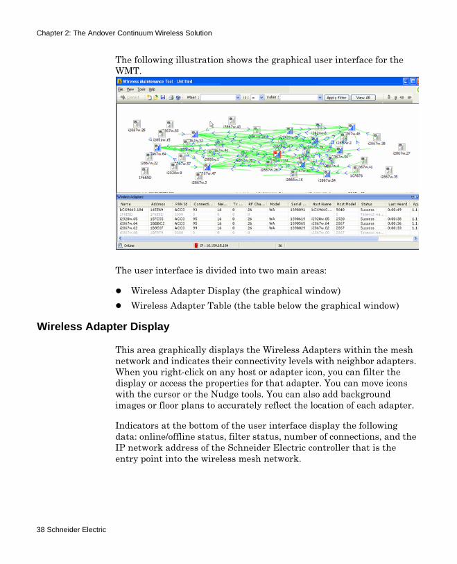
The following illustration shows the graphical user interface for the WMT.
The user interface is divided into two main areas:
Wireless Adapter Display (the graphical window)Wireless Adapter Table (the table below the graphical window)
Wireless Adapter Display
This area graphically displays the Wireless Adapters within the mesh network and indicates their connectivity levels with neighbor adapters. When you right-click on any host or adapter icon, you can filter the display or access the properties for that adapter. You can move icons with the cursor or the Nudge tools. You can also add background images or floor plans to accurately reflect the location of each adapter.
Indicators at the bottom of the user interface display the following data: online/offline status, filter status, number of connections, and the IP network address of the Schneider Electric controller that is the entry point into the wireless mesh network.
38 Schneider Electric

Chapter 2: The Andover Continuum Wireless Solution
Wireless Adapter Table
The Wireless Adapter Table lists each adapter in the Wireless Adapter display area, along with all their property values. You can select each property and access object menus to filter the table and view or edit the properties of the selected Wireless Adapter.
Adapter Service Cable and Service Software
The Adapter Service Cable and Service Software that is embedded in the Wireless Adapter enable you to make changes to selected Wireless Adapter properties and to upload new adapter firmware. The cable and software are available in addition to the WMT for changing Wireless Adapter settings and updating firmware.
You may want to use them to specify settings in Wireless Adapters that are not yet online in your mesh network or that are unable to communicate with other Wireless Adapters in the network.
Preventing RF Interference with Other Wireless Devices
When you are planning the installation of a wireless building automation system (BAS) it is necessary to consider the possibility of interference with other wireless devices and systems in the building.
Most BAS wireless devices utilize the IEEE 802.15.4 standard (including ZigBee), while wireless local area computer networks utilize the IEEE 802.11 standard (also known as Wi-Fi). Because both networks occupy the unlicensed industrial, scientific, and medical 2.4 Ghz band, interference among them can occur when they are in close proximity and/or when their deployment is ungoverned by a channel utilization plan.
Both the IEEE 802.15.4 and IEEE 802.11 protocols are based on the carrier-sense multiple-access/collision avoidance (CSMA/CA) channel access method. Using this method, each node listens for another node’s carrier before transmitting a request to assert itself as the transmitting node. All nodes of that protocol within receiving distance refrain from transmitting for a random period of time (defined by the applicable IEEE standard), thus allowing the transmitting node to occupy the channel.
Wireless Mesh Networking Concepts and Best Practices Guide 39

Chapter 2: The Andover Continuum Wireless Solution
Because IEEE 802.11 RTS messages are protocol-specific, they are not understood by IEEE 802.14.5 nodes and vice versa. However, if an 802.11 node and an 802.14.5 node transmit at the same time on the same channel, they will interfere with each other. This is how interference between the two networks can occur.
Testing shows the two factors that affect the performance of IEEE 802.14.5 networks in the presence of Wi-Fi are:
Proximity to the Wi-Fi nodesTraffic volume on the Wi-Fi network
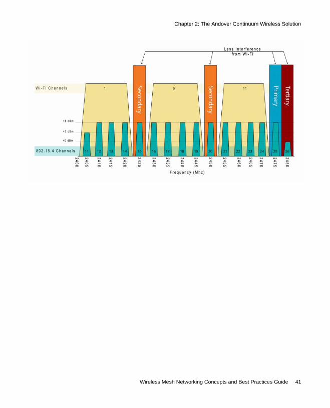
Schneider Electric Wireless Adapter/Repeater RF Channel Considerations
The default radio frequency (RF) channel for the Schneider Electric Wireless Adapter/Repeater is 25, but you can change the RF channel. Schneider Electric chose channel 25 because the frequency is beyond the frequencies of commonly used Wi-Fi channels, eliminating many potential conflicts.
Other suggested alternative RF channel selections include:
Channels 15 and 20, which are clear channels between common Wi-Fi channels Channel 26, which is beyond the frequencies of commonly used Wi-Fi channels but has a maximum power limitation of 0 dBm (Most other Schneider Electric Wireless Adapter/Repeater channels have a maximum power limit of 6 dBm.)
The following illustration shows a comparison between the IEEE 802.14.5 RF channels and common Wi-Fi RF channels.
40 Schneider Electric
Chapter 2: The Andover Continuum Wireless Solution
Wireless Mesh Networking Concepts and Best Practices Guide 41

Chapter 2: The Andover Continuum Wireless Solution
Guidelines for CyberStation Wireless Control
The following sections present some general information about the ways in which Andover Continuum CyberStation software controls a wireless network.
CyberStation Wireless CommPort Control
There are two CyberStation software attributes for wireless networks:
The comm port on your on your network controller must have the Default Mode set to “Wireless.”The software must “Learn” (discover and integrate) all the network controllers into a Continuum network.
These attributes are set using the CommPort editor in CyberStation.
Note: You need configuration privileges in CyberStation to configure a controller or comm port.
Setting the CommPort
When you create a controller object, CyberStation automatically creates appropriate comm port objects for each of the comm ports of that controller. You need to change the default communication mode for the comm port to which the Wireless Adapter is connected.
In CyberStation, open Continuum Explorer, and then double click the controller comm port you need to edit. In the General tab of the CommPort editor, select Wireless for Default Mode, as shown in the following illustration.
42 Schneider Electric

Chapter 2: The Andover Continuum Wireless Solution
For more information, please see “CommPort Editor” topics in the CyberStation online help.
Wireless Mesh Networking Concepts and Best Practices Guide 43

Chapter 2: The Andover Continuum Wireless Solution
Performing a Learn Process
When Wireless is selected for Default Mode in the General tab of the CommPort editor, the Learn button is enabled in the Settings tab of the same editor, as shown in the following illustration.
Note: The baud rate settings on this tab are not enabled. The baud rate for wireless transmission is set automatically by the adapter firmware.
Click the Learn button to discover controllers that have been deployed with Wireless Adapters. When the learn process completes, you’ll be able to see the controllers on the Field Bus Controllers tab of the CommPort editor.
44 Schneider Electric

Chapter 2: The Andover Continuum Wireless Solution
For more information, please see “CommPort Editor” topics in the CyberStation online help.
CyberStation Control of Wireless Network Traffic
Data traffic on a wireless mesh network can also be controlled by CyberStation using one of the following methods:
Data collectionAPDU (application protocol data unit) transmission timeouts
Wireless Network Traffic and Data Collection Methods
As with a wired network, it is necessary to consider – and if needed, adjust – how the changing values of objects are transmitted on a wireless mesh network. The right data collection method can minimize network traffic. First, perform an assessment of how data will be changing, how frequently data will be changing, and how much memory will be used for any given application – whether you have a lot of changing points on graphics panels, and so on.
In CyberStation, there are two general methods for collecting data:
Change of Value (COV) – Data is collected as values change. (You can set an incremental threshold for data collection.)Periodic polling – An object is polled for its value at a specified interval.
COV – The COV method (available only for BACnet objects, such as AnalogInput, AnalogOutput, and AnalogValue) is generally more efficient when values do not change frequently. If, for example, values change three or four times per minute, COV typically increases network traffic. But if, for example, values change three or four times per day, COV typically minimizes traffic.
For more information on COV, please see the Continuum online help for the AnalogInput, AnalogOutput, and AnalogValue object editors.
Wireless Mesh Networking Concepts and Best Practices Guide 45
Chapter 2: The Andover Continuum Wireless Solution
Periodic Polling – The periodic polling method (available for both BACnet and Infinity objects) is generally more efficient and predictable for frequently changing values. For example, room temperature might change several hundred times per day. If you poll the temperature every hour, then updates happen only 24 times per day.
Periodic polling intervals are set in various places in CyberStation – for example, in Plain English programs, the General Preferences dialog, the Preferences tab of the Device editor, and the Misc tab of the Pinpoint Configuration editor.
For more information on polling, please see the CyberStation online help.
Wireless Network Traffic and APDU Timeouts
As with a wired network, it is necessary to consider – and if needed, adjust – the APDU Timeout to minimize network traffic between BACnet devices on a wireless mesh network. The APDU Timeout governs the time between re-transmissions of application protocol data units (APDUs). The default value for BACnet devices on a wireless network is 10000 milliseconds (10 seconds).
If network congestion on your mesh network is discovered and if you have access permission, you can increase the timeout via the APDU Timeout attribute on the Details tab of the Device editor. This attribute must be set manually after a controller is reloaded.
For more information on APDU Timeouts, please see the CyberStation online help.
CyberStation Control of Guaranteed Alarms (BACnet)
Due to the nature of wireless communications, you want to ensure that the proper recipients receive Event Notifications that will appear in the CyberStation Alarm Status bar and Alarm View for BACnet devices on the BACnet field bus.
You can access this control from the Delivery tab of the EventNotification editor.
46 Schneider Electric
Chapter 2: The Andover Continuum Wireless Solution
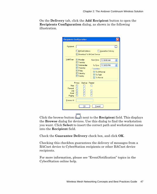
On the Delivery tab, click the Add Recipient button to open the Recipients Configuration dialog, as shown in the following illustration.
Click the browse button ( ) next to the Recipient field. This displays the Browse dialog for devices. Use this dialog to find the workstation you want. Click Select to insert the correct path and workstation name into the Recipient field.
Check the Guarantee Delivery check box, and click OK.
Checking this checkbox guarantees the delivery of messages from a BACnet device to CyberStation recipients or other BACnet device recipients.
For more information, please see “EventNotification” topics in the CyberStation online help.
Wireless Mesh Networking Concepts and Best Practices Guide 47

Chapter 2: The Andover Continuum Wireless Solution
Guidelines for Designing Your Wireless Solution
The most important challenge is determining when a wireless mesh controller network is more cost effective than a hard-wired network. The following list examines factors to consider when installing a wireless mesh network:
The most obvious reason to install a wireless mesh network is the cost of running wiring (and conduit if required) over considerable distances in new and retrofitted control projects.There is an extra cost for the electronic devices required for a wireless controller network, but the savings in labor and maintenance from not having to install and maintain wire (and potentially conduit) can more than make up for the difference in many installations.The distance between controllers can be so long that network cables cannot be easily installed.Network analyzing tools allow engineers and technicians to address, commission, and troubleshoot the wireless network from a safe, convenient location.
Wireless mesh networks incorporate a grid-like topology, allowing nodes to communicate with other nodes without being routed through a central switch point.
This eliminates centralized failure and provides a self-healing and self-organizing network. Although decisions on traffic are made locally, the system can be managed globally.
Wireless mesh networks allow the signal to “multihop” among its different nodes to circumvent obstructions as it seeks and ultimately finds its target node. These redundant communication paths provide a high level of reliability to the network. Because multiple signal paths exist, the network can adjust if some communications links are disrupted due to changes in the environment, such as the movement of people or placement of equipment.
This eliminates the need for maintenance to maintain robust communications over the network’s life as the environment changes.
48 Schneider Electric

Chapter 2: The Andover Continuum Wireless Solution
For a list of frequently asked questions about wireless controls, see Appendix A, “Frequently Asked Questions About Wireless Controls and Do’s and Don’t s” on page 53.
Major Design Factors
There are many factors in planning a wireless mesh network solution. The table below presents some of the major factors.
Site Surveys
The following list presents some general guidelines for surveying a site for a wireless mesh network:
Determine existing wireless interference using a spectrum analyzer.Set the RF channel number to a clear channel if the default channel is already in use.
Factor Consideration
Distance between nodes
Reducing link distances and adding repeaters can help to prevent changes in link quality.
Transmitter power Adjusting the transmitter power of the embedded low-power radio embedded in the RF device can improve link quality.
Proximity to other wireless devices
Environmental RF “noise” produced by powerful motors, cell phones, microwaves, wireless LANs, and other devices can make network traffic unreliable.
Obstacles to RF transmission
Metal surfaces such as water pipes and ductwork can scatter RF signals. Wireless signals may not penetrate certain materials in walls and ceilings, such as reinforced concrete. Even human bodies, which contain mostly water, might become obstacles.
Time of day and activity patterns
Industrial areas are dynamic environments where obstructions are constantly changing. For example, the movement of people, furniture, machinery, cabinets, and such create a challenge to RF signal propagation.
Power requirements Most controllers are AC-line powered because they are primarily mounted adjacent to power-hungry actuators. While wireless controller networks can be more robust by using greater power resources and don’t need battery replacement, the advantages of a wireless system are sacrificed to some extent by the need for AC-line voltage.
Wireless Mesh Networking Concepts and Best Practices Guide 49

Chapter 2: The Andover Continuum Wireless Solution
Place a few non-controlling, temporary adapters/repeaters throughout the site to test connectivity through materials, across floors, and so on.Use the Wireless Maintenance Tool to evaluate the test setup.
Adapter and Repeater Placement
There are several factors to consider when you decide where to place the Wireless Adapters and repeaters in a wireless mesh network. The following list presents some recommendations.
Whether you are mounting the device on a wall or hanging it vertically from a ceiling or object, install the device with the long axis vertical for optimum performance, as shown in the following illustration.
Install the devices at a horizontal plane height where there are as few objects as possible, typically out of sight of building occupants. For example, in an office with cubicles, install the units two feet or so above the average cubicle wall height (roughly the height of occupants) or in the plenum of the building.Install the devices away from metal or water-filled objects and away from other electronic devices. These objects and devices block or diminish the wireless RF signal.
50 Schneider Electric

Chapter 2: The Andover Continuum Wireless Solution
Think in three dimensions. Use another floor, if necessary, to get around obstacles.Use stairwells to help provide a clear path between floors.Use a non-metallic weatherproof box for rooftop and outdoor applications.Test adapter/repeater locations before permanently mounting, and test connectivity before cutting over control to a wireless controller.
For more information, please see the Andover Continuum Wireless Adapter/Repeater Installation Instructions, 30-3001-887.
New Wireless Installations
For new wireless installations, the greatest cost savings occur by avoiding the cost of installing and configuring wire (and conduit) connections. Other considerations for new installations include the following:
Adapt to changes in walls, pipes, and other obstructions that continue to change during construction.Save additional time and labor because the wireless mesh network is self-configuring and self-correcting.Communicate with any controller via a wireless connection.
Replacing Older Networks
For retrofit projects, the cost savings vary. Replacement costs could be substantially higher than for new installations, especially in situations where there are:
Older building automation systems containing network cable that may be incompatible or degraded and need to be replaced to upgrade the systemNetworks needing additions and changes that were not considered in the original designFacilities that need pneumatic controllers converted to direct digital control (DDC) technology
Wireless Mesh Networking Concepts and Best Practices Guide 51
Chapter 2: The Andover Continuum Wireless Solution
Historic buildings or buildings with interiors that cannot be disturbed or penetratedAreas that are hazardous or extremely difficult to access, such as buildings with asbestos covering heating ducts or with clean rooms.
52 Schneider Electric

Appendix A Frequently Asked Questions About Wireless Controls and Do’s and Don’t s
This chapter provides answers to frequently asked questions about Wireless Controls. Also, included is a brief ‘Do’s and Don’ts’ list in order to avoid overloading or slowing down a wireless system.
Questions and Answers about Wireless ControlsDo’s and Don’ts of Wireless
Wireless Mesh Network Concepts and Best Practices Guide 53
Appendix A: Frequently Asked Questions About Wireless Controls and Do’s and Don’t s
Questions and Answers about Wireless Controls
Q: What are the main advantages of wireless controls?
A: Wireless controls reduce installation costs and permit controls to be installed in areas that would otherwise be difficult to wire. The cost of running wire is often the most expensive component of a controls installation, especially in large cities where labor costs are high and electrical codes require conduit.
Q: What obstacles are still standing in the way of a more comprehensive acceptance of wireless controls?
A: As with any new technology, the adoption rate increases as the technology is proven. A customer wants to know that wireless controls will be reliable, secure and responsive. There needs to be good methods to plan a wireless network in a building, with an understanding of how physical obstacles and building materials affect wireless networks. With this environmental knowledge, a solid wireless network can be put together by design, rather than trial and error. The technology has now reached a maturity level where these goals can be met at an attractive cost point for a wide range of applications.
54 Schneider Electric

Appendix A: Frequently Asked Questions About Wireless Controls and Do’s and Don’t s
Q: Although an argument can be made for wireless controls for just about any facility, which building types are the most ideal applications for the technology?
A: There are four types of buildings where a wireless solution is particularly attractive — city buildings, clean rooms, historical buildings, and difficult-to-wire and remote buildings. In a city, labor costs are especially high and frequently electrical codes require all cables to be run in conduit. Clean rooms need to maintain precise climate and pressure conditions, so any penetration into the production area decreases its performance. With a historic building, it is important that the historical integrity of the structure is maintained. This means, for example, that wires cannot always be run in a straight path. So, wiring a network to the next room may mean running 1000 feet of cable versus a 10 foot wireless path. Finally, trenching a network cable to a remote building or the penetration of brick, glass, or cement walls may be difficult and expensive.
Q: How should building infrastructures ideally be set up in order to accommodate the greatest adoption of wireless control technologies in the future?
A: One of the major advantages of wireless mesh technology is that an infrastructure does not have to be in place to utilize it. Each wireless mesh node contributes toward building a strong wireless network. A wireless mesh differs from wireless Ethernet, which is a point-to-multipoint network that relies on the strategic placement of access points. In the wireless mesh model, each node has multiple connection paths and knows about all its nearest neighbors. As a result, daisy chain wiring becomes a thing of the past. If one node is disconnected or the current node is blocked, the network heals itself by simply finding its next nearest neighbors and reconnecting messages via the best connection point. Since a wireless mesh does not require an infrastructure to be created, the total cost savings over wired networks is more easily realized.
Wireless Mesh Network Concepts and Best Practices Guide 55

Appendix A: Frequently Asked Questions About Wireless Controls and Do’s and Don’t s
Q: What are the latest technological advantages in wireless controls?
A: The IEEE 802.15.4 wireless standard offers a much better wireless solution for controls over WI-FI and Bluetooth. The wireless mesh networks are self-forming and they do not require an infrastructure or access points and routers, although repeaters may be used. An IEEE 802.15.4 wireless mesh network is secure with optional built-in encryption and is reliable, since it is self-healing.
Q: Have codes and standards been developing enough to keep up with the latest wireless technologies? Have any new standards recently been passed or are seriously being considered?
A: Zigbee is an emerging wireless standard that is based on the IEEE 802.15.4 wireless standard.
Q: How do you envision the world of wireless controls, 10 and 20 years down the line?
A: With time, buildings will have an ever-increasing proportion of wireless to wired controls in them. Just as an office has a combination of wireless hotspots and wired offices for Ethernet connectivity, there may also be some level of wired controls networks within a facility. Wireless controls will become common and will include peripheral devices, such as sensors (occupancy, door contacts, intrusion point, temperature, and so on).
Open protocols, such as ASHRAE’s BACnet will adopt a wireless standard as an optional field bus within the standard. With wireless communications standardized for controls it will be possible for products from multiple vendors to share a common wireless mesh network while interoperating with each other.
Between the reduced installation costs of wireless mesh control networks and the freedom of choice offered by open protocols, building owners are looking at a future where they can provide safe, comfortable, and efficient indoor environments with the minimal effort and expense.
56 Schneider Electric

Appendix A: Frequently Asked Questions About Wireless Controls and Do’s and Don’t s
Do’s and Don’ts of Wireless
The Wireless network is not as robust as a wired system. Typically a wireless network is approximately 1/3 as fast as an equivalent wired network. The Infinet wireless network treats data exchange (import/ export) differently than a wired configuration. All data exchange is done as a guaranteed delivery point to point communication similar to a BACnet Change of Value (COV) data exchange. Precautions should be taken in programming and configuring the wireless system, to avoid data bottlenecks and network overload.
Do: When you have completed using the Wireless Maintenance Tool, shut it down to avoid overloading the system with unneeded traffic.
Do: When configuring inputs, insure that the threshold is set appropriately.
Don’t: Do not leave ListViews, with several live values running, for extended periods of time. This creates unnecessary traffic that can overload the entire wireless system.
Don’t: When using graphics to poll data from the wireless network controllers, minimize the number of points in the graphic. Do not create a large graphic polling many points. Instead make several smaller graphics with fewer points so as to not overload the network.
Note: When setting the polling rate for graphics, in the Cyberstation Workstation Preferences tab, you may want to increase the Pinpoint active and inactive polling rates so that the polling does not overload the system. Also, in the CyberStation General Preferences dialog you may want to increase the Time Interval Between Requests setting to slow the graphic polling engine which will also aid in avoiding network overload during graphic polling.
Wireless Mesh Network Concepts and Best Practices Guide 57

Appendix A: Frequently Asked Questions About Wireless Controls and Do’s and Don’t s
Don’t: When exporting points to other controllers, do not create export refresh programs setting the point's attribute "Refresh" to true. This creates excessive, unnecessary network traffic.
Note: Refreshing points, for a wireless system, is not required. All traffic is sent as a guaranteed delivery from controller to controller.
58 Schneider Electric


Wireless Mesh Network Concepts and Best Practices GuideDocument Number 30-3001-912
Revision C