wireless lan radio: spectrum management best practicesfaculty.ccc.edu/mmoizuddin/cisco live...
TRANSCRIPT

© 2006, Cisco Systems, Inc. All rights reserved.Presentation_ID.scr
1
© 2008 Cisco Systems, Inc. All rights reserved. Cisco Public 1BRKAGG-301314659_05_2008_x1
Wireless LAN Radio: Spectrum Management Best Practices
© 2008 Cisco Systems, Inc. All rights reserved. Cisco Public 2BRKAGG-301314659_05_2008_x1
BRKAGG-3013

© 2006, Cisco Systems, Inc. All rights reserved.Presentation_ID.scr
2
Trouble with Bluetooth
$30 Billion HMO With over 8.5 Million Members
The ScenarioSouth Sacramento hospital IT staff had problems with theirSouth Sacramento hospital IT staff had problems with their mobile Point of Care terminals getting disconnected from the wireless networkThe network was surveyed and implemented at –65 dBmThe IT staff began planning to increase the density of their Wi-Fi infrastructure
Solution and OutcomeUsing Cisco’s Spectrum Expert, problematic Bluetooth devices were immediately identified, said devices were transmitting at 100 W/20 dB Cl 1 Bl t th
© 2008 Cisco Systems, Inc. All rights reserved. Cisco Public 3BRKAGG-301314659_05_2008_x1
100 mW/20 dBm. Class 1 Bluetooth The Bluetooth reader devices were installed on all of the wireless carts in question Once Bluetooth readers were identified as culprits, the device manufacture reprogrammed Bluetooth devices to use a lower power outputIT staff solved issue without adding capacity, which likely would have created, not solved problems
“RF matters.”
© 2008 Cisco Systems, Inc. All rights reserved. Cisco Public 4BRKAGG-301314659_05_2008_x1
Jim FlorwickCisco Systems
© 2008 Cisco Systems, Inc. All rights reserved. Cisco Public 4BRKAGG-301314659_05_2008_x1

© 2006, Cisco Systems, Inc. All rights reserved.Presentation_ID.scr
3
What We’re Going to Cover
The challenge
Wireless trendsWireless trendsEvolution of the WLAN
Deploying with spectrum in mindSite survey
Cisco Radio Resource Management—RRM
Cisco Spectrum Expert
© 2008 Cisco Systems, Inc. All rights reserved. Cisco Public 5BRKAGG-301314659_05_2008_x1
Cisco Spectrum Expert
Intelligent mitigationCHDM
RRM Dashboard
Spectrum Intelligence
The Challenge
© 2008 Cisco Systems, Inc. All rights reserved. Cisco Public 6BRKAGG-301314659_05_2008_x1

© 2006, Cisco Systems, Inc. All rights reserved.Presentation_ID.scr
4
The Dynamic Nature of Spectrum
You are breathing the physical layer
RF reflects off thingsRF reflects off things
RF is absorbed by things
It’s a shared medium (as such, not all RF is always yours)
Requirements change in response to changes in the environment—not always helpful
Yet, if implemented and maintained properly, it’s a
© 2008 Cisco Systems, Inc. All rights reserved. Cisco Public 7BRKAGG-301314659_05_2008_x1
, p p p y,technology enabler providing
Increased productivity
Creative freedom
Enhanced user experience—by putting the power of the network where the user lives and works
Mobility Refers to the Client—Not the infrastructure
Radio assets are fixed devices Clients Associate to AP
with Strongest Signal
Autonomous AP channel and power must be set in advance
Clients move about
Resource demands shift
g g
© 2008 Cisco Systems, Inc. All rights reserved. Cisco Public 8BRKAGG-301314659_05_2008_x1
with client location, and density

© 2006, Cisco Systems, Inc. All rights reserved.Presentation_ID.scr
5
Even When Well Planned, Things Change
Mission critical requires HA
Client technology refresh—additional device typesClient technology refresh—additional device types
Moves, adds, changes
New neighbors?
© 2008 Cisco Systems, Inc. All rights reserved. Cisco Public 9BRKAGG-301314659_05_2008_x1
Multiple QoS Demands
Managing multiple QoS streams
Balancing dynamic demandsBalancing dynamic demands
Changing user requirements
Video Conferencing
VoD
© 2008 Cisco Systems, Inc. All rights reserved. Cisco Public 10BRKAGG-301314659_05_2008_x1
Video and Audio Streaming
Voice

© 2006, Cisco Systems, Inc. All rights reserved.Presentation_ID.scr
6
A Series of Papers on Wi-Fi Interference Concluded…http://www.cisco.com/en/US/products/ps9393/prod_white_papers_list.html
Does Non–Wi-Fi Interference Matter?
Normal Range
Reduced Range
Degraded Range
VideoVoiceData
© 2008 Cisco Systems, Inc. All rights reserved. Cisco Public 11BRKAGG-301314659_05_2008_x1
Reduced Coveragefrom 20% to 80% Reduced Call Quality Most Video Rated “Unwatchable”
..That Dramatic Loss in Quality of Mobility Services Will Result When Wi-Fi Encounters Interference
The Problem: Wi-Fi Competes for Spectrum
Bluetooth
802.11FHOlder microwave linksGame controllersWireless headphonesWireless videoMobile and fixed alarm systems
RadarMicrowave Ovens
© 2008 Cisco Systems, Inc. All rights reserved. Cisco Public 12BRKAGG-301314659_05_2008_x1
Causes Issues That Slow Down Acceptance, Erodes Customer Confidence
Other Wi-Fi Networks 2.4/5 GHz Cordless Phones
yMotion sensorsFluorescent lightsA pinball machine (really)

© 2006, Cisco Systems, Inc. All rights reserved.Presentation_ID.scr
7
Wireless Trends
© 2008 Cisco Systems, Inc. All rights reserved. Cisco Public 13BRKAGG-301314659_05_2008_x1
Evolution of WLAN
Wireless initially for casual data—user convenience
Customer expectations set for best effort serviceCustomer expectations set for best effort service
Maturing mobility applications
Enterprise class—mission-critical architectures
Enterprise class—end-to-end security
Productivity gains realized—customer expectations increased
© 2008 Cisco Systems, Inc. All rights reserved. Cisco Public 14BRKAGG-301314659_05_2008_x1
Wireless access is now edge access
Multiple wireless devices—multiple spectrums
Spectrum Is a Mission-Critical Resource $$$$$

© 2006, Cisco Systems, Inc. All rights reserved.Presentation_ID.scr
8
Deploying with Spectrum in Mind
© 2008 Cisco Systems, Inc. All rights reserved. Cisco Public 15BRKAGG-301314659_05_2008_x1
Deploying with Spectrum in Mind
Role of site survey is as important as ever—but has evolved
Understanding the existing spectrumUnderstanding the existing spectrum
Focus should be on fixed infrastructureAP placement
Density is important
Protocols supported
Rates supported
© 2008 Cisco Systems, Inc. All rights reserved. Cisco Public 16BRKAGG-301314659_05_2008_x1
Interference sources
Mitigating issues
Planning tools
Designing for Sustainable Spectrum Management

© 2006, Cisco Systems, Inc. All rights reserved.Presentation_ID.scr
9
What’s Using the Spectrum Now?
Spectrum is finite
Duty cycle orDuty cycle or utilization of non–Wi-Fi devices (noise) matters
© 2008 Cisco Systems, Inc. All rights reserved. Cisco Public 17BRKAGG-301314659_05_2008_x1
What’s Using the Spectrum Now?
Identify Interference, Hits to SNRSNR (Signal to Noise Ratio) is a ratio
To improve SNRIncrease signal
Or Reduce Noise
© 2008 Cisco Systems, Inc. All rights reserved. Cisco Public 18BRKAGG-301314659_05_2008_x1

© 2006, Cisco Systems, Inc. All rights reserved.Presentation_ID.scr
10
AP Placement—Evaluate Problem Areas
© 2008 Cisco Systems, Inc. All rights reserved. Cisco Public 19BRKAGG-301314659_05_2008_x1
AP Placement—Evaluate Problem Areas
Si lObject in Signal Path
Plasterboard wall
Glass wall with metal frame
Cinder block wall
Office window
3 dB
6 dB
4 dB
3 dB
Signal Attenuation
© 2008 Cisco Systems, Inc. All rights reserved. Cisco Public 20BRKAGG-301314659_05_2008_x1
Metal door
Metal door in brick wall
Phone and Head position
6 dB
12 dB
6 dB

© 2006, Cisco Systems, Inc. All rights reserved.Presentation_ID.scr
11
Access Point Placement Guidelines
How many APs do I needDetermined by the site survey
© 2008 Cisco Systems, Inc. All rights reserved. Cisco Public 21BRKAGG-301314659_05_2008_x1
Determined by the site survey
Planning mode in WCS can assist in determining adequate coverage density
Place where clients will be locatedIn a meeting room VSAN adjacent hallway
In a central location that can cover multiple walled offices
Not in a wiring closet
Coverage Density
© 2008 Cisco Systems, Inc. All rights reserved. Cisco Public 22BRKAGG-301314659_05_2008_x1

© 2006, Cisco Systems, Inc. All rights reserved.Presentation_ID.scr
12
AP Placement Considerations—Multipath
Highly reflective environments
Multipath distortion/fade is a consideration
802.11b most prone
802.11g/a better
Things that reflect RF
© 2008 Cisco Systems, Inc. All rights reserved. Cisco Public 23BRKAGG-301314659_05_2008_x1
Things that reflect RFIrregular metal surfaces
Large glass enclosures/walls
Lots of polished stone
Minimize the Impact of Multipath
Temptation is to mount on beams or ceiling rails
This reflects transmitted as well as received packets
Dramatic reduction in SNR due to high-strength, multipath signals
© 2008 Cisco Systems, Inc. All rights reserved. Cisco Public 24BRKAGG-301314659_05_2008_x1
Minimize Reflections When Choosing Locations

© 2006, Cisco Systems, Inc. All rights reserved.Presentation_ID.scr
13
Planning Tools—Cisco Spectrum Expert
© 2008 Cisco Systems, Inc. All rights reserved. Cisco Public 25BRKAGG-301314659_05_2008_x1
Planning Tools—Cisco Spectrum Expert
© 2008 Cisco Systems, Inc. All rights reserved. Cisco Public 26BRKAGG-301314659_05_2008_x1

© 2006, Cisco Systems, Inc. All rights reserved.Presentation_ID.scr
14
Planning Tools—Cisco Spectrum Expert
© 2008 Cisco Systems, Inc. All rights reserved. Cisco Public 27BRKAGG-301314659_05_2008_x1
Example: Microwave
Duty Cycle Higher in Part of BandLoud Moving
Signal Seen in Max and Max
Hold
© 2008 Cisco Systems, Inc. All rights reserved. Cisco Public 28BRKAGG-301314659_05_2008_x1
Drifts in Frequency

© 2006, Cisco Systems, Inc. All rights reserved.Presentation_ID.scr
15
Example: Microwave
© 2008 Cisco Systems, Inc. All rights reserved. Cisco Public 29BRKAGG-301314659_05_2008_x1
Example: Microwave
1
2
3
4
5
6
© 2008 Cisco Systems, Inc. All rights reserved. Cisco Public 30BRKAGG-301314659_05_2008_x1
–11dBm–114dBm
6
7

© 2006, Cisco Systems, Inc. All rights reserved.Presentation_ID.scr
16
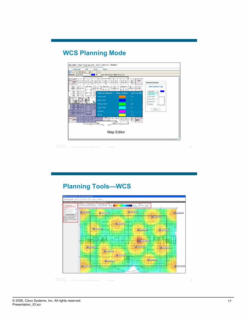
Planning Tools—WCS Planning Mode
Allows Comprehensive
Selection of AP and Antenna Type as Well as Several
Deployment Options
Allows the Addition of Obstacles
(Attenuations) to the Map, Default
Values Are Editable
Add in Existing APs from a
Deployed Floor
© 2008 Cisco Systems, Inc. All rights reserved. Cisco Public 31BRKAGG-301314659_05_2008_x1
Options Values Are EditableGenerates a
Comprehensive Proposal Including Assumptions, Heat
and Rate Maps
WCS Planning Mode—AP SelectionAP TypeAntenna TypeProtocol Selection Including NgDesired Throughput Services Allows for
Selection of Data—Margins Adjustable in 3 Db Increments—Aggressive, Safe, Very Safe
Voice SettingsAggressive = Minimum [–78 dBm]Safe = Medium [–75 dBm]Very Safe = Maximum [(–72 dBm]7920_enabled = [(–72 dBm] (802 11a); 67 dBm (802 11b/g)]
Optimized Placement for Location with/
© 2008 Cisco Systems, Inc. All rights reserved. Cisco Public 32BRKAGG-301314659_05_2008_x1
(802.11a); -67 dBm (802.11b/g)]
Demand Allows for Calculations Based on Total Users, as Well as Users per AP
Override to Bias the Coverage per AP
for Location with/ Without MMAP
© 2006, Cisco Systems, Inc. All rights reserved.Presentation_ID.scr
17
WCS Planning Mode
1 Cubicle
4 Light door
15 Heavy door
2 Light wall
13 Thick wall
Loss (in dB) Color coding Type of obstacle
© 2008 Cisco Systems, Inc. All rights reserved. Cisco Public 33BRKAGG-301314659_05_2008_x1
Map Editor
1.5 Glass
Planning Tools—WCS
© 2008 Cisco Systems, Inc. All rights reserved. Cisco Public 34BRKAGG-301314659_05_2008_x1

© 2006, Cisco Systems, Inc. All rights reserved.Presentation_ID.scr
18
Deploying with RRM in Mind
© 2008 Cisco Systems, Inc. All rights reserved. Cisco Public 35BRKAGG-301314659_05_2008_x1
RRM—Radio Resource Management
What are RRM’s objectives?To dynamically balance the infrastructure and mitigate changesTo dynamically balance the infrastructure and mitigate changes
Monitor and maintain coverage for all clients
Manage Spectrum Efficiency so as to provide the optimal throughput under changing conditions
What RRM does not doSubstitute for a site survey
© 2008 Cisco Systems, Inc. All rights reserved. Cisco Public 36BRKAGG-301314659_05_2008_x1
Correct an incorrectly architected network
Manufacture spectrum

© 2006, Cisco Systems, Inc. All rights reserved.Presentation_ID.scr
19
RRM Monitors the RF Group
Continuously monitors dynamic changes in environment
Collection of statistics and metrics used by DCA, DPC, and CHDM
Provides assessment of the overall “health” of the network
Stats/metrics include:Noise (e.g., radar, Bluetooth devices, microwave ovens)
© 2008 Cisco Systems, Inc. All rights reserved. Cisco Public 37BRKAGG-301314659_05_2008_x1
Interference (802.11—both our WLAN and rogue APs)
Coverage
Load
Info on neighboring APs/radios
How Does RRM Do This?
DCA—Dynamic Channel AssignmentEach AP radio gets a transmit channel assigned to itchannel assigned to itChanges in “air quality” are monitored, AP channel assignment changed when deemed appropriate (based on DCA cost function)
DPC—Dynamic Power ControlTx Power assignment based on radio to radio pathlossDPC is in charge of reducing Tx on some APs—but may also increase Tx by defaulting back to
© 2008 Cisco Systems, Inc. All rights reserved. Cisco Public 38BRKAGG-301314659_05_2008_x1
y y gpower level higher than the current Tx level
CHDM—Coverage Hole Detection and Mitigation
Detecting clients in coverage holesDeciding on Tx adjustment (typically Tx increase) on certain APs based on (in)adequacy of estimated downlink client coverage

© 2006, Cisco Systems, Inc. All rights reserved.Presentation_ID.scr
20
RF Group Controllers Elect an RF Group Leader That Analyses RF Data and Neighbor Relationships to Make More Intelligent Decisions About Optimizing the RF Environment for the System
About RF Groups
Wireless Controller ARF Group = <asciii string>
Wireless Controller BRF Group = <ascii string>
Environment for the System
© 2008 Cisco Systems, Inc. All rights reserved. Cisco Public 39BRKAGG-301314659_05_2008_x1
< -80dbm
Neighbor Messages Are Sent At Full Power, Containing Information About the AP Seen, and Authenticated via a MIC Based on the RF Group Name
IF APs on Different Controllers Hear Neighbor Messages from APs in the Same RF Group at –80 Dbm or Greater They Will Group in an RF Subgroup, Channel, and Power Then Compute as a Group
LogicalRF sub-group (a)
RF Grouping and RF Domains
Multiple “RF subgroups” can exist within a single RF GroupRRM is calculated on a per RF group basis
LogicalRF sub-group (b)
Logical RF sub-group (c)Logical RF sub-group (b)
RFGroup 1RFGroup 1
RFGroup
RRM is calculated on a per RF group basisRF subgroups can be intercontroller or intracontrollerMultiple RF subgroups may be formed even when controllers share an RF Group name
RF groups/subgroups apply per PHY type
© 2008 Cisco Systems, Inc. All rights reserved. Cisco Public 40BRKAGG-301314659_05_2008_x1
g g p ( )g g p ( )
Logical RF sub-group (d)Logical RF sub-group (a)
Logical RF sub-group (e)
LogicalRF sub-group (b)
LogicalRF sub-group (a)
LogicalRF sub-group (c)
RFGroup

© 2006, Cisco Systems, Inc. All rights reserved.Presentation_ID.scr
21
New Access Point Causes Co-Channel Interference
System Optimizes Channel Assignments to Decrease Interference
RRM—DCA—Dynamic Channel Assignment
RF Channel “6”RF Channel “1”
© 2008 Cisco Systems, Inc. All rights reserved. Cisco Public 41BRKAGG-301314659_05_2008_x1
RF Channel “11”
What ItDoes
Ensures that available RF spectrum is utilized well across frequencies/channels
Best network throughput is achieved without sacrificing stability or AP availability to clients
DCA in a Nutshell
Who calculates DCAIt runs on the RF Group Leader WLCLeader WLC
Decisions on channel assignment change made on a per AP, per radio basis
DCA manages channel assignments to each AP
Assigns channels to radios
Changes the existing assignment
© 2008 Cisco Systems, Inc. All rights reserved. Cisco Public 42BRKAGG-301314659_05_2008_x1
Changes the existing assignment on some radios, if appropriate
What criterion is evaluated:RSSI-based Cost Function that captures overall interference (including non-802.11 noise) on a channel
© 2006, Cisco Systems, Inc. All rights reserved.Presentation_ID.scr
22
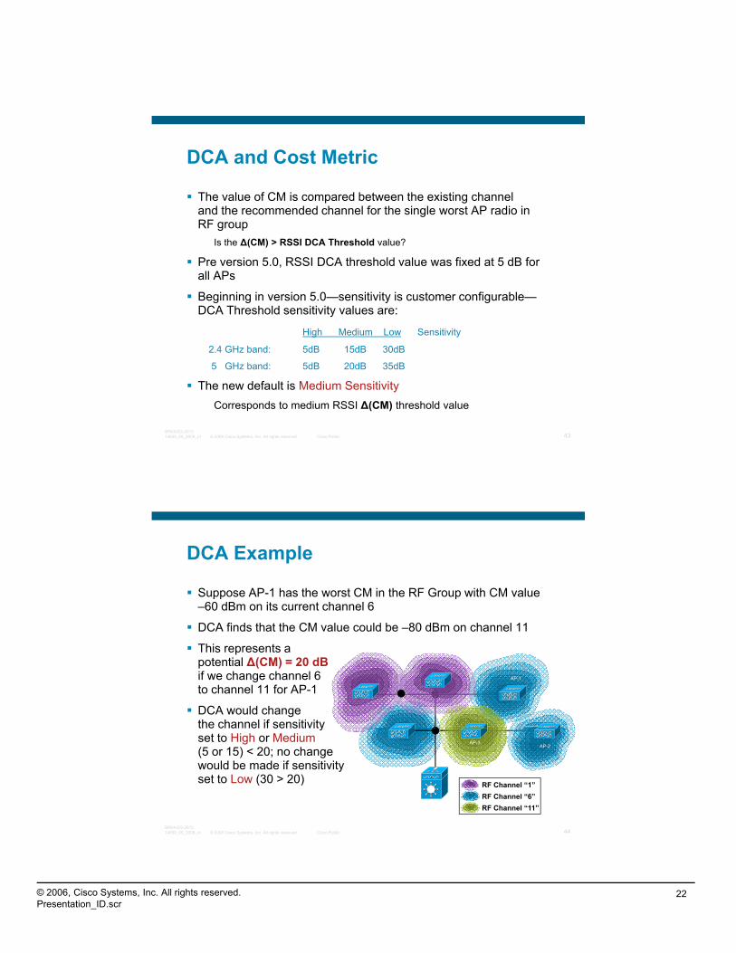
DCA and Cost Metric
The value of CM is compared between the existing channel and the recommended channel for the single worst AP radio in RF groupRF group
Is the Δ(CM) > RSSI DCA Threshold value?
Pre version 5.0, RSSI DCA threshold value was fixed at 5 dB for all APs
Beginning in version 5.0—sensitivity is customer configurable—DCA Threshold sensitivity values are:
High Medium Low Sensitivity
© 2008 Cisco Systems, Inc. All rights reserved. Cisco Public 43BRKAGG-301314659_05_2008_x1
High Medium Low Sensitivity
2.4 GHz band: 5dB 15dB 30dB
5 GHz band: 5dB 20dB 35dB
The new default is Medium SensitivityCorresponds to medium RSSI Δ(CM) threshold value
DCA Example
Suppose AP-1 has the worst CM in the RF Group with CM value –60 dBm on its current channel 6
DCA finds that the CM value could be –80 dBm on channel 11
This represents a potential Δ(CM) = 20 dBif we change channel 6 to channel 11 for AP-1
DCA would change the channel if sensitivity
AP-1
© 2008 Cisco Systems, Inc. All rights reserved. Cisco Public 44BRKAGG-301314659_05_2008_x1
yset to High or Medium(5 or 15) < 20; no change would be made if sensitivity set to Low (30 > 20)
RF Channel “6”RF Channel “1”
RF Channel “11”
AP-2AP-3

© 2006, Cisco Systems, Inc. All rights reserved.Presentation_ID.scr
23
RRM Support for 40 MHz
40 MHz channels can be configured automatically using Cisco WCS or Controller only
20 MHz
20 MHz40- HzGained
Space
Cisco WCS or Controller—only applies to 5 GHz radios
40 MHz channels can still be statically configured on 2.4 GHz radios
Improves 802.11n network performance
40 MHz = Two aggregated 20 MHz channels
Takes advantage of the reserved channel space through bonding to gain more than double the data rate of two 20 MHz channels
© 2008 Cisco Systems, Inc. All rights reserved. Cisco Public 45BRKAGG-301314659_05_2008_x1
Available 40 MHz Channels
No DFS Support
DFS Support
4 11
2
1 3 5 7 9 11
4 6 8 10
5 GHz 40 MHz Channels
Cisco Aironet® 1250
DFS and Available Bandwidth
Scheduled DCA
Prior to release 5.1, DCA had a fixed run interval at 1 in 10; it ran once every 10 minutes
With the release 5.1 DCA is customer scheduled using two valuesAnchor Time—the time that DCA will first run 0100–2400
Interval–the interval between DCA runs–1–24 hours
Minimum interval is 1 hour
Scheduled DCA is off by default
Channel Change is the most disruptive change
© 2008 Cisco Systems, Inc. All rights reserved. Cisco Public 46BRKAGG-301314659_05_2008_x1
The AP is temporarily unavailable
Some older Clients can become confused—and not find new channel
Channel changes should be done much more conservatively that TX power changes in DPC—less is more
Only a promise of considerable improvement should warrant a channel change

© 2006, Cisco Systems, Inc. All rights reserved.Presentation_ID.scr
24
DCA and Spectrum 802.11 b/g
© 2008 Cisco Systems, Inc. All rights reserved. Cisco Public 47BRKAGG-301314659_05_2008_x1
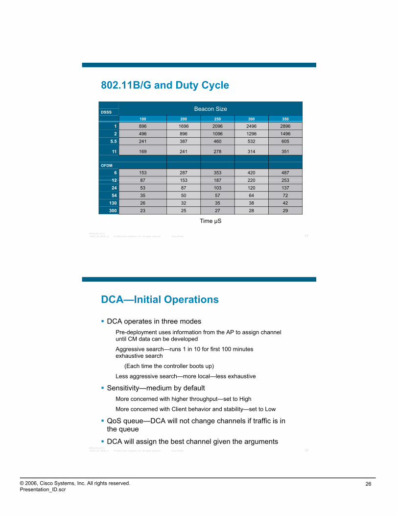
802.11B/G and Duty Cycle
APs per Channel
© 2008 Cisco Systems, Inc. All rights reserved. Cisco Public 48BRKAGG-301314659_05_2008_x1
Duty Cycle vs. Time

© 2006, Cisco Systems, Inc. All rights reserved.Presentation_ID.scr
25
Channel Utilization—What Made the Difference?
What Made This Dramatic
Change?
Before
© 2008 Cisco Systems, Inc. All rights reserved. Cisco Public 49BRKAGG-301314659_05_2008_x1
5% After
Noise, Interference, and Utilization via WLC
RX Utilization 36
TX Utilization 7
Channel Utilization 96
© 2008 Cisco Systems, Inc. All rights reserved. Cisco Public 50BRKAGG-301314659_05_2008_x1
© 2006, Cisco Systems, Inc. All rights reserved.Presentation_ID.scr
26
802.11B/G and Duty Cycle
Beacon SizeDSSS
100 200 250 300 350
1 896 1696 2096 2496 28962 496 896 1096 1296 1496
5.5 241 387 460 532 605
11 169 241 278 314 351
OFDM
6 153 287 353 420 48712 87 153 187 220 253
© 2008 Cisco Systems, Inc. All rights reserved. Cisco Public 51BRKAGG-301314659_05_2008_x1
12 87 153 187 220 25324 53 87 103 120 13754 35 50 57 64 72
130 26 32 35 38 42300 23 25 27 28 29
Time µS
DCA—Initial Operations
DCA operates in three modesPre-deployment uses information from the AP to assign channel until CM data can be developed
Aggressive search—runs 1 in 10 for first 100 minutes exhaustive search
(Each time the controller boots up)
Less aggressive search—more local—less exhaustive
Sensitivity—medium by default
© 2008 Cisco Systems, Inc. All rights reserved. Cisco Public 52BRKAGG-301314659_05_2008_x1
More concerned with higher throughput—set to High
More concerned with Client behavior and stability—set to Low
QoS queue—DCA will not change channels if traffic is in the queue
DCA will assign the best channel given the arguments

© 2006, Cisco Systems, Inc. All rights reserved.Presentation_ID.scr
27
Power Not Optimized—RF Signal Bleeds—Causes Interference
Decreased Power Limits Interference and Improves Application Performance
RRM—DCA—Dynamic Power Control
RF Channel “6”RF Channel “1”
© 2008 Cisco Systems, Inc. All rights reserved. Cisco Public 53BRKAGG-301314659_05_2008_x1
What ItDoes
TX power assignment based on radio to radio pathloss
DPC cf. in charge of reducing Tx on some APs—but it can also increase Tx by defaulting back to power level higher than the current Tx level (under appropriate circumstances)
RF Channel “11”
DPC in a Nutshell
Who calculates DPCIt runs on the RF Group Leader WLC
Decisions on TX power assignment change made on a per AP, per radio basis
DPC viewed as a two-stage processDetermining the ideal Tx for a radio given neighboring AP info
Deciding if making the change from Tx_current to Tx_ideal is actually worth one’s while
© 2008 Cisco Systems, Inc. All rights reserved. Cisco Public 54BRKAGG-301314659_05_2008_x1
Determining Tx_ideal for a radioTx_ideal = Tx_max + (DPC_Threshold – RSSI_3rd)
Comparing the tentative improvement vs. the hysteresisIf change from Tx_current to Tx_ideal is small, since Tx changes can be disruptive, it may be better to leave AP’s Tx as is

© 2006, Cisco Systems, Inc. All rights reserved.Presentation_ID.scr
28
DPC—The Neighbor List
APs send Neighbor Messages at the highest TX power and lowest data rate for each supported protocol (802.11 a/b/g) and served channel at default 60 second intervalsand served channel at default 60-second intervalsWhen APs receive Neighbor Messages the frames are forwarded to the WLC to determine if the message is from the same RF group as the receiving APAn AP that sends either undecipherable Neighbor messages (indicating that a foreign RF group name is being used) or does not send Neighbor Messages, is determined to be a
© 2008 Cisco Systems, Inc. All rights reserved. Cisco Public 55BRKAGG-301314659_05_2008_x1
rogue AP A neighbor list is formed for each AP in an RF subgroupAn RF subgroup is a group of APs that can hear each other within an RF GroupNeighbor list is pruned at 60-minute intervals
Neighbor Message Format
Field Name Description
Radio Identifier APs with Multiple Radios Use This to Identify Which Radio Is Being Used to Transmit Neighbor Messages
Group ID A Counter and MAC Address of the WLC
WLC IP Address Management IP Address of the RF Group Leader
AP’s Channel Native Channel on Which the AP Services Clients
N i hb M Ch l Channel on Which the Neighbor Packet Is
© 2008 Cisco Systems, Inc. All rights reserved. Cisco Public 56BRKAGG-301314659_05_2008_x1
Neighbor Message Channel gTransmitted
Power Not Currently Used
Antenna Not Currently Used
© 2006, Cisco Systems, Inc. All rights reserved.Presentation_ID.scr
29
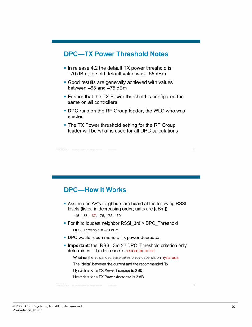
DPC—TX Power Threshold Notes
In release 4.2 the default TX power threshold is –70 dBm, the old default value was –65 dBm
Good results are generally achieved with values between –68 and –75 dBm
Ensure that the TX Power threshold is configured the same on all controllers
DPC runs on the RF Group leader, the WLC who was
© 2008 Cisco Systems, Inc. All rights reserved. Cisco Public 57BRKAGG-301314659_05_2008_x1
elected
The TX Power threshold setting for the RF Group leader will be what is used for all DPC calculations
DPC—How It Works
Assume an AP’s neighbors are heard at the following RSSI levels (listed in decreasing order; units are [dBm])
–45, –55, –67, –75, –78, –80
For third loudest neighbor RSSI_3rd > DPC_ThresholdDPC_Threshold = –70 dBm
DPC would recommend a Tx power decrease
Important: the RSSI_3rd >? DPC_Threshold criterion only determines if Tx decrease is recommended
© 2008 Cisco Systems, Inc. All rights reserved. Cisco Public 58BRKAGG-301314659_05_2008_x1
determines if Tx decrease is recommendedWhether the actual decrease takes place depends on hysteresis
The “delta” between the current and the recommended Tx
Hysterisis for a TX Power increase is 6 dB
Hysterisis for a TX Power decrease is 3 dB

© 2006, Cisco Systems, Inc. All rights reserved.Presentation_ID.scr
30
DPC—How It Works
There are two main TX power scenarios that can trigger an increase
There is no third neighbor
TPC Equation evaluates the recommended Tx to be in between Tx_max and Tx_current (rather than lower than TX_current)
Power decreases take place gradually –1 power level at a time (3 dB)
TPC i h i di t l
© 2008 Cisco Systems, Inc. All rights reserved. Cisco Public 59BRKAGG-301314659_05_2008_x1
TPC power increases happen immediately
DPC—Why Is It the Third Neighbor?
2.4 GHz Uses Third Neighbor
© 2008 Cisco Systems, Inc. All rights reserved. Cisco Public 60BRKAGG-301314659_05_2008_x1
5 GHz Uses 8th Neighbor

© 2006, Cisco Systems, Inc. All rights reserved.Presentation_ID.scr
31
“RF Matters”
© 2008 Cisco Systems, Inc. All rights reserved. Cisco Public 61BRKAGG-301314659_05_2008_x1
Intelligent Mitigation
© 2008 Cisco Systems, Inc. All rights reserved. Cisco Public 62BRKAGG-301314659_05_2008_x1

© 2006, Cisco Systems, Inc. All rights reserved.Presentation_ID.scr
32
Radio Resource ManagementCoverage Hole Detection and Mitigation
Access Point FailureCoverage Hole Detected and Filled
Normal Operation
© 2008 Cisco Systems, Inc. All rights reserved. Cisco Public 63BRKAGG-301314659_05_2008_x1
What ItDoes
No single point of failure
Automated network failover decreases support and downtime costs
Wireless network reliability approaches wired
RRM—CHDM
Runs on every controller independently from the RF Group Leader
Detection—WLCDetermines for each client of an AP if that client is in a CH (coverage hole)
Keeps the count of how many of a given AP’s clients are in a coverage hole
Mitigation is dependant upon
© 2008 Cisco Systems, Inc. All rights reserved. Cisco Public 64BRKAGG-301314659_05_2008_x1
CH detection—and NumFailedClients threshold
Decides if an AP’s TX needs to be increased
Decides on the rate/amount of increase
Operations Are Completely Independent of DPC, but Will Affect DPC and DCA

© 2006, Cisco Systems, Inc. All rights reserved.Presentation_ID.scr
33
How does WLC Detect a CH?
Based on SNR calculated from the APCan’t always know what the clients experience actually isCan t always know what the clients experience actually is
Not all detected holes are legitimateMobile clients moving out of coverage range
Sticky, poor roaming logic of a client
Not all legitimate coverage holes are fixable with TX increase
© 2008 Cisco Systems, Inc. All rights reserved. Cisco Public 65BRKAGG-301314659_05_2008_x1
increaseAnd, not all that are should be
Think SystemwideOperations Are Completely Independent of DPC, but Will Affect DCA and DPC
CHDM Improvements—4.1.185
New Feature Expected/Desired System Behavior
NumClientsThresh: Threshold in Terms of the Number of Clients in
CH Required to Trigger the Mitigation Part of CHDM
(i.e., Whether the AP Should Increase Its Tx)
Tx Increase Is Triggered if and Only if NumFailedClients ≥
NumClientsThresh
TxIncreaseLimit: Knob That Th T I i Si l
© 2008 Cisco Systems, Inc. All rights reserved. Cisco Public 66BRKAGG-301314659_05_2008_x1
TxIncreaseLimit: Knob That Controls the Amount of an APs Transmit Power Increase in a
Single Iteration Of CHDM
The Tx Increase in a Single Iteration Should Not Exceed
TxIncreaseLimit

© 2006, Cisco Systems, Inc. All rights reserved.Presentation_ID.scr
34
Important Improvements Version 5.0
Improved load metricsMassive improvements in accuracy of estimatesMassive improvements in accuracy of estimates
Impact to code base minor
Enhanced Coverage Hole DetectionVery important feature—impacts much of RRM
Main functional improvement: detecting clients that are roaming poorly
© 2008 Cisco Systems, Inc. All rights reserved. Cisco Public 67BRKAGG-301314659_05_2008_x1
Note: Some of the components were not possible to be implemented in the Edgewood timeframe
Improvements in Load Metrics
Previous approximations of load metrics were poorSince the metrics were done at the host layer, RRM based on those
i l k d d i f l l i imetrics lacked a good picture of low layer activity
New estimates are much better since they are based upon PHY and Low Layer MAC measurements
Rx Load% of time the channel is utilized by traffic directed to the radio
(Of an AP in this case) i e Fraction of time spent listening to traffic
© 2008 Cisco Systems, Inc. All rights reserved. Cisco Public 68BRKAGG-301314659_05_2008_x1
i.e., Fraction of time spent listening to trafficTx Load
% of time the channel is utilized by traffic sent by the radioi.e., fraction of time spent sending traffic
CCA Load% of time the channel is busy due to any kind of traffic
© 2006, Cisco Systems, Inc. All rights reserved.Presentation_ID.scr
35
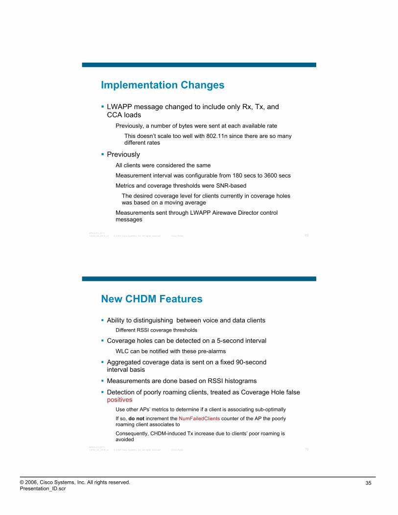
Implementation Changes
LWAPP message changed to include only Rx, Tx, and CCA loads
Previously, a number of bytes were sent at each available rate
This doesn’t scale too well with 802.11n since there are so many different rates
PreviouslyAll clients were considered the same
Measurement interval was configurable from 180 secs to 3600 secs
© 2008 Cisco Systems, Inc. All rights reserved. Cisco Public 69BRKAGG-301314659_05_2008_x1
Metrics and coverage thresholds were SNR-based
The desired coverage level for clients currently in coverage holes was based on a moving average
Measurements sent through LWAPP Airewave Director control messages
New CHDM Features
Ability to distinguishing between voice and data clientsDifferent RSSI coverage thresholds
Coverage holes can be detected on a 5-second intervalWLC can be notified with these pre-alarms
Aggregated coverage data is sent on a fixed 90-second interval basis
Measurements are done based on RSSI histograms
Detection of poorly roaming clients treated as Coverage Hole false
© 2008 Cisco Systems, Inc. All rights reserved. Cisco Public 70BRKAGG-301314659_05_2008_x1
Detection of poorly roaming clients, treated as Coverage Hole false positives
Use other APs’ metrics to determine if a client is associating sub-optimally
If so, do not increment the NumFailedClients counter of the AP the poorly roaming client associates to
Consequently, CHDM-induced Tx increase due to clients’ poor roaming is avoided

© 2006, Cisco Systems, Inc. All rights reserved.Presentation_ID.scr
36
Cisco WCS RRM Dashboard
FeaturesAPs with mostAPs with most channel changes
APs running at maximum power
APs with coverage hole events
Top channel
© 2008 Cisco Systems, Inc. All rights reserved. Cisco Public 71BRKAGG-301314659_05_2008_x1
change reasons
RRM related configuration mismatches across all controllers in RF Group
RRM Dashboard
ObjectiveIdentify trouble spotsIdentify trouble spots
Simplify troubleshooting of RRM-related events
ContentAPs with most channel changes
APs running at maximum power
APs with coverage hole events
© 2008 Cisco Systems, Inc. All rights reserved. Cisco Public 72BRKAGG-301314659_05_2008_x1
APs with coverage hole events
Top channel change reasons
RRM-related configuration mismatches across all controllers in RF Group

© 2006, Cisco Systems, Inc. All rights reserved.Presentation_ID.scr
37
RRM Dashboard—Main Screen (1 of 3)Visibility into RF Groups
© 2008 Cisco Systems, Inc. All rights reserved. Cisco Public 73BRKAGG-301314659_05_2008_x1
Quick Snapshot of the Network, and the Reasons Behind a Certain Event, Such as, Channel Changes
RRM Dashboard—Main Screen (2 of 3)Go Right into the Details of What
Configuration Mismatches Have Been Detected Across WLCs in an RF Group
Get an Instant Look into Potential Problems with APs Running “Hotter” Than Usual
© 2008 Cisco Systems, Inc. All rights reserved. Cisco Public 74BRKAGG-301314659_05_2008_x1

© 2006, Cisco Systems, Inc. All rights reserved.Presentation_ID.scr
38
RRM Dashboard—APs at Max Power
Notice the “Sort Order” in Each of These Screens to Understand How
Items on Each Page Are SortedItems on Each Page Are Sorted
© 2008 Cisco Systems, Inc. All rights reserved. Cisco Public 75BRKAGG-301314659_05_2008_x1
Excludes APs That Are Down, But Includes APs That Have Statically
Been Assigned With Tx Power Level 1
RRM Dashboard—APs with Most Channel Changes
“S t O d ”“Sort Order” with Multisort
© 2008 Cisco Systems, Inc. All rights reserved. Cisco Public 76BRKAGG-301314659_05_2008_x1

© 2006, Cisco Systems, Inc. All rights reserved.Presentation_ID.scr
39
RRM Dashboard—RF Group Members’ Configuration Mismatch
© 2008 Cisco Systems, Inc. All rights reserved. Cisco Public 77BRKAGG-301314659_05_2008_x1
Quickly Identify the (Potential And Unintentional) Mismatch of RRM-Related Configuration Across
All Controllers in a RF Group
RRM Dashboard—APs Reporting Coverage Holes
Perhaps There’s Not Enough Coverage in These Areas if the Same
AP Is Seen Here Often, or ReportsAP Is Seen Here Often, or Reports Multiple Events in a Short Span
© 2008 Cisco Systems, Inc. All rights reserved. Cisco Public 78BRKAGG-301314659_05_2008_x1
© 2006, Cisco Systems, Inc. All rights reserved.Presentation_ID.scr
40
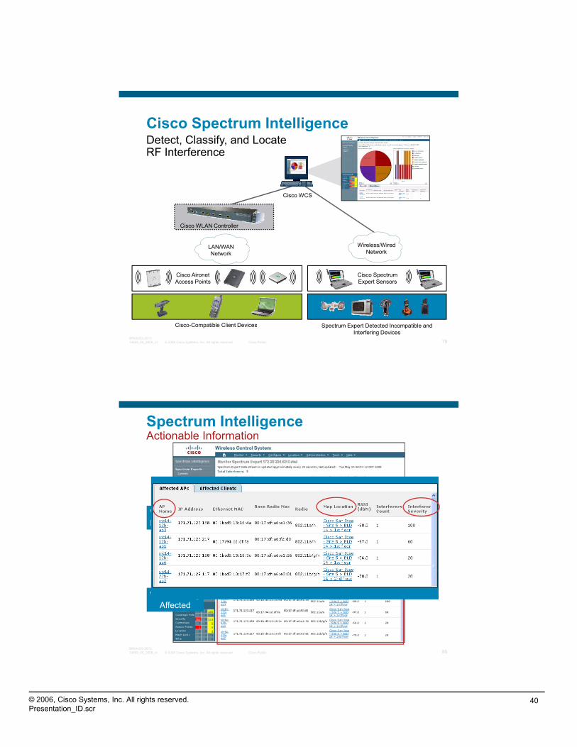
Cisco Spectrum IntelligenceDetect, Classify, and Locate RF Interference
Cisco WCS
Cisco WLAN Controller
LAN/WANNetwork
Wireless/WiredNetwork
© 2008 Cisco Systems, Inc. All rights reserved. Cisco Public 79BRKAGG-301314659_05_2008_x1
Cisco AironetAccess Points
Cisco-Compatible Client Devices Spectrum Expert Detected Incompatible and Interfering Devices
Cisco Spectrum Expert Sensors
Spectrum Intelligence Actionable Information
What’s UsingMy Spectrum
© 2008 Cisco Systems, Inc. All rights reserved. Cisco Public 80BRKAGG-301314659_05_2008_x1
What’s BeingAffected
© 2006, Cisco Systems, Inc. All rights reserved.Presentation_ID.scr
41
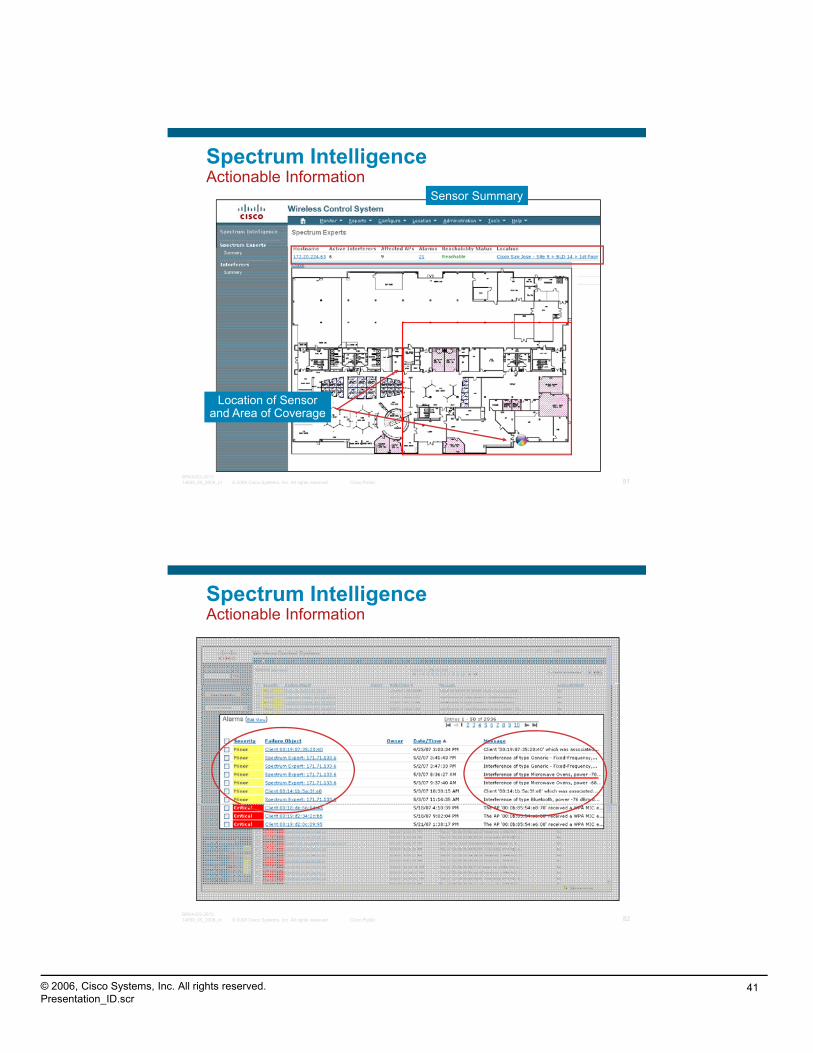
Sensor Summary
Spectrum Intelligence Actionable Information
© 2008 Cisco Systems, Inc. All rights reserved. Cisco Public 81BRKAGG-301314659_05_2008_x1
Location of Sensorand Area of Coverage
Spectrum Intelligence Actionable Information
© 2008 Cisco Systems, Inc. All rights reserved. Cisco Public 82BRKAGG-301314659_05_2008_x1

© 2006, Cisco Systems, Inc. All rights reserved.Presentation_ID.scr
42
Spectrum Intelligence Actionable Information
© 2008 Cisco Systems, Inc. All rights reserved. Cisco Public 83BRKAGG-301314659_05_2008_x1
Spectrum Intelligence Actionable Information
© 2008 Cisco Systems, Inc. All rights reserved. Cisco Public 84BRKAGG-301314659_05_2008_x1

© 2006, Cisco Systems, Inc. All rights reserved.Presentation_ID.scr
43
WCS 4.2 Spectrum Intelligence Configuration
In order to integrate a Cisco Spectrum Expert, you will need a Cisco WCS Spectrum intelligence License for Sensors
Cisco part number WCS-ADV-SI-SE-10
Add this license through the WCS help dialog
Add Spectrum Experts
© 2008 Cisco Systems, Inc. All rights reserved. Cisco Public 85BRKAGG-301314659_05_2008_x1
“RF Matters”
© 2008 Cisco Systems, Inc. All rights reserved. Cisco Public 86BRKAGG-301314659_05_2008_x1

© 2006, Cisco Systems, Inc. All rights reserved.Presentation_ID.scr
44
Q and A
© 2008 Cisco Systems, Inc. All rights reserved. Cisco Public 87BRKAGG-301314659_05_2008_x1
Recommended Reading
Continue your Cisco Live learning experience with further reading from Cisco Press
Check the Recommended Reading flyer for suggested books
© 2008 Cisco Systems, Inc. All rights reserved. Cisco Public 88BRKAGG-301314659_05_2008_x1
Available Onsite at the Cisco Company Store
© 2006, Cisco Systems, Inc. All rights reserved.Presentation_ID.scr
45
Complete Your Online Session Evaluation
Give us your feedback and you could win fabulous prizes. Winners announced daily.
Don’t forget to activate your Cisco Live virtual account for access to
Receive 20 Passport points for each session evaluation you complete.
Complete your session evaluation online now (open a browser through our wireless network to access our portal) or visit one of the Internet stations throughout the Convention Center.
all session material on-demand and return for our live virtual event in October 2008.
Go to the Collaboration Zone in World of Solutions or visit www.cisco-live.com.
© 2008 Cisco Systems, Inc. All rights reserved. Cisco Public 89BRKAGG-301314659_05_2008_x1
Links
Farpoint Tech Note: Evaluating Interference in Wireless LANs: Recommended Practice (PDF; 220 KB)
Farpoint Tech Note: Interference and Metro Scale Wi Fi Mesh NetworksFarpoint Tech Note: Interference and Metro-Scale Wi-Fi Mesh Networks(PDF; 98 KB)
Farpoint Tech Note: The Effects of Interference on Video Over Wi-Fi(PDF; 100 KB)
Farpoint Tech Note: The Effects of Interference on VoFi Traffic (PDF; 88 KB)
Farpoint Tech Note: The Invisible Threat: Interference and Wireless LANs(PDF; 83 KB)
Farpoint Tech Note: The Effects of Interference on General WLAN Traffic
© 2008 Cisco Systems, Inc. All rights reserved. Cisco Public 90BRKAGG-301314659_05_2008_x1
Farpoint Tech Note: The Effects of Interference on General WLAN Traffic(PDF; 88 KB)
Protecting Wi-Fi Networks from Hidden Layer 1 Security Threats (PDF; 7 MB)
RF Spectrum Policy: Future-Proof Wireless Investment Through Better Compliance
20 Myths of Wi-Fi Interference
© 2006, Cisco Systems, Inc. All rights reserved.Presentation_ID.scr
46
© 2008 Cisco Systems, Inc. All rights reserved. Cisco Public 91BRKAGG-301314659_05_2008_x1