wireless lan - phy layer omer ben-shalom. lecture brief technology background radio transmission...
Post on 22-Dec-2015
214 views
TRANSCRIPT

Wireless LAN - PHY layer
Omer Ben-shalom

Lecture brief Technology background
Radio transmission (line codes, modulation) Error correction Spread spectrum
Applications in WLAN Physical level sub layers The 802.11 standards and their Physical layer implementation

references
802.11 Wireless Networks: The Definitive Guide, M.Gast, O’Reilly, 2002
Most drawings are taken from the O’Reilly book
Few slides ‘stolen’ from other lectures

The ‘holy grail’ of radio The spectrum usable for today’s
communications is limited transmissions requires a frequency allocation High frequencies require line of sight
Therefore BW is costly and/or hard to get Higher speed = more spectrum
Consider speeding a sine wave Consider speeding a signal originally in the 0-10 Hz
Radio protocols try to get more data/HZ This is the driving force behind most protocols
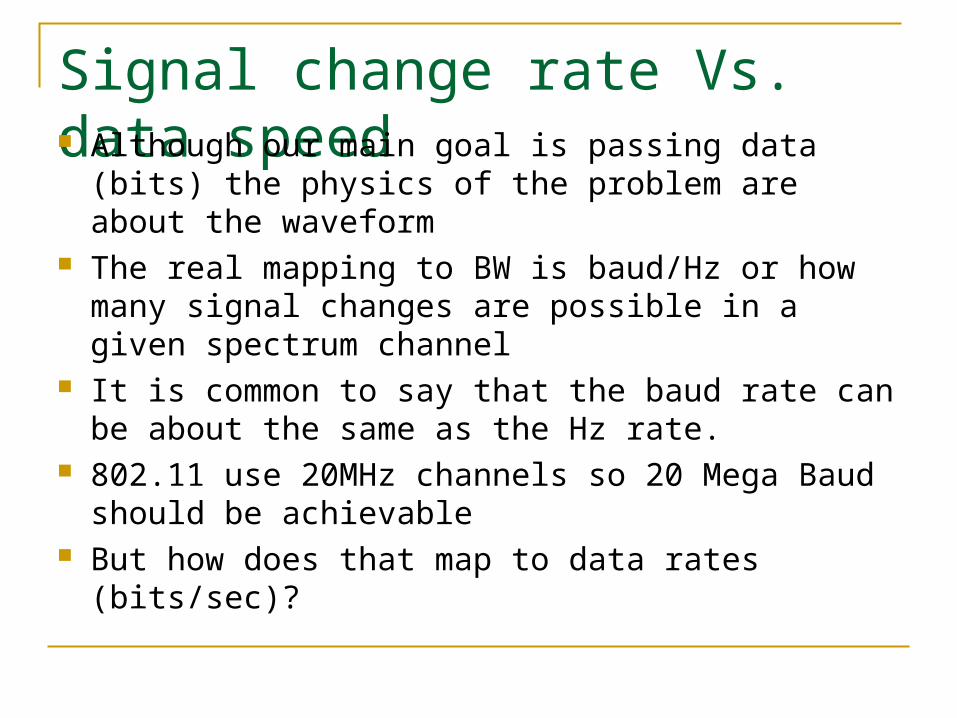
Signal change rate Vs. data speed Although our main goal is passing data (bits) the
physics of the problem are about the waveform The real mapping to BW is baud/Hz or how many
signal changes are possible in a given spectrum channel
It is common to say that the baud rate can be about the same as the Hz rate.
802.11 use 20MHz channels so 20 Mega Baud should be achievable
But how does that map to data rates (bits/sec)?
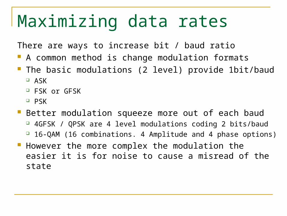
Maximizing data ratesThere are ways to increase bit / baud ratio A common method is change modulation formats The basic modulations (2 level) provide 1bit/baud
ASK FSK or GFSK PSK
Better modulation squeeze more out of each baud 4GFSK / QPSK are 4 level modulations coding 2 bits/baud 16-QAM (16 combinations. 4 Amplitude and 4 phase options)
However the more complex the modulation the easier it is for noise to cause a misread of the state

Signal distortion - multipath
Multipath is the same signal received in two different paths
Can cause destructive interference and time dispersion (inter symbol interference)

Signal distortion – Fading and noise A signal will fade as it propagates over the
media It will also pick up interference from other
signals in the same media/frequency As a result the signal to noise ration will get
worse and worse

The interference problem interpreting states in a modulated wave
depends on the signal quality. Errors can change one set of bits to another Any such change will corrupt the information CRC checks detect the corruption but we don’t
want to retransmit the whole packet/Frame A reasonable optical media BER is better
than10^-9, Good WLAN BER is 10^-5
Solutions for interference
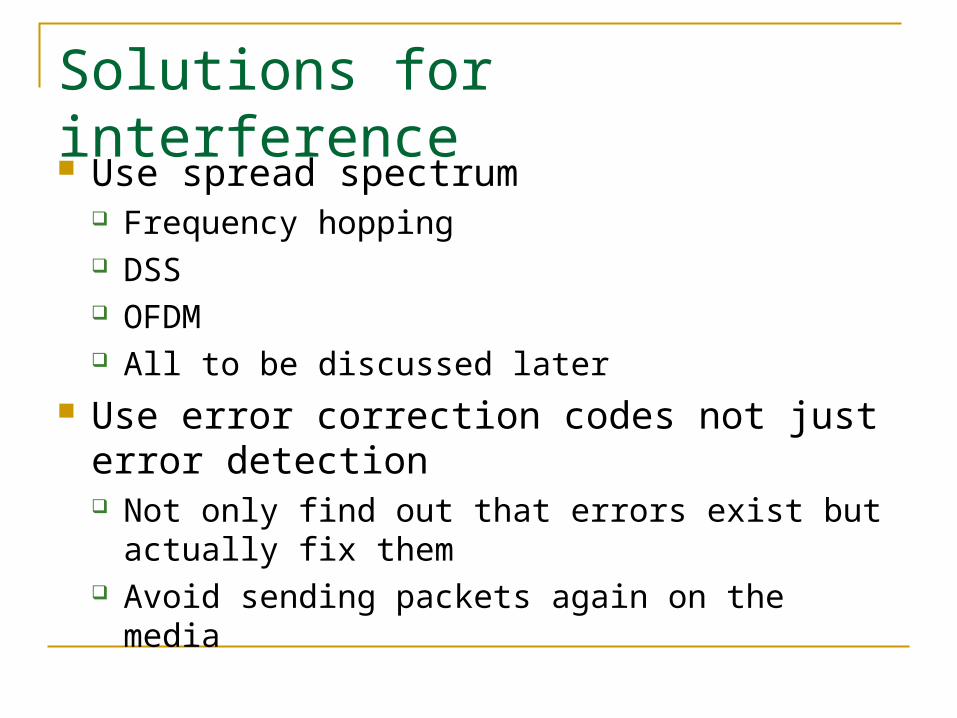
Use spread spectrum Frequency hopping DSS OFDM All to be discussed later
Use error correction codes not just error detection Not only find out that errors exist but actually fix
them Avoid sending packets again on the media

Error correction codes in 802.11 For the same encoding type the more
resilient the code the more the overhead required
Radio is especially noisy so strong error codes are required
Different 802.11 standards use different encodings
Line codes A specification of how to encode bits on the
physical media ‘0’ and ‘1’ can be encoded as any voltage
levels in cables (and any other physical characteristic elsewhere)
Line codes are used to code information on electrical media in order to reduce distortion
WLAN uses different line codes for different standards – we will see this in later slides
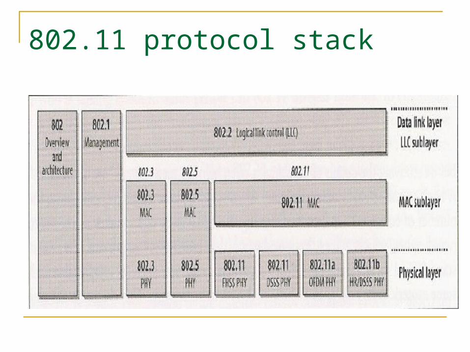
802.11 protocol stack

The two PHY sub layers
The PHY is itself split into two main sub layers PMD – transmits the frames onto the media. This
layer handles things like line coding, modulation and the like
PLCF – Physical Layer Convergence Procedure. maps the MAC packet into the physical layer. This layer handles the creation of preambles and headers specifying the PMD Deals with synchronization Specifies PMD type used and it’s characteristics Takes care of media sense for the L2 CSMA
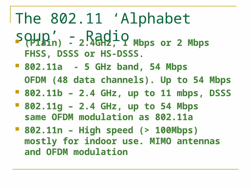
The 802.11 ‘Alphabet soup’ - Radio (Plain) - 2.4GHz, 1 Mbps or 2 Mbps
FHSS, DSSS or HS-DSSS. 802.11a - 5 GHz band, 54 Mbps
OFDM (48 data channels). Up to 54 Mbps 802.11b – 2.4 GHz, up to 11 mbps, DSSS 802.11g – 2.4 GHz, up to 54 Mbps
same OFDM modulation as 802.11a 802.11n – High speed (> 100Mbps) mostly for
indoor use. MIMO antennas and OFDM modulation

(plain) 802.11 - FHSS The FHSS uses frequency hopping.
Divides the available spectrum into 1MHz ‘slots’ Stay in one slot for a set period (dwell time) then move to
another Primary users only disrupt specific slots and look like transient
noise but allow the transmission to succeed Different hop sequences not sharing the same slots
are called orthogonal A number of orthogonal sets exist
The AP governs the hopping sequence The beacon specifies the index of the set and the sequence in
the set the cell is in

FHSS details Dwell time is 390 time units or about 0.4 sec Hopping takes no longer than 224 microseconds Number of available slots differ from US to Europe
US allows 80 channels and Europe/Japan about 40 With a simple two level encoding using GFSK 1MHz
means 1mbps so this is the basic speed of FHSS With 4GFSK (4 frequencies) you can achieve 2Mbps Higher rates are not practical with GFSK because detecting
the differences becomes problematic The PLCF headers are always encoded in 1mbps
Falling back to 1mbps for everything in higher noise
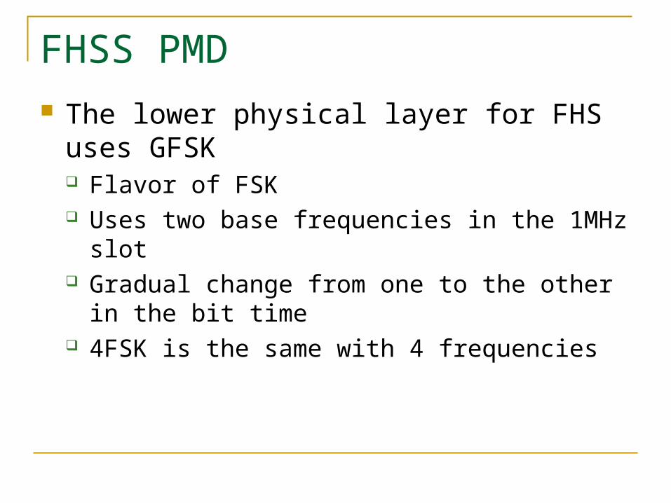
FHSS PMD The lower physical layer for FHS uses GFSK
Flavor of FSK Uses two base frequencies in the 1MHz slot Gradual change from one to the other in the bit
time 4FSK is the same with 4 frequencies

FHSS PLCP The PLCP builds the PLCP preamble and
header Preamble is an 80 bit sync sequence
(01010…) and a 16 bit start frame delimiter Header includes information on the L2 packet
the PDSU length word specify the L2 frame length PLCP signaling encode the speed (1 or 2mbps
only) The Header Error Check is a 16 bit CRC
We will not review the PLCP of other 802.11 flavors for brevity

(plain) 802.11 - DSSS Direct sequence is another spread spectrum
technique used by the plain 802.11 Interference avoidance is done by speeding up
the signal XOR bits with a higher speed (chipping) sequence Spreads the power over a wider band Less interference with primary transmitters in range Less cross interference

802.11 DSSS channel settings 11 Channels (in the US) in the 2.4 – 2.5 GHz are used,
(referred to as C-Band Industrial, Scientific, and Medical (ISM)).
Microwave ovens and some cordless phones operate in the same band
For 11 Mbps, Channels 1, 6, and 11 give the best non overlapping coverage

Barker code
The multiplication sequence in 802.11 DSSS is an 11 bit Barker code
Every bit is encoded as a sequence of 11 much faster bits (chips) The basic word is +1,-1,+1,+1,-1,+1,+1,+1,-1,-1,-1 Data bit 1 reserves the same word 0 means flip the word
Maximizes correlation and minimizes cross correlation
In other words make it as difficult as possible to mix 0/1

Barker modulation
(plain) 802.11 – IR
Initially the 802.11 protocol included an InfraRed option but it mostly unrealized and will not be discussed here
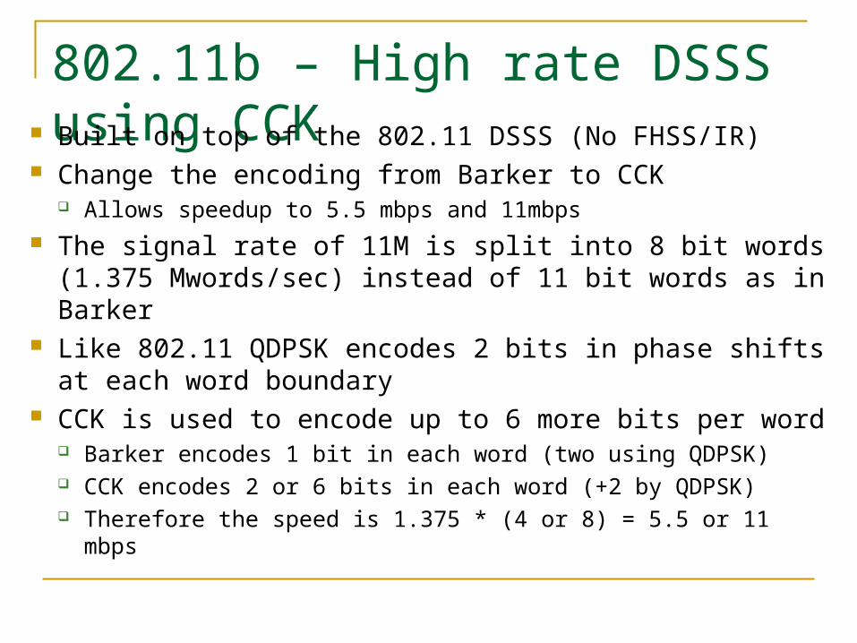
802.11b – High rate DSSS using CCK Built on top of the 802.11 DSSS (No FHSS/IR)
Change the encoding from Barker to CCK Allows speedup to 5.5 mbps and 11mbps
The signal rate of 11M is split into 8 bit words (1.375 Mwords/sec) instead of 11 bit words as in Barker
Like 802.11 QDPSK encodes 2 bits in phase shifts at each word boundary
CCK is used to encode up to 6 more bits per word Barker encodes 1 bit in each word (two using QDPSK) CCK encodes 2 or 6 bits in each word (+2 by QDPSK) Therefore the speed is 1.375 * (4 or 8) = 5.5 or 11 mbps

CCK coding explained CCK encodes bits by choosing an available 8 bit
sequence out of the total 256 available ones For 2 bit CCK this means using 4 of the 256 codes For 6 bit CCK this means using 62 of the 256 codes The selection is done to maximize self correlation
and minimize cross correlation In other words to minimize the chance of misinterpreting a
code The code word selections is detailed in the standard
and is based on an imaginary number formula But we will not go into the theory here
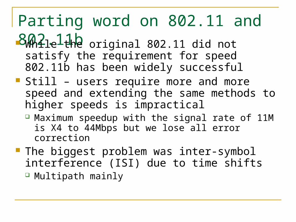
Parting word on 802.11 and 802.11b While the original 802.11 did not satisfy the
requirement for speed 802.11b has been widely successful
Still – users require more and more speed and extending the same methods to higher speeds is impractical Maximum speedup with the signal rate of 11M
is X4 to 44Mbps but we lose all error correction The biggest problem was inter-symbol
interference (ISI) due to time shifts Multipath mainly

802.11a/g – OFDM, 5GHz and 2.4 GHz In order to get higher speeds than those of
802.11b more efficient codes are required A completely new method derived – OFDM
Similar to DSL High number of low BW ‘modems’ are used, each
on a different sub channel The ‘slow’ sub channels are multiplexed into a
‘fast’ combined channel Error correction is done with FEC and bit stripping

OFDM spectrum usage
‘orthogonal’ because each carrier is set to not interfere with the others

OFDM explained OFDM stands for orthogonal frequency division
multiplexing Uses mathematical transformations to pass multiple
transmissions on the same carrier Encodes transmissions in multiple sub-carriers
(independent ‘modems’) Use bit stripping to pass each word on many channels Interference in constant frequency may kill some of the bits
but error correction codes can deal with that closely related to FDM

OFDM (2) However it uses no guard band between sub
carriers (channels) Sub carriers are easily distinguishable from each
other being orthogonal FFT is used to create a waveform from each
of the subcarriers FFT is used as a filter for noise Helps solve the ISI problem since it is not as
sensitive to time of arrival

OFDM (3) The ‘price’ for reduced ISI is sensitivity to frequency
shifts in the sub carriers (ICI) Doppler effects Transmitter/receiver oscillators out of sync
Solution – split transmission time to guard and data. Incurs overhead Delays shorter than the guard time do not cause problems Allow both sides to sense and compensate for distortion The data is transmitted in the ‘FFT integration’ time Guard time is also used to gradually build up the signal
strength for the FFT integration time and avoid high frequency components (windowing)

OFDM transmit/receive
Transmit
Receive

802.11a specific OFDM (1)
The 802.11a standards have a unique OFDM type Office buildings usually create delays spread of
40-70 ns but could be up to 200ns Guard time is usually X4 the expected delay 802.11a uses guard of 800 ns and 3.2 usec for
FFT integration Sub carrier spacing is 1/FFT integration = 0.3125
MHz Channels selected to be 20MHz each
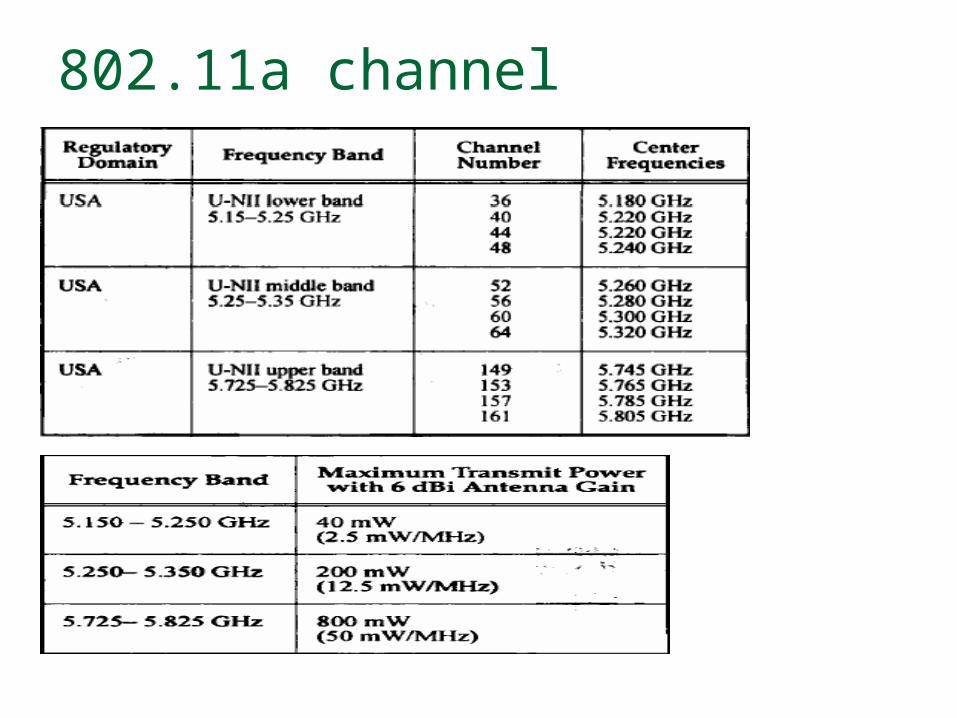
802.11a channel

802.11a spectrum layout

802.11a sub carriers
52 sub carriers 4 pilots to monitor path shift/ICE 48 data carriers
Each carrier carries 250K OFDM symbols Total speed varies according to the speed of
each sub carrier Different modulations (BPSK, QPSK, 16-QAM) Different error correction codes (½ , 2/3, ¾
payload bits per transmitted bits)

802.11a OFDM speedsData Rate
(Mbps)
Modulation Coding Rate Coded bits per
Coded bits per subcarrier
Coded bits per
OFDM symbol
Data bits per OFDM sybmol
6 BPSK ½ 1 48 24
9 BPSK ¾ 1 48 36
12 QPSK ½ 2 96 48
18 QPSK ¾ 2 96 72
24 16-QAM ½ 4 192 96
36 16-QAM ¾ 4 192 144
48 64-QAM 2/3 6 288 192
54 64-QAM ¾ 6 288 216
802.11n
A future standard set to achieve 100mbps data throughput About 250 mbps bit rate
Not a standard yet Suggestions include
multiple antennas (MIMO) Enhanced modulation and coding schemes Expanded bandwidths