wireless data gathering panel - interlogixstatic.interlogix.com/library/al-1231dgp_inin.pdf ·...
TRANSCRIPT

Installation and Programming Guide Wireless DGP AL-1231 Part number: 466-2025-US Rev. H April 2005
Wireless Data Gathering Panel (DGP) Model AL-1231
Installation
& Programming Guide
g GE Security

2 Installation and Programming Guide Wireless DGP AL-1231 Part number: 466-2025-US Rev. H April 2005
Contents Introduction
About this Guide ....................................................................................................................3 Wireless Data Gathering Panel — Introduction....................................................................4
Installation Topics........................................................................................................................ 5 Installation Overview..............................................................................................................6 Installing the Wireless DGP....................................................................................................7 Installation Troubleshooting ...............................................................................................12
Programming Topics.................................................................................................................. 13 Introduction .........................................................................................................................14 Selecting the Remote Wireless DGP Menu (Panel menu) ..................................................15 Programming a Sensor into the Wireless DGP (DGP menu 1)...........................................16 Programming a Sensor with Multiple Zones (DGP menu 1)..............................................19 Deleting a Wireless Sensor Zone (DGP menu 1).................................................................21 Viewing a Wireless Sensor’s ID Number (DGP menu 2) .....................................................22 Viewing the Zone Sensor Status (DGP menu 3)..................................................................23 Programming Users/Relay Fobs (DGP menu 4).................................................................24 Deleting or Changing the Details of a Fob (DGP menu 4).................................................27 Viewing Fob User/Relay Numbers (DGP menu 5)..............................................................28 Changing the Database Size (DGP menu 6) .......................................................................29 Programming the Supervision Time (DGP menu 7) ..........................................................30 Programming the Supervision Options (DGP menu 8)......................................................31 Programming the Tamper Switch Options (DGP menu 9)................................................32 Testing the Wireless Sensor Signal Strength (Installer Sensor Test) (DGP menu 10) ......33 Resetting the Wireless DGP to the Factory Defaults (DGP menu 12) .................................34 Checking Receiver RF Noise Level (DGP menu 13)............................................................35 Checking the State of a Zone (Panel menu) .......................................................................36 Radio Frequency (RF) Jam Sensing.....................................................................................37 Adding a Repeater to Increase Sensor Coverage .................................................................38
Requesting Technical Support .................................................................................................. 39 Ordering Sensors, Fobs and Repeaters ................................................................................39 FCC Compliance ..................................................................................................................40 Specifications........................................................................................................................40
Installation and Programming Guide Wireless DGP AL-1231 Part number: 466-2025-US Rev. H April 2005 3
About this Guide
How this guide is structured
This guide is the technician’s installation guide, and the programming guide after installation. It is arranged in three parts: 1. Installing and testing the hardware 2. Programming the Wireless DGP and using the inbuilt diagnostics 3. Miscellaneous topics. Even though the programming section presents each procedure in the same order as the Alliance System menu; don’t use the same order for installation programming. See page 5 for the correct installation sequence. This guide also contains basic instructions on how to program a repeater station into the Alliance System. Mounting the repeater is not covered.
Assumed knowledge: Technicians
For installers: All installation procedures assume a trained qualified installer will install the Wireless DGP and that your local cabling standards are met. Installation procedures assume installers are experienced with Alliance System Remote Arming Station (RAS) keypad programming and understand wireless sensor technology. For Technicians: No programming experience is assumed, but familiarity with using a RAS keypad to navigate the Alliance System menu is desirable.

4 Installation and Programming Guide Wireless DGP AL-1231 Part number: 466-2025-US Rev. H April 2005
Wireless Data Gathering Panel — Introduction
Product Features • The Wireless Data Gathering Panel receiver expands the Alliance System panel’s input capability
by up to 32 zones using GE Interlogix™ Learn Mode™ 319.5 MHz Wireless Transmitter Sensors — crystal or Surface Acoustic Wave (SAW).
• The Wireless DGP may be located up to 1100 feet (335 meters) from the Alliance System panel. • The Wireless DGP receives information from a range of compatible sensor types programmed into
the DGP. • The Wireless DGP features spatial diversity to minimize wireless signal nulls or dead spots and
has a nominal open-air receiving range of 1500 feet (460 m). • If dead spots need to be eliminated a GE Interlogix 319.5MHz repeater may be used. • The Wireless DGP may be powered from the Alliance System databus or a remote auxiliary power
supply. • Fob buttons may be programmed for users to arm and disarm or to control relays. For example, to
remotely open and close a garage door as well as arm or disarm an office security system.
Basic system layout Loop antenna DGP model shown.
Wireless DGP working with some of the possible sensors.
Alliance panel
Wireless Data Gathering Panel (DGP) AL1231
with several compatible wireless products
Databus

Installation and Programming Guide Wireless DGP AL-1231 Part number: 466-2025-US Rev. H April 2005 5
Installation Topics
Topic See Page Installation Kit 5 Installation Overview 6 Installation:
• Stage 1: Mount the Wireless DGP • Stage 2: Set the DIP switches • Stage 3: Connect the Wireless DGP to the Alliance System databus - Power
and Communication Connections • Stage 4: Power up the AL-1231 and Alliance System panel • Stage 5: Test the Connectivity to the Alliance System panel • Stage 6: Program the Wireless DGP into the Alliance System panel
6
Installation troubleshooting 12
Installation kit
Part √ Received 1 x AL-1231 Wireless DGP in plastic enclosure 2 x dipole antennas 4 x mounting screws and plastic plugs 1 x wall-tamper magnet (optional) 1 x Installation and Programming guide √ 1 x 470 Ω ¼ watt databus (RS485) termination resistor* * The first and the last devices on the databus must be terminated.

6 Installation and Programming Guide Wireless DGP AL-1231 Part number: 466-2025-US Rev. H April 2005
Installation Overview
Basic requirements and suggestions
• Requires version AL-40xx.04.05.10 Alliance System firmware or above. • Up to 15 DGPs may be connected to the Alliance System panel providing 240 wireless zones (also
known as inputs), or up to 240 fobs to arm/disarm area or activate/deactivate relay controls. • The maximum recommended databus length is 1100 feet (335 m) when one or more AL-1231
Wireless DGPs are connected. • Each Wireless DGP must have a unique DIP switch address. • Leave 7 inches (18 cm) above the Wireless DGP plastic enclosure for the antennas. • Avoid areas likely to expose the Wireless DGP to moisture. • Remove power from the Alliance System panel before commencing installation. • You must be free of static electricity before handling the printed circuit board. Wear a grounding
strap when opening the plastic enclosure. • Avoid excessive metal or electrical wiring, e.g. furnace & utility rooms. • As a general recommendation, locate the Wireless DGP central to all transmitter sensors. • Use the GE Interlogix 319.5 MHz Repeater to assist with range problems or receiver dead spots. If
unavoidable, mount on or near metal with the antennas extending above the metallic surface, as shown in the diagram on page 8.
Installation sequence
1. Mount the wireless DGP. 2. Set the Wireless DGP address DIP switch. 3. Wire the Wireless DGP to Alliance System databus. 4. Program the Wireless DGP into the Alliance System. (See programming guide.) 5. Test connectivity to Alliance System. 6. Mount sensors and 319.5 MHz Repeater (a Repeater can be added later if sensor performance
or signal strength is found to be inadequate.) 7. Decide Wireless DGP zone database size (16 or 32). 8. Program sensor or fob zones into the DGP. 9. Test. 10. Install repeater station if required.
Installation sequence flowchart
Wireless
databus

Installation and Programming Guide Wireless DGP AL-1231 Part number: 466-2025-US Rev. H April 2005 7
Installing the Wireless DGP
Procedure
Stage1: Mounting the Wireless DGP Step Action
1 Remove power from the Alliance System panel. 2 Remove the Wireless DGP plastic cover. Hold the base of the
Wireless DGP against the mounting surface and mark the three mounting holes. Leave 7 inches (18 cm) of free space above for the antenna. Press down here to remove the cover.
3 If back tamper is required, drill a 16 mm diameter hole and insert the back tamper magnet (supplied) so it will sit under the reed switch (next to DIP switches) after the unit is mounted. Make sure the back tamper magnet fits tightly in the drilled hole. Remove the two plastic accessories in the cable entry slot.
TIP: Remember to enable the rear tamper in the Wireless DGP menu option 9 - Tamper Options (see page 32).
4 Drill holes and insert screw anchors if required. 5 Secure to the wall with screws provided.
Continued on next page
Back tamper magnetmounted under reed
switch

8 Installation and Programming Guide Wireless DGP AL-1231 Part number: 466-2025-US Rev. H April 2005
Installing the Wireless DGP, Continued
Procedure (continued)
If mounting near metal, give the antenna as much clearance as possible. This applies to both loop antenna (shown) or dipole antennas (not shown).
6 Connect the four databus cable wires to the terminal strip on the DGP. A = D+ B = D –
7 Connect the databus cable directly to the Alliance System panel databus.
8 Insert the antenna into the innermost terminals of the antenna terminal block at the top of the circuit board and tighten the screws.
Stage 2: Set the DIP switches 1 Diagram: Wireless DGP address DIP switch settings
Continued on next page
+12V A B GND
Address 0
Address 1 Address 2 Address 3 Address 4
Address 5 Address 6 Address 7 Address 8
Address 9 Address 10 Address 11 Address 12
Address 13 Address 14 Address 15
(Address 0 not used)
On

Installation and Programming Guide Wireless DGP AL-1231 Part number: 466-2025-US Rev. H April 2005 9
Installing the Wireless DGP, Continued
Procedure (continued)
Each Wireless DGP connected to the Alliance System databus must identify itself to Alliance System panel with its own address, set with the DIP switches on the DGP. The diagram shows the DIP switch settings for 15 possible Wireless DGP addresses. Address 0 is a factory test setting — don’t use it.
Important note: Before adding a new Wireless DGP to an Alliance system with existing DGPs, check that the Wireless DGP at the preceding address is not programmed for more than 32 zones, i.e., if Wireless DGP 1 is programmed for 32 zones it uses the 1st 16 zones for Wireless DGP 1 and 2nd 16 zones for Wireless DGP 2. Therefore don’t poll Wireless DGP address 2. Example: DGP 1 was installed six months ago with 32 zones. Adding Wireless DGP 2 today and activating sensors for zones 33-48 will create confusing event messages. Instead, add today’s Wireless DGP as Wireless DGP 3.
2 Replace the plastic cover. Make sure the cover tamper switch extension spring is in place on the tamper switch.
Stage 3: Connect the Wireless DGP to the Alliance System databus - Power and Communication Connections
Continued on next page
Wiring Diagram:Single Wireless
DGP wireddirectly to the
Alliance systemLAN connection.
+

10 Installation and Programming Guide Wireless DGP AL-1231 Part number: 466-2025-US Rev. H April 2005
Installing the Wireless DGP, Continued
Procedure (continued)
Databus connection wiring: +12 • Positive connection to the databus 12 V DC supply or remote auxiliary
power supply • Max. current drawn by the Wireless DGP is 30 mA • Max. voltage is 13.8 V
A • RS485 Data +
B • RS485 Data –
GND • Ground connection to the databus 12 V DC supply or auxiliary power supply.
Databus wiring connection notes
• The AL-1231 Wireless DGP is not fitted with a databus termination link. Use a 470 Ω ¼ watt resistor if the unit is either the first or last unit on the databus.
• The recommended databus cable is Belden 8723, 2-pair twisted, shielded data cable. • The maximum recommended databus length is 1100 feet (335 m) when one or more AL-1231
Wireless DGP is connected • The shield of each length of data cable is normally connected to the system earth at one end
only. • The AL-1231 Wireless DGP is not fitted with an earth terminal. • The Earth terminal of all other devices in the system fitted with earth terminals must be
connected properly to one common earth point via a separate earth wire run with the databus to the panel.
• The separate earth wire must be at least 0.01 inches (2.5 mm2). • We recommend a heavier gauge for long cable runs. • Wiring must be installed in accordance with local guidelines. Stage 4: Power up the AL-1231 and the panel
1 Verify that all wiring to the panel and Wireless DGP is correct. 2 Connect the Alliance System battery and AC power pack. 3 Check the Wireless DGP status LED (center of the DGP’s front
cover) is ON. TIP: Rx (Receive) and Tx (Transmit) LEDs aren’t provided on
the Wireless DGP. If the Wireless DGP LED is not ON, disconnect power and see the troubleshooting notes below.
Stage 5: Test the DGP Receiver 1 Activate a sensor (Alarm or Tamper) and check that the DGP
status LED flashes about eight times for each activation. Stage 6: Program the Wireless DGP into the panel
1 At the panel RAS keypad: press * [MENU] > Key in the installer code [1278] > press [19] > press [ENTER] > press [4] > press [ENTER] and the RAS screen will display:
Continued on next page
Poll DGP:

Installation and Programming Guide Wireless DGP AL-1231 Part number: 466-2025-US Rev. H April 2005 11
Installing the Wireless DGP, Continued
Databus wiring connection notes (continued)
2 Key in the address of the Wireless DGP (‘1’ in this example), and then press [ENTER]. The screen will display:
TIP: A comma after the 1 indicates that DGP 1 is polling successfully, and the colon after the 2 indicates that DGP 2 is offline or not connected. Press [* MENU] to update the menu.
3 Press [# ENTER]. You’ll be prompted to set the DGP type: Key in the address of the Wireless DGP (‘1’ in this example), and then press [ENTER].
4 The RAS screen will display: Key in [3] to select the Wireless DGP type, and then press [#ENTER].
5 The RAS screen will display: Press [# ENTER] to exit.
Stage 7: Testing Receiver Performance 1 Program sensors into the DGP as per programmers’ guide.
2 Check that the RF Noise level is within limits (see page 35) the DGP may need to be relocated if the RF noise floor is too high.
3 Check that the signal strength of each sensor is within limits (see page 33) If a sensor signal strength is too low, the sensor may need to be relocated or a 319.5 MHz Repeater or an additional AL-1231 DGP installed closer to the sensor
1, 2: Poll DGP:
Set DGP typeDGP no:
Wireless DGP (433 MHz)Type:
StandardType:

12 Installation and Programming Guide Wireless DGP AL-1231 Part number: 466-2025-US Rev. H April 2005
Installation Troubleshooting
Problem Action/Solution The Wireless DGP module status LED stays off when power is applied.
• Check for incorrect wiring connections. • Make sure the Alliance System Panel is
powered correctly. • Measure Wireless DGP DC power with a
multimeter. (Should be 13.8 V DC). • If the LED still remains off, replace the
Wireless DGP module. The Wireless DGP module status LED stays lit but doesn’t flash when wireless devices are activated.
• Check Wireless DGP antenna connections • Check for Wireless DGP antenna proximity to
metal obstructions such as ducting or AC wiring.
• Make sure the sensor transmitters are the correct frequency, that is, 319.5 MHz
• If LED still doesn’t flash, replace the DGP. The Wireless DGP status LED stays lit and flashes when wireless devices are activated, but Alliance System doesn’t respond
• Check that DIP switch address 0 is not selected on the DGP.
• Check Wireless DGP databus connections. • Check that each Wireless DGP connected to
the databus has a unique address. • Check that the Wireless DGP is being polled by
(Alliance System Menu 19 > 4.) • Check that the Transmitter sensor is
programmed into the Wireless DGP See Programming Guide
• If the Alliance system still doesn’t respond, try replacing the Wireless DGP module.

Installation and Programming Guide Wireless DGP AL-1231 Part number: 466-2025-US Rev. H April 2005 13
Programming Topics
Introduction ............................................................................................................................. 14 Selecting the Remote Wireless DGP Menu (Panel menu) ...................................................... 15 Programming a Sensor into the Wireless DGP (DGP menu 1)............................................... 16 Programming a Sensor with Multiple Zones (DGP menu 1) .................................................. 19 Deleting a Wireless Sensor Zone (DGP menu 1)..................................................................... 21 Viewing a Wireless Sensor’s ID Number (DGP menu 2) ......................................................... 22 Viewing the Zone Sensor Status (DGP menu 3)...................................................................... 23 Programming Users/Relay Fobs (DGP menu 4)..................................................................... 24 Deleting or Changing the Details of a Fob (DGP menu 4) ..................................................... 27 Viewing Fob User/Relay Numbers (DGP menu 5).................................................................. 28 Changing the Database Size (DGP menu 6) ........................................................................... 29 Programming the Supervision Time (DGP menu 7) .............................................................. 30 Programming the Supervision Options (DGP menu 8).......................................................... 31 Programming the Tamper Switch Options (DGP menu 9).................................................... 32 Testing the Wireless Sensor Signal Strength (DGP menu 10) ................................................ 33 Resetting the Wireless DGP to the Factory Defaults (DGP menu 12) ..................................... 34 Checking Receiver RF Noise Level (DGP menu 13)................................................................ 35 Checking the State of a Zone (Panel menu) ........................................................................... 36

14 Installation and Programming Guide Wireless DGP AL-1231 Part number: 466-2025-US Rev. H April 2005
Introduction
Before you start • Read the Wireless DGP installation guide
• Before starting programming set the Wireless DGP address, and poll the Wireless DGP to check it communicates with the Alliance System panel.
• Enter all data at the RAS keypad.
Important tips
to avoid problems after installation!!
1. To avoid problems, just after installation program the database size first (16 or 32 zones, see page 29). 2. Before adding a new Wireless DGP to a system with an existing DGP, always check which zones the existing Wireless DGP is using; that is: is it using 32 zones, including the zones for the Wireless DGP you’re about to add? Example: Wireless DGP 1 was installed six months ago with 32 zones. Adding Wireless DGP 2 today and activating sensors for zones 33-48 will create confusing event messages. Instead, add today’s new Wireless DGP as Wireless DGP 3.
Operating mode The Wireless DGP has two possible operating modes: extended and standard.
Extended mode: • Alliance System panel firmware version AL-40xx.04.05.10 and later required. • GE Interlogix two and four-button fobs can be used for arm/disarm functions and to control
relays. • All 16 or 32 zones are available.
Standard mode: • Fewer features than extended mode. Do not use.
Installation programming summary
1. Program a new Wireless DGP into the Alliance System 2. Program a repeater if one is used 3. Program the Wireless DGP database size (max. number of zones) 4. Program the sensors or fobs 5. Complete any other programming required.

Installation and Programming Guide Wireless DGP AL-1231 Part number: 466-2025-US Rev. H April 2005 15
Selecting the Remote Wireless DGP Menu (Panel menu)
Introduction You must select the remote Wireless DGP programming menu using the RAS
keypad.
Procedure Step > Action
Step 1: At the RAS Keypad > press [*MENU]> key in [Installer’s code] > then [ENTER] key in [19] > then [ENTER] to access installer’s menu > key in [* MENU] then [ENTER] for advance options and key in [28]> then [ENTER] and the keypad will display:
Step 2: Key in [1] for Remote Type Wireless DGP > press [ENTER] and the RAS will display:
Step 3: Key in the number of the Wireless DGP (same as DIP switch number for the DGP) > press [ENTER]. The RAS will identify the DGP and the firmware version.
Remote DGP Setup: DGP No: __
GE Interlogix AL1231.VXX 0-Exit Menu:__
Remote Type: 1-DGP, 2-RASType No: __

16 Installation and Programming Guide Wireless DGP AL-1231 Part number: 466-2025-US Rev. H April 2005
Programming a Sensor into the Wireless DGP (DGP menu 1)
Introduction Each sensor must be programmed into the Wireless DGP database via an
Alliance System RAS keypad. In this procedure it’s assumed the: • Sensor you are programming requires only one zone • The DIP switch address for the Wireless DGP is correct (See page 8.) • The DGP’s database size have been correctly selected and programmed (see page 29) • Sensors are physically installed or mounted • The repeater has been installed and programmed if required. (See pages 38 and 16.)
This section also lists the sensor activation switches, Wireless DGP zone ranges and Contact ID error codes. Programming fobs is described on page 24.
Procedure Step > Action Step 1: At the RAS keypad: press [* MENU] > key in [install code] > press
[# ENTER] > key in [19] > press [# ENTER] > press [* MENU] and key in [28] for the advanced menu > press [# ENTER] and the RAS will display:
Step 2: Key in [1] for Wireless DGP > press [ENTER] and the RAS will display:
Step 3: In this example the Wireless DGP’s no. or address is 1, as set by the Wireless DGP DIP switch. Key in [1] > press [ENTER]. The RAS will identify the DGP:
Step 4: Key in [1] > press [ENTER] for the first DGP menu option. The first zone will always appear. Asterisks **** next to the zone number indicate an available zone, as shown in the RAS display below: At this point you can:
• Program an empty zone • Move to a specific zone by typing in the number and pressing [ENTER]. • Delete the zone (see page 27).
Continued on next page
Program (17-32): 17 ****Type No: __
Remote DGP Setup: DGP No: __
GE Interlogix AL-1231.Vxx0-Exit Menu:
Remote Type: 1-DGP, 2-RASType No: __

Installation and Programming Guide Wireless DGP AL-1231 Part number: 466-2025-US Rev. H April 2005 17
Programming a Sensor into the Wireless DGP (DGP menu 1), Continued
(continued) Step 5: (In this example, a PIR is being programmed for DGP zone 17.)
Activate the sensor. (See Table 1 below.) Two beeps sound when the DGP receives the signal from the sensor. If seven beeps sound, the sensor was already in the database. Once the DGP zone has been updated with the new sensor, you’ll be prompted to activate the next zone or exit:
Other options: To see the zone you’ve just programmed, key in its number (in this case 17) > press [# ENTER]. The RAS will display the DGP number and a short name (for example PIR) to identify the sensor. To move to the next zone, key in the zone number you need, e.g. 20.
Table 1: Program Activation Switch
This table lists how to activate the programming switch
Sensor type How to activate each sensor’s programming switch 2-Button Fob Press and hold the Lock and Unlock buttons together until the Fob’s LED
flashes 4-Button Fob Press and hold the Lock and Unlock buttons together until the Fob’s LED
flashes Door Window Sensor (DWS)
Remove front cover (Tamper)
Freeze Sensor Remove the top cover to operate tamper Glassbreak or Universal Transmitter
Remove front cover to operate tamper
Panic Button Press the panic button PIR Remove the rear cover to operate tamper Rate-Of-Rise (Thermal Detector)
Press switch near the rear of the 9-volt battery
Repeater Open Tamper connector near battery terminals Shock Sensor Press rear tamper with cover on. Release rear tamper. Smoke Detector Remove detector from ceiling mounting base to operate tamper.
Continued on next page
Program (17-32): 18 *****0-Exit:__
Program (17-32): 17 PIR0-Exit: 20

18 Installation and Programming Guide Wireless DGP AL-1231 Part number: 466-2025-US Rev. H April 2005
Programming a Sensor into the Wireless DGP (DGP menu 1), Continued
Table 2: DGP input ranges
This table lists the DGP’s ranges in extended mode for 16 and 32 zone databases.
Wireless DGP Address 16-Zone Database 32-Zone Database
1 17 to 32 17 to 48 2 33 to 48 33 to 64 3 49 to 64 49 to 80 4 65 to 80 65 to 96 5 81 to 96 81 to112 6 97 to 112 97 to 128 7 113 to 128 113 to 144 8 129 to 144 129 to 160 9 145 to 160 145 to 176 10 161 to 176 161 to 192 11 177 to 192 177 to 208 12 193 to 208 193 to 224 13 209 to 224 209 to 240 14 225 to 240 225 to 256 15 241 to 256 241 to 256
TIP: If the DGP 1 is been programmed with 32 zones, then the next 16 zones (33-48) normally belonging to DGP 2 will now belong to DGP 1 and the RAS display would show 17-48.
Table 3: DGP status
This table lists the DGP status events, Ademco Contact ID and SIA codes.
DGP Event History Ademco Contact ID SIA Small Large Small Large
Open Yes E145 00 C006 E145 00 Czzz TA 0 TA 301-316 DGP Hardware Tamper Closed Yes R145 00 C006 R145 00 Czzz TR 0 TR 301-316 DGP CPU Restart Yes E305 00 C003 E305 00 Czzz – RR 301-316 DGP DIP Switch Change (16/32 zones)
Yes – E304 00 Czzz – –
RF Jamming Fault Yes E344 00 C020 E344 00 Czzz XQ 0 XQ 301-316 RF Jamming Restored Yes R344 00 C020 R344 00 Czzz XH 0 XH 301-316 Symbols used above zzz Refers to the DGP address. C065 to C079 are DGP addresses 1 to 15. Example: Contact ID message C066 refers to DGP 2.

Installation and Programming Guide Wireless DGP AL-1231 Part number: 466-2025-US Rev. H April 2005 19
Programming a Sensor with Multiple Zones (DGP menu 1)
Introduction Some sensors can be connected to more than one zone. A Door Window
Sensor (DWS) for example can use two zones. In the example below, the first zone for the door reed switch under the DWS sensor cover is programmed. Then the second zone, the DWS window tapes are programmed. • This procedure is slightly different to programming a single zone, even though the starting point in
the RAS DGP menu is the same. The difference is that [# ENTER] is pressed when asterisks are displayed, instead of activating the sensor immediately.
• If the DGP zone database doesn’t have enough spare zones (e.g. the database has one spare zone left, but two are required) the system will accept any zones it has room for, in this case, the first, and ignore the rest.
Programming Fobs: For instructions for programming fobs see page 24.
Procedure Step > Action Step 1: At the RAS press [* MENU] > key in [install code] > press [# ENTER]
> key in [19] > press [# ENTER] > press [* MENU] and key in [28] for the advanced menu > press [# ENTER] > key in [1] > press [# ENTER] > key in 1 to 15 [DGP number] > press [# ENTER].
Step 2: Key in [1] at the Wireless DGP menu > press [# ENTER]. The first free zone (with asterisks **** after the zone number indicate a free zone) will display, and the zone database size and zone range in brackets, here as (17-32)
Step 3: Press [# ENTER] and the RAS will display: (The default is 1 zone.)
Step 4: For this example, key in [2](the DWS has 2 zones) > press [# ENTER]. The RAS will display:
Continued on next page
How many zones 1(1-4):__
How many zones 2(1-4):__
Program (17-32): 17****0-Exit:__

20 Installation and Programming Guide Wireless DGP AL-1231 Part number: 466-2025-US Rev. H April 2005
Programming a Sensor with Multiple Zones (DGP menu 1), Continued
(continued) Procedure Step > Action Step 5: Press [# ENTER] and the RAS will display.
Step 6: Now activate the sensor’s programming input and two beeps will sound. The RAS will display the first available zone:
Options: To go back and check inputs just programmed (i.e. inputs 17-18), key in [17] > press [# ENTER]. The RAS will display the details for the previously programmed zone:
Press * [MENU] to see the details for this sensor’s second zone, and the RAS will display:
Program (17-32): 19 ****0-Exit:__
Press program switch#-Exit
Program (17-32): 17 DWS 10-Exit:__
Program (17-32): 18 DWS 20-Exit:__

Installation and Programming Guide Wireless DGP AL-1231 Part number: 466-2025-US Rev. H April 2005 21
Deleting a Wireless Sensor Zone (DGP menu 1)
Basic concepts for deleting or changing sensors
• Deleting a wireless sensor zone removes it from the DGP zone database. • Changing a wireless sensor zone: To change the details of a zone, the zone must be deleted first,
and then added as a new wireless sensor zone.
• Changing or deleting Fobs: Read more about the separate procedures for fobs, on page 27.
Procedure Step > Action Step 1: At the RAS press [* MENU] > key in [install code] > press [# ENTER]
> key in [19] > press [# ENTER] > press [* MENU] and key in [28] for the advanced menu > press [# ENTER] > key in [1] > press [# ENTER] > key in 1 to 15 [DGP number] > press [# ENTER].
Step 2: Key in [1] > press [# ENTER] and then key in the number of the zone you wish to delete > press [# ENTER]. The RAS will display the zone’s details. (In this example we’re deleting zone number 19 from the DGP database.)
Step 3: To delete this DWS at zone 19 (this sensor actually uses two zones, 18 &19), press [# ENTER] and the RAS will display:
Step 4: Press * [MENU] key to delete the DWS. If the sensor uses more than one zone (e.g. in this case it uses zones 18 & 19), any other zone it uses is automatically cleared from the DGP zone database. Asterisks will appear indicating the zone has been cleared and is available.
Delete Device?* - Yes # - No
Program (17-32): 19 ****0-Exit:__
Program (17-32): 19 DWS 20-Exit:__

22 Installation and Programming Guide Wireless DGP AL-1231 Part number: 466-2025-US Rev. H April 2005
Viewing a Wireless Sensor’s ID Number (DGP menu 2)
Introduction Every wireless sensor has a unique factory programmed number, visible in the
RAS. Use this procedure to identify the sensor’s ID number if required or to identify the type of sensor.
Procedure Step > Action Step 1: At the RAS press [* MENU] > key in [install code] > press [# ENTER]
> key in [19] > press [# ENTER] > press [* MENU] and key in [28] for the advanced menu > press [# ENTER] > key in [1] > press [# ENTER] > key in 1 to 15 [DGP number] > press [# ENTER].
Step 2: Key in [2] > press [ENTER]. The RAS screen below will prompt you for the input number:
Step 3: Key in the input number you wish to view the ID number for, in this case [17] > press [ENTER]. The RAS will display the sensor’s unique, factory programmed ID number:
Asterisks **** will appear instead of an ID number if the zone (in this example zone 17) isn’t programmed: Key in 0 (zero) to exit.
17: 4BC22F: PIR *- Prev 0- Exit:__
17: 0:***** *-Prev 0-Exit:__
Zone number (17-32)?0-Exit:__

Installation and Programming Guide Wireless DGP AL-1231 Part number: 466-2025-US Rev. H April 2005 23
Viewing the Zone Sensor Status (DGP menu 3)
Introduction You can check the status of a zone input sensor. Depending on the sensor type,
there are six possible sensor warning messages:
Warning Description Normal Operating normally Alarm Zone in alarm Tamper Tamper Supervsn Supervision Fail. See Supervision Options on page 31. Batt Low battery warning Dirty Smoke detectors only
Procedure Step > Action Step 1: At the RAS press [* MENU] > key in [install code] > press [# ENTER]
> key in [19] > press [# ENTER] > press [* MENU] and key in [28] for the advanced menu > press [# ENTER] > key in [1] > press [# ENTER] > key in 1 to 15 [DGP number] > press [# ENTER].
Step 2: Key in [3] for the input status menu. Key in the input number required (in this case 17 is used) > press [# ENTER]. The RAS will display one or more of the six possible conditions below depending on the sensor type. See the table above for details.
17: Normal *-Prev, 0-Exit
17: Tamper *-Prev, 0-Exit
17: Supervsn *-Prev, 0-Exit
17: Dirty *-Prev, 0-Exit
Input number (17-32)? 0-Exit:__
17: Batt *-Prev, 0-Exit
17: Alarm *-Prev, 0-Exit

24 Installation and Programming Guide Wireless DGP AL-1231 Part number: 466-2025-US Rev. H April 2005
Programming Users/Relay Fobs (DGP menu 4)
Introduction Two and four-button fobs are programmed in a separate part of the DGP
zone database. Fob button sets can be programmed in five combinations of relays and users. • A user represents a person or alarm group (with automatic access to arm and disarm allocated
areas), and, is identified as a user number from 1 to 65,535. • Relays activate and de-activate devices (such as garage doors or lights) and can be a number
from 1 to 255. • This option is only available in extended mode.
Fob sets and buttons explained
Fob buttons are arranged in two sets (or rows):
• Set 1: buttons 1 & 2.
• Set 2: buttons 3 & 4.
Fob sets can be programmed as: • 2 users (set 1=user 1, set 2 = user 2)
• 2 relays (set 1= relay 1, set 2 = relay 2)
• 1 user and 1 relay (set 1= user 1, set 2 = relay 1)
• 1 user (set 1= user 1, set 2 = not used)
• 1 relay (set 1= relay 1, set 2 = not used)
TIPS:
Once a fob button is programmed as a user to arm areas or to activate relays, the second button in the set is available to disarm the area or de-activate the relay.
When programming a 1-set, 2-button fob, skip the menu option for fob set 2, by pressing [ENTER].
Continued on next page
Armareas
Activate relays
Disarm areas
Deactivate Relays

Installation and Programming Guide Wireless DGP AL-1231 Part number: 466-2025-US Rev. H April 2005 25
Programming Users/Relay Fobs (DGP menu 4), Continued
Procedure Step > Action Step 1: At the RAS press [* MENU] > key in [install code] > press [# ENTER]
> key in [19] > press [# ENTER] > press [* MENU] and key in [28] for the advanced menu > press [# ENTER] > key in [1] > press [# ENTER] > key in 1 to 15 [DGP number] > press [# ENTER].
Step 2: Key in [4] > press [# ENTER] and the RAS will display:
TIP: If the fob has already been programmed, the RAS will prompt you to delete the fob. Read more about deleting fobs on page 27.
Step 3: Key in [1] and press [# ENTER] to program the first fob input. The RAS will display:
Step 4: Press both top fob buttons until the fob LED flashes to initiate the fob. The display will give two beeps and show:
Step 5: You can now program button set one (top buttons 1 and 2) as a user or a relay. If you wish to program a user, key in [1], if you wish to program relays, key in [2]. (In this example we’re programming the top fob set as a user.) > press [# ENTER], the RAS will display:
Step 6: Key in the user’s number > press [# ENTER], and the display will change to the second set of fob buttons — whether there are one or two sets to be programmed. If there’s one set, press [# ENTER] to bypass the options for the second set and end the programming for this fob. Otherwise, continue the programming for the second set as described in step 7.
Continued on next page
Press Program Switch #-Exit
1: 1-User, 2-Relay Option:__
Button Set 1 User No:__
2: 1-User, 2-Relay Option:___
Fob No.(1-16) 0-Exit:__

26 Installation and Programming Guide Wireless DGP AL-1231 Part number: 466-2025-US Rev. H April 2005
Programming Users/Relay Fobs (DGP menu 4), Continued
(continued)
Procedure Step > Action Step 7: Decide if you want the second set to be a user or relay. In this case it is
a relay, so key in [2] and the RAS will display:
Step 8: Key in the relay number and press [# ENTER]. The data for two sets of fob buttons is now programmed in the DGPs fob database. The RAS will display: To add another fob, simply restart the procedure at Step 1 above.
Button Set 2 Relay No:__
Fob No. (1-16) 0-Exit:__

Installation and Programming Guide Wireless DGP AL-1231 Part number: 466-2025-US Rev. H April 2005 27
Deleting or Changing the Details of a Fob (DGP menu 4)
Deleting and changing fob details
To delete a fob follow the directions below. To change the details of a fob, delete the fob first and then re-enter details as a new fob. (See previous section on programming fobs.)
Procedure Step > Action Step 1: At the RAS press [* MENU] > key in [install code] > press [# ENTER]
> key in [19] > press [# ENTER] > press [* MENU] and key in [28] for the advanced menu > press [# ENTER] > key in [1] > press [# ENTER] > key in 1 to 15 [DGP number] > press [# ENTER].
Step 2: Key in [4] > press [# ENTER], and then key in the number of the fob you wish to delete. If the fob exists in the database the RAS will display: Press [* MENU] to delete the fob or press [# ENTER] to return to the fob-programming screen. All elements of the fob will be cleared from the database. Press [0] (zero) to exit the menu.
Delete Fob? *-Yes, #-No
28 Installation and Programming Guide Wireless DGP AL-1231 Part number: 466-2025-US Rev. H April 2005
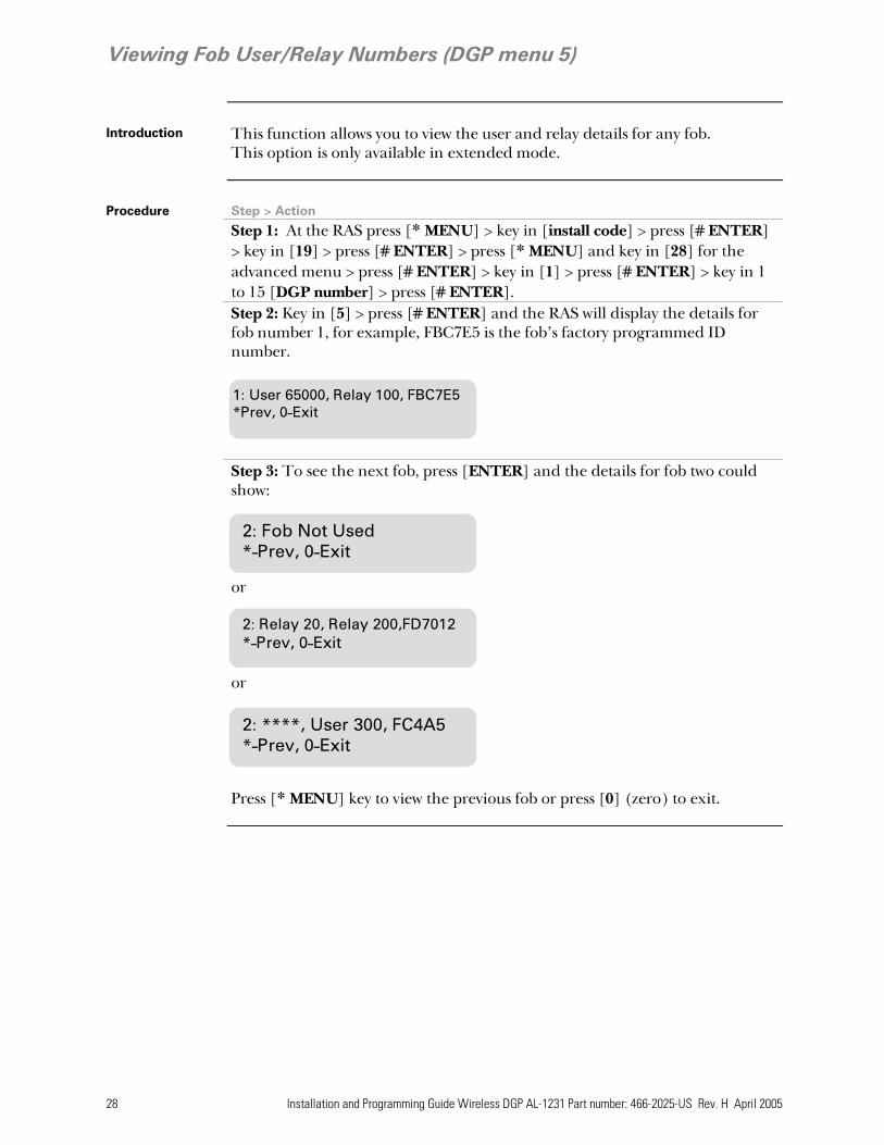
Viewing Fob User/Relay Numbers (DGP menu 5)
Introduction This function allows you to view the user and relay details for any fob.
This option is only available in extended mode.
Procedure Step > Action Step 1: At the RAS press [* MENU] > key in [install code] > press [# ENTER]
> key in [19] > press [# ENTER] > press [* MENU] and key in [28] for the advanced menu > press [# ENTER] > key in [1] > press [# ENTER] > key in 1 to 15 [DGP number] > press [# ENTER].
Step 2: Key in [5] > press [# ENTER] and the RAS will display the details for fob number 1, for example, FBC7E5 is the fob’s factory programmed ID number.
Step 3: To see the next fob, press [ENTER] and the details for fob two could show: or or
Press [* MENU] key to view the previous fob or press [0] (zero) to exit.
2: Fob Not Used*-Prev, 0-Exit
2: Relay 20, Relay 200,FD7012*-Prev, 0-Exit
2: ****, User 300, FC4A5*-Prev, 0-Exit
1: User 65000, Relay 100, FBC7E5 *Prev, 0-Exit
Installation and Programming Guide Wireless DGP AL-1231 Part number: 466-2025-US Rev. H April 2005 29
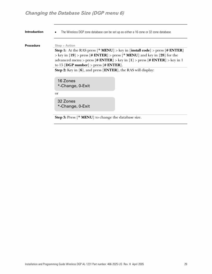
Changing the Database Size (DGP menu 6)
Introduction • The Wireless DGP zone database can be set up as either a 16-zone or 32-zone database.
Procedure Step > Action Step 1: At the RAS press [* MENU] > key in [install code] > press [# ENTER]
> key in [19] > press [# ENTER] > press [* MENU] and key in [28] for the advanced menu > press [# ENTER] > key in [1] > press [# ENTER] > key in 1 to 15 [DGP number] > press [# ENTER].
Step 2: Key in [6], and press [ENTER], the RAS will display: or
Step 3: Press [* MENU] to change the database size.
16 Zones *-Change, 0-Exit
32 Zones *-Change, 0-Exit
30 Installation and Programming Guide Wireless DGP AL-1231 Part number: 466-2025-US Rev. H April 2005
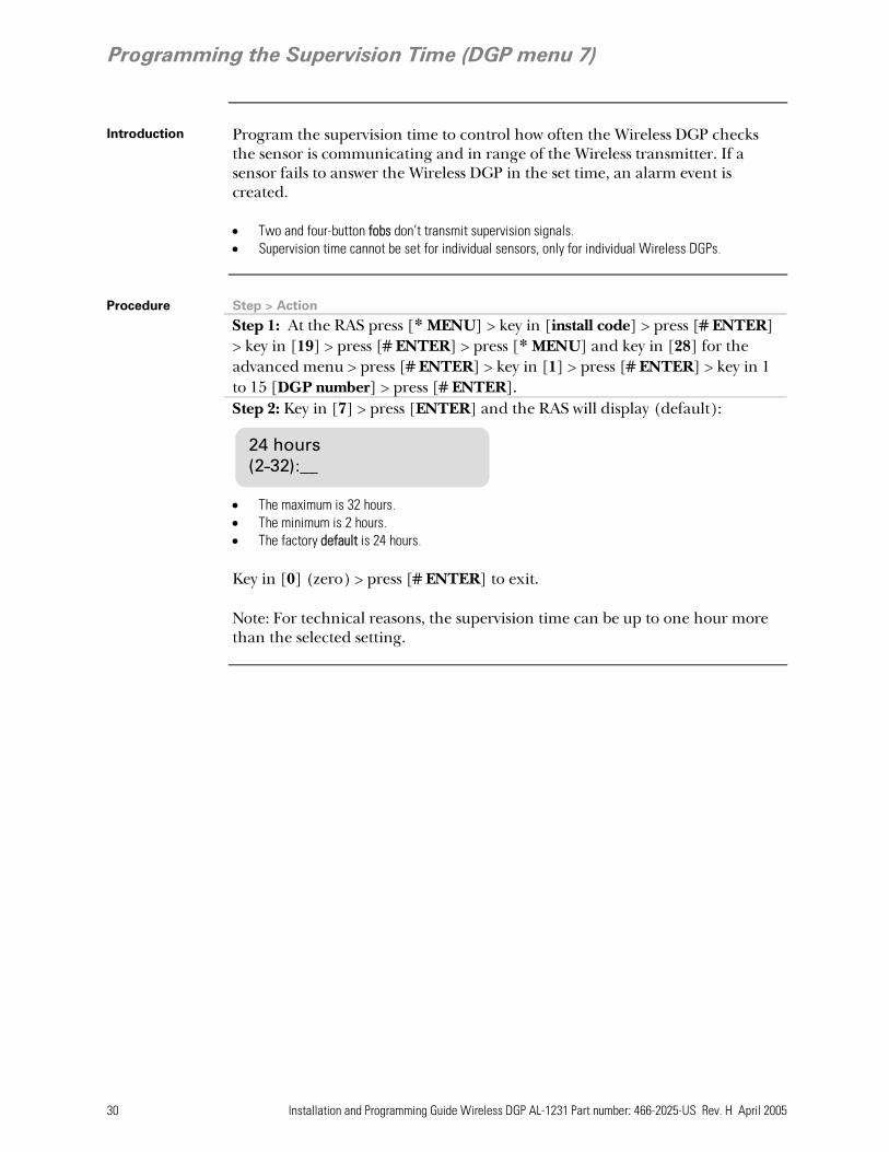
Programming the Supervision Time (DGP menu 7)
Introduction Program the supervision time to control how often the Wireless DGP checks
the sensor is communicating and in range of the Wireless transmitter. If a sensor fails to answer the Wireless DGP in the set time, an alarm event is created. • Two and four-button fobs don’t transmit supervision signals. • Supervision time cannot be set for individual sensors, only for individual Wireless DGPs.
Procedure Step > Action Step 1: At the RAS press [* MENU] > key in [install code] > press [# ENTER]
> key in [19] > press [# ENTER] > press [* MENU] and key in [28] for the advanced menu > press [# ENTER] > key in [1] > press [# ENTER] > key in 1 to 15 [DGP number] > press [# ENTER].
Step 2: Key in [7] > press [ENTER] and the RAS will display (default): • The maximum is 32 hours. • The minimum is 2 hours. • The factory default is 24 hours. Key in [0] (zero) > press [# ENTER] to exit.
Note: For technical reasons, the supervision time can be up to one hour more than the selected setting.
24 hours (2-32):__

Installation and Programming Guide Wireless DGP AL-1231 Part number: 466-2025-US Rev. H April 2005 31
Programming the Supervision Options (DGP menu 8)
Introduction • The supervision function monitors sensors at the interval set up in the previous procedure.
Supervision can be switched on or off, disabled by the first relay of the Wireless DGP (Relay 17 for DGP 1) to stop unwanted supervision fail messages. The factory default for supervision is on.
• Two and four-button fobs do not transmit a supervision signal: when fobs are programmed, they automatically set supervision to “off”.
For a zone supervision to “fail” and an alarm event to be created: • The sensor has been successfully programmed as a zone, and • Supervision is enabled, and • The supervision time has expired.
Procedure Step > Action Step 1: At the RAS press [* MENU] > key in [install code] > press [# ENTER]
> key in [19] > press [# ENTER] > press [* MENU] and key in [28] for the advanced menu > press [# ENTER] > key in [1] > press [# ENTER] > key in 1 to 15 [DGP number] > press [# ENTER].
Step 2: Key in [8] > press [Enter] and the RAS will display:
Step 3: To check or change the supervision for the first DGP input, key in the number of the zone, in this case 17, and press [Enter]. One of the RAS screens below will be displayed. Supervision ‘on’ (the first) is the default. • Press [* MENU] to change/move through the supervision options or, • Press [# ENTER] to advance to the next zone or, • Key in [0] (zero) > press [# ENTER] to exit the menu. Supervision is on for zone 17.
Relay 17 disables (mask) supervision timer to stop unwanted tamper and error messages for zone 17.
Supervision switched off for zone 17.
17: Supervsn On*-Change 0-Exit
17: Relay 17 Disabled*-Change 0-Exit
17: Supervsn Off*-Change 0-Exit
Input number (17-32)?0-Exit:__

32 Installation and Programming Guide Wireless DGP AL-1231 Part number: 466-2025-US Rev. H April 2005
Programming the Tamper Switch Options (DGP menu 9)
Cover and back tamper switches
The DGP has two tampers with switches: • The DGP cover tamper (see diagram below) is always enabled. • The back tamper is a magnetically operated reed switch, and is disabled by default. The back
tamper magnet is mounted under the Wireless DGP’s DIP switches. The cover tampers must be installed to clear the DGP tamper.
Clearing the tamper: When the back tamper is enabled, both the cover tamper switch and the back tamper switch must be closed to reset the Wireless DGP tamper.
Procedure Step > Action Step 1: At the RAS press [* MENU] > key in [install code] > press [# ENTER]
> key in [19] > press [# ENTER] > press [* MENU] and key in [28] for the advanced menu > press [# ENTER] > key in [1] > press [# ENTER] > key in 1 to 15 [DGP number] > press [# ENTER].
Step 2: To enable the wall tamper, key in [9] and press [# ENTER]. The RAS will display:
Step 3: Press [* MENU] to change the option and the RAS will display:
Wall Tamper On*-Change 0-Exit
Wall Tamper Off*-Change 0-Exit
Cover tamper with spring
Back tamper reed switch
Back tamper magnet fitted under unit.

Installation and Programming Guide Wireless DGP AL-1231 Part number: 466-2025-US Rev. H April 2005 33
Testing the Wireless Sensor Signal Strength (Installer Sensor Test) (DGP menu 10)
Introduction • To ensure the sensor is installed within an effective range of the AL-1231 or repeater, the installer
can check the signal strength of a wireless sensor’s last event transmission on the RAS screen. • If a sensor is communicating effectively, it will display a value of 15 dB or more. • Two beeps will sound for each message received. • dB range: The dB range for the Wireless DGP is 0 to 100.
Procedure Step > Action Step 1: At the RAS press [* MENU] > key in [install code] > press [# ENTER]
> key in [19] > press [# ENTER] > press [* MENU] and key in [28] for the advanced menu > press [# ENTER] > key in [1] > press [# ENTER] > key in 1 to 15 [DGP number] > press [# ENTER].
Step 2: Key in [10], press [ENTER] and the RAS will display:
Step 3: Key in the number of the zone and press [ENTER] to view the signal strength. If the zone isn’t programmed or if the Wireless DGP has just been powered up, a signal will not been received and the RAS will display 0 dB: When a successful signal is received (in this example from the sensor at zone 17), the RAS screen will display the signal strength in dBs and sound two beeps. For reliable transmission, the sensor’s signal strength must be 15 dB or more.
Tip:: • If the signal is zero, and the zone is correctly set up, manually activate
the tamper or the alarm on the sensor to create a signal and check the signal strength again.
17: 0 dB *-Prev 0-Exit
Input Number (17-32):0-Exit:__
17: 27 dB *-Prev 0-Exit

34 Installation and Programming Guide Wireless DGP AL-1231 Part number: 466-2025-US Rev. H April 2005
Resetting the Wireless DGP to the Factory Defaults (DGP menu 12)
Introduction This option allows you to reset the Wireless DGP to its factory default settings
(extended mode, 16 zones). Resetting clears the entire Wireless DGP database. See the table below for default details.
Procedure Step > Action
Tip: this is installer or advanced menu 12
Step 1: At the RAS press [* MENU] > key in [install code] > press [# ENTER] > key in [19] > press [# ENTER] > press [* MENU] and key in [28] for the advanced menu > press [# ENTER] > key in [1] > press [# ENTER] > key in 1 to 15 [DGP number] > press [# ENTER].
Key in 12, press [ENTER] and the RAS will display: To clear the entire Wireless DGP database and return it to the factory default, press * [MENU].
Table 4: DGP factory settings
This table lists the default Wireless DGP factory settings.
MMeennuu ooppttiioonn nnuummbbeerr aanndd ddeessccrriippttiioonn FFaaccttoorryy ddeeffaauulltt sseettttiinngg Menu 1, DGP Zones All Zones Clear Menu 1, Zone number Zone 1 for the DGP (See Table 2 on page 18) Menu 4, Fobs All Fobs Clear Menu 6, Database size 16 Zones Menu 7, Supervision Time 24 hours Menu 8, Supervision Options All Zones set to Supervision On Menu 9, Wall Tamper Off
Set Factory Defaults?*- Yes #-No

Installation and Programming Guide Wireless DGP AL-1231 Part number: 466-2025-US Rev. H April 2005 35
Checking Receiver RF Noise Level (DGP menu 13)
Introduction Electromagnetic noise or Radio Frequency (RF) noise level is a major
consideration when finding the best location for a wireless receiver. To assist with this process, the Wireless DGP can indicate on the RAS display the noise received. Remember RF noise may be transmitted intermittently from passing cars with noisy ignitions, electric machinery under load or even household appliances. The optimum location for the receiver is where the displayed noise value is minimal. In a good environment, expect values in the range of around 10 dB to 20 dB. In a bad environment, expect values greater than 30 dB.
TIP: Reception depends on a number of factors, and these are infinite. To illustrate, reliable reception is much more likely in example 1 below than in example 2: Example 1: You may have a high noise level, but due to the Wireless Sensor being in close proximity, the signal strength may be adequate for reliable operation. Example 2: You may have a low noise level and weak signal from a distant wireless sensor.
Procedure Step > Action Step 1: At the RAS press [* MENU] > key in [install code] > press [# ENTER]
> key in [19] > press [# ENTER] > press [* MENU] and key in [28] for the advanced menu > press [# ENTER] > key in [1] > press [# ENTER] > key in 1 to 15 [DGP number] > press [# ENTER].
Step 2: Key in [13] and press [ENTER]. The RAS will display the current noise received:
Step 3: Press [# ENTER] to exit If the measurement confirms noise is too high; e.g. 40 dB, consider moving
the receiver or using a repeater.
(0-100):17db #-Exit

36 Installation and Programming Guide Wireless DGP AL-1231 Part number: 466-2025-US Rev. H April 2005
Checking the State of a Zone (Panel menu)
Introduction When active, all Wireless DGP zones send wireless sensor information to the
panel via the databus. The state of each zone can be checked. The panel sends the zone states and the Ademco Contact ID codes to the remote monitoring station for each Wireless DGP event type, shown in the tables below for both modes.
TIP: All DGP zones can be checked here.
Procedure Step > Action Step 1: At the RAS press [* MENU] > key in [install code] > press [# ENTER]
> key in [12] Step 2: The screen will show:
Step 3: Key in the zone number you need to check, in this example 33, and the RAS will display as below. Press [Enter] to move to, and check the next zone.
Table 5: Extended mode reporting events
This table lists the zone states and event codes for extended mode.
RReecceeiivveerr//SSeennssoorr SSttaattee ZZoonnee SSttaattee ** Ademco Contact ID SIA Small Large Small Large
Sensor Not Programmed Open E383 xx Cyyy E383 xx Cyyy TA yyy TA yyy Sensor Programmed Seal R383 xx Cyyy R383 xx Cyyy TR yyy TR yyy Sensor In Alarm Unseal E130 xx Cyyy E130 xx Cyyy BA yyy BA yyy Sensor Restored Seal R130 xx Cyyy R130 xx Cyyy BR yyy BR yyy
Short E383 xx Cyyy E383 xx Cyyy TA yyy TA yyy Sensor Tamper Sealed R383 xx Cyyy R383 xx Cyyy TR yyy TR yyy
Sensor Supervision Fail ** E381 yy Cyyy E381 xx Cyyy BZ yyy BZ yyy Supervision Restored ** R381 yy Cyyy R381 xx Cyyy BJ yyy BJ yyy Sensor Low Battery ** E384 yy Cyyy E384 xx Cyyy XT yyy XT yyy Battery Voltage Restored ** R384 yy Cyyy R384 xx Cyyy XR yyy XR yyy Smoke Detector Dirty ** E393 00 C000 E393 xx Cyyy AS yyy AS yyy Detector Dirty Cleared ** R393 00 C000 R393 xx Cyyy AN yyy AN yyy Symbols used above * Zone state refers to the state in the panel user menu 12-Test zone ** Zone state unaffected. xx Area number 1 to 16 yyy Zone number 001 to 256 Refer to Alliance Programming Manual. Reporting Codes are definable in the Zone Database.
SEALED on 33 Press Enter
Test Individual ZoneZone no:__

Installation and Programming Guide Wireless DGP AL-1231 Part number: 466-2025-US Rev. H April 2005 37
Radio Frequency (RF) Jam Sensing
Introduction If the level of Radio Frequency (RF) noise is too high, messages sent from the
sensors to the Wireless DGP are stopped. When the DGP detects a too-high RF noise condition, it also informs the monitoring station there is a problem.
How jam sensing works
The Wireless DGP continuously monitors the level of RF noise that it receives. If the RF noise level stays too high for more than 30 seconds, the DGP will send an RF Jam message to the panel. The panel sends a SIA or CID “RF Interference” message to the Monitoring station. (See table 3 on page 18 for the event codes) Alliance panel firmware AL-40XX.04.05.10 or greater is required for this feature to function correctly.

38 Installation and Programming Guide Wireless DGP AL-1231 Part number: 466-2025-US Rev. H April 2005
Adding a Repeater to Increase Sensor Coverage
Introduction Repeaters provide wider and more reliable coverage for the Wireless DGP by
re-transmitting signals in environments where the wireless sensor’s normal range is restricted. NOTE: The Repeater is not a UL Listed device.
How repeater self-monitoring works
• The Repeater monitors its hardware tamper input terminals on the repeaters PCB. The hardware tampers must be installed correctly and sealed for the sensor tamper condition from the Wireless DGP to restore.
• The Repeater checks its battery every 15 minutes. If the voltage falls below 10.2 V it transmits a Battery Low condition. The condition will be restored when the battery voltage rises above 11.0 V.
• The Repeater checks the AC supply and reports a fail if AC power is unavailable for more than 15 minutes.
• The repeater sends supervision messages to the Wireless DGP.
Installation Procedure
To install the repeater use the same procedure you used to program a sensor. See page 16. Ensure all Repeater DIP switches (1 to 8) are in the OFF position.
Repeater monitoring status
The Repeater transmits a number of status options. To monitor the status of the repeater, program it into the Wireless DGP database, one Wireless DGP per Alliance system, using the same procedure as programming a wireless sensor; i.e. activate the tamper input with the Wireless DGP in zone-programming mode. See the table below for the repeater monitoring states.
Table 6: Repeater monitoring states
This table lists the Repeater monitoring states and Ademco Contact ID error codes.
Repeater Function
State Zone State Section Ademco Contact ID
SIA small SIA large
Tamper Short Yes E383 xx Cyyy TAYYY TAYYY Tamper Tamper Restored Sealed Yes R383 xx Cyyy TRYYY TRYYY Battery Volts Low ** Yes E384 xx Cyyy XTYYY XTYYY
Battery Low Battery Volts Restored
** Yes R384 xx Cyyy XRYYY XRYYY
Mains Fail ****
Mains Failed Unsealed Yes E140 xx Cyyy ***
UAYYY UAYYY
(repeater only) Mains Restored Sealed Yes R140 xx Cyyy ***
URYYY URYYY
Symbols used above ** Zone State unaffected *** Reporting code is definable in panel databases. The default is 140. **** Use the Alliance System user menu 12-Test Zone to check Repeater Mains Fail condition xx Area number 1 to 16 yyy Zone number 001 to 256 See the AL-4017 Programming Manual. Reporting Codes are definable in panel zone
database.

Installation and Programming Guide Wireless DGP AL-1231 Part number: 466-2025-US Rev. H April 2005 39
Requesting Technical Support
Technical Support contact details
Sales Technical Support Phone: 800-457-2556 800-648-7424 Fax: 503-691-7566 503-691-7568
Ordering Sensors, Fobs and Repeaters
Contact your local GE Interlogix supplier or contact sales at GE Interlogix for more information.
Table 7: Product ordering codes
Use these codes to order the products below.
WWiirreelleessss DDGGPP ccoommppaattiibbllee sseennssoorr SSttoocckk CCooddee 1-button SAW keychain touchpad 60-707-01-95R SAW door/window sensor 60-670-95R Recessed micro door/window sensor 60-741-95 SAW PIR motion sensor 60-639-95R Wireless ShatterPro glassbreak sensor 60-873-95 Water-resistant pendant panic sensor 60-578-10-95

40 Installation and Programming Guide Wireless DGP AL-1231 Part number: 466-2025-US Rev. H April 2005
FCC Compliance
This device complies with Part 15 of the FCC rules. Operation is subject to the following three conditions: 1. This device may not cause harmful interference. 2. This device must accept any interference received, including interference
that may cause undesired operation. 3. Changes or modifications not expressly approved by the party responsible
for compliance could void the user’s authority to operate the equipment.
Specifications
Table 8: Technical specifications
Compatibility • Alliance System Panel firmware AL-40xx.04.05.10 and above.
• GE Interlogix 319.5 MHz (crystal and SAW) Learn Mode wireless sensors
Verified by UL as Compatible Devices: • SAW door/window sensor 60-670-95R • Recessed micro door/window sensor 60-741-95 • SAW PIR motion sensor 60-639-95R • Water resistant pendant panic sensor 60-578-10-95 Not verified by UL as Compatible Devices: • 1-button SAW keychain touchpad, 60-707-01-95R • Wireless ShatterPro glassbreak sensor, 60-873-95
Wireless Zones • 16 or 32 per Wireless DGP (Programmable) Power required • 12 V DC nominal (13.8 V Max)
• 30 mA maximum Storage Temperature • -30° to 140°F (-34° to 60°C) Operating Temperature • 32° to 120°F (0° to 49°C) Maximum Humidity • 90% relative humidity, non-condensing Wireless Signal Range • 1500 feet (460 meters) nominal
• 2000 feet (610 meters) typical open air • May vary with application
Dimensions • Without antenna: (H x W x D): 5.2“ (133 mm) x 4.1“ (104 mm) x 1.0“ (25 mm)
• With antenna: H = 11.6“ (296 mm)
www.GE-Interlogix.com 12345 SW Leveton Drive Tualatin, OR 97062 Phone: 503-692-4052 USA & Canada: 800-547-2556 © 2003 GE Interlogix 466-2025-US