wireless control module (wcm) - der...
TRANSCRIPT
GROUP 42C
WIRELESS CONTROL MODULE(WCM)
CONTENTS
GENERAL INFORMATION............42C-4
SERVICE SPECIFICATION..........42C-6
DIAGNOSIS......................42C-6STANDARD FLOW OF DIAGNOSTICTROUBLESHOOTING................42C-6DIAGNOSTIC FUNCTION............42C-7ID CODES REGISTRATION JUDGMENT TABLE...............................42C-8DIAGNOSTIC TROUBLE CODE CHART..............................42C-11DIAGNOSTIC TROUBLE CODE PROCEDURES..............................42C-13DTC B1731: Engine control modulecommunication timeout...........42C-13DTC B1761: VIN code not programmed................................42C-15Code No.B1A08 Keyless/KOS key1performance.....................42C-16Code No.B1A10 Keyless/KOS key 1 lowbattery.........................42C-17DTC B1A24: Transponder ID notregistered......................42C-18DTC B1A25: Transponder ID unmatched................................42C-20DTC B1A28: Engine control moduleauthenticate error..............42C-22DTC B1A35: Transponder read error................................42C-23
DTC B2101: IG SW start POS.circuitlowDTC B2102: IG SW start POS.circuithigh............................42C-25DTC B2204: Coding data mismatch................................42C-28DTC B2206: VIN mismatch.........42C-30DTC B2352: Antenna fail.........42C-31DTC B2401: Keyless/KOS key ID notregister........................42C-32DTC B2416: ECU internal error................................42C-33DTC C1608: EEPROM Error.........42C-34DTC C1900: No Registration......42C-35DTC C1901: Vehicle Speed InformationAbnormality.....................42C-37DTC C1910: Transmitter Low BatteryVoltage Abnormality 1DTC C1920:Transmitter Low Battery VoltageAbnormality 2DTC C1930: TransmitterLow Battery Voltage Abnormality 3DTCC1940: Transmitter Low Battery VoltageAbnormality 4...................42C-39DTC C1911: Reception Abnormality 1DTCC1921: Reception Abnormality 2DTCC1931: Reception Abnormality 3DTCC1941: Reception Abnormality 4................................42C-40
42C-1
Continued on next page
DTC C1912: Tire Inflation pressureWarning 1DTC C1922: Tire Inflationpressure Warning 2DTC C1932: TireInflation pressure Warning 3DTC C1942:Tire Inflation pressure Warning 4................................42C-41DTC C1913: Acceleration SensorAbnormality 1DTC C1923: AccelerationSensor Abnormality 2DTC C1933:Acceleration Sensor Abnormality 3DTCC1943: Acceleration Sensor Abnormality4...............................42C-43DTC C1914: Pressure Sensor Abnormality1DTC C1924: Pressure SensorAbnormality 2DTC C1934: PressureSensor Abnormality 3DTC C1944:Pressure Sensor Abnormality 4................................42C-45DTC U0019: Bus off(CAN-B).......42C-46DTC U0141: ETACS-ECU CAN timeout................................42C-47DTC U0151: SRS-ECU CAN timeout................................42C-49DTC U0154: Occupant classification-ECUCAN timeout.....................42C-50DTC U0155: Combination meter CANtimeout.........................42C-52DTC U0164: A/C-ECU CAN timeout................................42C-53DTC U0184: Audio CAN timeout....42C-55DTC U0195: Satellite radio tuner CANtimeout.........................42C-56DTC U0197: Hands free module CANtimeout.........................42C-58DTC U0245: Audio visual navigation unitCAN timeout.....................42C-60DTC U1412: Implausible Vehicle SpeedSignal Received.................42C-61DTC U1415: Coding not completed/Datafail............................42C-62Code No.U1417 Implausible coding data................................42C-64
TROUBLE SYMPTOM CHART.........42C-66SYMPTOM PROCEDURES............42C-66
Inspection Procedure 1: Scan toolcannot communicate with WCM.....42C-66Inspection Procedure 2: The ignitionkey cannot be registered using scantool............................42C-68Inspection Procedure 3: Engine does notstart...........................42C-69Inspection Procedure 4: Check the WCMpower supply and ground circuits.................................42C-71INSPECTION PROCEDURE 5: Keyless EntrySystem does not Work............42C-73INSPECTION PROCEDURE 6: The Dome Light,The Turn-signal Lights The Horn do notOperate through The AnswerbackFunction........................42C-78INSPECTION PROCEDURE 7: The Timer LockFunction does not Work after The Doorshave been Unlocked by The Keyless EntrySystem..........................42C-79
INPUT SIGNAL CHART............42C-80INPUT SIGNAL PROCEDURES.......42C-80Signals from transmitter switches arenot received....................42C-80
DATA LIST REFERENCE TABLE.....42C-82CHECK AT ECU TERMINALS........42C-83
SPECIAL TOOLS.................42C-84
ON-VEHICLE SERVICE............42C-85ID CODES REGISTRATION PROCEDURE..............................42C-85KEYLESS ENTRY SYSTEM CHECK....42C-91INSPECTION OF KEYLESS ENTRY TIMERLOCK FUNCTION.................42C-91CONFIGURATION FUNCTION........42C-91TIRE PRESSURE SENSOR ID REGISTRATION..............................42C-92TIRE PRESSURE SENSOR CHECK....42C-94TIRE PRESSURE SENSOR ID CHECK..............................42C-94
WCM...........................42C-95
42C-2
Continued on next page

REMOVAL AND INSTALLATION......42C-95
TRANSMITTER...................42C-96DISASSEMBLY AND ASSEMBLY......42C-96INSPECTION....................42C-99
TPMS TRANSMITTER..............42C-99REMOVAL AND INSTALLATION......42C-99
42C-3

GENERAL INFORMATIONM14209200001USA0000010000
The wireless control module (WCM) is a system thatintegrates the keyless entry function, immobilizerfunction, and the TPMS function, and it has thefollowing features:⦆The ignition key (transmitter) incorporates a lock/
unlock switch and a panic alarm switch, and can beoperated by remote control. The ignition key alsoincorporates an indicator light that enables thedriver to check if the signal is transmitted correctlyor if the battery in the key is discharged.
⦆The ignition key incorporates the immobilizerfunction that inhibits starting the engine by using anunauthorized key.
⦆The incorporated TPMS function monitors the airpressure of all the tires.
⦆Each vehicle is provided with two ignition keys(transmitter). Up to eight ignition keys can beregistered.
⦆Settings of the keyless entry function can beadjusted using a customization function.
CONSTRUCTION DIAGRAM
PANI C
ZC6009620000
ETACS-ECU
WCM
Lock switch
Unlock switch Ignition key (Transmitter)
Engine control module
Indicator light
TPMS transmitter (Tire pressure sensor)
TPMS transmitter (Tire pressure sensor)
L O W TIRE PRESSURE
Multi information display(Built in combination meter)
TPMS warning light
ABS or ASC-ECU
42C-4WIRELESS CONTROL MODULE (WCM)
GENERAL INFORMATION
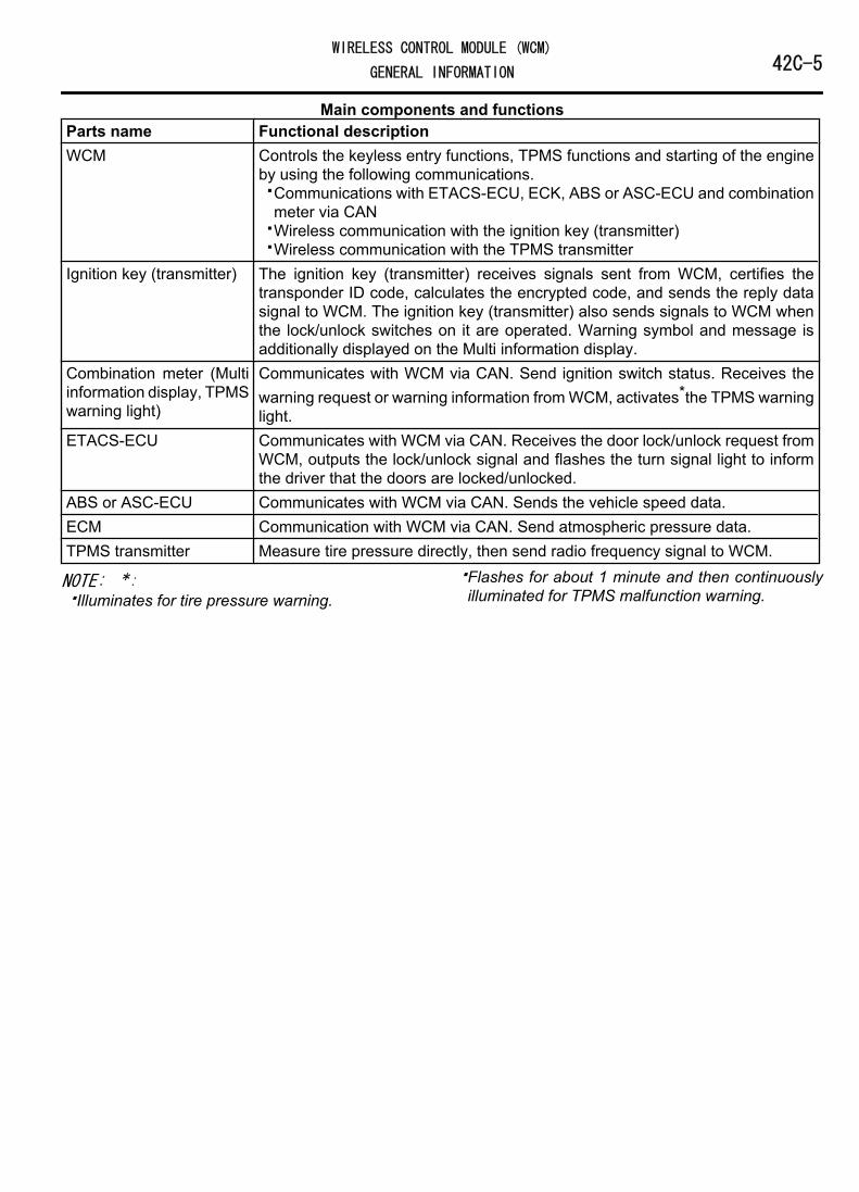
Main components and functionsParts name Functional descriptionWCM Controls the keyless entry functions, TPMS functions and starting of the engine
by using the following communications.⦆Communications with ETACS-ECU, ECK, ABS or ASC-ECU and combination
meter via CAN⦆Wireless communication with the ignition key (transmitter)⦆Wireless communication with the TPMS transmitter
Ignition key (transmitter) The ignition key (transmitter) receives signals sent from WCM, certifies thetransponder ID code, calculates the encrypted code, and sends the reply datasignal to WCM. The ignition key (transmitter) also sends signals to WCM whenthe lock/unlock switches on it are operated. Warning symbol and message isadditionally displayed on the Multi information display.
Combination meter (Multiinformation display, TPMSwarning light)
Communicates with WCM via CAN. Send ignition switch status. Receives thewarning request or warning information from WCM, activates*the TPMS warninglight.
ETACS-ECU Communicates with WCM via CAN. Receives the door lock/unlock request fromWCM, outputs the lock/unlock signal and flashes the turn signal light to informthe driver that the doors are locked/unlocked.
ABS or ASC-ECU Communicates with WCM via CAN. Sends the vehicle speed data.ECM Communication with WCM via CAN. Send atmospheric pressure data.TPMS transmitter Measure tire pressure directly, then send radio frequency signal to WCM.
NOTE: *:⦆Illuminates for tire pressure warning.
⦆Flashes for about 1 minute and then continuouslyilluminated for TPMS malfunction warning.
WIRELESS CONTROL MODULE (WCM)42C-5GENERAL INFORMATION
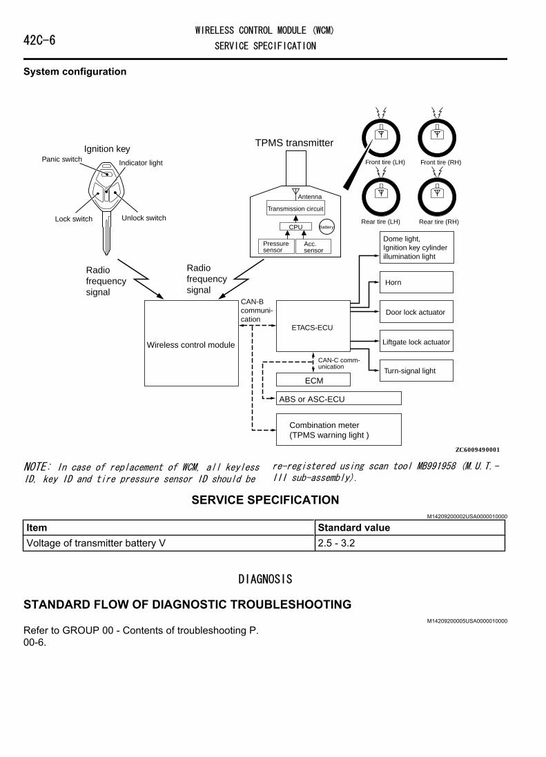
System configuration
ZC600949
Door lock actuator
ETACS-ECU
Turn-signal light
Wireless control module
ECM
Combination meter (TPMS warning light )
Lock switch Unlock switch
Indicator light
CAN-B communi- cation
CAN-C comm- unication
0001
Liftgate lock actuator
Ignition key
Radio frequency signal
Radio frequency signal
Front tire (LH) Front tire (RH)
Rear tire (LH) Rear tire (RH)
TPMS transmitter
CPU
Transmission circuit
Antenna
Pressure sensor
Acc. sensor
Battery
ABS or ASC-ECU
Dome light, Ignition key cylinder illumination light
Horn
Panic switch
NOTE: In case of replacement of WCM, all keylessID, key ID and tire pressure sensor ID should be
re-registered using scan tool MB991958 (M.U.T.-III sub-assembly).
SERVICE SPECIFICATIONM14209200002USA0000010000
Item Standard valueVoltage of transmitter battery V 2.5 - 3.2
DIAGNOSIS
STANDARD FLOW OF DIAGNOSTIC TROUBLESHOOTINGM14209200005USA0000010000
Refer to GROUP 00 - Contents of troubleshooting P.00-6.
42C-6WIRELESS CONTROL MODULE (WCM)
SERVICE SPECIFICATION

DIAGNOSTIC FUNCTIONM14209200006USA0000010000
HOW TO CONNECT THE SCAN TOOL (M.U.T.-III)Required Special Tools:⦆MB991958: Scan Tool (M.U.T.-III Sub Assembly)
⦆MB991824: Vehicle Communication Interface (V.C.I.)⦆MB991827: M.U.T.-III USB Cable⦆MB991910: M.U.T.-III Main Harness A (Vehicles with
CAN communication system)ZC501967AC404789
ZC5019680000
MB991824
MB991827
MB991910
Data linkconnector To prevent damage to scan tool MB991958, always turn the
ignition switch to the "LOCK" (OFF) position beforeconnecting or disconnecting scan tool MB991958.1.Ensure that the ignition switch is at the "LOCK" (OFF) position.2.Start up the personal computer.3.Connect special tool MB991827 to special tool MB991824 and
the personal computer.4.Connect special tool MB991910 to special tool MB991824.5.Connect special tool MB991910 to the data link connector.6.Turn the power switch of special tool MB991824 to the "ON"
position.
NOTE: When special tool MB991824 is energized, specialtool MB991824 indicator light will be illuminated in agreen color.
7.Start the M.U.T.-III system on the personal computer.
NOTE: Disconnecting scan tool MB991958 is the reverse ofthe connecting sequence, making sure that the ignitionswitch is at the "LOCK" (OFF) position.
HOW TO READ AND ERASE DIAGNOSTICTROUBLE CODESRequired Special Tools:⦆MB991958: Scan Tool (M.U.T.-III Sub Assembly)
⦆MB991824: Vehicle Communication Interface (V.C.I.)⦆MB991827: M.U.T.-III USB Cable⦆MB991910: M.U.T.-III Main Harness A (Vehicles with
CAN communication system)
To prevent damage to scan tool MB991958, always turn theignition switch to the "LOCK" (OFF) position beforeconnecting or disconnecting scan tool MB991958.NOTE: If the battery voltage is low, diagnostic troublecodes will not be set. Check the battery if scan toolMB991958 does not display.1.Connect scan tool MB991958 to the data link connector.
WIRELESS CONTROL MODULE (WCM)42C-7DIAGNOSIS

2.Turn the ignition switch to the "ON" position.3.Select "System select" from the start-up screen.4.Select "From 2006 MY" of "Model Year." When the "Vehicle
Information" is displayed, check the contents.5.Select "WCM" from "System List", and press the "OK" button.
NOTE: When the "Loading Option Setup" list is displayed,check the applicable item.
6.Select "Diagnostic Trouble Code."7.If a DTC is set, it is shown.8.Choose "Erase DTCs" to erase the DTC.
CHECK OF FREEZE FRAME DATAThe freeze frame data can be checked by using thescan tool (GROUP 00, How to Cope with IntermittentMalfunction P.00-15).
When detecting fault and storing the DTC, the ECUconnected to CAN bus line obtains the data before the
determination of the DTC and the data when the DTCis determined, and then stores the ECU status of thattime. By analyzing each data from scan tool, thetroubleshooting can be performed more efficiently.The displayed items are as the table below.
Display item listItem No. Item name Data item Unit
01 Odometer Total driving distance after the diagnosis code isgenerated
km*
02 Ignition cycle Number of times the ignition switch is turned "ON" or"LOCK (OFF)" after the past failure transition
Number ofcounts is
displayed.04 Current trouble
accumulative timeCumulative time for current malfunction of diagnosis
codemin
NOTE: *: If a failure occurs to both the ABS-ECU andETACS-ECU, 0000 km or FFFF km is displayed to the scan toolMB991958.
ID CODES REGISTRATION JUDGMENT TABLEM14209200007USA0000010000
Do not replace the engine control module (ECM)and WCM at the same time. When replacingseveral ECUs, always replace one ECU at a time,register the necessary IDs in it, and then replacethe next ECU.The transponder (a small transmitter) in the ignitionkey, WCM, and the ECM have their own ID codes
stored in them. When the cases listed in the tablebelow occur, the ID codes must be registered in theWCM or ECM again.
NOTE: Up to eight ignition keys (key ID andkeyless entry secret code) can be stored in thememory of WCM.
Item Operation contents andprocedure
Reference page for registrationcontents
When the ECM is replaced Registration of Key codes Key code registration (Refer toGROUP 00 - Precautions beforeService - How to Perform VINWriting P.00-26.)
42C-8WIRELESS CONTROL MODULE (WCM)
DIAGNOSIS

Item Operation contents andprocedure
Reference page for registrationcontents
When WCM is replaced 1. VIN programmed2. Register all the ignition keys
again.3. Register the keyless entry secret
code for all the ignition keysagain (keys with transmittersonly).
4. Register the TPMS transmitters
⦆Write the VIN (Refer to GROUP00 - Precautions before Service -How to Perform VIN Writing P.00-26).
⦆Registering keys and keylessIDs. (Refer to P.42C-85.)
⦆Registering tire pressure sensorID. (Refer to P.42C-92.)
When the ignition key is added asa single unit
1. Register all the ignition keysagain.
2. Register the keyless entry secretcode for all the ignition keysagain (keys with transmittersonly).
Key Registration and Keyless IDRegistration (Refer to P.42C-85)
When the ignition key is lost as asingle unit
1. Register all the ignition keysother than the lost one again.
2. Register the keyless entry secretcode for all ignition key otherthan the lost ignition key again
When the ignition key is replacedby the full service key set or thehandle lock service key set isreplaced by the piece.
1. Register all ignition keys againinput barcode No.
2. Register the keyless entry secretcode for all the ignition keysagain (set supply only).
Key Registration (Barcode No.) andKeyless ID Registration (Refer to P.42C-85)
When the blank key*is replacedby the door service key set orglove box service key set is addedby the piece.
Operation is not needed -
When TPMS transmitter isreplaced
Register the TPMS transmitter Registering tire pressure sensor ID.(Refer to P.42C-92.)
NOTE: *: Blank key (the key that can be used tolock/unlock the door, back door or glove box only)
SUPPLY UNIT LIST FOR INDIVIDUAL KEYIgnition key (with transmitter)
NOTE: Blank key (It is the key thatcomes with the door service key set andthe glove box service key set. It canonly be used for locking and unlocking,and it cannot start the engine.)
ZC6037530000ZC6044010001
Blank key
WIRELESS CONTROL MODULE (WCM)42C-9DIAGNOSIS
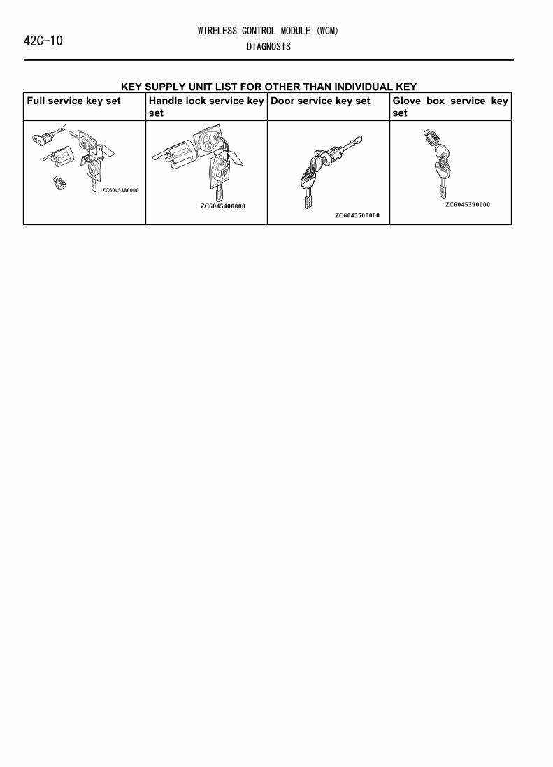
KEY SUPPLY UNIT LIST FOR OTHER THAN INDIVIDUAL KEYFull service key set Handle lock service key
setDoor service key set Glove box service key
set
ZC6045380000
ZC6045400000ZC6045500000
ZC6045390000
42C-10WIRELESS CONTROL MODULE (WCM)
DIAGNOSIS

Registration flow chart
ZC603749
YES
NO
4. Registration of keyless entry secret code
YES
YES
YES
NO
NO
NO
NOTE *: When WCM or TPMS transmitter is replaced. 0000
Start of registration
ECM is replaced.
1. Registration of Key Code
WCM is replaced.
2. Registration of VIN
Ignition key is replaced or added.
3. Registration of key ID (every one code)
3. Registration of key ID (Barcode No.)
Key is replaced by the full service key set or by the handle lock service
key set separately.
End of registration5. Registration of tire pressure sensor ID*
YES
NO
TPMS transmitter is replaced.
Caution:Do not replace the ECM and the WCM simultaneously. Always replace the ECU by ones when the multiple ECU is replaced, and then replace the next ECU after registering the necessary IDs.
DIAGNOSTIC TROUBLE CODE CHARTM14209200008USA0000010000
During diagnosis, a DTC associated with othersystem may be set when the ignition switch is
turned on with connector(s) disconnected. Oncompletion, check all systems for diagnostictrouble code(s). If DTC(s) are set, erase them all.
WIRELESS CONTROL MODULE (WCM)42C-11DIAGNOSIS

Diagnostic trouble codeNo.
Diagnostic item Referencepage
B1731 Engine control module communication timeout P.42C-13B1761 VIN code not programmed P.42C-15B1A08 Keyless/KOS key1 performance P.42C-16B1A09 Keyless/KOS key2 performanceB1A0A Keyless/KOS key3 performanceB1A0B Keyless/KOS key4 performanceB1A0C Keyless key 5 performanceB1A0D Keyless key 6 performanceB1A0E Keyless key 7 performanceB1A0F Keyless key 8 performanceB1A10 Keyless/KOS key 1 low battery P.42C-17B1A11 Keyless/KOS key 2 low batteryB1A12 Keyless/KOS key 3 low batteryB1A13 Keyless/KOS key 4 low batteryB1A14 Keyless key 5 low batteryB1A15 Keyless key 6 low batteryB1A16 Keyless key 7 low batteryB1A17 Keyless key 8 low batteryB1A24 Transponder ID not registered P.42C-18B1A25 Transponder ID unmatched P.42C-20B1A28 Engine control module authenticate error P.42C-22B1A35 Transponder read error P.42C-23B2101 IG SW start POS.circuit low P.42C-25B2102 IG SW start POS.circuit highB2204 Coding data mismatch P.42C-28B2206 VIN mismatch P.42C-30B2352 Antenna fail P.42C-31B2401 Keyless/KOS key ID not register P.42C-32B2416 ECU internal error P.42C-33C1608 EEPROM error P.42C-34C1900 No registration P.42C-35C1901 Vehicle speed information abnormality P.42C-37C1910 Transmitter low battery voltage abnormality 1 P.42C-39C1920 Transmitter low battery voltage abnormality 2C1930 Transmitter low battery voltage abnormality 3C1940 Transmitter low battery voltage abnormality 4C1911 Reception abnormality 1 P.42C-40C1921 Reception abnormality 2
42C-12WIRELESS CONTROL MODULE (WCM)
DIAGNOSIS
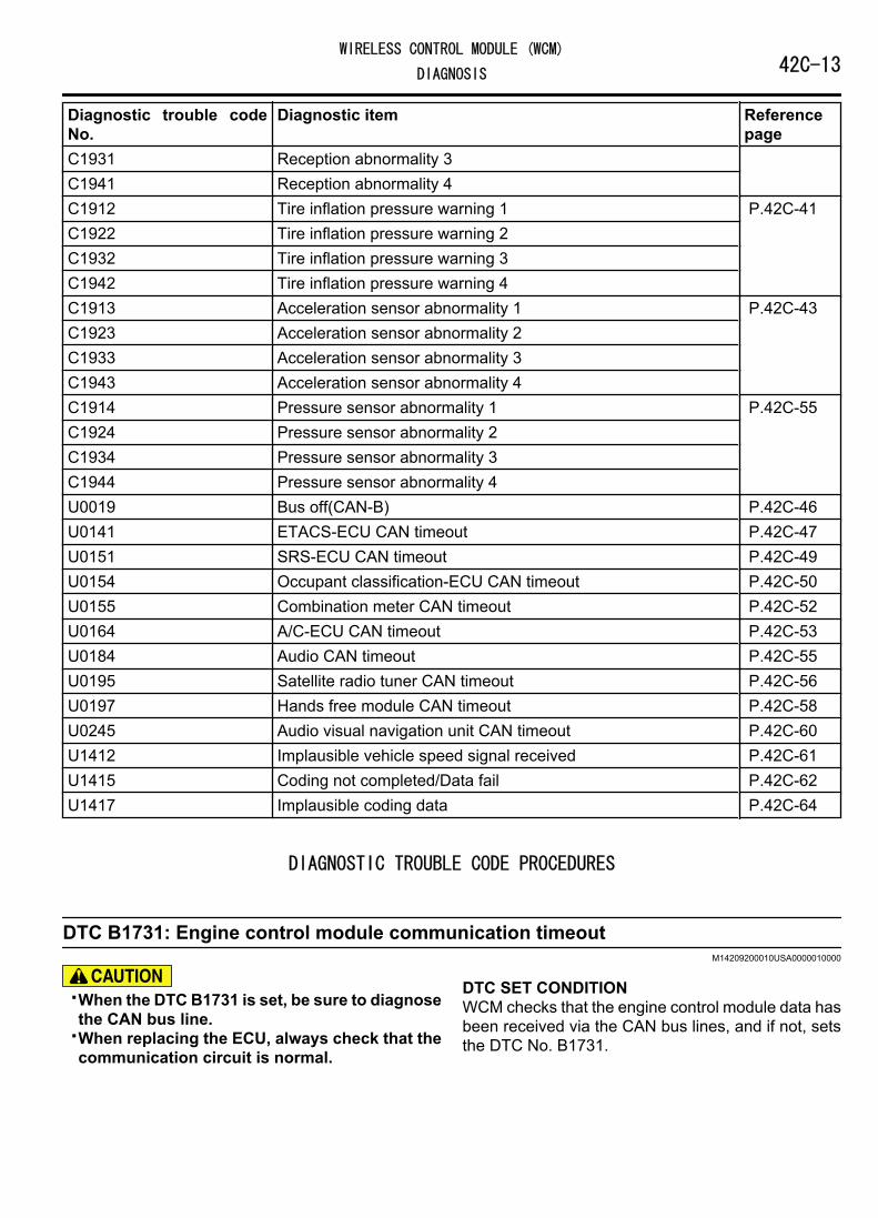
Diagnostic trouble codeNo.
Diagnostic item Referencepage
C1931 Reception abnormality 3C1941 Reception abnormality 4C1912 Tire inflation pressure warning 1 P.42C-41C1922 Tire inflation pressure warning 2C1932 Tire inflation pressure warning 3C1942 Tire inflation pressure warning 4C1913 Acceleration sensor abnormality 1 P.42C-43C1923 Acceleration sensor abnormality 2C1933 Acceleration sensor abnormality 3C1943 Acceleration sensor abnormality 4C1914 Pressure sensor abnormality 1 P.42C-55C1924 Pressure sensor abnormality 2C1934 Pressure sensor abnormality 3C1944 Pressure sensor abnormality 4U0019 Bus off(CAN-B) P.42C-46U0141 ETACS-ECU CAN timeout P.42C-47U0151 SRS-ECU CAN timeout P.42C-49U0154 Occupant classification-ECU CAN timeout P.42C-50U0155 Combination meter CAN timeout P.42C-52U0164 A/C-ECU CAN timeout P.42C-53U0184 Audio CAN timeout P.42C-55U0195 Satellite radio tuner CAN timeout P.42C-56U0197 Hands free module CAN timeout P.42C-58U0245 Audio visual navigation unit CAN timeout P.42C-60U1412 Implausible vehicle speed signal received P.42C-61U1415 Coding not completed/Data fail P.42C-62U1417 Implausible coding data P.42C-64
DIAGNOSTIC TROUBLE CODE PROCEDURES
DTC B1731: Engine control module communication timeoutM14209200010USA0000010000
⦆When the DTC B1731 is set, be sure to diagnosethe CAN bus line.
⦆When replacing the ECU, always check that thecommunication circuit is normal.
DTC SET CONDITIONWCM checks that the engine control module data hasbeen received via the CAN bus lines, and if not, setsthe DTC No. B1731.
WIRELESS CONTROL MODULE (WCM)42C-13DIAGNOSIS

TECHNICAL DESCRIPTION (COMMENT)If no data [ETACS transmits engine random numberdata to WCM via the CAN bus lines] is received fromthe engine control module via the CAN bus lines whenthe ignition switch is turned to ON position, it is judgedas abnormal.
TROUBLESHOOTING HINTS⦆Malfunction of CAN bus line⦆Malfunction of WCM⦆Malfunction of engine control module⦆Damaged wiring harness and connectors
DIAGNOSISRequired Special Tools:⦆MB991958: Scan Tool (M.U.T.-III Sub Assembly)
⦆MB991824: Vehicle Communication Interface (V.C.I.)⦆MB991827: M.U.T.-III USB Cable⦆MB991910: M.U.T.-III Main Harness A (Vehicles with
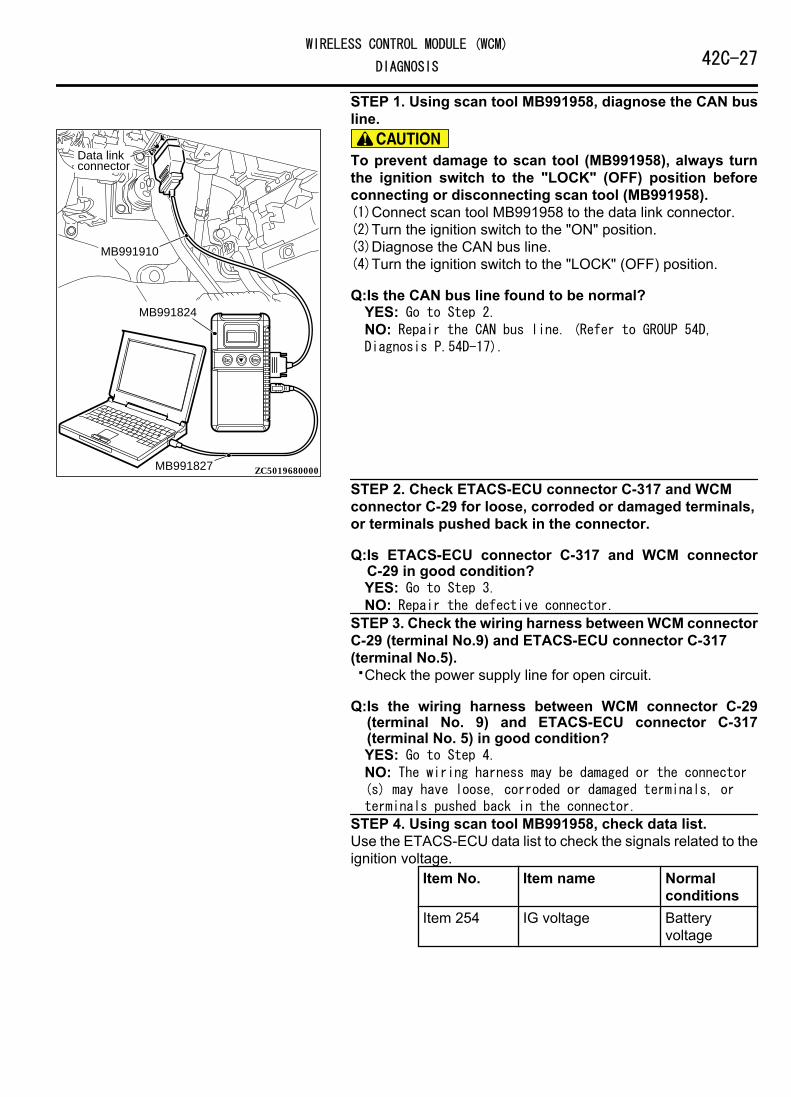
CAN communication system)STEP 1. Using scan tool MB991958, diagnose the CAN busline.
ZC501967AC404789
ZC5019680000
MB991824
MB991827
MB991910
Data linkconnector To prevent damage to scan tool (MB991958), always turn
the ignition switch to the "LOCK" (OFF) position beforeconnecting or disconnecting scan tool (MB991958).(1)Connect scan tool MB991958 to the data link connector.(2)Turn the ignition switch to the "ON" position.(3)Diagnose the CAN bus line.(4)Turn the ignition switch to the "LOCK" (OFF) position.
Q:Is the CAN bus line found to be normal?YES: Go to Step 2.NO: Repair the CAN bus line. (Refer to GROUP 54D,Diagnosis P.54D-17).
STEP 2. Using scan tool MB991958, read the engine controlmodule diagnostic trouble code.Check again if the DTC is set to the engine control module.
Q:Is the DTC set?YES: Troubleshoot the MFI system (Refer to GROUP 13Ab,Diagnostic trouble code chart P.13Ab-44).NO: Go to Step 3.
STEP 3. Recheck for diagnostic trouble code.Check again if the DTC is set to the WCM.(1)Erase the DTC.(2)Turn the ignition switch from "LOCK" (OFF) position to "ON"
position.(3)Check if DTC is set.
42C-14WIRELESS CONTROL MODULE (WCM)
DIAGNOSIS

(4)Turn the ignition switch to the "LOCK" (OFF) position.
Q:Is the DTC set?YES: Replace WCM and register the ID codes. (Refer to P.42C-8.)NO: The trouble can be an intermittent malfunction (Referto GROUP 00 - How to use Troubleshooting/inspectionService Points - How to Cope with IntermittentMalfunction P.00-15).
DTC B1761: VIN code not programmedM14209200011USA0000010000
⦆When the DTC No. B1761 is set, be sure todiagnose the CAN bus line.
⦆When replacing the ECU, always check that thecommunication circuit is normal.
DTC SET CONDITIONWCM sets DTC B1761 when no VIN is recorded in it.
TECHNICAL DESCRIPTION (COMMENT)WCM determines that the abnormality is presentwhen no VIN is recorded in it.
TROUBLESHOOTING HINTS⦆VIN not programmed⦆Malfunction of the WCM
DIAGNOSISRequired Special Tools:⦆MB991958: Scan Tool (M.U.T.-III Sub Assembly)
⦆MB991824: Vehicle Communication Interface (V.C.I.)⦆MB991827: M.U.T.-III USB Cable⦆MB991910: M.U.T.-III Main Harness A (Vehicles with
CAN communication system)
WIRELESS CONTROL MODULE (WCM)42C-15DIAGNOSIS

STEP 1. Using scan tool MB991958, diagnose the CAN busline.
ZC501967AC404789
ZC5019680000
MB991824
MB991827
MB991910
Data linkconnector To prevent damage to scan tool (MB991958), always turn
the ignition switch to the "LOCK" (OFF) position beforeconnecting or disconnecting scan tool (MB991958).(1)Connect scan tool MB991958 to the data link connector.(2)Turn the ignition switch to the "ON" position.(3)Diagnose the CAN bus line.(4)Turn the ignition switch to the "LOCK" (OFF) position.
Q:Is the CAN bus line found to be normal?YES: Go to Step 2.NO: Repair the CAN bus line. (Refer to GROUP 54D,Diagnosis P.54D-17).
STEP 2. Register the VIN and recheck the diagnostic troublecode.Register VIN in WCM (Refer to GROUP 00 - How to PerformVehicle Identification Number (VIN) Writing P.00-26) andrecheck if the DTC is set.(1)Turn the ignition switch from the "LOCK" (OFF) position to
the "ON" position.(2)Check if DTC is set.(3)Turn the ignition switch to the "LOCK" (OFF) position.
Q:Is the DTC set?YES: Replace WCM and register the ID codes. (Refer to P.42C-8.)NO: The procedure is complete.
Code No.B1A08 Keyless/KOS key1 performanceM14209200012USA0000010000
Code No.B1A09 Keyless/KOS key2 performanceCode No.B1A0A Keyless/KOS key3 performanceCode No.B1A0B Keyless/KOS key4 performanceCode No.B1A0C Keyless key 5 performanceCode No.B1A0D Keyless key 6 performanceCode No.B1A0E Keyless key 7 performanceCode No.B1A0F Keyless key 8 performance
When replacing the ECU, always check that thecommunication circuit is normal.
DIAGNOSTIC FUNCTIONThe door locking/unlocking code is automaticallyupdated every time the doors are locked (rollingcode). WCM stores diagnostic trouble code No.B1A08, B1A09, B1A0A, B1A0B, B1A0C, B1A0D,B1A0E, or B1A0F when it receives wrong signal(rolling code out of synchronization) from thetransmitter.
42C-16WIRELESS CONTROL MODULE (WCM)
DIAGNOSIS

JUDGEMENT CRITERIA⦆B1A08: WCM determines that the abnormality is
present when the rolling code received from thetransmitter 1 (the first transmitter registered inWCM) greatly differs from the rolling code stored inWCM.
⦆B1A09: WCM determines that the abnormality ispresent when the rolling code received from thetransmitter 2 (the second transmitter registered inWCM) greatly differs from the rolling code stored inWCM.
⦆B1A0A: WCM determines that the abnormality ispresent when the rolling code received from thetransmitter 3 (the third transmitter registered inWCM) greatly differs from the rolling code stored inWCM.
⦆B1A0B: WCM determines that the abnormality ispresent when the rolling code received from thetransmitter 4 (the fourth transmitter registered inWCM) greatly differs from the rolling code stored inWCM.
⦆B1A0C: WCM determines that the abnormality ispresent when the rolling code received from thetransmitter 5 (the fifth transmitter registered inWCM) greatly differs from the rolling code stored inWCM.
⦆B1A0D: WCM determines that the abnormality ispresent when the rolling code received from thetransmitter 6 (the sixth transmitter registered inWCM) greatly differs from the rolling code stored inWCM.
⦆B1A0E: WCM determines that the abnormality ispresent when the rolling code received from thetransmitter 7 (the seventh transmitter registered inWCM) greatly differs from the rolling code stored inWCM.
⦆B1A0F: WCM determines that the abnormality ispresent when the rolling code received from thetransmitter 8 (the eighth transmitter registered inWCM) greatly differs from the rolling code stored inWCM.
PROBABLE CAUSES⦆Rolling code out of synchronization⦆Malfunction of the transmitter⦆Malfunction of the WCM
DIAGNOSTIC PROCEDURE
STEP 1. Synchronize the rolling code and recheckthe diagnostic trouble code.(1)Synchronize the rolling code. Use either way to
synchronize the rolling code:⦆Push the transmitter switches twice or more.⦆Resister the keyless entry secret code of. (Refer
to P.00-15.)
NOTE: *: Name of the signals to beregistered.
(2)Recheck if the diagnostic trouble code is set.Erase the diagnostic trouble code.Push the lock switch or unlock switch oftransmitter.Check if the diagnostic trouble code is set.
Q:Is the diagnostic trouble code set?YES: Go to Step 2.NO: The procedure is complete.
STEP 2. Check whether the diagnostic troublecode is reset.Replace the transmitter with a new one, register theencrypted code and the keyless entry secret code(Refer to P.00-15.), and recheck if the diagnostictrouble code is set.(1)Erase the diagnostic trouble code.(2)Push the lock switch or unlock switch of
transmitter.(3)Check if the diagnostic trouble code is set.
Q:Is the diagnostic trouble code set?YES: Replace WCM and register the ID codes.(Refer to P.00-15.)NO: The procedure is complete.
Code No.B1A10 Keyless/KOS key 1 low batteryM14209200013USA0000010000
Code No.B1A11 Keyless/KOS key 2 low batteryCode No.B1A12 Keyless/KOS key 3 low batteryCode No.B1A13 Keyless/KOS key 4 low batteryCode No.B1A14 Keyless key 5 low batteryCode No.B1A15 Keyless key 6 low batteryCode No.B1A16 Keyless key 7 low battery
Code No.B1A17 Keyless key 8 low battery
When replacing the ECU, always check that thecommunication circuit is normal.
WIRELESS CONTROL MODULE (WCM)42C-17DIAGNOSIS

DIAGNOSTIC FUNCTIONWCM sets the diagnostic trouble code No. B1A10,B1A11, B1A12, B1A13, B1A14, B1A15, B1A16, orB1A17 when it receives low battery voltage signalfrom the transmitter.
JUDGEMENT CRITERIA⦆B1A10: WCM determines that the abnormality is
present when it receives low battery voltage signalfrom the transmitter 1 (the first transmitterregistered in WCM) five consecutive times.
⦆B1A11: WCM determines that the abnormality ispresent when it receives low battery voltage signalfrom the transmitter 2 (the second transmitterregistered in WCM) five consecutive times.
⦆B1A12: WCM determines that the abnormality ispresent when it receives low battery voltage signalfrom the transmitter 3 (the third transmitterregistered in WCM) five consecutive times.
⦆B1A13: WCM determines that the abnormality ispresent when it receives low battery voltage signalfrom the transmitter 4 (the fourth transmitterregistered in WCM) five consecutive times.
⦆B1A14: WCM determines that the abnormality ispresent when it receives low battery voltage signalfrom the transmitter 5 (the fifth transmitterregistered in WCM) five consecutive times.
⦆B1A15: WCM determines that the abnormality ispresent when it receives low battery voltage signalfrom the transmitter 6 (the sixth transmitterregistered in WCM) five consecutive times.
⦆B1A16: WCM determines that the abnormality ispresent when it receives low battery voltage signalfrom the transmitter 7 (the seventh transmitterregistered in WCM) five consecutive times.
⦆B1A17: WCM determines that the abnormality ispresent when it receives low battery voltage signal
from the transmitter 8 (the eighth transmitterregistered in WCM) five consecutive times.
PROBABLE CAUSES⦆Battery failure in the transmitter⦆Malfunction of the transmitter⦆Malfunction of WCM
DIAGNOSTIC PROCEDURE
STEP 1. Replace the battery in the transmitter andrecheck the diagnostic trouble code.Replace the battery in the transmitter with a new one,and recheck if the diagnostic trouble code is set.(1)Replace the battery in the transmitter.(2)Use the transmitter to lock/unlock the doors.(3)Check if the diagnostic trouble code is set.
Q:Is the diagnostic trouble code set?YES: Go to Step 2.NO: The procedure is complete. (Dischargedbattery)
STEP 2. Replace the transmitter and recheck thediagnostic trouble code.Replace the transmitter with a new one, register theencrypted code and the keyless entry secret code(Refer to P.00-15.), and recheck if the diagnostictrouble code is set.(1)Use the transmitter to lock/unlock the doors.(2)Check if the diagnostic trouble code is set.
Q:Is the diagnostic trouble code set?YES: Replace WCM and register the ID codes.(Refer to P.00-15.)NO: The procedure is complete.
DTC B1A24: Transponder ID not registeredM14209200014USA0000010000
DTC SET CONDITIONWCM sets DTC B1A24 when the encrypted code wasnot registered in it.
TECHNICAL DESCRIPTION (COMMENT)WCM determines that the abnormality is present, if theignition key's encrypted code is not registered in WCMwhen the ignition switch is turned ON.
TROUBLESHOOTING HINTS⦆Encrypted code not registered⦆Malfunction of the ignition key⦆Malfunction of WCM
42C-18WIRELESS CONTROL MODULE (WCM)
DIAGNOSIS

DIAGNOSISRequired Special Tools:⦆MB991958: Scan Tool (M.U.T.-III Sub Assembly)
⦆MB991824: Vehicle Communication Interface (V.C.I.)⦆MB991827: M.U.T.-III USB Cable⦆MB991910: M.U.T.-III Main Harness A (Vehicles with
CAN communication system)STEP 1. Using scan tool MB991958, diagnose the CAN busline.
ZC501967AC404789
ZC5019680000
MB991824
MB991827
MB991910
Data linkconnector To prevent damage to scan tool (MB991958), always turn
the ignition switch to the "LOCK" (OFF) position beforeconnecting or disconnecting scan tool (MB991958).(1)Connect scan tool MB991958 to the data link connector.(2)Turn the ignition switch to the "ON" position.(3)Diagnose the CAN bus line.(4)Turn the ignition switch to the "LOCK" (OFF) position.
Q:Is the CAN bus line found to be normal?YES: Go to Step 2.NO: Repair the CAN bus line. (Refer to GROUP 54D,Diagnosis P.54D-17).
STEP 2. Register the encrypted code and recheck thediagnostic trouble code.Register the encrypted code of the ignition key (refer to P.42C-85), and recheck if the DTC is set.(1)Turn the ignition switch from the "LOCK" (OFF) position to
the "ON" position.(2)Check if the DTC is set.
Q:Is the DTC set?YES: Go to Step 3.NO: The procedure is complete.
STEP 3. Replace the ignition key and recheck the diagnostictrouble code.Replace the ignition key with a new one, register the encryptedcode of the new key, (refer to P.42C-85), and recheck if theDTC is set.(1)Turn the ignition switch from the "LOCK" (OFF) position to
the "ON" position.(2)Check if the DTC is set.
WIRELESS CONTROL MODULE (WCM)42C-19DIAGNOSIS

Q:Is the DTC set?YES: Replace WCM and register the ID codes. (Refer to P.42C-8.)NO: The procedure is complete.
DTC B1A25: Transponder ID unmatchedM14209200015USA0000010000
DTC SET CONDITIONWCM sets the DTC B1A25 when the receivedtransponder ID is different from the one registered init.
TECHNICAL DESCRIPTION (COMMENT)WCM determines that the abnormality is present, if theencrypted code for the ignition key does not match theone registered in WCM when the ignition switch isturned ON.
TROUBLESHOOTING HINTS⦆Malfunction of the ignition key⦆Malfunction of WCM⦆Key not registered⦆WCM not registered⦆Key is registered to another vehicle
DIAGNOSISRequired Special Tools:⦆MB991958: Scan Tool (M.U.T.-III Sub Assembly)
⦆MB991824: Vehicle Communication Interface (V.C.I.)⦆MB991827: M.U.T.-III USB Cable⦆MB991910: M.U.T.-III Main Harness A (Vehicles with
CAN communication system)
42C-20WIRELESS CONTROL MODULE (WCM)
DIAGNOSIS

STEP 1. Using scan tool MB991958, diagnose the CAN busline.
ZC501967AC404789
ZC5019680000
MB991824
MB991827
MB991910
Data linkconnector To prevent damage to scan tool (MB991958), always turn
the ignition switch to the "LOCK" (OFF) position beforeconnecting or disconnecting scan tool (MB991958).(1)Connect scan tool MB991958 to the data link connector.(2)Turn the ignition switch to the "ON" position.(3)Diagnose the CAN bus line.(4)Turn the ignition switch to the "LOCK" (OFF) position.
Q:Is the CAN bus line found to be normal?YES: Go to Step 2.NO: Repair the CAN bus line. (Refer to GROUP 54D,Diagnosis P.54D-17).
STEP 2. Register the encrypted code and recheck thediagnostic trouble code.Register the encrypted code of the ignition key (refer to P.42C-85), and recheck if the DTC is set.(1)Turn the ignition switch from the "LOCK" (OFF) position to
the "ON" position.(2)Check if the DTC is set.
Q:Is the DTC set?YES: Go to Step 3.NO: The procedure is complete.
STEP 3. Replace the ignition key and recheck the diagnostictrouble code.Replace the ignition key with a new one, register the encryptedcode of the new key, (refer to P.42C-8), and recheck if the DTCis set.(1)Turn the ignition switch from the "LOCK" (OFF) position to
the "ON" position.(2)Check if the DTC is set.
Q:Is the DTC set?YES: Replace WCM and register the ID codes. (Refer to P.42C-8.)NO: The procedure is complete.
WIRELESS CONTROL MODULE (WCM)42C-21DIAGNOSIS

DTC B1A28: Engine control module authenticate errorM14209200016USA0000010000
⦆When the DTC B1A28 is set, be sure to diagnosethe CAN bus line.
⦆When replacing the ECU, always check that thecommunication circuit is normal.
DTC SET CONDITIONWCM sets DTC B1A28 when the ignition keycertification result and the engine control modulestarting condition do not match.
TECHNICAL DESCRIPTION (COMMENT)WCM determines that the abnormality is present, if thekey certification result and the engine control module
starting condition do not match after the engine startpermission communication is completed.
TROUBLESHOOTING HINTS⦆Malfunction of WCM⦆Engine control module malfunction⦆VIN registered in engine control module unmatched
DIAGNOSISRequired Special Tools:⦆MB991958: Scan Tool (M.U.T.-III Sub Assembly)
⦆MB991824: Vehicle Communication Interface (V.C.I.)⦆MB991827: M.U.T.-III USB Cable⦆MB991910: M.U.T.-III Main Harness A (Vehicles with
CAN communication system)STEP 1. Using scan tool MB991958, diagnose the CAN busline.
ZC501967AC404789
ZC5019680000
MB991824
MB991827
MB991910
Data linkconnector To prevent damage to scan tool (MB991958), always turn
the ignition switch to the "LOCK" (OFF) position beforeconnecting or disconnecting scan tool (MB991958).(1)Connect scan tool MB991958 to the data link connector.(2)Turn the ignition switch to the "ON" position.(3)Diagnose the CAN bus line.(4)Turn the ignition switch to the "LOCK" (OFF) position.
Q:Is the CAN bus line found to be normal?YES: Go to Step 2.NO: Repair the CAN bus line. (Refer to GROUP 54D,Diagnosis P.54D-17).
42C-22WIRELESS CONTROL MODULE (WCM)
DIAGNOSIS

STEP 2. Check if VIN registered in the engine controlmodule matches with the vehicle's VIN.Check if VIN registered in the engine control module matcheswith the vehicle's VIN.
Q:Does the VIN registered in the engine control modulematch the vehicle's VIN?YES: Go to Step 3.NO: Replace the engine ECU and record VIN (Refer to GROUP00 - How to Perform Vehicle Identification Number (VIN)Writing P.00-26). Record VIN and go to Step 3.
STEP 3. Recheck for diagnostic trouble code.Check again if the DTC is set to the WCM.(1)Turn the ignition switch from the "LOCK" (OFF) position to
the "ON" position.(2)Check if the DTC is set.
Q:Is the DTC set?YES: Replace WCM and register the ID codes. (Refer to P.42C-8.)NO: Intermittent malfunction is suspected. (Refer toGROUP 00 - How to Use Troubleshooting/Inspection ServicePoints - How to Deal with Intermittent Malfunction P.00-15.)
DTC B1A35: Transponder read errorM14209200017USA0000010000
⦆When DTC B1A35 is set, be sure to diagnose theCAN bus line.
⦆When replacing the ECU, always check that thecommunication circuit is normal.
DTC SET CONDITIONWCM sets DTC B1A35 when it cannot receive datafrom the transponder.
TECHNICAL DESCRIPTION (COMMENT)WCM determines that the abnormality is present, if itcannot receive the encrypted code for the ignition keywhen the ignition switch is turned ON.
TROUBLESHOOTING HINTS⦆Malfunction of the ignition key⦆Malfunction of WCM⦆Interference of the encrypted code
DIAGNOSISRequired Special Tools:⦆MB991958: Scan Tool (M.U.T.-III Sub Assembly)
⦆MB991824: Vehicle Communication Interface (V.C.I.)⦆MB991827: M.U.T.-III USB Cable⦆MB991910: M.U.T.-III Main Harness A (Vehicles with
CAN communication system)
WIRELESS CONTROL MODULE (WCM)42C-23DIAGNOSIS

STEP 1. Using scan tool MB991958, diagnose the CAN busline.
ZC501967AC404789
ZC5019680000
MB991824
MB991827
MB991910
Data linkconnector To prevent damage to scan tool (MB991958), always turn
the ignition switch to the "LOCK" (OFF) position beforeconnecting or disconnecting scan tool (MB991958).(1)Connect scan tool MB991958 to the data link connector.(2)Turn the ignition switch to the "ON" position.(3)Diagnose the CAN bus line.(4)Turn the ignition switch to the "LOCK" (OFF) position.
Q:Is the CAN bus line found to be normal?YES: Go to Step 2.NO: Repair the CAN bus line. (Refer to GROUP 54D,Diagnosis P.54D-17).
STEP 2. Check the ignition key inserted in the key cylinderfor interference.
Q:Are there other ignition keys or anything that interfereswith the communication (things that generate radiowaves such as magnets or air-cleaning device that has apower plug) near the ignition key inserted in the keycylinder?YES: Move away or remove other ignition keys or anythingthat interferes with the communication, and go to Step 3.NO: Go to Step 3.
STEP 3. Recheck for diagnostic trouble code.Check again if the DTC is set to the WCM.(1)Turn the ignition switch from the "LOCK" (OFF) position to
the "ON" position.(2)Check if the DTC is set.
Q:Is the DTC set?YES: Go to Step 4.NO: The procedure is complete.
STEP 4. Replace the ignition key and recheck the diagnostictrouble code.Replace the ignition key by which the DTC is set with a new one,register the encrypted code of the new key, (refer to P.42C-8),and recheck if the DTC is set.(1)Turn the ignition switch from the "LOCK" (OFF) position to
the "ON" position.(2)Check if the DTC is set.
Q:Is the diagnostic trouble code set?
42C-24WIRELESS CONTROL MODULE (WCM)
DIAGNOSIS

YES: Replace WCM and register the ID codes. (Refer to P.42C-8.)NO: The procedure is complete.
DTC B2101: IG SW start POS.circuit lowDTC B2102: IG SW start POS.circuit high
M14209200018USA0000010000
⦆If DTC B2101 or B2102 is set, be sure todiagnose the CAN bus line.
⦆Before replacing the ECU, ensure that thecommunication circuit is normal.
WCM Communication Circuit
34FUSIBLELINK
IGNITIONSWITCH (IG1)
ETACS-ECU
IGNITION KEYRING ANTENNA ENCRYPTED CODE
TRANSPONDER
IG1RELAY
WCM
WIRELESS CONTROL MODULE (WCM)42C-25DIAGNOSIS

ZC6008780006
Connector: C-317
ZC6008750033
Connector: C-29
DTC SET CONDITIONWCM sets DTC B2101 or B2012 when the actual stateof the ignition switch and the ignition switch positioninformation received from ETACS-ECU via CAN donot match.
TECHNICAL DESCRIPTION (COMMENT)WCM determines that the abnormality is present, if ithas detected discrepancy in the ignition switch levelshown below ten consecutive times when WCM hasreceived the CAN message (ignition switch positioninformation) from ETACS-ECU with the ignition switchturned to the ON or START position.
B2101
⦆Status of ignition switch: OFF position⦆Ignition switch position information from the
ETACS-ECU: ON
B2102⦆Status of ignition switch: ON position⦆Ignition switch position information from the
ETACS-ECU: OFF
TROUBLESHOOTING HINTS⦆Malfunction of CAN bus line⦆Malfunction of the WCM⦆Malfunction of the ignition switch⦆Damaged wiring harness and connectors⦆Malfunction of ETACS-ECU
DIAGNOSISRequired Special Tools:⦆MB991958: Scan Tool (M.U.T.-III Sub Assembly)
⦆MB991824: Vehicle Communication Interface (V.C.I.)⦆MB991827: M.U.T.-III USB Cable⦆MB991910: M.U.T.-III Main Harness A (Vehicles with
CAN communication system)
42C-26WIRELESS CONTROL MODULE (WCM)
DIAGNOSIS
STEP 1. Using scan tool MB991958, diagnose the CAN busline.
ZC501967AC404789
ZC5019680000
MB991824
MB991827
MB991910
Data linkconnector To prevent damage to scan tool (MB991958), always turn
the ignition switch to the "LOCK" (OFF) position beforeconnecting or disconnecting scan tool (MB991958).(1)Connect scan tool MB991958 to the data link connector.(2)Turn the ignition switch to the "ON" position.(3)Diagnose the CAN bus line.(4)Turn the ignition switch to the "LOCK" (OFF) position.
Q:Is the CAN bus line found to be normal?YES: Go to Step 2.NO: Repair the CAN bus line. (Refer to GROUP 54D,Diagnosis P.54D-17).
STEP 2. Check ETACS-ECU connector C-317 and WCMconnector C-29 for loose, corroded or damaged terminals,or terminals pushed back in the connector.
Q:Is ETACS-ECU connector C-317 and WCM connectorC-29 in good condition?YES: Go to Step 3.NO: Repair the defective connector.
STEP 3. Check the wiring harness between WCM connectorC-29 (terminal No.9) and ETACS-ECU connector C-317(terminal No.5).⦆Check the power supply line for open circuit.
Q:Is the wiring harness between WCM connector C-29(terminal No. 9) and ETACS-ECU connector C-317(terminal No. 5) in good condition?YES: Go to Step 4.NO: The wiring harness may be damaged or the connector(s) may have loose, corroded or damaged terminals, orterminals pushed back in the connector.
STEP 4. Using scan tool MB991958, check data list.Use the ETACS-ECU data list to check the signals related to theignition voltage.
Item No. Item name Normalconditions
Item 254 IG voltage Batteryvoltage
WIRELESS CONTROL MODULE (WCM)42C-27DIAGNOSIS

Q:Does scan tool MB991958 display the item "IG voltage"as normal condition?YES: Go to Step 5.NO: Diagnose the ETACS-ECU. Refer to GROUP 54Ad,Diagnosis P.54Ad-8.
STEP 5. Recheck for diagnostic trouble code.Check again if the DTC is set to the WCM.(1)Erase the DTC.(2)Turn the ignition switch from "LOCK" (OFF) position to "ON"
position.(3)Check if DTC is set.(4)Turn the ignition switch to the "LOCK" (OFF) position.
Q:Is the DTC set?YES: Replace WCM and register the ID codes. (Refer to P.42C-8.)NO: The trouble can be an intermittent malfunction (Referto GROUP 00 - How to use Troubleshooting/inspectionService Points - How to Cope with IntermittentMalfunction P.00-15).
DTC B2204: Coding data mismatchM14209200019USA0000010000
DTC SET CONDITIONWCM sets the DTC B2204 when the vehicleinformation data on the CAN line does not match thevehicle information data registered in WCM.
TECHNICAL DESCRIPTION (COMMENT)WCM determines that the abnormality is presentwhen the vehicle information registered in it does notmatch the vehicle information data.
TROUBLESHOOTING HINTS⦆Malfunction of WCM⦆Malfunction of ETACS-ECU
DIAGNOSTIC PROCEDURE
42C-28WIRELESS CONTROL MODULE (WCM)
DIAGNOSIS

STEP 1. Using scan tool MB991958, diagnose the CAN busline.
ZC501967AC404789
ZC5019680000
MB991824
MB991827
MB991910
Data linkconnector To prevent damage to scan tool (MB991958), always turn
the ignition switch to the "LOCK" (OFF) position beforeconnecting or disconnecting scan tool (MB991958).(1)Connect scan tool MB991958 to the data link connector.(2)Turn the ignition switch to the "ON" position.(3)Diagnose the CAN bus line.(4)Turn the ignition switch to the "LOCK" (OFF) position.
Q:Is the CAN bus line found to be normal?YES: Go to Step 2.NO: Repair the CAN bus line. (Refer to GROUP 54D,Diagnosis P.54D-17).
STEP 2. Using scan tool MB991958, read the ETACS-ECUdiagnostic trouble codeCheck again if the DTC is set to the ETACS-ECU.
Q:Is the DTC set?YES: Troubleshoot the ETACS. (Refer to GROUP 54Ad,Diagnosis P.54Ad-8.)NO: Go to Step 3.
STEP 3. Recheck for diagnostic trouble code.Check again if the DTC is set to the WCM.(1)Erase the DTC.(2)Turn the ignition switch from "LOCK" (OFF) position to "ON"
position.(3)Check if DTC is set.(4)Turn the ignition switch to the "LOCK" (OFF) position.
Q:Is the DTC set?YES: Replace WCM and register the ID codes. (Refer to P.42C-8.)NO: The trouble can be an intermittent malfunction (Referto GROUP 00 - How to use Troubleshooting/inspectionService Points - How to Cope with IntermittentMalfunction P.00-15).
WIRELESS CONTROL MODULE (WCM)42C-29DIAGNOSIS

DTC B2206: VIN mismatchM14209200020USA0000010000
DTC SET CONDITIONWCM sets DTC B2206 when chassis numberregistered in it and the VIN that has been transmittedon the CAN bus do not match.
TECHNICAL DESCRIPTION (COMMENT)WCM determines that the abnormality is presentwhen VIN registered in it and the one that has beentransmitted on the CAN bus do not match.
TROUBLESHOOTING HINTS⦆Malfunction of WCM⦆VIN registered in engine ECU unmatched⦆WCM being registered to another vehicle
DIAGNOSISRequired Special Tools:⦆MB991958: Scan Tool (M.U.T.-III Sub Assembly)
⦆MB991824: Vehicle Communication Interface (V.C.I.)⦆MB991827: M.U.T.-III USB Cable⦆MB991910: M.U.T.-III Main Harness A (Vehicles with
CAN communication system)STEP 1. Check the VIN registered in engine control module.Check if VIN registered in the engine control module matcheswith the vehicle's VIN.
Q:Do VIN registered in the engine control module and thevehicle's VIN match?YES: Go to Step 2.NO: Replace the engine control module and record VIN(Refer to GROUP 00 - How to Perform Vehicle IdentificationNumber (VIN) Writing P.00-26). Record VIN and go to Step2.
STEP 2. Recheck for diagnostic trouble code.Check again if the DTC is set to the WCM.
42C-30WIRELESS CONTROL MODULE (WCM)
DIAGNOSIS

ZC501967AC404789
ZC5019680000
MB991824
MB991827
MB991910
Data linkconnector To prevent damage to scan tool (MB991958), always turn
the ignition switch to the "LOCK" (OFF) position beforeconnecting or disconnecting scan tool (MB991958).(1)Connect scan tool MB991958 to the data link connector.(2)Turn the ignition switch to the "ON" position.(3)Check if the DTC is set.
Q:Is the DTC set?YES: Replace WCM and register the ID codes. (Refer to P.42C-8.)NO: The procedure is complete.
DTC B2352: Antenna failM14209200021USA0000010000
DTC SET CONDITIONWCM sets the DTC B2352 when open or short circuitto the ground in the antenna is detected.
TECHNICAL DESCRIPTION (COMMENT)When the ignition switch is turned ON, WCM transmitssignal to the antenna. When the antenna is found
faulty, WCM determines that the abnormality ispresent.
TROUBLESHOOTING HINTMalfunction of WCM (Open circuit in antenna)
DIAGNOSISRequired Special Tools:⦆MB991958: Scan Tool (M.U.T.-III Sub Assembly)
⦆MB991824: Vehicle Communication Interface (V.C.I.)⦆MB991827: M.U.T.-III USB Cable⦆MB991910: M.U.T.-III Main Harness A (Vehicles with
CAN communication system)Recheck for diagnostic trouble code.Check again if the DTC is set to the WCM.
WIRELESS CONTROL MODULE (WCM)42C-31DIAGNOSIS

ZC501967AC404789
ZC5019680000
MB991824
MB991827
MB991910
Data linkconnector To prevent damage to scan tool (MB991958), always turn
the ignition switch to the "LOCK" (OFF) position beforeconnecting or disconnecting scan tool (MB991958).(1)Connect scan tool MB991958 to the data link connector.
Erase the DTC.(2)Turn the ignition switch from "LOCK" (OFF) position to "ON"
position.(3)Check if DTC is set.(4)Turn the ignition switch to the "LOCK" (OFF) position.
Q:Is the DTC set?YES: Replace WCM and register the ID codes. (Refer to P.42C-8.)NO: The procedure is complete.
DTC B2401: Keyless/KOS key ID not registerM14209200022USA0000010000
⦆If the DTC B2401 is set, be sure to diagnose theCAN bus line.
⦆When replacing the ECU, always check that thecommunication circuit is normal.
DTC SET CONDITIONWCM sets the DTC B2401 when no transmitter isregistered in it.
TECHNICAL DESCRIPTION (COMMENT)WCM determines that the abnormality is presentwhen the number of the transmitters registered in it is0.
TROUBLESHOOTING HINTS⦆Failure of transmitter registration process⦆Malfunction of WCM
DIAGNOSISRequired Special Tools:⦆MB991958: Scan Tool (M.U.T.-III Sub Assembly)
⦆MB991824: Vehicle Communication Interface (V.C.I.)⦆MB991827: M.U.T.-III USB Cable⦆MB991910: M.U.T.-III Main Harness A (Vehicles with
CAN communication system)
42C-32WIRELESS CONTROL MODULE (WCM)
DIAGNOSIS

STEP 1. Using scan tool MB991958, diagnose the CAN busline.
ZC501967AC404789
ZC5019680000
MB991824
MB991827
MB991910
Data linkconnector To prevent damage to scan tool (MB991958), always turn
the ignition switch to the "LOCK" (OFF) position beforeconnecting or disconnecting scan tool (MB991958).(1)Connect scan tool MB991958 to the data link connector.(2)Turn the ignition switch to the "ON" position.(3)Diagnose the CAN bus line.(4)Turn the ignition switch to the "LOCK" (OFF) position.
Q:Is the CAN bus line found to be normal?YES: Go to Step 2.NO: Repair the CAN bus line. (Refer to GROUP 54D,Diagnosis P.54D-17).
STEP 2. Register the transmitter and recheck the diagnostictrouble code.Register the keyless entry secret code (Refer to P.42C-85.),and recheck if the DTC is set.(1)Erase the DTC.(2)Turn the ignition switch from the "LOCK" (OFF) position to
the "ON" position.(3)Check if the DTC is set.
Q:Is the DTC set?YES: Replace WCM and register the ID codes. (Refer to P.42C-8.)NO: The procedure is complete.
DTC B2416: ECU internal errorM14209200023USA0000010000
DTC SET CONDITIONWCM sets DTC B2416 when it determines anabnormal status within itself.
TECHNICAL DESCRIPTION (COMMENT)WCM determines that the abnormality is present, if thedata abnormality is found when the ignition switch isturned ON and then EEPROM is written.
TROUBLESHOOTING HINTSMalfunction of WCM
WIRELESS CONTROL MODULE (WCM)42C-33DIAGNOSIS

DIAGNOSISRequired Special Tools:⦆MB991958: Scan Tool (M.U.T.-III Sub Assembly)
⦆MB991824: Vehicle Communication Interface (V.C.I.)⦆MB991827: M.U.T.-III USB Cable⦆MB991910: M.U.T.-III Main Harness A (Vehicles with
CAN communication system)Recheck for diagnostic trouble code.Check again if the DTC is set to the WCM.
ZC501967AC404789
ZC5019680000
MB991824
MB991827
MB991910
Data linkconnector To prevent damage to scan tool (MB991958), always turn
the ignition switch to the "LOCK" (OFF) position beforeconnecting or disconnecting scan tool (MB991958).(1)Connect scan tool MB991958 to the data link connector.(2)Erase the DTC.(3)Turn the ignition switch from "LOCK" (OFF) position to "ON"
position.(4)Check if DTC is set.(5)Turn the ignition switch to the "LOCK" (OFF) position.
Q:Is the DTC set?YES: Replace WCM and register the ID codes. (Refer to P.42C-8.)NO: The trouble can be an intermittent malfunction (Referto GROUP 00 - How to use Troubleshooting/inspectionService Points - How to Cope with IntermittentMalfunction P.00-15).
DTC C1608: EEPROM ErrorM14209200058USA0000010000
If there is any problem in the CAN bus lines, an incorrectdiagnostic trouble code may be set. Prior to this diagnosis,diagnose the CAN bus lines. (Refer to GROUP 54D, Troublecode diagnosis P.54D-17).
TPMS DTC SET CONDITIONWCM incorporates the EEPROM (nonvolatile memory). TheEEPROM stores the TPMS information. If the data in EEPROMfails, this code is set.
TROUBLESHOOTING HINTSThe most likely causes for this DTC to set are:⦆Damaged wiring harness and connector
42C-34WIRELESS CONTROL MODULE (WCM)
DIAGNOSIS

⦆Malfunction of WCM
DIAGNOSISRequired Special Tools:⦆MB991958: Scan Tool (M.U.T.-III Sub Assembly)
⦆MB991824: Vehicle Communication Interface (V.C.I.)⦆MB991827: M.U.T.-III USB Cable⦆MB991910: M.U.T.-III Main Harness A
STEP 1. M.U.T.-III CAN bus diagnosticsUse scan tool MB991958, diagnose the CAN bus lines.
Q:Is the check result normal?YES: Go to Step 3.NO: Repair the CAN bus lines. (Refer to GROUP 54D - CANBus Diagnostics table P.54D-17.) On completion, go toStep 2.
STEP 2. Diagnostic trouble code recheck after resettingCAN bus lines.(1)Turn the ignition switch to the "ON" position.(2)Erase the DTC.(3)Turn the ignition switch to the "LOCK" (OFF) position.(4)Turn the ignition switch to the "ON" position.(5)Check if the DTC is set.(6)Turn the ignition switch to the "LOCK" (OFF) position.
Q:Is the diagnostic trouble code C1608 set?YES: Replace the WCM and register the ID codes. (referto P.42C-8.) Then go to Step 3.NO: The procedure is complete.
STEP 3. Recheck for diagnostic trouble code.Check again if the DTC is set.(1)Turn the ignition switch to the "ON" position.(2)Erase the DTC.(3)Turn the ignition switch to the "LOCK" (OFF) position.(4)Turn the ignition switch to the "ON" position.(5)Check if the DTC is set.(6)Turn the ignition switch to the "LOCK" (OFF) position.
Q:Is the diagnostic trouble code C1608 reset?YES: Replace the WCM and register the ID codes. (referto P.42C-8.) Then start over at Step 1.NO: The procedure is complete.
DTC C1900: No RegistrationM14209200059USA0000010000
WIRELESS CONTROL MODULE (WCM)42C-35DIAGNOSIS
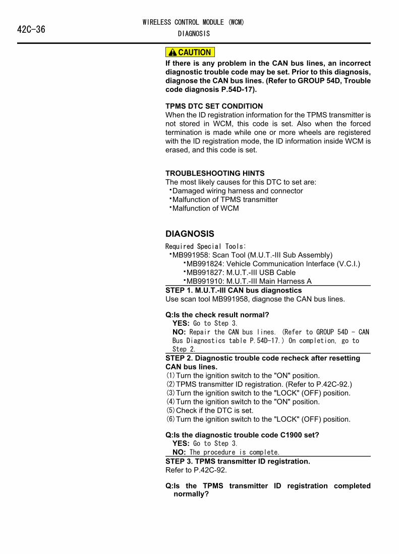
If there is any problem in the CAN bus lines, an incorrectdiagnostic trouble code may be set. Prior to this diagnosis,diagnose the CAN bus lines. (Refer to GROUP 54D, Troublecode diagnosis P.54D-17).
TPMS DTC SET CONDITIONWhen the ID registration information for the TPMS transmitter isnot stored in WCM, this code is set. Also when the forcedtermination is made while one or more wheels are registeredwith the ID registration mode, the ID information inside WCM iserased, and this code is set.
TROUBLESHOOTING HINTSThe most likely causes for this DTC to set are:⦆Damaged wiring harness and connector⦆Malfunction of TPMS transmitter⦆Malfunction of WCM
DIAGNOSISRequired Special Tools:⦆MB991958: Scan Tool (M.U.T.-III Sub Assembly)
⦆MB991824: Vehicle Communication Interface (V.C.I.)⦆MB991827: M.U.T.-III USB Cable⦆MB991910: M.U.T.-III Main Harness A
STEP 1. M.U.T.-III CAN bus diagnosticsUse scan tool MB991958, diagnose the CAN bus lines.
Q:Is the check result normal?YES: Go to Step 3.NO: Repair the CAN bus lines. (Refer to GROUP 54D - CANBus Diagnostics table P.54D-17.) On completion, go toStep 2.
STEP 2. Diagnostic trouble code recheck after resettingCAN bus lines.(1)Turn the ignition switch to the "ON" position.(2)TPMS transmitter ID registration. (Refer to P.42C-92.)(3)Turn the ignition switch to the "LOCK" (OFF) position.(4)Turn the ignition switch to the "ON" position.(5)Check if the DTC is set.(6)Turn the ignition switch to the "LOCK" (OFF) position.
Q:Is the diagnostic trouble code C1900 set?YES: Go to Step 3.NO: The procedure is complete.
STEP 3. TPMS transmitter ID registration.Refer to P.42C-92.
Q:Is the TPMS transmitter ID registration completednormally?
42C-36WIRELESS CONTROL MODULE (WCM)
DIAGNOSIS

YES: Go to Step 5.NO: Replace the TPMS transmitter whose ID code cannot beregistered. Then go to Step 4.
STEP 4. TPMS transmitter ID registration.Refer to P.42C-92.
Q:Is the TPMS transmitter ID registration completednormally?YES: Go to Step 5.NO: Replace the WCM and register the ID codes. (referto P.42C-8.) Then go to Step 5.
STEP 5. Recheck for diagnostic trouble code.Check again if the DTC is set.(1)Turn the ignition switch to the "ON" position.(2)TPMS transmitter ID registration. (Refer to P.42C-92.)(3)Turn the ignition switch to the "LOCK" (OFF) position.(4)Turn the ignition switch to the "ON" position.(5)Check if the DTC is set.(6)Turn the ignition switch to the "LOCK" (OFF) position.
Q:Is the diagnostic trouble code C1900 reset?YES: Replace the WCM and register the ID codes. (referto P.42C-8.) Then start over at Step 1.NO: The procedure is complete.
DTC C1901: Vehicle Speed Information AbnormalityM14209200060USA0000010000
If there is any problem in the CAN bus lines, an incorrectdiagnostic trouble code may be set. Prior to this diagnosis,diagnose the CAN bus lines. (Refer to GROUP 54D, Troublecode diagnosis P.54D-17).
TPMS DTC SET CONDITIONWCM receives the wheel speed information from ABS-ECU orASC-ECU via the CAN-bus line. If the WCM receives informationfrom the ABS-ECU or ASC-ECU indicating the wheel is notcurrently rotating and the TPMS transmitter sends informationindicating the wheel is currently rotating, this code is set.
TROUBLESHOOTING HINTSThe most likely causes for this DTC to set are:⦆Damaged wiring harness and connector⦆Malfunction of TPMS transmitter⦆Malfunction of WCM⦆Malfunction of ABS-ECU or ASC-ECU
WIRELESS CONTROL MODULE (WCM)42C-37DIAGNOSIS
DIAGNOSISRequired Special Tools:⦆MB991958: Scan Tool (M.U.T.-III Sub Assembly)
⦆MB991824: Vehicle Communication Interface (V.C.I.)⦆MB991827: M.U.T.-III USB Cable⦆MB991910: M.U.T.-III Main Harness A
STEP 1. M.U.T.-III CAN bus diagnosticsUse scan tool MB991958, diagnose the CAN bus lines.
Q:Is the check result normal?YES: Go to Step 3.NO: Repair the CAN bus lines. (Refer to GROUP 54D - CANBus Diagnostics table P.54D-17.) On completion, go toStep 2.
STEP 2. Diagnostic trouble code recheck after resettingCAN bus lines.(1)Start the engine and drive the vehicle at 5 km/h or more.(2)Turn the ignition switch to the "LOCK" (OFF) position.(3)Turn the ignition switch to the "ON" position.(4)Check if the DTC is set.(5)Turn the ignition switch to the "LOCK" (OFF) position.
Q:Is the diagnostic trouble code C1901 set?YES: Go to Step 3.NO: The procedure is complete.
STEP 3. Check for other diagnostic trouble code.Check if the diagnostic trouble code is set from ABS-ECU orASC-ECU.<Refer to GROUP 35B, diagnostic trouble codechart P.35B-9(vehicles without ASC) or Refer to GROUP 35C,diagnostic trouble code chart P.35C-11(vehicles with ASC)>
Q:Is the check result normal?YES: Check the registered ID by the transmitter ID checkfunction, and then check the acceleration value of eachwheel by the transmitter check function. If the valueexceeding 5 g is displayed, replace the relevant TPMStransmitter and register the ID code. If the valueexceeding 5 g is not displayed for any TPMS transmitter,replace the WCM and register the ID codes. (Refer to P.42C-8.) Then go to Step 4.NO: Carry out the troubleshooting for ABS-ECU or ASC-ECU.<Refer to GROUP 35B, diagnostic trouble code chart P.35B-9(vehicles without ASC) or Refer to GROUP 35C,diagnostic trouble code chart P.35C-11(vehicles with ASC)>. Then go to Step 4.
STEP 4. Recheck for diagnostic trouble code.(1)Start the engine and drive the vehicle at 5 km/h or more.(2)Turn the ignition switch to the "LOCK" (OFF) position.(3)Turn the ignition switch to the "ON" position.(4)Check if the DTC is set.
42C-38WIRELESS CONTROL MODULE (WCM)
DIAGNOSIS
(5)Turn the ignition switch to the "LOCK" (OFF) position.
Q:Is the diagnostic trouble code C1901 set?YES: Start over at Step 1.NO: The procedure is complete.
DTC C1910: Transmitter Low Battery Voltage Abnormality 1DTC C1920: Transmitter Low Battery Voltage Abnormality 2DTC C1930: Transmitter Low Battery Voltage Abnormality 3DTC C1940: Transmitter Low Battery Voltage Abnormality 4
M14209200061USA0000010000
If there is any problem in the CAN bus lines, an incorrectdiagnostic trouble code may be set. Prior to this diagnosis,diagnose the CAN bus lines. (Refer to GROUP 54D, Troublecode diagnosis P.54D-17).
TPMS DTC SET CONDITIONWhen the voltage of the battery incorporated into the TPMStransmitter becomes low, this code is set.
TROUBLESHOOTING HINTSThe most likely causes for this DTC to set are:⦆Low battery that is incorporated into the TPMS transmitter⦆Damaged wiring harness and connector⦆Malfunction of TPMS transmitter
DIAGNOSISRequired Special Tools:⦆MB991958: Scan Tool (M.U.T.-III Sub Assembly)
⦆MB991824: Vehicle Communication Interface (V.C.I.)⦆MB991827: M.U.T.-III USB Cable⦆MB991910: M.U.T.-III Main Harness A
STEP 1. M.U.T.-III CAN bus diagnosticsUse scan tool MB991958, diagnose the CAN bus lines.
Q:Is the check result normal?YES: Check the registered ID by the transmitter ID checkfunction, and detect the wheel to which the DTC is set bythe transmitter check function. Then, replace the TPMStransmitter, and register the ID codes. (refer to P.42C-8.) Then go to Step 3.NO: Repair the CAN bus lines. (Refer to GROUP 54D - CANBus Diagnostics table P.54D-17.) On completion, go toStep 2.
WIRELESS CONTROL MODULE (WCM)42C-39DIAGNOSIS

STEP 2. Diagnostic trouble code recheck after resettingCAN bus lines(1)Turn the ignition switch to the "ON" position.(2)Check if the DTC is set.(3)Turn the ignition switch to the "LOCK" (OFF) position.
Q:Is the diagnostic trouble code C1910, C1920, C1930 orC1940 set?YES: Start over at Step 1.NO: The procedure is complete.
STEP 3. Recheck for diagnostic trouble code.(1)Turn the ignition switch to the "LOCK" (OFF) position.(2)Turn the ignition switch to the "ON" position.(3)Check if the DTC is set.(4)Turn the ignition switch to the "LOCK" (OFF) position.
Q:Is the diagnostic trouble code C1910, C1920, C1930 orC1940 set?YES: Replace the WCM and register the ID codes. (referto P.42C-8.) Then start over at Step 1.NO: The procedure is complete.
DTC C1911: Reception Abnormality 1DTC C1921: Reception Abnormality 2DTC C1931: Reception Abnormality 3DTC C1941: Reception Abnormality 4
M14209200062USA0000010000
If there is any problem in the CAN bus lines, an incorrectdiagnostic trouble code may be set. Prior to this diagnosis,diagnose the CAN bus lines. (Refer to GROUP 54D, Troublecode diagnosis P.54D-17).
TPMS DTC SET CONDITIONWhen WCM cannot receive the signal from the TPMStransmitter normally, this code is set.
TROUBLESHOOTING HINTSThe most likely causes for this DTC to set are:⦆Damaged wiring harness and connector⦆Malfunction of TPMS transmitter⦆Malfunction of WCM
DIAGNOSISRequired Special Tools:⦆MB991958: Scan Tool (M.U.T.-III Sub Assembly)
⦆MB991824: Vehicle Communication Interface (V.C.I.)
42C-40WIRELESS CONTROL MODULE (WCM)
DIAGNOSIS

⦆MB991827: M.U.T.-III USB Cable⦆MB991910: M.U.T.-III Main Harness A
STEP 1. M.U.T.-III CAN bus diagnosticsUse scan tool to diagnose the CAN bus lines.
Q:Is the check result normal?YES: Check the registered ID by the transmitter ID checkfunction, and detect the wheel to which the DTC is set bythe transmitter check function. Then, replace the TPMStransmitter, and register the ID codes. (Refer to P.42C-8.) If the ID code of replaced TPMS transmitter cannotbe registered, replace the WCM and register the ID code.Then go to Step 3.NO: Repair the CAN bus lines. (Refer to GROUP 54D - CANBus Diagnostics table P.54D-17.) On completion, go toStep 2.
STEP 2. Diagnostic trouble code recheck after resettingCAN bus lines(1)Turn the ignition switch to the "ON" position.(2)Check if the DTC is set.(3)Turn the ignition switch to the "LOCK" (OFF) position.
Q:Is the diagnostic trouble code C1911, C1921, C1931 orC1941 set?YES: Start over at Step 1.NO: The procedure is complete.
STEP 3. Recheck for diagnostic trouble code.(1)Turn the ignition switch to the "LOCK" (OFF) position.(2)Turn the ignition switch to the "ON" position.(3)Check if the DTC is set.(4)Turn the ignition switch to the "LOCK" (OFF) position.
Q:Is the diagnostic trouble code C1911, C1921, C1931 orC1941 set?YES: Replace the WCM and register the ID codes. (referto P.42C-8.) Then start over at Step 1.NO: The procedure is complete.
DTC C1912: Tire Inflation pressure Warning 1DTC C1922: Tire Inflation pressure Warning 2DTC C1932: Tire Inflation pressure Warning 3DTC C1942: Tire Inflation pressure Warning 4
M14209200063USA0000010000
If there is any problem in the CAN bus lines, an incorrectdiagnostic trouble code may be set. Prior to this diagnosis,diagnose the CAN bus lines. (Refer to GROUP 54D, Troublecode diagnosis P.54D-17).
WIRELESS CONTROL MODULE (WCM)42C-41DIAGNOSIS

TPMS DTC SET CONDITIONWhen the tire pressure becomes lower than the specified value,the TPMS transmitter sends the signal to WCM, and then WCMsets this code.
TROUBLESHOOTING HINTSThe most likely causes for this DTC to set is:⦆Drop of the tire pressure⦆Loose TPMS transmitter mounting nut⦆Flat tire⦆TPMS transmitter malfunction⦆WCM malfunction⦆CAN-bus line malfunction
DIAGNOSISRequired Special Tools:⦆MB991958: Scan Tool (M.U.T.-III Sub Assembly)
⦆MB991824: Vehicle Communication Interface (V.C.I.)⦆MB991827: M.U.T.-III USB Cable⦆MB991910: M.U.T.-III Main Harness A
STEP 1. M.U.T.-III CAN bus diagnosticsUse scan tool MB991958, diagnose the CAN bus lines.
Q:Is the check result normal?YES: Go to Step 3.NO: Repair the CAN bus lines. (Refer to GROUP 54D - CANBus Diagnostics table P.54D-17.) On completion, go toStep 2.
STEP 2. Diagnostic trouble code recheck after resettingCAN bus lines
Q:Is DTC C1912, C1922, C1932 or C1942 set?YES: Go to Step 3.NO: The procedure is complete.
STEP 3. Tire pressure checkCheck that the pressure of the tire corresponds to the set DTCis normal.
Q:Is the check result normal?YES: Go to Step 5.NO: Go to Step 4.
STEP 4. Tire checkCheck that there is no abnormality for the items below.⦆Flat tire⦆Cracked tire⦆Air leak from valve⦆Loose TPMS transmitter mounting nut (Refer to P.42C-99.)
Q:Is the check result normal?
42C-42WIRELESS CONTROL MODULE (WCM)
DIAGNOSIS

YES: Go to Step 5.NO: Replace it. Then go to Step 7.
STEP 5. Tire pressure check by M.U.T.-III(1)Check the registered ID code by the transmitter ID check
function.(2)Check the wheel to which the DTC is set by the transmitter
check function.(3)Using the M.U.T.-III, check the relevant tire pressure.(4)Using the tire pressure gauge, check the tire pressure at the
air valve of relevant tire. Then, measure the differencebetween that checked tire pressure and the tire pressuredisplayed at the procedure (3).
OK: 20 kPa or less
Q:Is the check result normal?YES: Go to Step 6.NO: Replace the TPMS transmitter and register the IDcodes. (refer to P.42C-8.) Then go to Step 7.
STEP 6. Tire pressure check by M.U.T.-III(1)Check the registered ID code by the transmitter ID check
function.(2)Check the wheel to which the DTC is set by the transmitter
check function.(3)Using the M.U.T.-III, check the relevant tire pressure.(4)Using the tire pressure gauge, check the tire pressure at the
air valve of relevant tire. Then, measure the differencebetween that checked tire pressure and the tire pressuredisplayed at the procedure (3).
OK: 20 kPa or less
Q:Is the check result normal?YES: Go to Step 7.NO: Replace the WCM and register the ID codes. (referto P.42C-8.) Then go to Step 7.
STEP 7. Recheck for diagnostic trouble code.(1)Correct the tire pressure for all wheels.(2)Turn the ignition switch to the "LOCK" (OFF) position.(3)Turn the ignition switch to the "ON" position.(4)Check if the DTC is set.(5)Turn the ignition switch to the "LOCK" (OFF) position.
Q:Is the diagnostic trouble code C1912, C1922, C1932 orC1942 set?YES: Start over at Step 1.NO: The procedure is complete.
DTC C1913: Acceleration Sensor Abnormality 1DTC C1923: Acceleration Sensor Abnormality 2DTC C1933: Acceleration Sensor Abnormality 3
WIRELESS CONTROL MODULE (WCM)42C-43DIAGNOSIS
DTC C1943: Acceleration Sensor Abnormality 4M14209200064USA0000010000
If there is any problem in the CAN bus lines, an incorrectdiagnostic trouble code may be set. Prior to this diagnosis,diagnose the CAN bus lines. (Refer to GROUP 54D, Troublecode diagnosis P.54D-17).
TPMS DTC SET CONDITIONThe TPMS transmitter detects if the wheel is rotated and sendsthe signals to WCM. When the TPMS transmitter judges that theportion for detecting the wheel rotation is failed, the failure signalis sent to WCM, and WCM sets this code.
TROUBLESHOOTING HINTSThe most likely causes for this DTC to set are:⦆Damaged wiring harness and connector⦆Malfunction of TPMS transmitter⦆Malfunction of WCM
DIAGNOSISRequired Special Tools:⦆MB991958: Scan Tool (M.U.T.-III Sub Assembly)
⦆MB991824: Vehicle Communication Interface (V.C.I.)⦆MB991827: M.U.T.-III USB Cable⦆MB991910: M.U.T.-III Main Harness A
STEP 1. M.U.T.-III CAN bus diagnosticsUse scan tool MB991958, diagnose the CAN bus lines.
Q:Is the check result normal?YES: Check the registered ID by the transmitter ID checkfunction, and detect the wheel to which the DTC is set bythe transmitter check function. Then, replace the TPMStransmitter, and register the ID codes. (Refer to P.42C-8.) Then go to Step 3.NO: Repair the CAN bus lines. (Refer to GROUP 54D - CANBus Diagnostics table P.54D-17.) On completion, go toStep 2.
STEP 2. Diagnostic trouble code recheck after resettingCAN bus lines.(1)Turn the ignition switch to the "ON" position.(2)Check if the DTC is set.(3)Turn the ignition switch to the "LOCK" (OFF) position.
Q:Is the diagnostic trouble code C1913, C1923, C1933 orC1943 set?YES: Start over at Step 1.NO: The procedure is complete.
42C-44WIRELESS CONTROL MODULE (WCM)
DIAGNOSIS
STEP 3. Recheck for diagnostic trouble code.(1)Turn the ignition switch to the "LOCK" (OFF) position.(2)Turn the ignition switch to the "ON" position.(3)Check if the DTC is set.(4)Turn the ignition switch to the "LOCK" (OFF) position.
Q:Is the diagnostic trouble code C1913, C1923, C1933 orC1943 set?YES: Replace the WCM and register the ID codes. (referto P.42C-8.) Then start over at Step 1.NO: The procedure is complete.
DTC C1914: Pressure Sensor Abnormality 1DTC C1924: Pressure Sensor Abnormality 2DTC C1934: Pressure Sensor Abnormality 3DTC C1944: Pressure Sensor Abnormality 4
M14209200065USA0000010000
If there is any problem in the CAN bus lines, an incorrectdiagnostic trouble code may be set. Prior to this diagnosis,diagnose the CAN bus lines. (Refer to GROUP 54D, Troublecode diagnosis P.54D-17).
TPMS DTC SET CONDITIONThe TPMS transmitter detects if the tire pressure is normal andsends the signal to WCM. When the TPMS transmitter judgesthat the portion for detecting the tire pressure is failed, the failuresignal is sent to WCM, and WCM sets this code.
TROUBLESHOOTING HINTSThe most likely causes for this DTC to set are:⦆Damaged wiring harness and connector⦆Malfunction of TPMS transmitter⦆Malfunction of WCM
DIAGNOSISRequired Special Tools:⦆MB991958: Scan Tool (M.U.T.-III Sub Assembly)
⦆MB991824: Vehicle Communication Interface (V.C.I.)⦆MB991827: M.U.T.-III USB Cable⦆MB991910: M.U.T.-III Main Harness A
STEP 1. M.U.T.-III CAN bus diagnosticsUse scan tool MB991958, diagnose the CAN bus lines.
Q:Is the check result normal?YES: Check the registered ID by the transmitter ID checkfunction, and detect the wheel to which the DTC is set by
WIRELESS CONTROL MODULE (WCM)42C-45DIAGNOSIS

the transmitter check function. Then, replace the TPMStransmitter, and register the ID codes. (Refer to P.42C-8.) Then go to Step 3.NO: Repair the CAN bus lines. (Refer to GROUP 54D - CANBus Diagnostics table P.54D-17.) On completion, go toStep 2.
STEP 2. Diagnostic trouble code recheck after resettingCAN bus lines.(1)Turn the ignition switch to the "ON" position.(2)Check if the DTC is set.(3)Turn the ignition switch to the "LOCK" (OFF) position.
Q:Is the diagnostic trouble code C1914, C1924, C1934 orC1944 set?YES: Start over at Step 1.NO: The procedure is complete.
STEP 3. Recheck for diagnostic trouble code.(1)Turn the ignition switch to the "LOCK" (OFF) position.(2)Turn the ignition switch to the "ON" position.(3)Check if the DTC is set.(4)Turn the ignition switch to the "LOCK" (OFF) position.
Q:Is the diagnostic trouble code C1914, C1924, C1934 orC1944 set?YES: Replace the WCM and register the ID codes. (referto P.42C-8.) Then start over at Step 1.NO: The procedure is complete.
DTC U0019: Bus off(CAN-B)M14209200024USA0000010000
⦆If DTC U0019 is set, be sure to diagnose the CANbus line.
⦆When replacing the ECU, always check that thecommunication circuit is normal.
DTC SET CONDITIONIf the CAN-B circuit malfunctions, the WCM sets DTCU0019.
TECHNICAL DESCRIPTION(COMMENT)If WCM cannot perform the data transmission innormal conditions due to a malfunction of the CAN-Bbus circuit, WCM determines that there is a problem.
TROUBLESHOOTING HINTThe CAN bus line may be defective
DIAGNOSISRequired Special Tools:⦆MB991958: Scan Tool (M.U.T.-III Sub Assembly)
⦆MB991824: Vehicle Communication Interface (V.C.I.)⦆MB991827: M.U.T.-III USB Cable⦆MB991910: M.U.T.-III Main Harness A (Vehicles with
CAN communication system)STEP 1.Recheck for diagnostic trouble code.Check again if the DTC is set to the WCM.
42C-46WIRELESS CONTROL MODULE (WCM)
DIAGNOSIS

ZC501967AC404789
ZC5019680000
MB991824
MB991827
MB991910
Data linkconnector To prevent damage to scan tool MB991958, always turn the
ignition switch to the "LOCK" (OFF) position beforeconnecting or disconnecting scan tool MB991958.(1)Connect scan tool MB991958. Refer to "How to connect the
Scan Tool (M.U.T.-III) P.42C-7."(2)Turn the ignition switch from "LOCK" (OFF) position to "ON"
position.(3)Check if DTC is set.(4)Turn the ignition switch to the "LOCK" (OFF) position.
Q:Is the DTC set?YES: Go to Step 2.NO: The trouble can be an intermittent malfunction (Referto GROUP 00 - How to use Troubleshooting/inspectionService Points - How to Cope with IntermittentMalfunction P.00-15).
STEP 2. Using scan tool MB991958, diagnose the CAN busline.(1)Turn the ignition switch to the "ON" position.(2)Diagnose the CAN bus line.(3)Turn the ignition switch to the "LOCK" (OFF) position.
Q:Is the CAN bus line found to be normal?YES: The trouble can be an intermittent malfunction(Refer to GROUP 00 - How to use Troubleshooting/inspection Service Points - How to Cope with IntermittentMalfunction P.00-15).NO: Repair the CAN bus line. (Refer to GROUP 54D,Diagnosis P.54D-17).
DTC U0141: ETACS-ECU CAN timeoutM14209200025USA0000010000
⦆If the DTC U0141 is set, be sure to diagnose theCAN bus line.
⦆When replacing the ECU, always check that thecommunication circuit is normal.
DIAGNOSTIC FUNCTIONIf the signal from ETACS-ECU cannot be received,the WCM sets DTC U0141.
TROUBLESHOOTING HINTS⦆Malfunction of CAN bus line⦆Malfunction of WCM⦆Malfunction of ETACS-ECU
DIAGNOSISRequired Special Tools:⦆MB991958: Scan Tool (M.U.T.-III Sub Assembly)
WIRELESS CONTROL MODULE (WCM)42C-47DIAGNOSIS

⦆MB991824: Vehicle Communication Interface (V.C.I.)⦆MB991827: M.U.T.-III USB Cable⦆MB991910: M.U.T.-III Main Harness A (Vehicles with
CAN communication system)STEP 1. Using scan tool MB991958, diagnose the CAN busline.
ZC501967AC404789
ZC5019680000
MB991824
MB991827
MB991910
Data linkconnector To prevent damage to scan tool MB991958, always turn the
ignition switch to the "LOCK" (OFF) position beforeconnecting or disconnecting scan tool MB991958.(1)Connect scan tool MB991958. Refer to "How to connect the
Scan Tool (M.U.T.-III) P.42C-7."(2)Turn the ignition switch to the "ON" position.(3)Diagnose the CAN bus line.(4)Turn the ignition switch to the "LOCK" (OFF) position.
Q:Is the CAN bus line found to be normal?YES: Go to Step 2.NO: Repair the CAN bus line. (Refer to GROUP 54D,Diagnosis P.54D-17).
STEP 2. Using scan tool MB991958, read the ETACS-ECUdiagnostic trouble code.Check again if the DTC is set to the ETACS-ECU.
Q:Is the DTC set?YES: Diagnose the ETACS-ECU (Refer to GROUP 54Ad - P.54Ad-8).NO: Go to Step 3.
STEP 3. Recheck for diagnostic trouble code.Check again if the DTC is set to the WCM.(1)Erase the DTC.(2)Turn the ignition switch from "LOCK" (OFF) position to "ON"
position.(3)Check if DTC is set.(4)Turn the ignition switch to the "LOCK" (OFF) position.
Q:Is the DTC set?YES: Replace WCM and register the ID codes. (Refer to P.42C-8.)NO: The trouble can be an intermittent malfunction (Referto GROUP 00 - How to use Troubleshooting/inspectionService Points - How to Cope with IntermittentMalfunction P.00-15).
42C-48WIRELESS CONTROL MODULE (WCM)
DIAGNOSIS

DTC U0151: SRS-ECU CAN timeoutM14209200026USA0000010000
⦆If the DTC U0151 is set, be sure to diagnose theCAN bus line.
⦆When replacing the ECU, always check that thecommunication circuit is normal.
DIAGNOSTIC FUNCTIONIf no signal from SRS-ECU can be received, WCMsets diagnostic trouble code U0151.
TROUBLESHOOTING HINTS⦆The CAN bus line may be defective⦆The SRS-ECU may be defective⦆Malfunction of WCM
DIAGNOSISRequired Special Tools:⦆MB991958: Scan Tool (M.U.T.-III Sub Assembly)
⦆MB991824: Vehicle Communication Interface (V.C.I.)⦆MB991827: M.U.T.-III USB Cable⦆MB991910: M.U.T.-III Main Harness A (Vehicles with
CAN communication system)STEP 1. Using scan tool MB991958, diagnose the CAN busline.
ZC501967AC404789
ZC5019680000
MB991824
MB991827
MB991910
Data linkconnector To prevent damage to scan tool MB991958, always turn the
ignition switch to the "LOCK" (OFF) position beforeconnecting or disconnecting scan tool MB991958.(1)Connect scan tool MB991958. Refer to "How to connect the
Scan Tool (M.U.T.-III) P.42C-7."(2)Turn the ignition switch to the "ON" position.(3)Diagnose the CAN bus line.(4)Turn the ignition switch to the "LOCK" (OFF) position.
Q:Is the CAN bus line found to be normal?YES: Go to Step 2.NO: Repair the CAN bus line. (Refer to GROUP 54D,Diagnosis P.54D-17).
STEP 2. Using scan tool MB991958, read the SRS-ECUdiagnostic trouble code.Check again if the DTC is set to the SRS-ECU.
Q:Is the DTC set?YES: Troubleshoot the SRS (Refer to GROUP 52B,Troubleshooting P.52B-33).
WIRELESS CONTROL MODULE (WCM)42C-49DIAGNOSIS
NO: Go to Step 3.STEP 3. Recheck for diagnostic trouble code.Check again if the DTC is set to the WCM.(1)Erase the DTC.(2)Turn the ignition switch from "LOCK" (OFF) position to "ON"
position.(3)Check if DTC is set.(4)Turn the ignition switch to the "LOCK" (OFF) position.
Q:Is the DTC set?YES: Replace WCM and register the ID codes. (Refer to P.42C-8.)NO: The trouble can be an intermittent malfunction (Referto GROUP 00 - How to use Troubleshooting/inspectionService Points - How to Cope with IntermittentMalfunction P.00-15).
DTC U0154: Occupant classification-ECU CAN timeoutM14209200073USA0000010000
⦆If DTC U0154 is set, be sure to diagnose the CANbus line.
⦆When replacing the ECU, always check that thecommunication circuit is normal.
DIAGNOSTIC FUNCTIONWhen the signals from occupant classification-ECUcannot be received, the WCM sets DTC U0154.
TROUBLESHOOTING HINTS⦆The CAN bus line may be defective.⦆The WCM may be defective.⦆The occupant classification-ECU may be defective.
DIAGNOSISRequired Special Tools:⦆MB991958: Scan Tool (M.U.T.-III Sub Assembly)
⦆MB991824: Vehicle Communication Interface (V.C.I.)⦆MB991827: M.U.T.-III USB Cable⦆MB991910: M.U.T.-III Main Harness A (Vehicles with
CAN communication system)
42C-50WIRELESS CONTROL MODULE (WCM)
DIAGNOSIS
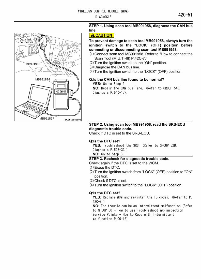
STEP 1. Using scan tool MB991958, diagnose the CAN busline.
ZC501967AC404789
ZC5019680000
MB991824
MB991827
MB991910
Data linkconnector To prevent damage to scan tool MB991958, always turn the
ignition switch to the "LOCK" (OFF) position beforeconnecting or disconnecting scan tool MB991958.(1)Connect scan tool MB991958. Refer to "How to connect the
Scan Tool (M.U.T.-III) P.42C-7."(2)Turn the ignition switch to the "ON" position.(3)Diagnose the CAN bus line.(4)Turn the ignition switch to the "LOCK" (OFF) position.
Q:Is the CAN bus line found to be normal?YES: Go to Step 2.NO: Repair the CAN bus line. (Refer to GROUP 54D,Diagnosis P.54D-17).
STEP 2. Using scan tool MB991958, read the SRS-ECUdiagnostic trouble code.Check if DTC is set to the SRS-ECU.
Q:Is the DTC set?YES: Troubleshoot the SRS. (Refer to GROUP 52B,Diagnosis P.52B-33.)NO: Go to Step 3.
STEP 3. Recheck for diagnostic trouble code.Check again if the DTC is set to the WCM.(1)Erase the DTC.(2)Turn the ignition switch from "LOCK" (OFF) position to "ON"
position.(3)Check if DTC is set.(4)Turn the ignition switch to the "LOCK" (OFF) position.
Q:Is the DTC set?YES: Replace WCM and register the ID codes. (Refer to P.42C-8.)NO: The trouble can be an intermittent malfunction (Referto GROUP 00 - How to use Troubleshooting/inspectionService Points - How to Cope with IntermittentMalfunction P.00-15).
WIRELESS CONTROL MODULE (WCM)42C-51DIAGNOSIS

DTC U0155: Combination meter CAN timeoutM14209200027USA0000010000
⦆If the diagnostic trouble code U0155 is set, besure to diagnose the CAN bus line.
⦆When replacing the ECU, always check that thecommunication circuit is normal.
TROUBLE JUDGMENTIf no signal from the combination meter can bereceived, WCM sets DTC U0155.
TROUBLESHOOTING HINTS⦆Malfunction of CAN bus line⦆Combination meter malfunction⦆Malfunction of WCM
DIAGNOSISRequired Special Tools:⦆MB991958: Scan Tool (M.U.T.-III Sub Assembly)
⦆MB991824: Vehicle Communication Interface (V.C.I.)⦆MB991827: M.U.T.-III USB Cable⦆MB991910: M.U.T.-III Main Harness A (Vehicles with
CAN communication system)STEP 1. Using scan tool MB991958, diagnose the CAN busline.
ZC501967AC404789
ZC5019680000
MB991824
MB991827
MB991910
Data linkconnector To prevent damage to scan tool MB991958, always turn the
ignition switch to the "LOCK" (OFF) position beforeconnecting or disconnecting scan tool MB991958.(1)Connect scan tool MB991958. Refer to "How to connect the
Scan Tool (M.U.T.-III) P.42C-7."(2)Turn the ignition switch to the "ON" position.(3)Diagnose the CAN bus line.(4)Turn the ignition switch to the "LOCK" (OFF) position.
Q:Is the CAN bus line found to be normal?YES: Go to Step 2.NO: Repair the CAN bus line. (Refer to GROUP 54D,Diagnosis P.54D-17).
STEP 2. Using scan tool MB991958, read the combinationmeter diagnostic trouble code.Check if DTC is set to the combination meter.
Q:Is the DTC set?YES: Troubleshoot the combination meter. (Refer to GROUP54Ab, Diagnosis P.54Ab-7.)
42C-52WIRELESS CONTROL MODULE (WCM)
DIAGNOSIS
NO: Go to Step 3.STEP 3. Using scan tool MB991958, read the A/C-ECUdiagnostic trouble code.Check if the DTC U0155 is set to the A/C-ECU.
Q:Is the DTC set?YES: Go to Step 4.NO: Go to Step 5.
STEP 4. Recheck for diagnostic trouble code.Check again if the DTC is set to the WCM.(1)Erase the DTC.(2)Turn the ignition switch from "LOCK" (OFF) position to "ON"
position.(3)Check if DTC is set.(4)Turn the ignition switch to the "LOCK" (OFF) position.
Q:Is the DTC set?YES: Replace the combination meter.NO: The trouble can be an intermittent malfunction suchas a poor connection or open circuit in the CAN bus linesbetween the combination meter and the WCM. (Refer to GROUP00, How to Cope with Intermittent Malfunction P.00-15)
STEP 5. Recheck for diagnostic trouble code.Check again if the DTC is set to the WCM.(1)Erase the DTC.(2)Turn the ignition switch from "LOCK" (OFF) position to "ON"
position.(3)Check if DTC is set.(4)Turn the ignition switch to the "LOCK" (OFF) position.
Q:Is the DTC set?YES: Replace WCM and register the ID codes. (Refer to P.42C-8.)NO: The trouble can be an intermittent malfunction suchas a poor connection or open circuit in the CAN bus linesbetween the combination meter and the WCM. (Refer to GROUP00, How to Cope with Intermittent Malfunction P.00-15)
DTC U0164: A/C-ECU CAN timeoutM14209200028USA0000010000
⦆If DTC U0164 is set, be sure to diagnose the CANbus line.
⦆When replacing the ECU, always check that thecommunication circuit is normal.
DIAGNOSTIC FUNCTIONIf the signal from A/C-ECU cannot be received, theWCM sets DTC U0164.
TROUBLESHOOTING HINTS⦆The CAN bus line may be defective.⦆The A/C-ECU may be defective.⦆The WCM may be defective.
WIRELESS CONTROL MODULE (WCM)42C-53DIAGNOSIS

DIAGNOSISRequired Special Tools:⦆MB991958: Scan Tool (M.U.T.-III Sub Assembly)
⦆MB991824: Vehicle Communication Interface (V.C.I.)⦆MB991827: M.U.T.-III USB Cable⦆MB991910: M.U.T.-III Main Harness A (Vehicles with
CAN communication system)STEP 1. Using scan tool MB991958, diagnose the CAN busline
ZC501967AC404789
ZC5019680000
MB991824
MB991827
MB991910
Data linkconnector To prevent damage to scan tool MB991958, always turn the
ignition switch to the "LOCK" (OFF) position beforeconnecting or disconnecting scan tool MB991958.(1)Connect scan tool MB991958. Refer to "How to connect the
Scan Tool (M.U.T.-III) P.42C-7."(2)Turn the ignition switch to the "ON" position.(3)Diagnose the CAN bus line.(4)Turn the ignition switch to the "LOCK" (OFF) position.
Q:Is the CAN bus line found to be normal?YES: Go to Step 2.NO: Repair the CAN bus line. (Refer to GROUP 54D,Diagnosis P.54D-17).
STEP 2. Using scan tool MB991958, read the A/C diagnostictrouble codeCheck if DTC is set to the A/C-ECU.
Q:Is the DTC set?YES: Troubleshoot the A/C (Refer to GROUP 55A, Manual A/C Diagnosis P.55A-8or GROUP 55B, Auto A/C Diagnosis P.55B-7).NO: Go to Step 3.
STEP 3. Recheck for diagnostic trouble code.Check again if the DTC is set to the WCM.(1)Erase the DTC.(2)Turn the ignition switch from "LOCK" (OFF) position to "ON"
position.(3)Check if DTC is set.(4)Turn the ignition switch to the "LOCK" (OFF) position.
Q:Is the DTC set?YES: Replace WCM and register the ID codes. (Refer to P.42C-8.)
42C-54WIRELESS CONTROL MODULE (WCM)
DIAGNOSIS

NO: The trouble can be an intermittent malfunction (Referto GROUP 00 - How to use Troubleshooting/inspectionService Points - How to Cope with IntermittentMalfunction P.00-15).
DTC U0184: Audio CAN timeoutM14209200029USA0000010000
⦆If DTC U0184 is set, be sure to diagnose the CANbus line.
⦆When replacing the ECU, always check that thecommunication circuit is normal.
DIAGNOSTIC FUNCTIONWhen the signals from radio and CD player or CDchanger cannot be received, the WCM sets DTCU0184.
TROUBLESHOOTING HINTS⦆The CAN bus line may be defective.⦆The WCM may be defective.⦆The radio and CD player or CD changer may be
defective.
DIAGNOSISRequired Special Tools:⦆MB991958: Scan Tool (M.U.T.-III Sub Assembly)
⦆MB991824: Vehicle Communication Interface (V.C.I.)⦆MB991827: M.U.T.-III USB Cable⦆MB991910: M.U.T.-III Main Harness A (Vehicles with
CAN communication system)STEP 1. Using scan tool MB991958, diagnose the CAN busline.
ZC501967AC404789
ZC5019680000
MB991824
MB991827
MB991910
Data linkconnector To prevent damage to scan tool MB991958, always turn the
ignition switch to the "LOCK" (OFF) position beforeconnecting or disconnecting scan tool MB991958.(1)Connect scan tool MB991958. Refer to "How to connect the
Scan Tool (M.U.T.-III) P.42C-7."(2)Turn the ignition switch to the "ON" position.(3)Diagnose the CAN bus line.(4)Turn the ignition switch to the "LOCK" (OFF) position.
Q:Is the CAN bus line found to be normal?YES: Go to Step 2.NO: Repair the CAN bus line. (Refer to GROUP 54D,Diagnosis P.54D-17).
WIRELESS CONTROL MODULE (WCM)42C-55DIAGNOSIS

STEP 2. Using scan tool MB991958, read the audiodiagnostic trouble code.Check again if the DTC is set to the audio.
Q:Is the DTC set?YES: Troubleshoot the radio and CD player. Refer to GROUP54B, Diagnosis <radio and CD player> P.54B-7.NO: Go to Step 3.
STEP 3. Recheck for diagnostic trouble code.Check again if the DTC is set to the WCM.(1)Erase the DTC.(2)Turn the ignition switch from "LOCK" (OFF) position to "ON"
position.(3)Check if DTC is set.(4)Turn the ignition switch to the "LOCK" (OFF) position.
Q:Is the DTC set?YES: Replace WCM and register the ID codes. (Refer to P.42C-8.)NO: The trouble can be an intermittent malfunction (Referto GROUP 00 - How to use Troubleshooting/inspectionService Points - How to Cope with IntermittentMalfunction P.00-15).
DTC U0195: Satellite radio tuner CAN timeoutM14209200074USA0000010000
⦆If DTC U0195 is set to the ETACS-ECU, alwaysdiagnose the CAN bus line.
⦆Before replacing the ECU, ensure that thecommunication circuit is normal.
TROUBLE JUDGMENTIf the signal from satellite radio tuner cannot bereceived, the WCM sets DTC U0195.
TROUBLESHOOTING HINTS⦆The satellite radio tuner may be defective.⦆The WCM may be defective.⦆The CAN bus may be defective.
DIAGNOSISRequired Special Tools:⦆MB991958: Scan Tool (M.U.T.-III Sub Assembly)
⦆MB991824: Vehicle Communication Interface (V.C.I.)⦆MB991827: M.U.T.-III USB Cable⦆MB991910: M.U.T.-III Main Harness A (Vehicles with
CAN communication system)
42C-56WIRELESS CONTROL MODULE (WCM)
DIAGNOSIS

STEP 1. Using scan tool MB991958, diagnose the CAN busline.
ZC501967AC404789
ZC5019680000
MB991824
MB991827
MB991910
Data linkconnector To prevent damage to scan tool MB991958, always turn the
ignition switch to the "LOCK" (OFF) position beforeconnecting or disconnecting scan tool MB991958.(1)Connect scan tool MB991958. Refer to "How to connect the
Scan Tool (M.U.T.-III) P.42C-7."(2)Turn the ignition switch to the "ON" position.(3)Diagnose the CAN bus line.(4)Turn the ignition switch to the "LOCK" (OFF) position.
Q:Is the CAN bus line found to be normal?YES: Go to Step 2.NO: Repair the CAN bus line. (Refer to GROUP 54D,Diagnosis P.54D-17).
STEP 2. Using scan tool MB991958, read the satellite radiotuner diagnostic trouble code.Check if DTC is set to the satellite radio tuner.
Q:Is the DTC set?YES: Troubleshoot the satellite radio. (Refer to GROUP54B, Diagnosis <Satellite radio tuner>.)NO: Go to Step 3.
STEP 3. Recheck for diagnostic trouble code.Check again if the DTC is set to the WCM.(1)Erase the DTC.(2)Turn the ignition switch from "LOCK" (OFF) position to "ON"
position.(3)Check if DTC is set.(4)Turn the ignition switch to the "LOCK" (OFF) position.
Q:Is the DTC set?YES: Replace the satellite radio tuner, then go to Step4.NO: The trouble can be an intermittent malfunction suchas a poor connection or open circuit in the CAN bus linesbetween the satellite radio tuner and the WCM. (Refer toGROUP 00, How to Cope with Intermittent Malfunction P.00-15)
STEP 4. Recheck for diagnostic trouble code.Check again if the DTC is set to the WCM.(1)Erase the DTC.(2)Turn the ignition switch from "LOCK" (OFF) position to "ON"
position.(3)Check if DTC is set.
WIRELESS CONTROL MODULE (WCM)42C-57DIAGNOSIS

(4)Turn the ignition switch to the "LOCK" (OFF) position.
Q:Is the DTC set?YES: Replace WCM and register the ID codes. (Refer to P.42C-8.)NO: The trouble can be an intermittent malfunction suchas a poor connection or open circuit in the CAN bus linesbetween the satellite radio tuner and the WCM. (Refer toGROUP 00, How to Cope with Intermittent Malfunction P.00-15)
DTC U0197: Hands free module CAN timeoutM14209200075USA0000010000
⦆If DTC U0197 is set, be sure to diagnose the CANbus line.
⦆When replacing the ECU, always check that thecommunication circuit is normal.
DIAGNOSTIC FUNCTIONWhen the signals from hands free module cannot bereceived, the WCM sets DTC U0197.
TROUBLESHOOTING HINTS⦆The CAN bus line may be defective.⦆The WCM may be defective.⦆The hands free module may be defective.
DIAGNOSISRequired Special Tools:⦆MB991958: Scan Tool (M.U.T.-III Sub Assembly)
⦆MB991824: Vehicle Communication Interface (V.C.I.)⦆MB991827: M.U.T.-III USB Cable⦆MB991910: M.U.T.-III Main Harness A (Vehicles with
CAN communication system)
42C-58WIRELESS CONTROL MODULE (WCM)
DIAGNOSIS
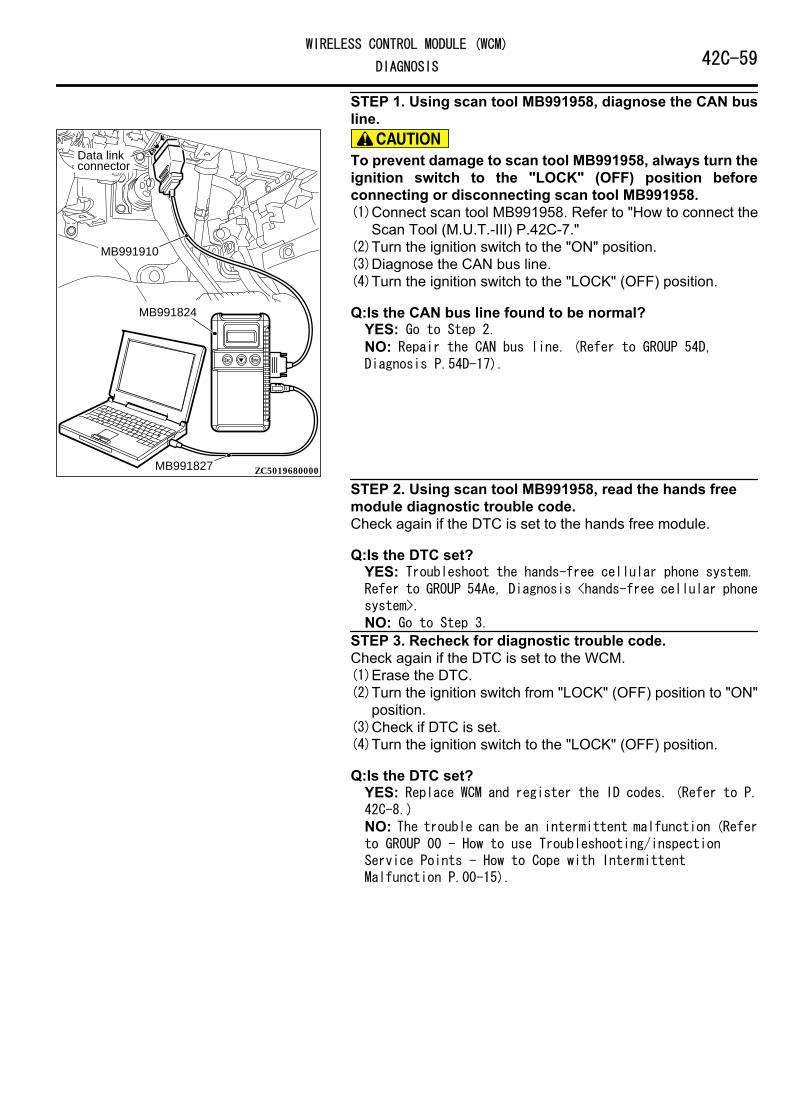
STEP 1. Using scan tool MB991958, diagnose the CAN busline.
ZC501967AC404789
ZC5019680000
MB991824
MB991827
MB991910
Data linkconnector To prevent damage to scan tool MB991958, always turn the
ignition switch to the "LOCK" (OFF) position beforeconnecting or disconnecting scan tool MB991958.(1)Connect scan tool MB991958. Refer to "How to connect the
Scan Tool (M.U.T.-III) P.42C-7."(2)Turn the ignition switch to the "ON" position.(3)Diagnose the CAN bus line.(4)Turn the ignition switch to the "LOCK" (OFF) position.
Q:Is the CAN bus line found to be normal?YES: Go to Step 2.NO: Repair the CAN bus line. (Refer to GROUP 54D,Diagnosis P.54D-17).
STEP 2. Using scan tool MB991958, read the hands freemodule diagnostic trouble code.Check again if the DTC is set to the hands free module.
Q:Is the DTC set?YES: Troubleshoot the hands-free cellular phone system.Refer to GROUP 54Ae, Diagnosis <hands-free cellular phonesystem>.NO: Go to Step 3.
STEP 3. Recheck for diagnostic trouble code.Check again if the DTC is set to the WCM.(1)Erase the DTC.(2)Turn the ignition switch from "LOCK" (OFF) position to "ON"
position.(3)Check if DTC is set.(4)Turn the ignition switch to the "LOCK" (OFF) position.
Q:Is the DTC set?YES: Replace WCM and register the ID codes. (Refer to P.42C-8.)NO: The trouble can be an intermittent malfunction (Referto GROUP 00 - How to use Troubleshooting/inspectionService Points - How to Cope with IntermittentMalfunction P.00-15).
WIRELESS CONTROL MODULE (WCM)42C-59DIAGNOSIS

DTC U0245: Audio visual navigation unit CAN timeoutM14209200076USA0000010000
⦆If DTC U0245 is set, be sure to diagnose the CANbus line.
⦆When replacing the ECU, always check that thecommunication circuit is normal.
DIAGNOSTIC FUNCTIONWhen the signals from audio visual navigation unitcannot be received, the WCM sets DTC U0245.
TROUBLESHOOTING HINTS⦆The CAN bus line may be defective.⦆The WCM may be defective.⦆The audio visual navigation unit may be defective.
DIAGNOSISRequired Special Tools:⦆MB991958: Scan Tool (M.U.T.-III Sub Assembly)
⦆MB991824: Vehicle Communication Interface (V.C.I.)⦆MB991827: M.U.T.-III USB Cable⦆MB991910: M.U.T.-III Main Harness A (Vehicles with
CAN communication system)STEP 1. Using scan tool MB991958, diagnose the CAN busline
ZC501967AC404789
ZC5019680000
MB991824
MB991827
MB991910
Data linkconnector To prevent damage to scan tool MB991958, always turn the
ignition switch to the "LOCK" (OFF) position beforeconnecting or disconnecting scan tool MB991958.(1)Connect scan tool MB991958. Refer to "How to connect the
Scan Tool (M.U.T.-III) P.54Ab-5."(2)Turn the ignition switch to the "ON" position.(3)Diagnose the CAN bus line.(4)Turn the ignition switch to the "LOCK" (OFF) position.
Q:Is the CAN bus line found to be normal?YES: Go to Step 2.NO: Repair the CAN bus line. (Refer to GROUP 54D,Diagnosis P.54D-17).
STEP 2. Using scan tool MB991958, read the audio visualnavigation unit diagnostic trouble code.Check if DTC is set to the audio visual navigation unit.
Q:Is the DTC set?YES: Troubleshoot the MMCS. (Refer to GROUP 54B,Diagnosis <MMCS> P.54B-63.)
42C-60WIRELESS CONTROL MODULE (WCM)
DIAGNOSIS

NO: Go to Step 3.STEP 3. Recheck for diagnostic trouble code.Check again if the DTC is set to the WCM.(1)Erase the DTC.(2)Turn the ignition switch from "LOCK" (OFF) position to "ON"
position.(3)Check if DTC is set.(4)Turn the ignition switch to the "LOCK" (OFF) position.
Q:Is the DTC set?YES: Replace WCM and register the ID codes. (Refer to P.42C-8.)NO: The trouble can be an intermittent malfunction (Referto GROUP 00 - How to use Troubleshooting/inspectionService Points - How to Cope with IntermittentMalfunction P.00-3).
DTC U1412: Implausible Vehicle Speed Signal ReceivedM14209200067USA0000010000
If there is any problem in the CAN bus lines, an incorrectdiagnostic trouble code may be set. Prior to this diagnosis,diagnose the CAN bus lines. (Refer to GROUP 54D, Troublecode diagnosis P.54D-17).
TPMS DTC SET CONDITIONWCM receives the wheel speed information from ABS-ECU orASC-ECU via the CAN-bus line. When WCM cannot receive theinformation about wheel speed sensor from ABS-ECU or ASC-ECU, this code is set.
TROUBLESHOOTING HINTSThe most likely causes for this DTC to set are:⦆Damaged wiring harness and connector⦆Malfunction of ABS-ECU or ASC-ECU⦆Malfunction of WCM
DIAGNOSISRequired Special Tools:⦆MB991958: Scan Tool (M.U.T.-III Sub Assembly)
⦆MB991824: Vehicle Communication Interface (V.C.I.)⦆MB991827: M.U.T.-III USB Cable⦆MB991910: M.U.T.-III Main Harness A
STEP 1. M.U.T.-III CAN bus diagnosticsUse scan tool MB991958, diagnose the CAN bus lines.
Q:Is the check result normal?YES: Go to Step 3.
WIRELESS CONTROL MODULE (WCM)42C-61DIAGNOSIS

NO: Repair the CAN bus lines. (Refer to GROUP 54D - CANBus Diagnostics table P.54D-17.) On completion, go toStep 2.
STEP 2. Diagnostic trouble code recheck after resettingCAN bus lines.(1)Turn the ignition switch to the "LOCK" (OFF) position.(2)Turn the ignition switch to the "ON" position.(3)Check if the DTC is set.(4)Turn the ignition switch to the "LOCK" (OFF) position.
Q:Is the diagnostic trouble code U1412 set?YES: Go to Step 3.NO: The procedure is complete.
STEP 3. Check for other diagnostic trouble code.Check if the diagnostic trouble code is set from ABS-ECU orASC-ECU.<Refer to GROUP 35B, diagnostic trouble codechart P.35B-9(vehicles without ASC) or Refer to GROUP 35C,diagnostic trouble code chart P.35C-11(vehicles with ASC)>
Q:Is the check result normal?YES: Replace the WCM. Then go to Step 4.NO: Carry out the troubleshooting for ABS-ECU or ASC-ECU.<Refer to GROUP 35B, diagnostic trouble code chart P.35B-9(vehicles without ASC) or Refer to GROUP 35C,diagnostic trouble code chart P.35C-11(vehicles with ASC)>. Then go to Step 4.
STEP 4. Recheck for diagnostic trouble code.Check again if the DTC is set.(1)Turn the ignition switch to the "LOCK" (OFF) position.(2)Turn the ignition switch to the "ON" position.(3)Check if the DTC is set.(4)Turn the ignition switch to the "LOCK" (OFF) position.
Q:Is the diagnostic trouble code U1412 reset?YES: Start over at Step 1.NO: The procedure is complete.
DTC U1415: Coding not completed/Data failM14209200030USA0000010000
⦆If DTC U1415 is set, diagnose the CAN bus lines.⦆When replacing the ECU, always check that the
communication circuit is normal.
DIAGNOSTIC FUNCTIONIf the vehicle information data is not registered to thecombination meter, the WCM sets DTC U1415.
JUDGMENT CRITERIAWith the global coding counter value "0," if all theglobal coding data (vehicle information) are notstored, the WCM determines that a problem hasoccurred.
TROUBLESHOOTING HINTS⦆The CAN bus line may be defective.⦆The WCM may be defective.⦆The ETACS-ECU may be defective.
42C-62WIRELESS CONTROL MODULE (WCM)
DIAGNOSIS

DIAGNOSISRequired Special Tools:⦆MB991958: Scan Tool (M.U.T.-III Sub Assembly)
⦆MB991824: Vehicle Communication Interface (V.C.I.)⦆MB991827: M.U.T.-III USB Cable⦆MB991910: M.U.T.-III Main Harness A (Vehicles with
CAN communication system)STEP 1. Using scan tool MB991958, diagnose the CAN busline.
ZC501967AC404789
ZC5019680000
MB991824
MB991827
MB991910
Data linkconnector To prevent damage to scan tool MB991958, always turn the
ignition switch to the "LOCK" (OFF) position beforeconnecting or disconnecting scan tool MB991958.(1)Connect scan tool MB991958. Refer to "How to connect the
Scan Tool (M.U.T.-III) P.42C-7."(2)Turn the ignition switch to the "ON" position.(3)Diagnose the CAN bus line.(4)Turn the ignition switch to the "LOCK" (OFF) position.
Q:Is the CAN bus line found to be normal?YES: Go to Step 2.NO: Repair the CAN bus line. (Refer to GROUP 54D,Diagnosis P.54D-17).
STEP 2. Using scan tool MB991958, read the ETACS-ECUdiagnostic trouble code.Check if DTC is set to the ETACS-ECU.
Q:Is the DTC set?YES: Troubleshoot the ETACS-ECU. Refer to P.54Ad-8.NO: Go to Step 3.
STEP 3. Recheck for diagnostic trouble code.Check again if the DTC is set to the WCM.(1)Erase the DTC.(2)Turn the ignition switch from "LOCK" (OFF) position to "ON"
position.(3)Check if DTC is set.(4)Turn the ignition switch to the "LOCK" (OFF) position.
Q:Is the DTC set?YES: Replace WCM and register the ID codes. (Refer to P.42C-8.)NO: The trouble can be an intermittent malfunction (Referto GROUP 00 - How to use Troubleshooting/inspection
WIRELESS CONTROL MODULE (WCM)42C-63DIAGNOSIS

Service Points - How to Cope with IntermittentMalfunction P.00-15).
Code No.U1417 Implausible coding dataM14209200031USA0000010000
⦆If diagnostic trouble code U1417 is set in WCM, alwaysdiagnose the CAN bus lines. If there is any fault in the CANbus lines, an incorrect diagnostic trouble code may beset. In this case, the set diagnostic trouble code is nothighly reliable.
⦆Before replacing the ECU, ensure that the communicationcircuit is normal.
⦆When diagnostic trouble code U1417 is set in WCM, thediagnostic trouble code may also be set in ETACS-ECU.When the diagnostic trouble code is set in ETACS-ECU,carry out the diagnosis of the diagnostic trouble code forETACS-ECU first.
CIRCUIT OPERATIONWCM receives the vehicle information stored in the ETACS-ECUvia CAN bus lines.
DTC SET CONDITIONSWCM communicates with ETACS-ECU via CAN bus lines. Thisdiagnostic trouble code is set when the vehicle informationreceived from the ETACS-ECU is invalid.
PROBABLE CAUSES⦆Malfunction of ETACS-ECU⦆Engine control module malfunction⦆ETACS-ECUs have been interchanged between two vehicles.⦆WCM malfunction⦆External noise interference⦆WCMs have been interchanged between two vehicles.
DIAGNOSISRequired Special Tools:⦆MB991958: Scan Tool (M.U.T.-III Sub Assembly)
⦆MB991824: Vehicle Communication Interface (V.C.I.)⦆MB991827: M.U.T.-III USB Cable⦆MB991910: M.U.T.-III Main Harness A
42C-64WIRELESS CONTROL MODULE (WCM)
DIAGNOSIS

STEP 1. Using scan tool MB991958, diagnose the CAN busline.
ZC501967AC404789
ZC5019680000
MB991824
MB991827
MB991910
Data linkconnector To prevent damage to scan tool MB991958, always turn the
ignition switch to the "LOCK" (OFF) position beforeconnecting or disconnecting scan tool MB991958.(1)Connect scan tool MB991958. Refer to "How to connect the
Scan Tool (M.U.T.-III) P.42C-7."(2)Turn the ignition switch to the "ON" position.(3)Diagnose the CAN bus line.(4)Turn the ignition switch to the "LOCK" (OFF) position.
Q:Is the CAN bus line found to be normal?YES: Go to Step 2.NO: Repair the CAN bus line. (Refer to GROUP 54D,Diagnosis P.54D-17).
STEP 2. Using scan tool MB991958, read the other systemdiagnostic trouble code.Check if DTC is set to the ETACS-ECU or engine controlmodule.
Q:Is the DTC set?YES (DTC is set to ETACS-ECU.): Troubleshoot the ETACS.(Refer to GROUP 54Ad, Diagnosis P.54Ad-8.)YES (DTC is set to the engine control module.):Troubleshoot the MFI system. (Refer to GROUP 13Ab,Diagnosis P.13Ab-44.)NO: Go to Step 3.
STEP 3. Check part number of ETACS-ECUCheck the part number of ETACS-ECU.
OK: 8637A213
Q:Is the check result normal?YES: Go to Step 4.NO: Replace ETACS-ECU.
STEP 4. Check part number of WCMCheck the part number of WCM.
OK: MN141352
Q:Is the check result normal?YES: Go to Step 5.NO: Replace WCM and register the ID codes. (Refer to P.42C-8.)
STEP 5. Recheck for diagnostic trouble code.Check again if the DTC is set to the WCM.(1)Erase the DTC.
WIRELESS CONTROL MODULE (WCM)42C-65DIAGNOSIS

(2)Turn the ignition switch from "LOCK" (OFF) position to "ON"position.
(3)Check if DTC is set.(4)Turn the ignition switch to the "LOCK" (OFF) position.
Q:Is the DTC set?YES: Replace WCM and register the ID codes. (Refer to P.42C-8.)NO: The trouble can be an intermittent malfunction (Referto GROUP 00 - How to use Troubleshooting/inspectionService Points - How to Cope with IntermittentMalfunction P.00-15).
TROUBLE SYMPTOM CHARTM14209200033USA0000010000
During diagnosis, a DTC associated with othersystem may be set when the ignition switch is
turned on with connector(s) disconnected. Oncompletion, check all systems for diagnostictrouble code(s). If DTC(s) are set, erase them all.
Trouble symptom Inspectionprocedurenumber
Referencepage
Scan tool cannot communicate with WCM. 1 P.42C-66The ignition key cannot be registered using scan tool. 2 P.42C-68Engine does not start. 3 P.42C-69Check the WCM power supply and ground circuits. 4 P.42C-71Keyless entry system does not work. 5 P.42C-73The dome light and the turn-signal lights do not operate through theanswerback function.
6 P.42C-78
The timer lock function does not work after the doors have been unlocked bythe keyless entry system.
7 P.42C-79
SYMPTOM PROCEDURES
Inspection Procedure 1: Scan tool cannot communicate with WCM.M14209200035USA0000010000
Before replacing the ECU, ensure that thecommunication circuit is normal.
TECHNICAL DESCRIPTION (COMMENT)WCM communicates with scan tool via CAN.Therefore, communication error of WCM issuspected.
TROUBLESHOOTING HINTS⦆Malfunction of the power supply or ground of WCM⦆Malfunction of CAN bus line
42C-66WIRELESS CONTROL MODULE (WCM)
DIAGNOSIS

DIAGNOSISRequired Special Tools:⦆MB991958: Scan Tool (M.U.T.-III Sub Assembly)
⦆MB991824: Vehicle Communication Interface (V.C.I.)⦆MB991827: M.U.T.-III USB Cable⦆MB991910: M.U.T.-III Main Harness A (Vehicles with
CAN communication system)STEP 1. Using scan tool MB991958, diagnose the CAN busline.
ZC501967AC404789
ZC5019680000
MB991824
MB991827
MB991910
Data linkconnector To prevent damage to scan tool MB991958, always turn the
ignition switch to the "LOCK" (OFF) position beforeconnecting or disconnecting scan tool MB991958.(1)Connect scan tool MB991958. Refer to "How to connect the
Scan Tool (M.U.T.-III) P.42C-7."(2)Turn the ignition switch to the "ON" position.(3)Diagnose the CAN bus line.(4)Turn the ignition switch to the "LOCK" (OFF) position.
Q:Is the CAN bus line found to be normal?YES: Go to Step 2.NO: Repair the CAN bus line. (Refer to GROUP 54D,Diagnosis P.54D-17).
STEP 2. Check the power supply circuit and the groundcircuit to WCM.Refer to INSPECTION PROCEDURE 4 "Check WCM PowerSupply/Ground Circuits" P.42C-71.
Q:Is the power supply circuit and the ground circuit to WCMin good condition ?YES: Go to Step 3.NO: Repair the power supply circuit and the groundcircuit to WCM.
STEP 3. Retest the systemCheck if scan tool can communicate with WCM.
Q:Does the scan tool cannot communicate with WCM ingood condition?YES: The trouble can be an intermittent malfunction(Refer to GROUP 00 - How to use Troubleshooting/inspection Service Points - How to Cope with IntermittentMalfunction P.00-15).NO: Replace WCM and register the ID codes. (Refer to P.42C-8.)
WIRELESS CONTROL MODULE (WCM)42C-67DIAGNOSIS

Inspection Procedure 2: The ignition key cannot be registered using scan tool.M14209200036USA0000010000
TECHNICAL DESCRIPTION (COMMENT)If only some ignition keys cannot be registered, theignition key itself may be faulty. If no ignition key canbe registered, the key assembly may have alreadybeen registered for another vehicle, or the WCM maybe faulty.
TROUBLESHOOTING HINTS⦆Malfunction of the ignition key⦆Damaged wiring harness and connectors⦆Malfunction of WCM⦆Ignition key registered for other vehicle
DIAGNOSISRequired Special Tools:⦆MB991958: Scan Tool (M.U.T.-III Sub Assembly)
⦆MB991824: Vehicle Communication Interface (V.C.I.)⦆MB991827: M.U.T.-III USB Cable⦆MB991910: M.U.T.-III Main Harness A (Vehicles with
CAN communication system)STEP 1. Check the ignition key inserted in the key cylinderfor interference.
Q:Are there other ignition keys or anything that interfereswith the communication (things that generate radiowaves such as magnets and an air-cleaning device thathas a power plug) near the ignition key inserted in the keycylinder?YES: Move away or remove other ignition keys or thingsthat interfere with the communication (things thatgenerate radio waves such as magnets and a air-cleaningdevice that has a power plug) near the ignition key. Then,go to step 2.NO: Go to Step 3.
STEP 2. Retest the systemCheck that the ignition key can be registered.
Q:Is the ignition key that cannot be registered using scantool in good condition?YES: The procedure is complete.NO: Go to Step 3.
STEP 3. Check which ignition key cannot be registered.
Q:Can any one of the ignition keys be registered?YES (Only some keys): Replace the key that cannot beregistered and register the ID codes. (Refer to P.42C-8.After registering the ID codes, go to Step 5.NO (All keys): Go to Step 4.
STEP 4. Retest the systemCheck the scan tool screen when the key was not able to beregistered.
42C-68WIRELESS CONTROL MODULE (WCM)
DIAGNOSIS
Q:Is the error message of scan tool screen "Abnormality inkey" ?YES (Abnormality in key): Carry out DTC B1A25:Transponder ID unmatched and DTC B1A35: Transponder readerror. Refer to P.42C-20B1A25, P.42C-23B1A35. Then, go toStep 5.NO (ECU internal error): Replace WCM and register the IDcodes. (Refer to P.42C-8. After registering the ID codes,go to Step 5.
STEP 5. Retest the systemCheck that the ignition key can be registered.
Q:Is the ignition key cannot be registered using scan toolin good condition?YES: The procedure is complete.NO: Replace WCM and register the ID codes. (Refer to P.42C-8.)
Inspection Procedure 3: Engine does not start.M14209200037USA0000010000
TECHNICAL DESCRIPTION (COMMENT)If the fuel injection does not work, WCM and the MFIsystem may have a problem. This symptom is notconsidered abnormal when the engine is started by anignition key that has not been registered.
TROUBLESHOOTING HINTS⦆Malfunction of the MFI system
⦆Malfunction of WCM⦆Malfunction of CAN bus line⦆Malfunction of the transponder⦆VIN not programmed
DIAGNOSISRequired Special Tools:⦆MB991958: Scan Tool (M.U.T.-III Sub Assembly)
⦆MB991824: Vehicle Communication Interface (V.C.I.)⦆MB991827: M.U.T.-III USB Cable⦆MB991910: M.U.T.-III Main Harness A (Vehicles with
CAN communication system)STEP 1. Check the battery voltage.Measure the battery voltage when cranking.⦆The voltage should measure 8 volt or more.
Q:Is the measured voltage 8 volt or more?YES: Go to Step 2.NO: Check the battery. (Refer to GROUP 54Aa - Batterytest P.54Aa-3.)
WIRELESS CONTROL MODULE (WCM)42C-69DIAGNOSIS

STEP 2. Using scan tool MB991958, diagnose the CAN busline.
ZC501967AC404789
ZC5019680000
MB991824
MB991827
MB991910
Data linkconnector To prevent damage to scan tool MB991958, always turn the
ignition switch to the "LOCK" (OFF) position beforeconnecting or disconnecting scan tool MB991958.(1)Connect scan tool MB991958. Refer to "How to connect the
Scan Tool (M.U.T.-III) P.42C-7."(2)Turn the ignition switch to the "ON" position.(3)Diagnose the CAN bus line.(4)Turn the ignition switch to the "LOCK" (OFF) position.
Q:Is the CAN bus line found to be normal?YES: Go to Step 3.NO: Repair the CAN bus line. (Refer to GROUP 54D,Diagnosis P.54D-17).
STEP 3. Using scan tool MB991958, read the MFI systemdiagnostic trouble code.Check if DTC is set to the engine control module.
Q:Is the DTC set?YES: Troubleshoot the MFI system. (Refer to GROUP 13Ab,Diagnosis P.13Ab-44.)NO: Go to Step 4.
STEP 4. Using scan tool MB991958, read the WCMdiagnostic trouble code.Check if DTC is set to the WCM.
Q:Is the DTC set?YES: Troubleshoot the WCM. (Refer to P.42C-11.)NO: Go to Step 5.
STEP 5. Check that the engine starts.
Q:Does the engine start?YES: The procedure is complete.NO: Refer to GROUP 13Ab, Diagnosis P.13Ab-44. When thecause of the failure cannot be tracked down by thetroubleshooting in GROUP 13Ab, replace WCM and registerthe ID codes. (Refer to P.42C-8.)
42C-70WIRELESS CONTROL MODULE (WCM)
DIAGNOSIS

Inspection Procedure 4: Check the WCM power supply and ground circuits.M14209200038USA0000010000
WCM Power Supply Circuit
34FUSIBLELINK 36
FUSIBLELINK
IGNITIONSWITCH (IG1)
ETACS-ECU
IGNITION KEYRING ANTENNA ENCRYPTED CODE
TRANSPONDER
IG1RELAY
RELAY BOX
WCM
WIRELESS CONTROL MODULE (WCM)42C-71DIAGNOSIS
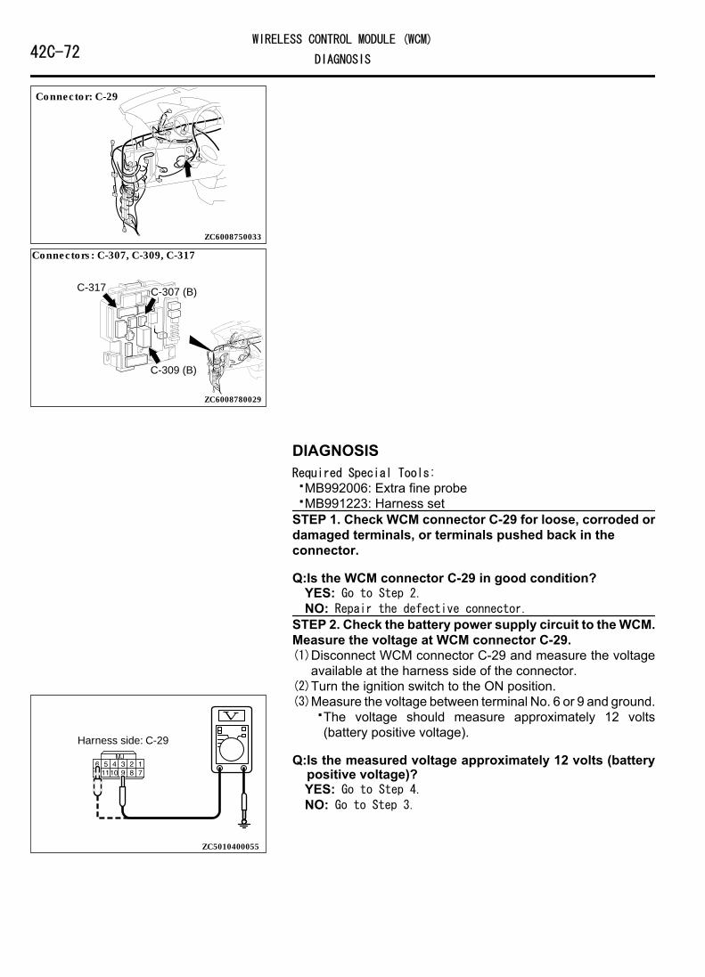
ZC6008750033
Connector: C-29
ZC6008780029
Connectors: C-307, C-309, C-317
C-307 (B)
C-309 (B)
C-317
DIAGNOSISRequired Special Tools:⦆MB992006: Extra fine probe⦆MB991223: Harness setSTEP 1. Check WCM connector C-29 for loose, corroded ordamaged terminals, or terminals pushed back in theconnector.
Q:Is the WCM connector C-29 in good condition?YES: Go to Step 2.NO: Repair the defective connector.
STEP 2. Check the battery power supply circuit to the WCM.Measure the voltage at WCM connector C-29.(1)Disconnect WCM connector C-29 and measure the voltage
available at the harness side of the connector.(2)Turn the ignition switch to the ON position.
ZC5010400055
Harness side: C-29
(3)Measure the voltage between terminal No. 6 or 9 and ground.⦆The voltage should measure approximately 12 volts
(battery positive voltage).
Q:Is the measured voltage approximately 12 volts (batterypositive voltage)?YES: Go to Step 4.NO: Go to Step 3.
42C-72WIRELESS CONTROL MODULE (WCM)
DIAGNOSIS

STEP 3. Check the wiring harness between WCM connectorC-29 (terminal No. 9, 6) and fusible link (36, 34).NOTE: Before checking the wiring harnesses, check theETACS-ECU connectors C-307, C-309, and C-317, and repair ifnecessary.⦆Check the power supply line for open circuit.
Q:Is the wiring harness between WCM connector C-29(terminal No. 9, 6) and fusible link (36, 34) in goodcondition?YES: Go to Step 4.NO: The wiring harness may be damaged or the connector(s) may have loose, corroded or damaged terminals, orterminals pushed back in the connector. Repair the wiringharness as necessary. Verify that the high-beamheadlights illuminate normally.
STEP 4. Check the ground circuit to the WCM. Measure theresistance at WCM connector C-29.(1)Disconnect the connector and measure the resistance at the
wiring harness side.(2)Turn the ignition switch to the ON position.
ZC5010410051
Harness side: C-29
(3)Measure the resistance between terminal No. 7 and theground.⦆The resistance should be 2 Ω or less.
Q:Is the measured resistance 2 Ω or less?YES: The procedure is complete.NO: Go to Step 5.
STEP 5. Check the wiring harness between the WCMconnector C-29 ( terminal No. 7) and the ground.⦆Check the ground wires for open circuit.
Q:Is the wiring harness between WCM connector C-29( terminal No. 7) and the ground in good condition?YES: The procedure is complete.NO: The wiring harness may be damaged or the connector(s) may have loose, corroded or damaged terminals, orterminals pushed back in the connector. Repair the wiringharness as necessary. Verify that the high-beamheadlights illuminate normally.
INSPECTION PROCEDURE 5: Keyless Entry System does not Work.M14209200039USA0000010000
Before replacing the ECU, ensure that the power supplycircuit, the ground circuit and the communication circuit arenormal.
WIRELESS CONTROL MODULE (WCM)42C-73DIAGNOSIS
OPERATIONThe lock/unlock signals from the transmitter are received byWCM, and then sent to ETACS-ECU from WCM. When ETACS-ECU receives signals from the key reminder switch and all thedoor switches, ETACS-ECU actuates the keyless entry system.
PROBABLE CAUSES⦆Malfunction of the key reminder switch⦆Malfunction of the door switches⦆Malfunction of keyless entry transmitter⦆Malfunction of the WCM⦆Malfunction of ETACS-ECU⦆Damaged wiring harness and connectors⦆Option coding information
DIAGNOSTIC PROCEDURERequired Special Tools:⦆MB991223: Harness Set⦆MB992006: Extra Fine Probe⦆MB991958: Scan Tool (M.U.T.-III Sub Assembly)
⦆MB991824: V.C.I.⦆MB991827: M.U.T.-III USB Cable⦆MB991910: M.U.T.-III Main Harness A
STEP 1. Scan tool (M.U.T.-III) CAN bus diagnosticsUse scan tool MB991958 (M.U.T.-III), diagnose the CAN buslines.
Q:Is the CAN bus normal?YES: Go to Step 2.NO: Repair the CAN bus line (Refer to GROUP 54D, CAN busdiagnostics chart P.54D-17).
42C-74WIRELESS CONTROL MODULE (WCM)
DIAGNOSIS

STEP 2. Using scan tool MB991958, read the diagnostictrouble code.
ZC501967AC404789
ZC5019680000
MB991824
MB991827
MB991910
Data linkconnector To prevent damage to scan tool MB991958, always turn the
ignition switch to the "LOCK" (OFF) position beforeconnecting or disconnecting scan tool MB991958.(1)Connect scan tool MB991958. Refer to "How to connect scan
tool (M.U.T.-III) P.42C-7."(2)Turn the ignition switch to the "ON" position.(3)Check whether the ETACS-ECU related DTC is set.(4)Turn the ignition switch to the "LOCK" (OFF) position.
Q:Is the DTC set?YES: Diagnose the ETACS-ECU. Refer to GROUP 54Ad, P.54Ad-8.NO: Go to Step 3.
STEP 3. Check the power supply systemWith the ignition switch in the LOCK (OFF) position, check if thefollowing function operates normally:⦆Hazard warning light
Q:Is the check result normal?YES: Go to Step 4.NO: Refer to GROUP 54Ad, Malfunction of ETACS-ECU powersupply circuit P.54Ad-57.
STEP 4. Verify the central door locking system.
Q:Does the central door locking system work normally?YES: Go to Step 5.NO: Refer to GROUP 42Ab, Trouble Symptom Chart P.42Ab-11.
STEP 5. Using scan tool MB991958, check data list.Check the signals related to the keyless entry system operation.
WIRELESS CONTROL MODULE (WCM)42C-75DIAGNOSIS

ZC501967AC404789
ZC5019680000
MB991824
MB991827
MB991910
Data linkconnector To prevent damage to scan tool MB991958, always turn the
ignition switch to the "LOCK" (OFF) position beforeconnecting or disconnecting scan tool MB991958.(1)Connect scan tool MB991958. Refer to "How to connect the
Scan Tool (M.U.T.-III) P.42C-7."(2)Turn the ignition switch to the "ON" position.(3)Check the ETACS data list.
⦆Turn the ignition switch to the LOCK (OFF) position.⦆Close the driver's door.⦆Close the passenger's door.⦆Close the RH-side rear door.⦆Close the LH-side rear door.⦆Close the liftgate.⦆Remove the ignition key from the ignition key cylinder.
Item No. Item name Normalcondition
Item 254 IG voltage Batteryvoltage
Item 256 Dr door ajar switch CloseItem 257 As door ajar switch CloseItem 258 RR door ajar switch CloseItem 259 RL door ajar switch CloseItem 260 Trunk/gate trunk ajar
switchClose
Item 264 Handle lock switch Key in → Keyout
(4)Turn the ignition switch to the "LOCK" (OFF) position.OK: Normal condition is displayed.
Q:Is the check result normal?YES (Normal conditions are displayed for all the items.):Go to Step 6.NO (Normal condition is not displayed for item No.254.): Refer to GROUP 54Ad, Inspection Procedure 2: ETACS-ECU does not receive any signal from the ignition switch(IG1) P.54Ad-62.NO (Normal condition is not displayed for item No.256.): Refer to GROUP 54Ad, Inspection Procedure 5: ETACS-ECU does not receive any signal from the front door switch(LH) P.54Ad-73.NO (Normal condition is not displayed for item No.257.): Refer to GROUP 54Ad, Inspection Procedure 6: ETACS-ECU does not receive any signal from the front door switch(RH) P.54Ad-75.NO (Normal condition is not displayed for item No.258.): Refer to GROUP 54Ad, Inspection Procedure 8: ETACS-ECU does not receive any signal from the rear door switch(RH) P.54Ad-80.
42C-76WIRELESS CONTROL MODULE (WCM)
DIAGNOSIS

NO (Normal condition is not displayed for item No.259.): Refer to GROUP 54Ad, Inspection Procedure 7: ETACS-ECU does not receive any signal from the rear door switch(LH) P.54Ad-77.NO (Normal condition is not displayed for item No.260.): Refer to GROUP 54Ad, Inspection Procedure 9: ETACS-ECU does not receive any signal from the liftgateswitch P.54Ad-82.NO (Normal condition is not displayed for item No.264.): Refer to GROUP 54Ad, Inspection Procedure 3: ETACS-ECU does not receive any signal from the key reminderswitch. P.54Ad-64.
STEP 6. Using scan tool MB991958, check pulse check.Check the signals related to the keyless entry system operation.
ZC501967AC404789
ZC5019680000
MB991824
MB991827
MB991910
Data linkconnector To prevent damage to scan tool MB991958, always turn the
ignition switch to the "LOCK" (OFF) position beforeconnecting or disconnecting scan tool MB991958.(1)Connect scan tool MB991958. Refer to "How to connect the
Scan Tool (M.U.T.-III) P.42C-7."(2)Confirm the ETACS pulse check.
⦆Remove the ignition key from the ignition key cylinder.Item name ConditionsTransmitter switch Turn the switch ON/OFF.
OK: The scan tool (M.U.T.-III) tone alarm sounds.
Q:Is the check result normal?YES: Go to Step 7.NO: Refer to P.42C-80.
STEP 7. Retest the system.Check if the keyless entry system works normally.
Q:Is the check result normal?YES: Intermittent malfunction (Refer to GROUP 00 - Howto Use Troubleshooting/Inspection Service Points - How toCope with Intermittent Malfunction P.00-15).NO: Replace WCM and register the ID codes (Refer to P.42C-85).
WIRELESS CONTROL MODULE (WCM)42C-77DIAGNOSIS

INSPECTION PROCEDURE 6: The Dome Light, The Turn-signal Lights The Horn do notOperate through The Answerback Function.
M14209200040USA0000010000
Before replacing the ECU, ensure that the power supplycircuit, the ground circuit and the communication circuit arenormal.
COMMENTS ON TROUBLE SYMPTOMIf the hazard warning light, the dome light and the horn worknormally, ETACS-ECU may be faulty. Also, the answerbackfunction may have been disabled using the customizationfunction.
PROBABLE CAUSES⦆Malfunction of the turn signal light⦆Malfunction of the dome light⦆Malfunction of the horn⦆Malfunction of ETACS-ECU⦆Damaged wiring harness and connectors
DIAGNOSTIC PROCEDURESTEP 1. Verify the hazard warning lights.Check that the hazard warning lights illuminate normally.
Q:Is the check result normal?YES: Go to Step 2.NO: Refer to GROUP 54Ac, Inspection Procedure 1: TheHazard Warning lights do not Illuminate P.54Ac-163.
STEP 2. Verify the dome light.Check that the dome light illuminate normally.
Q:Is the check result normal?YES: Go to Step 3.NO: Refer to GROUP 54Ac, Trouble Symptom Chart P.54Ac-140.
STEP 3. Verify the horn.Check that the horn normally.
Q:Is the check result normal?YES: Go to Step 4.NO: Replace the horn (Refer to GROUP 54Af, Horn P.54Af-28).
STEP 4. Check the operation of the keyless entry system.Operate the transmitter and check that all doors (including theliftgate) lock and unlock.
Q:Is the check result normal?
42C-78WIRELESS CONTROL MODULE (WCM)
DIAGNOSIS

YES: Go to Step 5.NO: Refer to P.42C-66.
STEP 5. Check the customize function.Check that any one of the followings other than "Lock: 0, Unlock:0" is set for "Hazard answerback" with a customization function.⦆Lock:1, Unlock:2⦆Lock:1, Unlock:0⦆Lock:0, Unlock:2⦆Lock:2, Unlock:1⦆Lock:2, Unlock:0⦆Lock:0, Unlock:1
Q:Is the check result normal?YES: Go to Step 6.NO: Set "Hazard answerback" to any one other than "Lock:0, Unlock: 0" with a customization function (Refer to P.42C-91).
STEP 6. Check the customize function.Check that any one of the followings other than "Not sound horn"is set for "Horn chirp by RKE" with a customization function.⦆Lock any time⦆W lock any time
Q:Is the check result normal?YES: Go to Step 7.NO: Set "Horn chirp by RKE" to any one other than "Notsound horn" with a customization function (Refer to P.42C-91).
STEP 7. Check of the troubles.Check if the keyless entry answerback function works normally.
Q:Is the check result normal?YES: Intermittent malfunction (Refer to GROUP 00, How toUse Troubleshooting/Inspection Service Points - How toCope with Intermittent Malfunction P.00-15).NO: Replace ETACS-ECU.
INSPECTION PROCEDURE 7: The Timer Lock Function does not Work after The Doorshave been Unlocked by The Keyless Entry System.
M14209200042USA0000010000
Before replacing the ECU, ensure that the power supplycircuit, the ground circuit and the communication circuit arenormal.
COMMENTS ON TROUBLE SYMPTOMIf the timer lock function does not work normally, the keylessentry transmitter input signal circuit or ETACS-ECU may befaulty.
WIRELESS CONTROL MODULE (WCM)42C-79DIAGNOSIS
PROBABLE CAUSES⦆Malfunction of keyless entry transmitter⦆Malfunction of ETACS-ECU⦆Damaged wiring harness and connectors
DIAGNOSTIC PROCEDURESTEP 1. Verify the keyless entry system.
Q:Does the keyless entry system work normally?YES: Go to Step 2.NO: Refer to P.42C-66.
STEP 2. Check the customize function.The "Timer lock timer" has been set to one of the followings withthe customization function. Check if the doors are locked at theset period.⦆30sec⦆60sec⦆120sec⦆180sec
Q:Is the check result normal?YES: Go to Step 3.NO: Set "Timer lock timer" to one of the time above witha customization function (Refer to P.42C-91).
STEP 3. Check of the troublesCheck that the keyless entry system works normally.
Q:Is the check result normal?YES: Intermittent malfunction (Refer to GROUP 00 - Howto Use Troubleshooting/Inspection Service Points - How toCope with Intermittent Malfunction P.00-15).NO: Replace ETACS-ECU.
INPUT SIGNAL CHARTM14209200043USA0000010000
Trouble symptom Reference pageSignals from transmitter switches are not received. P.42C-80
INPUT SIGNAL PROCEDURES
Signals from transmitter switches are not received.M14209200045USA0000010000
Before replacing the ECU, ensure that the power supplycircuit, the ground circuit and the communication circuit arenormal.
42C-80WIRELESS CONTROL MODULE (WCM)
DIAGNOSIS
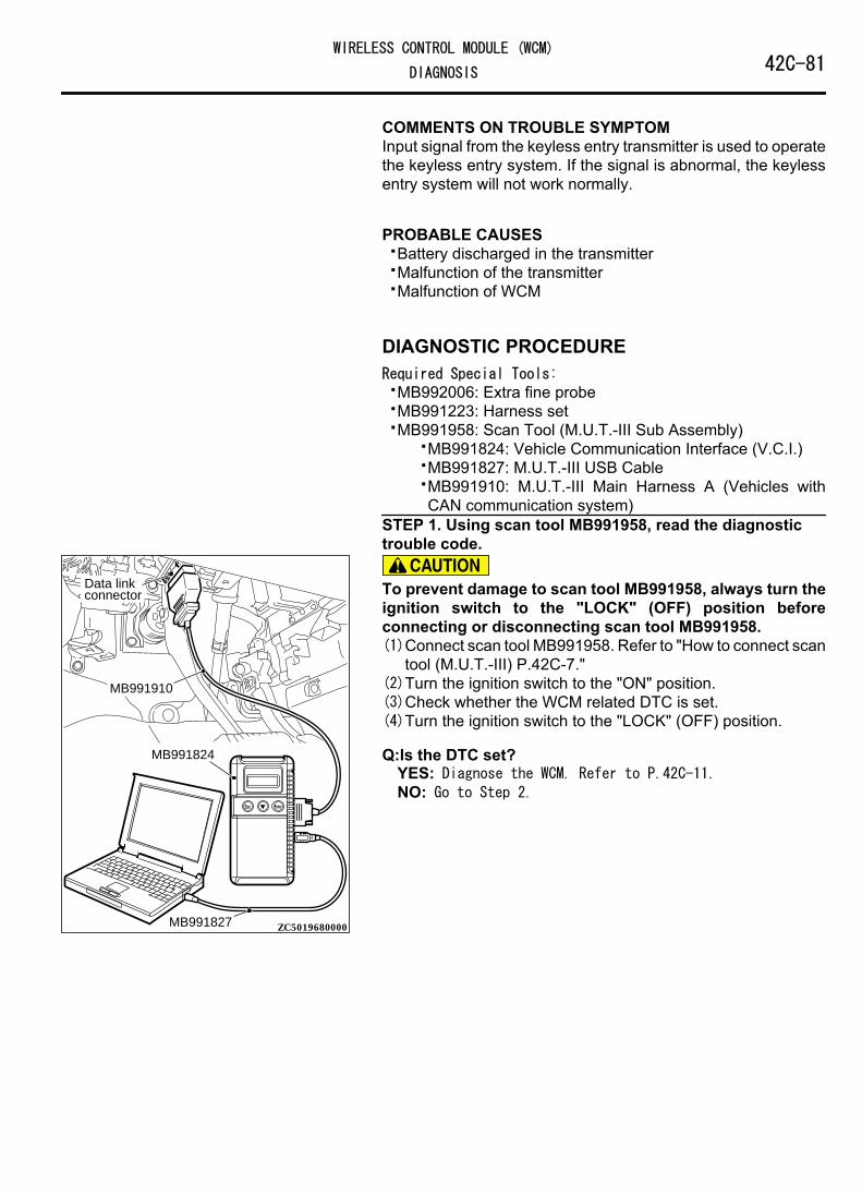
COMMENTS ON TROUBLE SYMPTOMInput signal from the keyless entry transmitter is used to operatethe keyless entry system. If the signal is abnormal, the keylessentry system will not work normally.
PROBABLE CAUSES⦆Battery discharged in the transmitter⦆Malfunction of the transmitter⦆Malfunction of WCM
DIAGNOSTIC PROCEDURERequired Special Tools:⦆MB992006: Extra fine probe⦆MB991223: Harness set⦆MB991958: Scan Tool (M.U.T.-III Sub Assembly)
⦆MB991824: Vehicle Communication Interface (V.C.I.)⦆MB991827: M.U.T.-III USB Cable⦆MB991910: M.U.T.-III Main Harness A (Vehicles with
CAN communication system)STEP 1. Using scan tool MB991958, read the diagnostictrouble code.
ZC501967AC404789
ZC5019680000
MB991824
MB991827
MB991910
Data linkconnector To prevent damage to scan tool MB991958, always turn the
ignition switch to the "LOCK" (OFF) position beforeconnecting or disconnecting scan tool MB991958.(1)Connect scan tool MB991958. Refer to "How to connect scan
tool (M.U.T.-III) P.42C-7."(2)Turn the ignition switch to the "ON" position.(3)Check whether the WCM related DTC is set.(4)Turn the ignition switch to the "LOCK" (OFF) position.
Q:Is the DTC set?YES: Diagnose the WCM. Refer to P.42C-11.NO: Go to Step 2.
WIRELESS CONTROL MODULE (WCM)42C-81DIAGNOSIS
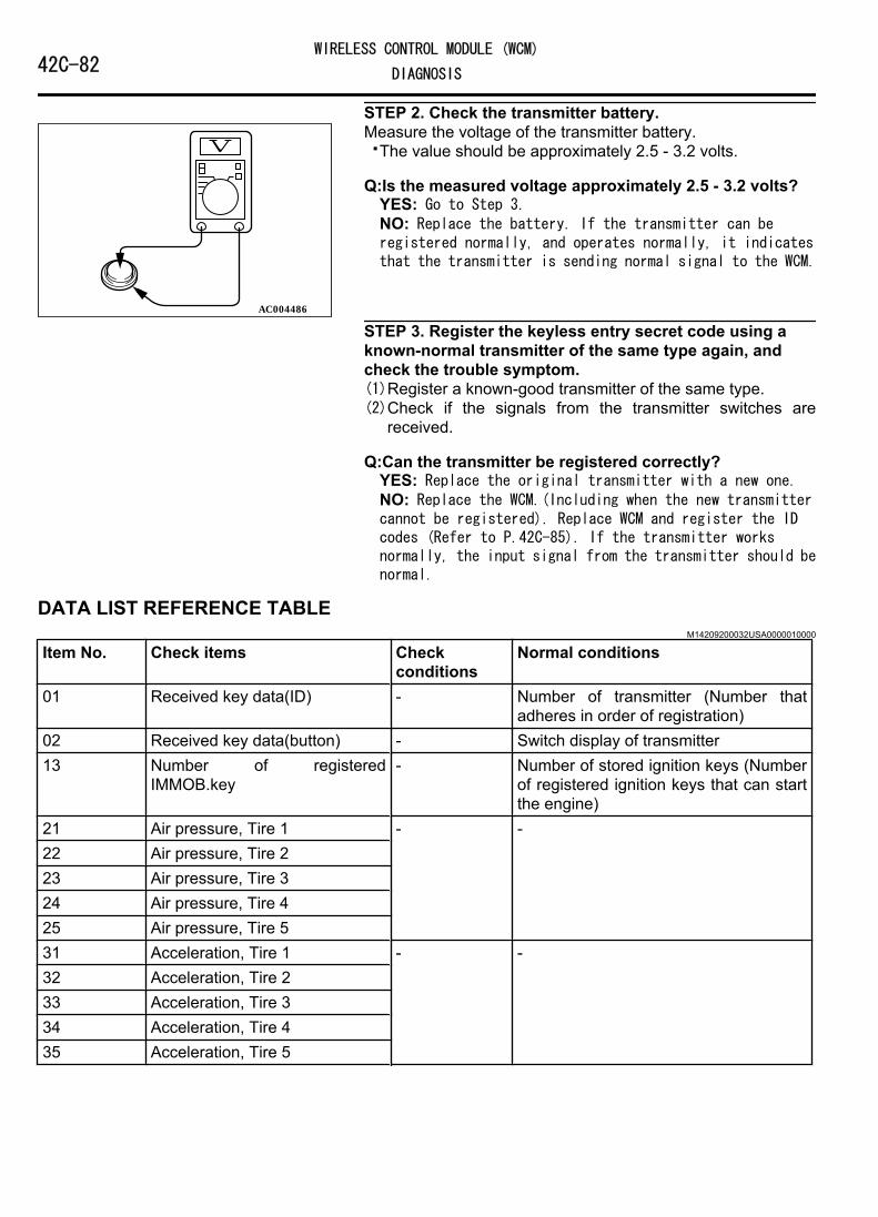
STEP 2. Check the transmitter battery.
AC004486
Measure the voltage of the transmitter battery.⦆The value should be approximately 2.5 - 3.2 volts.
Q:Is the measured voltage approximately 2.5 - 3.2 volts?YES: Go to Step 3.NO: Replace the battery. If the transmitter can beregistered normally, and operates normally, it indicatesthat the transmitter is sending normal signal to the WCM.
STEP 3. Register the keyless entry secret code using aknown-normal transmitter of the same type again, andcheck the trouble symptom.(1)Register a known-good transmitter of the same type.(2)Check if the signals from the transmitter switches are
received.
Q:Can the transmitter be registered correctly?YES: Replace the original transmitter with a new one.NO: Replace the WCM.(Including when the new transmittercannot be registered). Replace WCM and register the IDcodes (Refer to P.42C-85). If the transmitter worksnormally, the input signal from the transmitter should benormal.
DATA LIST REFERENCE TABLEM14209200032USA0000010000
Item No. Check items Checkconditions
Normal conditions
01 Received key data(ID) - Number of transmitter (Number thatadheres in order of registration)
02 Received key data(button) - Switch display of transmitter13 Number of registered
IMMOB.key- Number of stored ignition keys (Number
of registered ignition keys that can startthe engine)
21 Air pressure, Tire 1 - -22 Air pressure, Tire 223 Air pressure, Tire 324 Air pressure, Tire 425 Air pressure, Tire 531 Acceleration, Tire 1 - -32 Acceleration, Tire 233 Acceleration, Tire 334 Acceleration, Tire 435 Acceleration, Tire 5
42C-82WIRELESS CONTROL MODULE (WCM)
DIAGNOSIS

Item No. Check items Checkconditions
Normal conditions
36 Threshold of PRS. warning The tirepressure iswithin thespecified valuerange.
OFF
The tirepressure is notwithin thespecified valuerange.
ON
37 Threshold of PRS. warningrelease
The tirepressure iswithin thespecified valuerange.
ON
The tirepressure is notwithin thespecified valuerange.
OFF
38 Number of registered TPMS ID - Number of stored TPMS41 VSS Drive the
vehicleThe scan tool and the tachometerreadings are approximately the same
CHECK AT ECU TERMINALSM14209200046USA0000010000
ZC603896
C-29
0001
TerminalNo.
Check items Check conditions Normal conditions
1 - 5 - - -6 Power supply (Battery) Always Battery voltage7 Ground Always 0 V8 - - -9 Power supply (Ignition switch: IG1) Ignition switch: ON Battery voltage10 CAN L - -11 CAN H - -
WIRELESS CONTROL MODULE (WCM)42C-83DIAGNOSIS

SPECIAL TOOLSM14209200003USA0000010000
Tool Tool number andname
Supersession Application
MB991910
MB991826
YB9919580000
MB991911
MB991914
MB991824
MB991827
MB991825
Do not use
Do not use
a
b
c
d
e
f
g
MB991958a. MB991824b. MB991827c. MB991910d. MB991911e. MB991914f. MB991825g. MB991826M.U.T.-III subassemblya. Vehicle
communicationinterface (V.C.I.)
b. M.U.T.-III USBcable
c. M.U.T.-III mainharness A(Vehicles withCANcommunicationsystem)
d. M.U.T.-III mainharness B(Vehicles withoutCANcommunicationsystem)
e. M.U.T.-III mainharness C (forDaimler Chryslermodels only)
f. M.U.T.-IIImeasurementadapter
g. M.U.T.-III triggerharness
MB991824-KIT
NOTE: G: MB991826M.U.T.-III TriggerHarness is notnecessary whenpushing V.C.I. ENTERkey.
M.U.T.-III main harness A(MB991910) should be used.M.U.T.-III main harness B and Cshould not be used for thisvehicle.⦆Check of the diagnostic trouble
code and service data⦆Registration of ID codes
42C-84WIRELESS CONTROL MODULE (WCM)
SPECIAL TOOLS
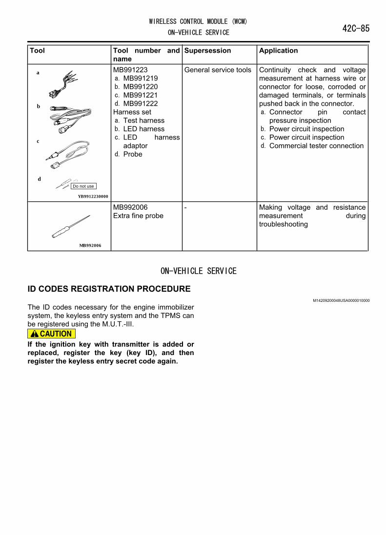
Tool Tool number andname
Supersession Application
YB9912230000
Do not use
a
b
c
d
MB991223a. MB991219b. MB991220c. MB991221d. MB991222Harness seta. Test harnessb. LED harnessc. LED harness
adaptord. Probe
General service tools Continuity check and voltagemeasurement at harness wire orconnector for loose, corroded ordamaged terminals, or terminalspushed back in the connector.a. Connector pin contact
pressure inspectionb. Power circuit inspectionc. Power circuit inspectiond. Commercial tester connection
MB992006
MB992006Extra fine probe
- Making voltage and resistancemeasurement duringtroubleshooting
ON-VEHICLE SERVICE
ID CODES REGISTRATION PROCEDUREM14209200048USA0000010000
The ID codes necessary for the engine immobilizersystem, the keyless entry system and the TPMS canbe registered using the M.U.T.-III.
If the ignition key with transmitter is added orreplaced, register the key (key ID), and thenregister the keyless entry secret code again.
WIRELESS CONTROL MODULE (WCM)42C-85ON-VEHICLE SERVICE

SUPPLY UNIT LIST FOR INDIVIDUAL KEYIgnition key (with transmitter)
NOTE: Blank key (It is the key thatcomes with the door service key set andthe glove box service key set. It canonly be used for locking and unlocking,and it cannot start the engine.)
ZC6037530000ZC6044010001
Blank key
KEY SUPPLY UNIT LIST FOR OTHER THAN INDIVIDUAL KEYFull service key set Handle lock service key
setDoor service key set Glove box service key
set
ZC6045380000
ZC6045400000ZC6045500000
ZC6045390000
NOTE:⦆When re-registering the key (key ID), all the keys
(key ID) registered before must be re-registeredbecause all of them will be erased.
⦆After registering the keys, make sure that theengine is started normally with all of the keysregistered.
42C-86WIRELESS CONTROL MODULE (WCM)
ON-VEHICLE SERVICE

ZC6037540000
Screen flow of M.U.T.-III
Key Registration (Barcode No.)*1
Key Registration*1
Key &KOS Key Registration*2
Cancel
OK
OK
OK
OK
OK
OK
OK
OK
OK
Key ID input
Execution check
Barcode No. registration completed
Special Function
KOS key registration Executing
KOS key registration completed
Registration result display
Key registration
Completion and an addition?
Special Function
Special Function
Refer to GROUP 00,How to Perform VIN Writing.
ENG key code Reg.*1*2
OK
Keyless ID Reg.*1
OK
Keyless ID registration Executing
Keyless ID registration Completed
OK
OK
Steering lock unit Reg.*2
OK
Password input
Steering lock unit registration
Executing
OK
Antenna select
Antennacommunicationtest Executing
NOTE: *1 Show the menu displayed when the vehicles for WCM.*2 Show the menu displayed when the vehicles for KOS.
Cancel
Steering lock unit registration
Completed
Password input
Password input Password input
Key registration
Completion and an addition?
Password input
Registration result display
Comm. Test*2
Antennacommunicationtest Completed
Additional key registration*1
Key(Barcode No.) &KOS Key Reg.*2
OK
OK
OK
OK
OK
OK
Key ID Input
Key registration password
The completion of barcode registration
KOS key registration password
KOS key registration completed
Registration result display
KOS key registration Executing
WIRELESS CONTROL MODULE (WCM)42C-87ON-VEHICLE SERVICE

ZC501967AC404789
ZC5019680000
MB991824
MB991827
MB991910
Data linkconnector
Connect the scan tool to the 16-pin data link connectoras follows.
NOTE: For details on how to use the scan tool,refer to the "M.U.T.-III User's Manual."1.Start the M.U.T.-III system on the PC and turn the
ignition switch to the "ON" position.
System Select
Select Model Year and System
System List Model Yea r
Vehicle In formatio n
Loading Option Setup
OPC With OptionOption Name
Model Name
Model Yea r
OUTLANDER
2007Model Code
Up to 2005 MY
From to 2006 M Y1
2
3
4
5
6
7
8
9
10
MPI/GDI/Diesel
KOS/IMMOBI/ Keyless/TPM S
AT/CVT/A-M T
ABS/ASC/ASTC
SAS
Multi Select 4WD
SRS Airbag
A/C
ETAC S
Meter
ZC6037850000OK button
2.Select "KOS/IMMO//Keyless/TPMS" button fromthe "System Select" screen. Then, select the
applicable option code item and push the OKbutton.
3.Select "Special Function" on the next screen.
System Select
Please select function.
Special Function
Key Regist ratio n Key Regist ration (Barcode N o.)
Keyless ID Reg . ENG Key Code Reg .
ZC6037870000
Vehicles for WCMK OS/IMMO/ K e yless/TPM S
Additional ke y regist ratio n
Tire Pressure Sensor ID Che ck
Tire Pressure Sensor ID Regist ratio n
Tire Pressure Sensor Che ck
4.Select the button of the operation to be performedfrom the "Special Function" screen.⦆"Key Registration": When the ignition key is
replaced or added as a single unit.⦆"Additional key registration": When the ignition
key is added as a single unit.⦆"Key Registration (Barcode No.)": When the
ignition key is replaced by the full service key setor the handle lock service key set is replaced bythe piece.
⦆"ENG key code Reg.": When the engine controlmodule is replaced.
⦆"Keyless ID Reg.": When the ignition key isreplaced or added.
⦆"Tire Pressure Sensor ID Registration": When theTPMS transmitter is replaced.
⦆"Tire Pressure Sensor Check": When the tirepressure sensor data is checked.
⦆"Tire Pressure Sensor ID Check": When the tirepressure sensor ID is checked.
NOTE:⦆For "Key Code Registration," refer to GROUP 00 -
Precautions before Service P.00-26.⦆For "Tire Pressure Sensor ID Registration," refer
to P.42C-92.⦆For "Tire Pressure Sensor Check," refer to P.
42C-94.⦆For "Tire Pressure Sensor ID Check," refer to P.
42C-94.
KEY REGISTRATION METHOD
42C-88WIRELESS CONTROL MODULE (WCM)
ON-VEHICLE SERVICE

ZC6038500000
OK button
1.When "Key registration" or "Additional keyregistration" screen is displayed, enter thepassword for the key registration and press the OKbutton. Then, "Executing!" is displayed and theregistration process starts.
NOTE:⦆If the wrong password is entered consecutively 5
times, the password entry for the key registrationwill be disabled for 16 minutes.
⦆The key registration cannot be cancelled duringthe operation.
ZC6038510000
Cancel button
2.When the key registration is completed,"Completed" is displayed. To register the next key,follow the message on the screen and press the OKbutton. Then, "Executing!" is displayed again andthe registration process for the next key starts. Tofinish the key registration, press the cancel button.
NOTE:⦆In order to register another key consecutively
after registering the first key, the ignition switchmust be turned to the ON position with the secondkey within 30 seconds after turning it to the"LOCK" (OFF) position with the first key.
⦆Up to eight keys can be registered.
KEY REGISTRATION (BARCODE NO.) METHOD
ZC6038520000
OK button
1.When "Key Registration (Barcode No.)" screen isdisplayed, enter the password for the keyregistration and press the OK button.
NOTE: If the wrong password is enteredconsecutively 5 times, the password entry forthe key registration will be disabled for 16minutes.
WIRELESS CONTROL MODULE (WCM)42C-89ON-VEHICLE SERVICE

ZC6038530000
ZC6038480000
Barcode
2.Follow the message on the screen to enter the barcode No., and then press the OK button.
3.When "Do you want to start registration?" isdisplayed, press the OK button to start theregistration, or press the Cancel button to cancelthe registration.
4."Key Registration was completed" is displayed.Press the OK button to finish the registration.
"KEYLESS ID REG." METHOD
ZC6037580000
OK button
1.On the "Keyless ID Reg." screen, enter thepassword and press the OK button.
2.Register within 1 minute and send the programmingpacket*to register the keyless ID. To registermultiple keys, register the next key within 1 minutefrom the registration operation of previous key.Complete the registration of necessary keys, thenpress the OK button to finish the keyless IDregistration.
NOTE:⦆Up to eight ignition keys can be registered.
⦆*: Programming packet sending procedureComplete the following steps 1 to 3 within fourseconds.
1. Press and hold both the lock and the unlockswitch for 1 second or longer.
2. Release both the lock and the unlock switchfor 0.5 second or longer.
3. Press the unlock switch.3.Push the OK button after "Keyless ID Registration
was finished." is displayed.
IMMOBI K e yles sK O S Special Function K e yless ID Regist ratio n
Item
Keyless ID Regist ratio n
Registered N o. Status
Pas swor d
Work of regist ratio n
Completed
Che c k the n umber of regist ration .
ZC6037570000
4.Check number of the keyless IDs registered.
42C-90WIRELESS CONTROL MODULE (WCM)
ON-VEHICLE SERVICE
KEYLESS ENTRY SYSTEM CHECKM14209200049USA0000010000
Check the keyless entry system function as described below. Ifit does not work, perform troubleshooting. Refer to P.42C-66.⦆Operate the transmitter to check that the doors and liftgate can
be locked and unlocked.⦆Operate the transmitter to check that the answerback function
works in response to door and liftgate locking/unlocking.
NOTE: The hazard and horn answerback setting can bechanged using the customization function. Confirm whichsetting is activated before performing these checks.Refer to P.42C-91.
INSPECTION OF KEYLESS ENTRY TIMER LOCKFUNCTION
M14209200051USA0000010000
Attempt to unlock the doors and the liftgate by using thetransmitter. If the doors and the liftgate are not locked within 30seconds, carry out diagnosis. Note that the doors and the liftgatewill not be locked if the ignition key is inserted within the 30-second period, one of the doors or the liftgate is opened. Referto P.42C-66.NOTE: The operation time of the keyless entry timer lockfunction can be set using the customization function.Confirm the operation time before performing the diagnosis.Refer to P.42C-91.
CONFIGURATION FUNCTIONM14209200052USA0000010000
Using M.U.T.-III, the following functions can becustomized. The programmed information is heldeven when the battery is disconnected.Adjustmentitem (scan toolMB991958display)
Adjustment item Adjusting contents(scan tool MB991958display)
Adjusting contents
Hazard answerback
Adjustment of thenumber of keylesshazard warning lightanswer backflashes
Lock:1, Unlock:2 LOCK: Flashes once, UNLOCK: Flashestwice (default)
Lock:1, Unlock:0 LOCK: Flashes once, UNLOCK: No flashLock:0, Unlock:2 LOCK: No flash, UNLOCK: Flash twiceLock:2, Unlock:1 LOCK: Flash twice, UNLOCK: Flash onceLock:2, Unlock:0 LOCK: Flash twice, UNLOCK: No flashLock:0, Unlock:1 LOCK: No flash, UNLOCK: Flash onceLock:0, Unlock:0 Without function
Dome lightdelay timer withdoor
Adjustment ofinterior light delayshutdown time
0sec 0 second (no delay shutdown time)7.5sec 7.5 seconds
WIRELESS CONTROL MODULE (WCM)42C-91ON-VEHICLE SERVICE
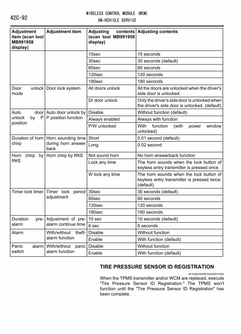
Adjustmentitem (scan toolMB991958display)
Adjustment item Adjusting contents(scan tool MB991958display)
Adjusting contents
15sec 15 seconds30sec 30 seconds (default)60sec 60 seconds120sec 120 seconds180sec 180 seconds
Door unlockmode
Door lock system All doors unlock All the doors are unlocked when the driver'sside door is unlocked.
Dr door unlock Only the driver's side door is unlocked whenthe driver's side door is unlocked. (default)
Auto doorunlock by Pposition
Auto door unlock byP position function
Disable Without function (default)Always enabled Always with functionP/W unlocked With function (with power window
unlocked)Duration of hornchirp
Horn sounding timeduring horn answerback
Short 0.01 second (default)Long 0.02 second
Horn chirp byRKE
Horn chirp by RKE Not sound horn No horn answerback functionLock any time The horn sounds when the lock button of
keyless entry transmitter is pressed once.W lock any time The horn sounds when the lock button of
keyless entry transmitter is pressed twice.(default)
Timer lock timer Timer lock periodadjustment
30sec 30 seconds (default)60sec 60 seconds120sec 120 seconds180sec 180 seconds
Duration pre-alarm
Adjustment of pre-alarm continue time
10 sec 10 seconds (default)6 sec 6 seconds
Alarm With/without theft-alarm function
Disable Without functionEnable With function (default)
Panic alarmswitch
With/without panicalarm function
Disable Without functionEnable With function (default)
TIRE PRESSURE SENSOR ID REGISTRATIONM14209200068USA0000010000
When the TPMS transmitter and/or WCM are replaced, execute"Tire Pressure Sensor ID Registration." The TPMS won'tfunction until the "Tire Pressure Sensor ID Registration" hasbeen complete.
42C-92WIRELESS CONTROL MODULE (WCM)
ON-VEHICLE SERVICE

Required Special Tools:⦆MB991958: Scan Tool (M.U.T.-III Sub Assembly)
⦆MB991824: Vehicle Communication Interface (V.C.I.)⦆MB991827: M.U.T.-III USB Cable⦆MB991910: M.U.T.-III Main Harness A
Register the tire pressure sensor IDs as described in theprocedure below.
To prevent damage to scan tool MB991958, always turn theignition switch to the "LOCK" (OFF) position beforeconnecting or disconnecting scan tool MB991958.1.Connect scan tool MB991958 to the data link connector.2.Turn the ignition switch to the "ON" position.3.Select "Interactive Diagnosis" from the start-up screen.4.Select "System select."5.Select "Special Function."6.Select "Tire Pressure Sensor ID Registration."7.Select "4tires ID Reg. (Change tire PRS.)" and start the tire
pressure sensor ID registration.
Register all tire pressure sensor IDs within twenty minutes.8."4 SNSR ID Registration Do you want to start? Note Finish ID
Registration within 20 minutes." is displayed. Then, press"OK."
9.Decrease the tire pressure to 174 kPa or less, and register theTPMS transmitter ID code of each wheel to WCM.
NOTE:⦆On completion of the TPMS transmitter ID code registration,
the TPMS transmitter ID code is displayed on the M.U.T.-IIIscreen.
⦆It may take approximately one minute for the ID code to bedisplayed on the M.U.T.-III screen after the tire pressure isreduced.
⦆If the ID code is not displayed, reduce the tire pressureanother 20 kPa or more. If the ID code is not displayed yet,rotate the tire to displace the TPMS transmitter, and reducethe tire pressure 20 kPa or more again.
⦆You can start out the following operations from any TPMStransmitter. The tire pressure sensor ID registration has noorder.
10."4 SNSR ID Registration Completed." is displayed. Then,select "OK."
NOTE: The TPMS indicator illuminates for tire pressurealarm.
11.After tire pressure sensor ID registration, turn the ignitionswitch to the "LOCK" (OFF) position.
12.Remove scan tool MB991958.
WIRELESS CONTROL MODULE (WCM)42C-93ON-VEHICLE SERVICE

TIRE PRESSURE SENSOR CHECKM14209200069USA0000010000
Required Special Tools:⦆MB991958: Scan Tool (M.U.T.-III Sub Assembly)
⦆MB991824: Vehicle Communication Interface (V.C.I.)⦆MB991827: M.U.T.-III USB Cable⦆MB991910: M.U.T.-III Main Harness A
Check the condition of the tire pressure sensor as describedbelow.
To prevent damage to scan tool MB991958, always turn theignition switch to the "LOCK" (OFF) position beforeconnecting or disconnecting scan tool MB991958.1.Connect scan tool MB991958 to the data link connector.2.Turn the ignition switch to the "ON" position.3.Select "Interactive Diagnosis" from the start-up screen.4.Select "System select."5.Select "Special Function."6.Select "Tire Pressure Sensor Check."7."Tire Pressure Sensor Check. Do you want to start?" is
displayed. Then, select "OK."8.Change the pressure of tire to be checked for 20 kPa or more.
(The tire pressure can either be decreased or increased.)9.Check the data on the PC display.
NOTE:⦆It may take approximately one minute for the ID code to be
displayed on the M.U.T.-III screen after the tire pressure ischanged.
⦆If the ID code is not displayed, change the tire pressureanother 20 kPa or more. If the ID code is not still displayed,rotate the tire to displace the TPMS transmitter, and changethe tire pressure 20 kPa or more again.
10.After tire pressure sensor check, turn the ignition switch tothe "LOCK" (OFF) position.
11.Remove scan tool MB991958.
TIRE PRESSURE SENSOR ID CHECKM14209200070USA0000010000
Required Special Tools:⦆MB991958: Scan Tool (M.U.T.-III Sub Assembly)
⦆MB991824: Vehicle Communication Interface (V.C.I.)⦆MB991827: M.U.T.-III USB Cable⦆MB991910: M.U.T.-III Main Harness A
Check the tire pressure sensor IDs, which is registered in theTPMS receiver, as described below.
42C-94WIRELESS CONTROL MODULE (WCM)
ON-VEHICLE SERVICE

To prevent damage to scan tool MB991958, always turn theignition switch to the "LOCK" (OFF) position beforeconnecting or disconnecting scan tool MB991958.1.Connect scan tool MB991958 to the data link connector.2.Turn the ignition switch to the "ON" position.3.Select "Interactive Diagnosis" from the start-up screen.4.Select "System select."5.Choose "TPMS" from the "CHASSIS" tab.6.Select "MITSUBISHI."7.Select "Special Function."8.Select "Tire Pressure Sensor ID Check."9.Check the tire pressure sensor IDs on the PC display.10.After tire pressure sensor ID check, turn the ignition switch
to the "LOCK" (OFF) position.11.Remove scan tool MB991958.
FROM SCAN TOOL MB99158 DIAGNOSIS SCREENYou can check the tire pressure sensor ID on the diagnosisscreen as described below.1.Operate scan tool MB991958 as follows:
⦆Press "Special" button on the diagnosis screen.⦆Select "Tire Pressure Sensor ID Check" from the "Special
Function" menu.2.Check the tire pressure sensor IDs on the PC display.3.After tire pressure sensor ID check, turn the ignition switch to
the "LOCK" (OFF) position.4.Remove scan tool MB991958.
WCM
REMOVAL AND INSTALLATIONM14209200054USA0000010000
⦆To remove the driver airbag module, refer toGROUP 52B - Service Precautions P.52B-28and Air Bag Module(s) and ClockSpring P.52B-329.
⦆When WCM has been replaced, all key ID codesshould be registered, referring to the ID coderegistration necessity judgment table P.42C-8.
Pre-removal operation⦆Lower panel and steering column cover removal (Refer to
GROUP 52A - Instrument Panel Assembly P.52A-2.)⦆Clock spring column switch assembly removal (Refer to
GROUP 37 - Steering Shaft P.37-23or GROUP 52B - Air BagModule(s) and Clock Spring P.52B-329.)
Post-installation operation⦆Clock spring column switch assembly installation (Refer to
GROUP 37 - Steering Shaft P.37-23or GROUP 52B - Air BagModule(s) and Clock Spring P.52B-329.)
⦆Lower panel and steering column cover installation (Refer toGROUP 52A - Instrument Panel Assembly P.52A-2.)
WIRELESS CONTROL MODULE (WCM)42C-95WCM

ZC600980
1
2
AA002.0 ± 0.5 N·m 18 ± 4 in-lb
Removal steps1. Key ring illumination light
Removal steps>>A<< 2. WCM
INSTALLATION SERVICE POINT
>>A<< WCM INSTALATIONCheck that the top claw of WCM is fixed securely to the boss ofsteering lock and the antenna is not floated on the key cylinder.
TRANSMITTER
DISASSEMBLY AND ASSEMBLYM14209200056USA0000010000
Post-installation operation⦆Transmitter operation check
42C-96WIRELESS CONTROL MODULE (WCM)
TRANSMITTER

ZC6002201
2
3
4
0000
Disassembly steps<<A>> 1. Upper cover
2. Transmitter assembly<<B>> >>A<< 3. Battery
Disassembly steps4. Master key
DISASSEMBLY SERVICE POINTS
<<A>> UPPER COVER REMOVAL
To prevent damage to the transmitter, wrap a flat-tippedscrewdriver with protective tape before prying.
ZC600348
Transmitter
Flat-tipped screwdriver 0000
Insert a flat-tipped screwdriver in the area shown, and removethe upper cover by prying it with the screwdriver.
WIRELESS CONTROL MODULE (WCM)42C-97TRANSMITTER

<<B>> BATTERY REMOVAL
⦆Do not allow water or dust to enter the inside of thetransmitter assembly when it is open. Also, do not touchthe precision electronic device.
⦆To prevent damage to the transmitter assembly, wrap aflat-tipped screwdriver with protective tape before prying.
ZC600349
Transmitter assembly
Flat-tipped screwdriver 0000
Insert a flat-tipped screwdriver in the area shown, and removethe battery by prying it with the screwdriver.
ASSEMBLY SERVICE POINT
>>A<< BATTERY INSTALLATION
Do not allow water or dust to enter the inside of thetransmitter assembly when it is open. Also, do not touch theprecision electronic device.
ZC600350
+
Master key side
Upper cover side
Battery
Transmitter assembly
–
0000
Install a new battery to the transmitter assembly with its (+) sidefacing towards the master key side.
Battery required for replacement: Coin type batteryCR1620
42C-98WIRELESS CONTROL MODULE (WCM)
TRANSMITTER

INSPECTIONM14209200057USA0000010000
TRANSMITTER BATTERY CHECK
AC004486
Measure the voltage of the battery. If the voltage of the batteryis not within the standard value, replace the battery.
Standard value:2.5 - 3.2 V
TPMS TRANSMITTER
REMOVAL AND INSTALLATIONM14209200072USA0000010000
⦆Ensure valve cap is always in place except whenadjusting tire pressure.
⦆If the valve core and valve cap are replaced, usea genuine replacement part. The valve core issimilar to a conventional one, but uses nickelplating to avoid corrosion.
⦆Replace the valve stem grommet and washerwith a new one every five years or when the tireis replaced.
⦆Do not drop the TPMS transmitter from heightgreater than 1 meter (3.3 feet).
⦆Do not expose the TPMS transmitter toextraneous magnetic fields.
⦆TPMS transmitter should not be stored attemperatures above 80°C (176°F).
⦆TPMS transmitter should not be exposed totemperatures above 100°C (212°F).
⦆If the TPMS transmitter is replaced, execute"Tire Pressure Sensor ID Registration" on scantool MB99158 "Special Function."
Pre-removal Operation⦆Wheel and Tire Removal
Post-installation Operation⦆Wheel and Tire Installation⦆Tire Pressure Sensor ID Registration If a new TPMS transmitter is installed (Refer to P.42C-92.)⦆After the tire pressure sensor ID registration, check that the TPMS warning light does not illuminate
or flash.
WIRELESS CONTROL MODULE (WCM)42C-99TRANSMITTER

ZC6045420000
1
23 4 N
8.0 ± 0.5 N·m 71 ± 4 in-lb
0.25 N·m 2.5 in-lb
5
REMOVAL STEPS<<A>> 1. VALVE CAP<<A>> 2. VALVE NUT
· LET TPMS TRANSMITTERFALL INTO TIRE
· TIRE BEAD<<B>> 3. TPMS TRANSMITTER<<C>> 4. GROMMET<<C>> 5. WASHER
INSTALLATION STEPS>>A<< 5. WASHER
INSTALLATION STEPS>>A<< 4. GROMMET>>A<< 3. TPMS TRANSMITTER>>A<< 2. VALVE NUT>>B<< · TIRE BEAD MOUNTING>>C<< · TIRE PRESSURE INFLATION>>C<< · VALVE NUT RETIGHTENING
1. VALVE CAP
REMOVAL SERVICE POINTS
<<A>> VALVE CAP/VALVE NUT REMOVAL
Ensure valve cap is always in place except when adjustingtire pressure.1.Remove the valve cap.2.Rotate tire so that valve stem is in the 6 o’clock position.3.Use a long-reach 17.2 mm (0.68 inch) socket to unscrew the
valve nut and remove it. Slowly push valve stem into tire sothat tire pressure is relieved.
4.Once tire pressure is relieved, let TPMS transmitter into tire.
42C-100WIRELESS CONTROL MODULE (WCM)
TPMS TRANSMITTER

<<B>> TPMS TRANSMITTER REMOVAL
ZC6008320000
TPMS Transmitter
1.Place on tire changing machine and break both tire beadsensuring that the transmitter remains in the bottom of the tire.
Be careful not to damage the TPMS transmitter.2.Lubricate tire well and remove outer side of the tire.3.Reach inside the tire and remove the TPMS transmitter.4.Remove tire from rim using proper tire changing equipment
procedures.
<<C>> GROMMET/WASHER REMOVAL
⦆Do not vary the angle of valve except at mounting on therim. If varying the angle over and over, it may causebreakage of antenna plate resulting in the failure oftransmitter.
⦆Use a soft tool to remove the grommet and washer toprevent scratching the valve of the TPMS transmitter.
Remove the grommet and washer from the TPMS transmitter.
INSTALLATION SERVICE POINTS
>>A<< GROMMET/WASHER/TPMS TRANSMITTER/VALVENUT INSTALLATION
When installing a new grommet and washer, make sure tosupport the valve stem base with a thumb so that there isno movement of the stem. Otherwise, the stem mayprotrude resulting in the breakage of antenna plate.1.Install a new grommet and washer to the TPMS transmitter.
ZC6045430000
TPMS transmitter
Grommet
Valve nut
Holes
Washer⦆Visually check that TPMS transmitter is not deformed or
damaged.⦆When installing the TPMS transmitter, be sure the rim,
grommet and valve nut are clean.⦆Ensure the grommet is located inside the valve hole
before installing the valve nut.⦆While installing the valve nut, push the transmitter to
maintain the lower lip of the transmitter case is in contactwith the rim without clearance.
⦆While installing the valve nut, ensure the tool is keptaligned to the valve and the valve hole.
⦆After installing the valve nut, check that the grommet iscompressed and washer is bend.
WIRELESS CONTROL MODULE (WCM)42C-101TPMS TRANSMITTER

2.Mount TPMS transmitter valve through rim hole as illustrated.Pressure holes in the transmitter case should face away fromcenter of rim. Tighten valve nut finger tight, then slowly torquethe valve nut to 8.0 ± 0.5 N·m (71 ± 4 in-lb).
Install the TPMS transmitter correctly. If the TPMStransmitter is installed incorrectly, it may not workcorrectly, or become damaged when the tire is installed.3.Check that the TPMS transmitter is correctly assembled
(Refer to illustration).⦆Lower lip of the TPMS transmitter case is touching the rim
after torquing.
>>B<< TIRE BEAD MOUNTING
ZC604545 AA00
1.Put the tire on the rim, so that the cross point of the belt withthe rim is approximately 20 cm (7.9 inch) away from the valve
ZC604546AA00
2.Engage the shoe and make sure that 20 cm (7.9 inch) ismaintained between the cross point and the valve. The arrowshows the direction of rotation of the wheel.
ZC604547AA00
3.Turn the wheel in order to engage all the first side of the tire.
NOTE: The standard shoes can pass over the sensor withoutdamaging it.
42C-102WIRELESS CONTROL MODULE (WCM)
TPMS TRANSMITTER

ZC604548AA00
4.Put the second side of the tire in position, so that the crosspoint of the belt with the rim is approximately 20 cm (7.9 inch)away from the valve. the curved arrow shows the direction ofrotation of the wheel.
ZC604549AA00
5.Turn the wheel in order to engage all of the second side of thetire.
NOTE: The standard shoes can pass over the sensor withoutdamaging it.
>>C<< TIRE PRESSURE INFLATION/VALVE NUTRETIGHTENING
After tire inflation, retighten the valve nut 8.0N·m (71 inchpounds). This is necessary, because the TPMS transmitteris secured to the wheel with the valve nut and rubbergrommet. The rubber grommet will be depressed by tirepressure or deteriorate over a period of time, which requiresthe valve nut to be retightened.Inflate tire to required pressure, then retorque the valve nut to8.0 N·m (71 inch pounds).
WIRELESS CONTROL MODULE (WCM)42C-103TPMS TRANSMITTER

MEMO
42C-104WIRELESS CONTROL MODULE (WCM)