wireless based service to monitor automatic …
TRANSCRIPT

9
Int. J. Elec&Electr.Eng&Telecoms. 2015 Sumbul Perveen et al., 2015
WIRELESS BASED SERVICE TO MONITORAUTOMATIC IRRIGATION SYSTEM FOR
AGRICULTURE FIELD
S Saravana1, Sumbul Perveen2* and Akashdeep2
*Corresponding Author: Sumbul Perveen,[email protected]
Alternative energy technologies, like solar based energy generation systems, are receivingnational and worldwide attention owing to the rising rate of consumption of nuclear and fossilfuels. In particular, drivers for solar renewable energy systems are the environmental benefits(reduction of carbon emissions due to the use of renewable energy sources and the efficientuse of fossil fuels), reduced investment risk, fuel diversification, and energy autonomy, increasedenergy efficiency (less line losses) as well as potential increase of power quality and reliabilityand in certain cases, potential grid expansion deferral due to the possibility of generation closeto demand. Therefore, solar power has been used for recharging of the battery for driving thepump. Wireless sensors has been established in filed to record the field status through the PICmicrocontroller wireless technology like GPRS techniques has been used for the informing theuser about the field parameters which avoid the problem of physical monitoring services of thefield. A relay which is an electronic switch is used for switching the operational mode of thepump.
Keywords: Solar energy, GPRS module, Wireless sensors, PIC microcontroller, Realy switch
INTRODUCTIONRenewable source of energy are gainingattention nowdays. So its use in the monitoringof the agriculture field is also driving attention.Previously, parameters of the agriculture fieldare handled manually by the farmers. Noautomatic technique was available which lead
ISSN 2319 – 2518 www.ijeetc.comVol. 4, No. 3, July 2015
© 2015 IJEETC. All Rights Reserved
Int. J. Elec&Electr.Eng&Telecoms. 2015
1 Professor, Electronics and Telecommunications, Bharath University, Chennai, Tamil Nadu 600073, India.2 UG Research Scholar Student Potential Division, Electronics and Telecommunication, Bharath University, Chennai, Tamil Nadu
600073, India.
to the wastage of water during irrigationsometimes. The wired lines used toestablished which create diff iculty formonitoring during night or when power isswitched off. A new system to check theagriculture field parameter automatically isdesigned using wireless sensors which is
Research Paper

10
Int. J. Elec&Electr.Eng&Telecoms. 2015 Sumbul Perveen et al., 2015
charged by a group of photovoltaic cells, i.e.,solar power. A threshold value is set for thesensors and if the value goes beyond thethreshold value, the status will be updated tothe farmer through GPRS module, i.e., GSMby sending the text messages to the farmer(Chandrika Chanda and Surbhi Agarwal,2012). For transmitting the data betweensystem and the user, microcontroller isinterfaced with GSM. It has sim storagecapacity which store the control instructionsand status of the field (Godfrey Mills, 2013).The operational mode of the water pump iscontrol by the relay which is an electronicallyoperated switch. The statuse are displayed bythe LCD.
OVERVIEW OF THE SYSTEMAn irrigation system uses PIC16F877amicrocontroller, the other parts of the hardware
system are power supply, sensors, pumpswitching system, GSM communicationmodule. A communication module transfer thedata between the user and system. The logicof the operation for the controlling of theirrigation system is implemented onmicrocontroller (Deepti Bansal, 2013).
The sensors like temperature sensor, waterlevel sensor, humidity sensor is being used.The series of LM34 sensors is used astemperature sensors in which externalcalibrations not required and its output valueis proportional to the Fahrenheit value. Theseries of aqua plumb water level sensors isbeing used which is used to measure the waterlevel of the tank, reservoir, etc.
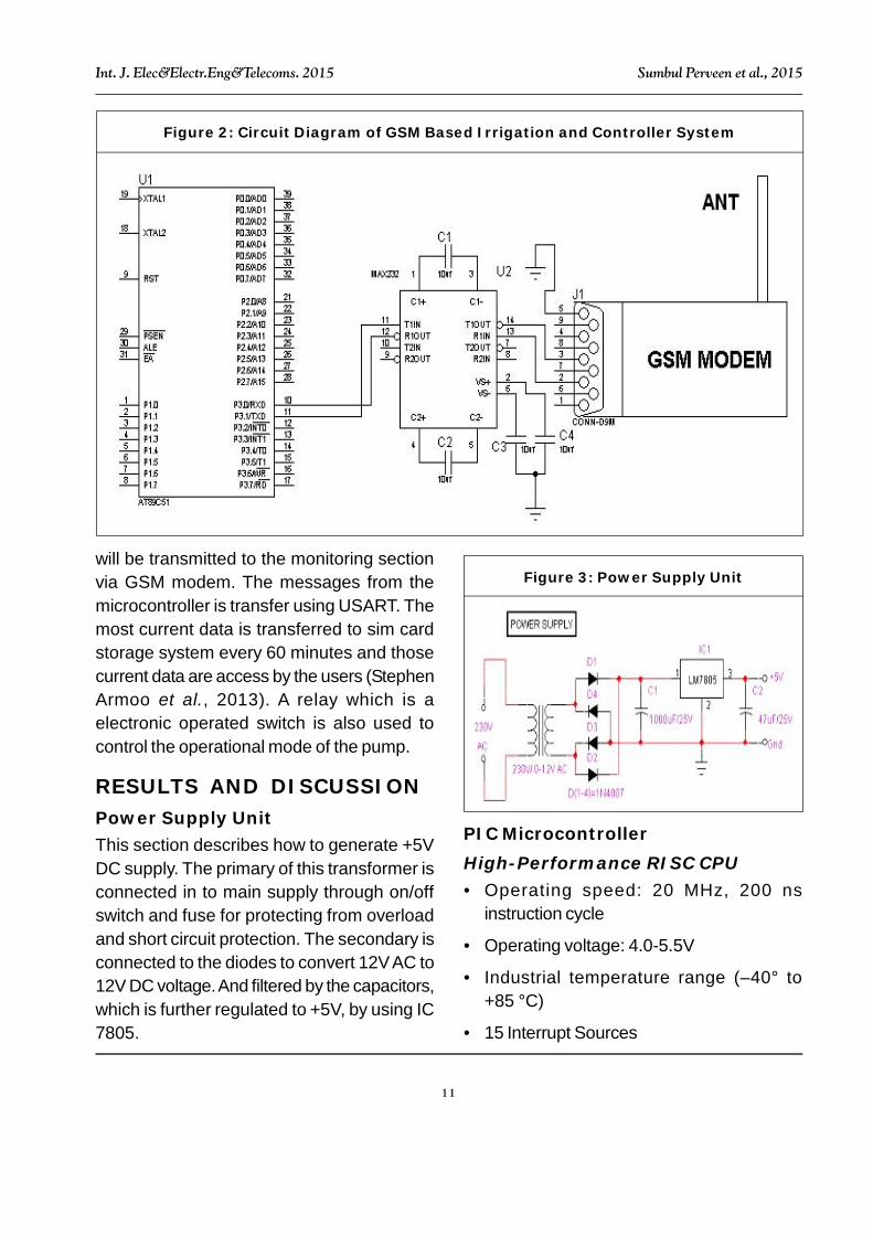
To transmit the data betweenmicrocontroller and GSM module MAX232 isused which convert the voltage level. Message
Figure 1: Block Diagram of the Controller System
11
Int. J. Elec&Electr.Eng&Telecoms. 2015 Sumbul Perveen et al., 2015
will be transmitted to the monitoring sectionvia GSM modem. The messages from themicrocontroller is transfer using USART. Themost current data is transferred to sim cardstorage system every 60 minutes and thosecurrent data are access by the users (StephenArmoo et al., 2013). A relay which is aelectronic operated switch is also used tocontrol the operational mode of the pump.
RESULTS AND DISCUSSIONPower Supply UnitThis section describes how to generate +5VDC supply. The primary of this transformer isconnected in to main supply through on/offswitch and fuse for protecting from overloadand short circuit protection. The secondary isconnected to the diodes to convert 12V AC to12V DC voltage. And filtered by the capacitors,which is further regulated to +5V, by using IC7805.
PIC MicrocontrollerHigh-Performance RISC CPU• Operating speed: 20 MHz, 200 ns
instruction cycle
• Operating voltage: 4.0-5.5V
• Industrial temperature range (–40° to+85 °C)
• 15 Interrupt Sources
Figure 2: Circuit Diagram of GSM Based Irrigation and Controller System
Figure 3: Power Supply Unit

12
Int. J. Elec&Electr.Eng&Telecoms. 2015 Sumbul Perveen et al., 2015
• 35 single-word instructions
• All single-cycle instructions except forprogram branches (two-cycle)
Special Microcontroller Features• Flash Memory: 14.3 Kbytes (8192 words)
• Data SRAM: 368 bytes
• Data EEPROM: 256 bytes
• Self-reprogrammable under softwarecontrol
• In-Circuit Serial Programming via two pins(5V)
• Watchdog Timer with on-chip RC oscillator
• Programmable code protection
• Power-saving Sleep mode
• Selectable oscillator options
• In-Circuit Debug via two pins
Peripheral Features• 33 I/O pins; 5 I/O ports
• Timer0: 8-bit timer/counter with 8-bitprescaler
• Timer1: 16-bit timer/counter with prescaler
– Can be incremented during Sleep viaexternal crystal/clock
• Timer2: 8-bit timer/counter with 8-bit periodregister, prescaler and postscaler
• Two Capture, Compare, PWM modules
– 16-bit Capture input; max resolution 12.5ns
– 16-bit Compare; max resolution 200 ns
– 10-bit PWM
• Synchronous Serial Port with two modes:
– SPI Master
– I2C Master and Slave
• USART/SCI with 9-bit address detection
• Parallel Slave Port (PSP)
– 8 bits wide with external RD, WR and CScontrols
• Brown-out detection circuitry for Brown-OutReset
Analog Features• 10-bit, 8-channel A/D Converter
• Brown-Out Reset
• Analog Comparator module
– 2 analog comparators
– Programmable on-chip voltagereference module
– Programmable input multiplexing fromdevice inputs and internal VREF
– Comparator outputs are externallyaccessible
Figure 4: PIN Diagram

13
Int. J. Elec&Electr.Eng&Telecoms. 2015 Sumbul Perveen et al., 2015
Memory of the PIC16F877 Dividedinto 3 Types of Memories• Program Memory—A memory that contains
the program(which we had written), afterwe've burned it. As a reminder, ProgramCounter executes commands stored in theprogram memory, one after the other.
• Data Memory—This is RAM memory type,which contains a special registers like SFR(Special Faction Register) and GPR(General Purpose Register). The variablesthat we store in the Data Memory during theprogram are deleted after we turn of themicro.
These two memories have separated databuses, which makes the access to eachone of them very easy.
• Data EEPROM (Electrically ErasableProgrammable Read-Only Memory)—Amemory that allows storing the variables asa result of burning the written program.
Each one of them has a different role.Program Memory and Data Memory twomemories that are needed to build a program,and Data EEPROM is used to save data afterthe microcontroller is turn off.
Program Memory and Data EEPROM theyare non-volatile memories, which store theinformation even after the power is turn off.These memories called Flash Or EEPROM.In contrast, Data Memory does not save theinformation because it needs power in orderto maintain the information stored in the chip.
GSM MODEMA GSM modem is a wireless modem thatworks with a GSM wireless network. The maindifference between them is that a dial-up
modem sends and receives data through afixed telephone line while a wireless modemsends and receives data through radio waves.The working of GSM modem is based oncommands, the commands always start withAT (which means Attention) and finish with a<CR> character. For example, the dialingcommand is ATD<number>;ATD3314629080; here the dialing commandends with semicolon.
The AT commands are given to the GSMmodem with the help of PC or controller. TheGSM modem is serially interfaced with thecontroller with the help of MAX 232. Here max232 acts as driver which converts TTL levelsto the RS 232 levels. For serial interface GSMmodem requires the signal based on RS 232levels.
TEMEPRATURE SENSORSA series of LM34 sensors is being used as atemperature sensors. It is a precisionintegrated circuit temperature in which externalcalibration is not required. The output voltageis proportional to the Fahrenheit value.
Figure 5: Circuit Diagram for the LM34Temperature Sensor Functional Module

14
Int. J. Elec&Electr.Eng&Telecoms. 2015 Sumbul Perveen et al., 2015
WATER LEVEL SENSORSA series of aqua plumb is being used as waterlevel sensors. The reading is reported backas a analog voltage ranging from 0V to 3Vwhere 0V indicate the sensor not beingsubmerged while 3V indicate the maximumliquid level. The normal power mode for the
operation is 1.2 mA, so this system can beloop powered in 4-20 mA current loops. Duringcalibration mode the sensor consumes up to20 mA, but this is only used during calibrationfor the initial setup.
RELAYAn electronic operated switch. Electric currentthrough the coil of the relay creates a magneticfield which attracts a lever and changes theswitch contacts. The coil current can be on oroff so relays have two switch positions andthere are double-throw (changeover) switches.The P0_0, P0_1, P0_2 and P0_3 pin ofcontroller is assumed as data transmit pins tothe relay through relay driver ULN 2003. ULN2003 is just like a current driver.
LCDThe most commonly used Character basedLCDs are based on Hitachi’s HD44780controller or other which are compatible withHD44580. In this, we will discuss about
Figure 6: Labeled Picture of theTemperature Sensor Circuit Functional
Module
Figure 7: A Relay in PIN Diagram

15
Int. J. Elec&Electr.Eng&Telecoms. 2015 Sumbul Perveen et al., 2015
character based LCDs, their interfacing withvarious microcontrollers, various interfaces (8-bit/4-bit), programming.
SOLAR PANELSolar in the form of solar electric panel, alsoknown as photovoltaic modules (or PVmodules), convert sunlight into electricity. Thesolar energy is used to reduce the powerconsumption of the battery and introduce theenvironmental friendly technique.
CONCLUSIONThe technique of monitoring the irrigation ofthe agriculture field through automation is foundto be cost effective, fast response , savesenergy and time. It reduces the wastage ofwater resources during irrigation and also insome areas provide sustainable use of waterwhere the shortage of water occurs. The useof solar power in the irrigation reduces theconsumption of electric power which can beexpensive. The intimation of the status of fieldparameter to the user through GSM lessen thedifficulty of the farmer for the manually handlingof field. Therefore, this kind of irrigation systemis used for contracting the wastage of theresources.
ACKNOWLEDGMENTI would like to thank esteemed BharathUniversity-R&D Students Potential Division ofElectronics and Telecommunication
engineering, research lab mentor Dr MPoonavaika and Director of Computing andCommunication Network research lab.
REFERENCES1. Aniket H Hade and Sengupta M K (2014),
“Automatic Control of Drip IrrigationSystem & Monitoring of Soil by Wireless”,Vol. 7, No. 4, Ver. III, pp. 57-61.
2. Chandrika Chanda, Surbhi Agarwal andEr B Persis Urbana Ivy (2012), “A Surveyof Automated GSM Based IrrigationSystems”, Vol. 2, No. 10.
3. Deepti Bansal and Reddy S R N (2013),“WSN Based Closed Loop AutomaticIrrigation System”, Department ofElectronics and Communication IGIT, IPUniversity, Delhi, India.
4. Godfrey A Mills, Stephen K Armoo,Agyeman K Rockson, Robert A Sowahand Moses A Acquah (2013), “GSMBased Irrigation Control and MonitoringSystem”, Vol. 5, No. 7.
5. Jyothipriya A N, Saravanabava T P (2013),“Design of Embedded Systems for DripIrrigation Automation”, Vol. 2, No. 4,pp. 34-37.
6. Rashid Hussain, Sahgal J L,Anshulgangwar and Md Riyaj (2013),“Control of Irrigation Automatically byUsing Wireless Sensor Network”, Vol. 3,No. 1.