wireless antenna detection of electrostatic discharge events
TRANSCRIPT

Utah State University Utah State University
DigitalCommons@USU DigitalCommons@USU
Posters Materials Physics
2018
Wireless Antenna Detection of Electrostatic Discharge Events Wireless Antenna Detection of Electrostatic Discharge Events
Allen Andersen Utah State University
JR Dennison Utah State Univesity
Follow this and additional works at: https://digitalcommons.usu.edu/mp_post
Part of the Condensed Matter Physics Commons
Recommended Citation Recommended Citation Andersen, Allen and Dennison, JR, "Wireless Antenna Detection of Electrostatic Discharge Events" (2018). Posters. Paper 63. https://digitalcommons.usu.edu/mp_post/63
This Poster is brought to you for free and open access by the Materials Physics at DigitalCommons@USU. It has been accepted for inclusion in Posters by an authorized administrator of DigitalCommons@USU. For more information, please contact [email protected].
I. IntroductionWireless intra-spacecraft communication systems are being developeddue to their potential for weight-saving and design flexibility comparedto wired systems [1,2]. Such systems are essentially an on-board Wi-Finetwork allowing various spacecraft systems to communicate wirelessly.
Electrostatic discharge (ESD) is the primary cause of spacecraft failuresand anomalies due to interactions with the space environment [3, 4].ESD effects include:• Damage to power systems. See Fig. 1 for an example of a sustained
arc resulting from ESD.• Direct damage to electronics systems.• On-board electronics and computer anomalies including resets,
initiation of safe mode, and failures.• Signal noise from radiated emissions from ESD. Short time duration of
ESD results in a broad frequency spectrum of radiated emissions.
We propose that intra-spacecraft wireless communication antennas arecapable of in-flight ESD monitoring and that--if multiple antennas withsufficient time resolution are used--one can detect not only if and whenESD occur, but where ESD occur using time-of-flight calculations.
An increased awareness of ESD, benign or otherwise, will enhancepredictions of the risk of problematic ESD for future missions and couldresult in the identification of ESD prone areas of a spacecraft beforeanomalies or damage occurs and
WIRELESS ANTENNA DETECTION OF ELECTROSTATIC DISCHARGE EVENTS
Allen Andersen and JR Dennison
VI. ConclusionsThe ground based tests presented here demonstrate that standard,cost-effective, off-the-shelf Wi-Fi antennas are well suited for detectingESD events and precisely timing their occurrence, and that whenmultiple antennas at known locations are used time-of-flightmeasurements can be used to locate discharges spatially with sufficientresolution. As Wi-Fi-like intra-spacecraft communications become morecommon, such systems could be used to monitor ESD events duringspaceflight with minimal additional complexity and expense.
Scan code to access the USUMaterial Physics Group papersand presentations.
II. Coincidence MeasurementsDetecting the RF signature of ESD events is common for terrestrialapplications [5-8]. In this research, we demonstrate that these methodsare still effective when using cost-effective, standard, off-the-shelf Wi-Fiantennas rather than antennas that are specifically designed foridentifying ESD.
Consider a simple example that identifies ESD events with high temporalprecision and demonstrates coincidence with other arc detectionmethods. The USU Materials Physics Group (MPG) measures thelikelihood of dielectric breakdown of insulating materials using an invacuo parallel-plate voltage step-up-to-breakdown method [9] adaptedfrom methods recommended in spacecraft charging and ASTMstandards [11], described previously [9-13]. Leakage current is measuredas applied voltage to the insulating sample is ramped; both transientpartial discharges and total dielectric breakdown are observed. A 2.4GHz Wi-Fi antenna was placed by a vacuum viewport, connected to a 50Ω load, and monitored with a digital storage oscilloscope.
Results in Fig. 2 of a typical current measurements from an ammeter(100 nA resolution at 2 Hz acquisition rate) are not as sensitive as theantenna. However, discharges seen by the ammeter temporallycorrelate to events seen by the antenna. Larger-amplitude ammetertraces correspond to current integrated over many fast dischargesobserved with the antenna, confirming that a typical Wi-Fi antenna iscapable of detecting and timing discharges with sub-μs precision.
VII. References1. W. H. Zheng, and J. T. Armstrong, "Wireless intra-spacecraft communication: the benefits and the challenges," in Proc.
2010 NASA/ESA Conf. on Adaptive Hardware and Systems (AHS), Anaheim, CA Jun. 2010, pp. 75-78.2. S. Yoshida, N. Hasegawa, Y. Kobayashi, A. Miyachi, H. Sakaki, K. Nishikawa, Y. Moriguchi, S. Furuta, C. Maekawa, and I.
Urushibara, "Wireless sensor network system with wireless powering by time division operation at 5.8 GHz in areusable rocket," in Proc. IEEE International Symp. On Radio Frequency Technol. (RFIT), Sendai, Japan Aug. 2015 pp.232-234.
3. C. C. Reed, R. Briët, and M. Begert, "ESD Detection, Location and Mitigation, and Why they are Important for SatelliteDevelopment,” in Proc. 13th Spacecraft Charging Technol. Conf., Pasadena, CA, 2014, pp. 1-6.
4. D. C. Ferguson, S. P. Worden, and D. E. Hastings, “The Space Weather Threat to Situational Awareness,Communications, and Positioning Systems,” IEEE Trans. on Plasma Sci., vol. 43, no. 9, pp. 3086-3098, 2015.
5. Z. Tang, C. Li, X. Cheng, W. Wang, J. Li, and J. Li, “Partial discharge location in power transformers using wideband RFdetection,” IEEE Trans. on Dielectr. and Electr. Insul., vol. 13, no. 6, pp. 1193-1199, 2006.
6. A. H. El-Hag, N. Qaddoumi, R. Mourtada, E. A. Murawwi, A. Nimer, K. AlMazam, M. Hirzallah, and A. Huwair, "Multi-purpose RF antenna for partial discharge and oil quality monitoring," in Proc. 3rd International Conf. on Electr. Powerand Energy Conversion Systems, Istanbul, Turkey Oct. 2013, pp. 1-5.
7. J. Liu, G. Zhang, J. Dong, and J. Wang, “Study on miniaturized UHF antennas for partial discharge detection in high-voltage electrical equipment,” Sensors, vol. 15, no. 11, pp. 29434-29451, 2015.
8. R. A. Oglesbee, “Spatial Location of Electrostatic Discharge Events Within Information Technology Equipment,” M.S.thesis, Electr. Eng. Univ. of Kentucky, Lexington, KY, 2007.
9. A. Andersen, “The Role of Recoverable and Non-recoverable Defects in DC Electrical Aging of Highly DisorderedInsulating Materials,” PhD dissertation, Depart. of Physics, Utah State Univ., Logan, UT, 2018.
10. Mitigating in space charging effects-a guideline, document NASA-HDBK-4002A, 2011.11. Standard Test Method for Dielectric Breakdown Voltage and Dielectric Strength of Solid Electrical Insulating Materials
Under Direct-Voltage Stress, document ASTM D3755-14, 2014.12. A. Andersen, J. R. Dennison, and K. Moser, “Perspectives on the Distributions of ESD Breakdowns for Spacecraft
Charging Applications,” IEEE Trans. on Plasma Sci., vol. 45, no. 8, pp. 2031-2035, 2017.13. A. Andersen, and J. Dennison, "An Enhanced Operational Definition of Dielectric Breakdown for DC Voltage Step-up
Tests." in Proc. IEEE Conf. Electr. Insul. Dielectr. Phenomena (CEIDP), Fort Worth, TX, Oct. 2017, pp. 433-436.
We gratefully acknowledge contributions from other membersof the Materials Physics Group and helpful conversations withPablo Narvaez of JPL. This work was supported by a NASASpace Technology Research Fellowship.
III. Spatial Localization MeasurementsHaving demonstrated that Wi-Fi antennas can demonstrate if and whenESD occur, we now discuss how to determine where they occur usingdifferences in time-of flight measurements. The spatial resolution of thecalculated ESD location depends on the instrumentation time resolution,∆𝑡𝑚𝑖𝑛; the minimum spatial difference detectable is ∆𝑥𝑚𝑖𝑛 = 𝑐∆𝑡𝑚𝑖𝑛
where 𝑐 is the speed of light.
Difficulties in matching features in the signals resulting from differencesin antenna or cabling response to the ESD signal, polarization effects,etc., may introduce additional uncertainty in ∆𝑡𝑚𝑖𝑛 beyond theminimum time resolution of the oscilloscope [8]. The spatial resolutionmight also be limited by the spatial extent of the antennas or the arcsource themselves.
To characterize the relative response of multiple antennas 4 antennaswere placed at known distances from a piezoelectric spark source (Fig3). These antennas (Taoglas FXP840 Freedom Series Super SmallMonopole Dual-band 2.4 GHZ and 4.9-6 GHz) are 14x5x0.1 mm and aredesigned for Wi-Fi or Bluetooth type communications for tablet orsmartphone sized devices.
As shown in Fig. 4. and in agreement with other published results, it wasobserved that the first few oscillations of the signal correlated very wellin phase from antenna to antenna, but gradually went out of phase [8].Therefore, the first peak above the noise was chosen as the feature fromwhich to extract time-of-flight differences in subsequent tests.
The simplest case for localization is the 1D case—simply a dischargebetween two antennas. A discharge outside the antennas in thisgeometry would not yield its location, only the separation. Given aknown separation between two antennas 𝑙 with the left antenna at 0 m,the location 𝑥 of a discharge is 𝑥 = 1
2[𝑙 − 𝑐∆𝑡] , with ∆𝑡 ≡ 𝑡𝑙𝑒𝑓𝑡 − 𝑡𝑟𝑖𝑔ℎ𝑡.
It is straightforward to generalize this to 3D. Indeed, such setups havebeen used in terrestrial applications [8].
Two sets of tests were performed, with:
• 1 GS/s oscilloscope, with an expected ∆𝑥𝑚𝑖𝑛 = 0.3 m (Fig. 2)• 20 GS/s oscilloscope with an expected ∆𝑥𝑚𝑖𝑛 = 0.015 m (Fig. 4).
A piezoelectric spark generator was used to generate discharges inknown locations. Signals from the Wi-Fi antennas were then used tocalculated the location based on differences in time-of-flight. With thefaster oscilloscope the signals were more sensitive to phase differencesbetween signals; discharges ≲3 cm apart were not distinguishable.
Fig. 2. Wi-Fi antennacharacterization setup.Sparks were created atknown distances fromfour Wi-Fi antennas totest their relativeresponse.
Fig. 1. Sustained arcing damage on aspacecraft solar panel resulting from ESD.
USU Materials Physics Group, Utah State University
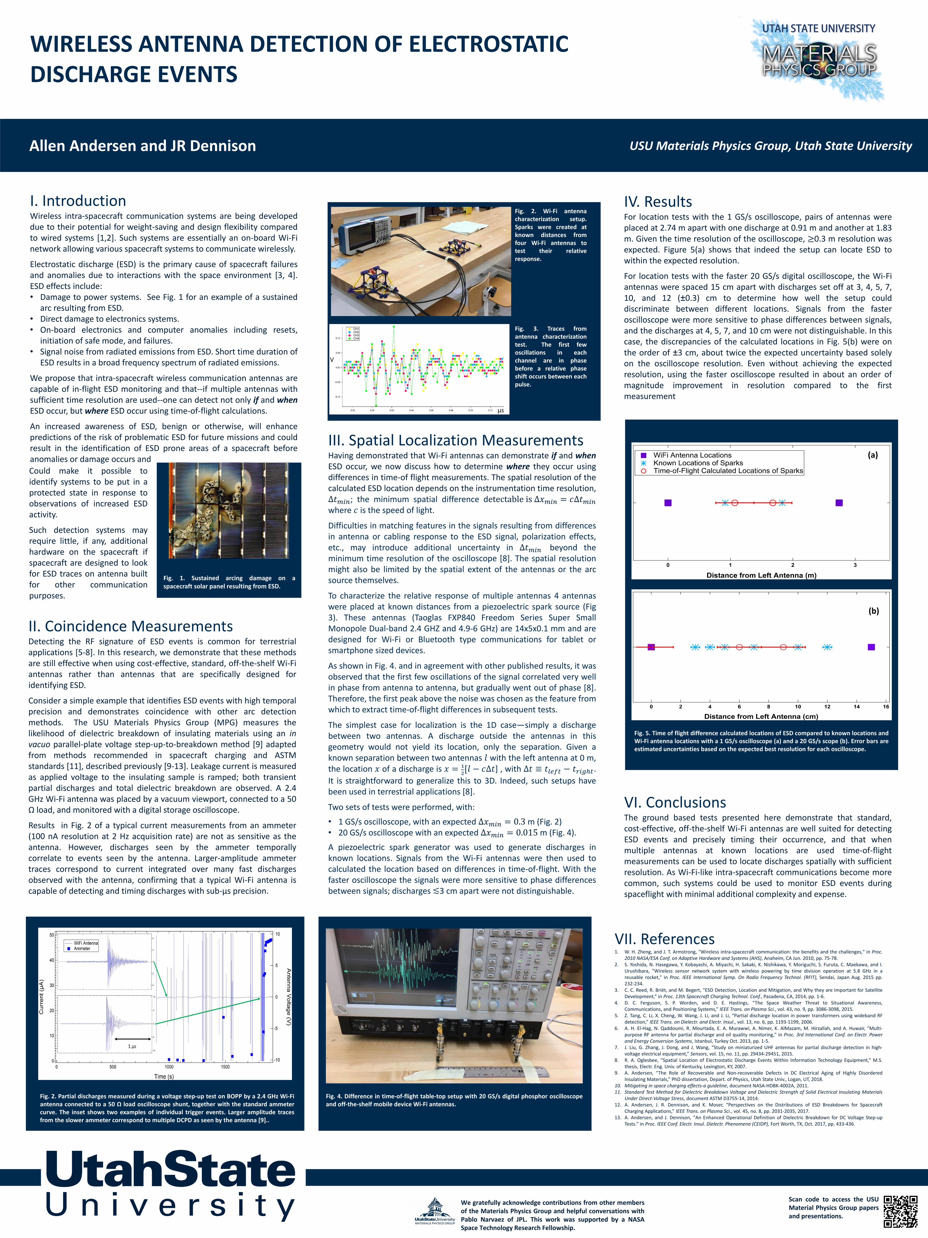
IV. ResultsFor location tests with the 1 GS/s oscilloscope, pairs of antennas wereplaced at 2.74 m apart with one discharge at 0.91 m and another at 1.83m. Given the time resolution of the oscilloscope, ≥0.3 m resolution wasexpected. Figure 5(a) shows that indeed the setup can locate ESD towithin the expected resolution.
For location tests with the faster 20 GS/s digital oscilloscope, the Wi-Fiantennas were spaced 15 cm apart with discharges set off at 3, 4, 5, 7,10, and 12 (±0.3) cm to determine how well the setup coulddiscriminate between different locations. Signals from the fasteroscilloscope were more sensitive to phase differences between signals,and the discharges at 4, 5, 7, and 10 cm were not distinguishable. In thiscase, the discrepancies of the calculated locations in Fig. 5(b) were onthe order of ±3 cm, about twice the expected uncertainty based solelyon the oscilloscope resolution. Even without achieving the expectedresolution, using the faster oscilloscope resulted in about an order ofmagnitude improvement in resolution compared to the firstmeasurement
Fig. 4. Difference in time-of-flight table-top setup with 20 GS/s digital phosphor oscilloscopeand off-the-shelf mobile device Wi-Fi antennas.
Could make it possible toidentify systems to be put in aprotected state in response toobservations of increased ESDactivity.
Such detection systems mayrequire little, if any, additionalhardware on the spacecraft ifspacecraft are designed to lookfor ESD traces on antenna builtfor other communicationpurposes.
Fig. 2. Partial discharges measured during a voltage step-up test on BOPP by a 2.4 GHz Wi-Fiantenna connected to a 50 Ω load oscilloscope shunt, together with the standard ammetercurve. The inset shows two examples of individual trigger events. Larger amplitude tracesfrom the slower ammeter correspond to multiple DCPD as seen by the antenna [9]..
µs
V
Fig. 3. Traces fromantenna characterizationtest. The first fewoscillations in eachchannel are in phasebefore a relative phaseshift occurs between eachpulse.
(a)
(b)
Fig. 5. Time of flight difference calculated locations of ESD compared to known locations andWi-Fi antenna locations with a 1 GS/s oscilloscope (a) and a 20 GS/s scope (b). Error bars areestimated uncertainties based on the expected best resolution for each oscilloscope.