wireless access in ultra-reliable low-latency ... · a perspective on the relationship between...
TRANSCRIPT

1
Wireless Access in Ultra-Reliable Low-LatencyCommunication (URLLC)
Invited Paper
Petar Popovski, Cedomir Stefanovic, Jimmy J. Nielsen, Elisabeth de Carvalho, Marko Angjelichinoski,Kasper F. Trillingsgaard, and Alexandru-Sabin Bana
Dept. of Electronic Systems, Aalborg University, 9220 Aalborg, DenmarkEmails: {petarp,cs,jjn,edc,maa,kft,asb}@es.aau.dk
Abstract—The future connectivity landscape and, notably, the5G wireless systems will feature Ultra-Reliable Low LatencyCommunication (URLLC). The coupling of high reliability andlow latency requirements in URLLC use cases makes the wirelessaccess design very challenging, in terms of both the protocoldesign and of the associated transmission techniques. This paperaims to provide a broad perspective on the fundamental tradeoffsin URLLC as well as the principles used in building accessprotocols. Two specific technologies are considered in the contextof URLLC: massive MIMO and multi-connectivity, also termedinterface diversity. The paper also touches upon the importantquestion of the proper statistical methodology for designing andassessing extremely high reliability levels.
Index Terms—Ultra-reliable communication, URLLC, IoT, 5G,access protocols, masssive MIMO, multi-connectivity.
I. INTRODUCTION
During the past three decades wireless connectivity hasbecome a commodity, assumed to be practically always presentand visible only when absent. This has naturally increasedthe confidence in wireless-enabled applications and services,leading to the idea of using wireless at a large scale tosupport mission-critical communication links. This trend hasbeen termed ultra-reliable communication (URC) [1], wherethe level of connectivity guarantees, e.g. > 99.999 % of thetime, matches the cable-based communication systems.
Ultra-reliability has inevitably become a part of theemerging 5G wireless systems. Indeed, 5G aims to coverthree generic connectivity types: enhanced Mobile Broadband(eMBB), massive Machine-Type Communication (mMTC)and Ultra-Reliable Low-Latency Communication (URLLC).As it can be seen from the name, ultra-reliability is entangledwith the requirement for low latency in the context of 5Gsystems. This makes URLLC very challenging, but also ratherrestrictive. In the earlier days of ultra-reliable wireless [1],there was a proposal to consider two types of ultra-reliableconnectivity: (i) URC over a long term, in which the requiredlatency is > 10 ms; (ii) URC in a short term, with latency of≤ 10 ms. URC over a long term is interesting for use casesin which one needs resilient wireless connections, such as indisaster scenarios or remote interactions with a larger latencybudget, e.g. changing a route of a drone. URC over short
term contains URLLC1 and is meant for applications with verystringent latency requirements, such as communication amongmachines and robots in Industry 4.0 use cases. However, whileURLLC has been established as a concept in the commu-nity, URC over long term has been only scarcely present.We will therefore keep the focus in the paper on URLLC,noting that the insights about ultra-reliable connections andthe communication-theoretic principles discussed here can beapplied to URC defined over both short and long term.
In this paper we will treat a set of fundamental problemsin wireless access for URLLC. The objective is to providethe reader with a framework that can be used to analyze anddesign ultra-reliable wireless systems. Our previous article [2]can be seen as a predecessor of this work, where we haveoutlined the principles and the building blocks for wirelessaccess in URLLC. This paper is intended to provide an in-depth treatment of some of the aspects and techniques asso-ciated with URLLC. We provide a detailed discussion on thecommunication-theoretic principles that are underpinning thedesign of URLLC. Compared to [2], here we have a detaileddiscussion on medium access control (MAC) protocols, useof large number of antennas in massive MIMO for providinghigh reliability, as well as the concept of interface diversityand multi-connectivity. We are also addressing a fundamentalquestion, largely ignored in the literature so far: what are thestatistical requirements to measure and verify ultra-reliability.It should be noted that this paper does not include all thedetails relevant for the discussion on the transmission of shortpackets; this has been discussed to a sufficient level in [2]and [3].
The paper is organized as follows. The next section pro-vides an overview of the URLLC use cases that create thecontext for developing wireless access protocols, as well as therequirements associated with them. Section III elaborates onthe communication-theoretic principles of URLLC, providinga perspective on the relationship between latency, packet size,bandwidth, and finite-blocklength treatment. This is followedby Section IV on access networking, where a special emphasisis put on the problem of frame synchronization, a procedure
1URLLC is often associated with latencies of around 1 ms, such that 10 msin this context is too long.
arX
iv:1
810.
0693
8v1
[cs
.IT
] 1
6 O
ct 2
018

2
that needs to have very high reliability in order to supportpacket decoding in URLLC scenarios. Section V sheds lighton Massive MIMO, a technology that relies on extreme spatialdiversity, which makes it a natural candidate for supportingultra-reliable transmissions. Since the future URLLC devicesare likely to have multiple communication interfaces, Sec-tion VI is dedicated to ultra-reliability achieved through multi-connectivity, i.e. interface diversity. Section VII treats thefundamental questions related to the statistical aspects of ultra-reliability. Some references to the related work are scatteredthrough the text, while a comprehensive overview of the state-of-the-art in the URLLC literature is provided in Section VIII.The last section concludes the paper and provides a perspectiveon some open issues.
II. URLLC USE CASES AND REQUIREMENTS
URLLC brings a significant novelty to 5G as a system.Along with mMTC, it makes 5G qualitatively different fromthe previous mobile wireless generations. Ultra-reliable com-munication is potentially an enabler of a vast set of ap-plications, some yet unknown. To put this in perspective,wireless connectivity and embedded processing have signifi-cantly transformed many products by expanding functionalityand transcending the traditional product boundaries [4]. Forexample, a product stays connected to its manufacturer throughits lifetime for maintenance and update. Ultra-reliable wirelessbrings this transformation to the next level, as the availabilityof wireless connectivity practically all the time is an importantassumption that a system designer should account for whendesigning a system. For example, ultra-reliable wireless con-nectivity between two parts of a system removes the need fortheir physical attachment.
In general, the applications and the use cases of URLLCcan be divided into two groups: (i) cable replacement andits extensions and (ii) native URLLC applications. The onesrelated to cable replacement are transforming some of thecurrent applications that rely on cabled connections, but alsoadd a new quality due to the flexibility of wireless. An exampleof this are the digital systems in Industry 4.0, where wirelesswill replace cabled connections, but also give rise to newtypes of interactions, e.g. among cooperative robots. On theother hand, a native URLLC application is the one that hasno precedent in wired communication; an example is vehicle-to-vehicle (V2V) communication.
A comprehensive treatment of the URLLC use cases iscarried out in 3GPP standardization. At the moment of writingof this article, 3GPP is about to start standardization workon Release 16, which should address both the reliability andlatency in future mobile cellular networks, thus setting thestage for URLLC services. The general vision of URLLCrequirements by 3GPP is presented in [5]:• A reliability requirement of 1−105 (i.e. 99.999 %) with a
user-plane radio latency2 of 1 ms for a single transmissionof 32-byte long packet.
2Radio latency is measured from the moment of the reception of a packetby layer-2 radio protocol at the transmitting end to the moment of the deliveryof the packet to the layer-3 protocol at the receiving end.
• A user-plane average latency of 0.5 ms for both uplinkand downlink, without an associated reliability value.
However, these figures are by far insufficient to describe thevariety of use cases and the associated requirements of theverticals that 5G is envisioned to support, as discussed next.Furthermore, as discussed in Section VII, these specificationsare also insufficient from a statistical viewpoint.
The automotive 5G URLLC cases represent an importantsegment of the ongoing 3GPP standardization and can be di-vided into assisted, co-operative and tele-operated driving [6],[7]. Their user plane reliability requirement is 1−105 with theassociated maximum end-to-end (E2E) latency requirement of5 ms for assisted, 10 ms for co-operative, and 20 ms for tele-operated driving, both in the uplink and downlink. Note that,as a rule of thumb, radio latency can be estimated as 1/10 ofE2E latency [6].
Another important set of URLLC use cases is related tomonitoring and control of industrial processes, belonging tothe emerging paradigm of Industry 4.0. The most importantexamples are motion control, factory automation and processautomation [6], [8]. Motion control pertains to real-timecontrol of machines with moving parts, and is characterized byuser-plane reliability of 1−10−5 with E2E latency of 1 ms (i.e.the user-plane radio latency of 0.1 ms). Moreover, this use caseis about isochronous transmission of sensory and actuationinformation in the upink and downlink, respectively, requiringuser-plane E2E jitter of 1 µs. Factory automation (also referredto as discrete automation or discrete manufacturing), accordingto 3GPP [8], requires user-plane reliability of 1 − 10−4 withuser-plane E2E latency of 10 ms and jitter of 100 µs. However,in some other sources, this use case is characterized with anextreme reliability requirement of 1− 10−9 or more [9]–[12],with a more demanding user-plane latency of 1 ms (for localmonitoring and control setups) and 5 ms for (remote setups)and jitter of 1 µs [10]. Process automation, which is relatedto production of goods in bulk quantities, requires user-planereliability of 1− 10−6 and E2E latency of 50 ms and jitter of20 ms, according to 3GPP [8]. Again, industrial sources aimat more stringent values that match the ones for the factoryautomation [9], [10].
We also mention the category of URLLC use cases thatbelong to the tactile Internet; their common feature is theexistence of haptic feedback which puts the most stringentrequirements in terms of reliability and latency. As an example,the haptic feedback in tele-surgery may require reliability of1− 10−9 and round-trip time as low as 1 ms [11].
The novelty of 5G is that reliability and latency are alsoexplicitly involved in mMTC use cases, e.g. in monitoring ofnon-time critical process and logistics in the contexts of smartcities and factories [6], where user-plane reliability is set to95 % with a maximum radio latency of 0.5 ms. Moreover,enhanced Mobile BroadBand (eMBB) service category alsofeatures general requirements of user-plane radio latency of4 ms, both in the uplink and downlink [5]. These latencyfigures are lower than what 4G is able to provide, where thetarget user-plane radio latency is 10 ms [13]. We also notethat reliability, as defined in 5G standardization, does not existas a requirement in 4G. In summary, low latency and high

3
reliability seem to be intrinsic to 5G, no matter the actual usecase and service category.
Finally, we note that in this section we have focused only onthe latency and reliability as the key performance parameters.More information about other performance parameters, suchas availability, experienced data rates, payload sizes, as wellas about deployment setups, security and other features, canbe found in the references mentioned in the section.
III. COMMUNICATION-THEORETIC PRINCIPLES OFURLLC
The objective of this section is to introduce communication-theoretic considerations on the modeling and the fundamentaltradeoffs in URLLC.
A. Communication-Theoretic Model
We will build our discussion of design principles andanalysis based on the following baseband model of a receivedsignal y
y = hαx+ z + w (1)
as well as its generalizations. Here h is the channel coefficient,which in the general MIMO case is a matrix of channelcoefficients; α is the activity indicator; x is the transmittedsignal; z is the noise; and w is the interference. The activityindicator value is α = 1 if there is an actual transmissionx and is α = 0 otherwise. All variables h, α, x, z, w arerandom and contain uncertainty; however, the receiver wishesto learn only α and, if α = 1, decode x. The knowledge aboutthe other three variables h,w, z can be partial, statistical, oreven non-existing. Let us take an initial look into the natureof these random variables; we will treat h, α and x in detailsthroughout the paper.
The most common random disturbance in communicationsystems is the noise z. The statistics of the noise is usuallyknown and in the most common case is Gaussian, with aknown noise power. Some of the most fundamental resultsin information theory, both in asymptotic case and in the caseof packets with finite blocklength, are related to the Gaussianchannel with known noise variance.
The situation is substantially different when the interferenceterm w is considered. The knowledge about w depends onthe part of the radio spectrum in which the bandwidth B isallocated. In a spectrum that has a certain type of license, thelicense-owner pays in order to acquire the right to managethe interference in that spectrum. This does not mean thatthe interference is non-existent, but is turned into a knownunknown and the spectrum owner can control or at leastinfluence the interference and its statistics.
On the other hand, if the spectrum is unlicensed, thenthe statistics of w is largely unknown. Indeed, the openaccess to the unlicensed spectrum puts constraints on theway a given transmitter may operate, but does not limit thenumber of independently owned systems that can run in closeproximity of each other3. The interference in unlicensed, but
3In other words, one can buy and turn on an arbitrary number of WiFiaccess points in a small space, e.g. room and set them up to transmit atdifferent channels, thereby occupying the whole unlicensed spectrum.
also sometimes in licensed bands, can be regarded as the mostsignificant “unknown unknown” in the system model and oneshould used risk-based methods [14] to assess its impact forURLLC communication. This is elaborated in Section VII.
The knowledge of the channel h or at least its statisticsis critical in URLLC systems. Even if we consider a non-coherent communication, where the receiver does not need toknow or to learn h, the precise knowledge of the statisticsof h is crucial to be able to guarantee a certain reliability ofcommunication.
Finally, finding out x is the central task of each receiverand we will treat it throughout the whole paper. The level ofknowledge about the activity of the transmitter α depends onthe communication scenario. In a downlink transmission, theBS is the only transmitting candidate (except in a discoveryprocess) and the receiving device expects to receive the signal,such that for this case we can take α = 1. However, foruplink transmission, in general, the BS does not a priori knowwhether the user is active, which translates into uncertaintyabout α. Finding out the values α for the devices connectedto the same BS is the access protocol problem, treated inSection IV, and it contributes substantially to the ultra-reliableperformance.
In the rest of the paper, we will treat in details varioustechniques and aspects of URLLC in the light of the modelgiven by (1).
B. Relating Latency and ReliabilityLatency can be defined in different ways and at different
layers of the communication protocols. The simplest definitionof a latency, treated in this paper, is the delay that a data packetexperiences from the ingress of a given protocol layer at thetransmitter to the egress of the same layer at the receiver. Inapplications related to, e.g. remote controls of robots or drones,one is interested in a two-way or round-trip delay.
Under the constraints of a URLLC service, the definitionof reliability should be coupled to the latency requirement.In fact, one can say that, when the latency requirement isabsent (theoretically infinite), then transmitting at a rate thatis lower than channel capacity offers perfect reliability. Fromthe perspective of an application, with a predefined latencyconstraint, we can define the reliability of a communicationsetup as the probability that the latency does not exceed thisdeadline, and outage as the probability that it does. Fig. 1shows the generic requirement in terms of latency and reliabil-ity, applicable not only to point-to-point link, but also arbitrarycommunication setup. The exact numbers on the deadline andthe reliability are dependent on the application. We note thatthe latency cumulative distribution function (CDF) asymptoteis equal to 1 − Pe, where Pe is the probability of residualpacket loss or packet error. This residual packet loss reflectsthe fact that some packets will never be delivered due to, forexample, limits on the number of retransmissions in link-layerprotocols, buffer overflows, synchronization failures, etc.
C. The Fundamental Tradeoffs and Packet StructureAs URLLC is often associated with transmission of controls
and commands over wireless link in a distributed system, one

4
1
x
Pr{latency x}Pe
deadline
reliability
outage
Fig. 1. Relation between outage, reliability, latency, and deadline.
of the basic assumptions about URLLC is that they involvesmall payloads. This naturally creates the association withthe transmission of short packets [3] and the use of finite-blocklength information theory. It is instructive to look at thebasic choices and tradeoffs that decide the packet length in anURLLC setting.
Instead of talking about the payload size and latency, weconsider a set of five variables: bandwidth, rate, reliability,energy, and latency. Let us at first fix the latency to T . Giventhe payload size of D bits and the maximal latency T , wecan determine the minimal transmission rate Rbps in [bps].Note that in the standard information-theoretic models, thedata rate is expressed in terms of bits per channel uses [bpcu],here denoted simply by R. By selecting the bandwidth B, thenumber of channel uses available for transmission is 2BT ,such that the different types of data rates are related as follows:
R =D
2BT=Rbps
2B[bpcu] (2)
The next variable is the energy. This may refer to the totalenergy consumed during the transmission by the transmitterand the receiver. It can even be understood in a more generalway, encompassing anything that adds diversity and hardensthe received signal, such as the use of multiple antennas(however, without adding spatial channels for additional datamultiplexing). Let us fix the energy used for transmissionwithin the time T . The SINR at the receiver is determined bythis energy, along with the channel realization and the interfer-ence, which are variables that cannot be chosen. With all thesevariables fixed, one can determine the achievable reliabilityof the transmission, denoted by 1 − ε. In an analogous way,of other four variables are fixed, for example rate, reliability,energy and latency, then one can find what is the requiredbandwidth B.
These, rather basic, considerations, are very important to getclarity in describing the models for URLLC. This is illustratedby the following two URLLC aspects:(1) Given the latency T , the size of the packet blocklengthin terms of available channel uses, equal to N = 2BT , canbe regulated by selecting the bandwidth B. If the bandwidthavailable for transmission is very large, then the blocklengthbecomes very large as well. In other words, large bandwidthcan move the transmission regime towards asymptoticallylarge packet lengths; however, the data rate becomes very lowand so does the spectral efficiency.(2) Both the sender and the receiver use energy during thecommunication. Assume there is a single sender, Alice, and
preamble frame sync. end-device ID payload authentication frame
check seq.
4 bytes 2 bytes 4 bytes 0-12 bytes variable 2 bytes
Fig. 2. Example of a packet format used in a low-throughput IoT system.The structure is largerly inherited from the common packet structure used inbroadband systems.
two possible receivers, Bob and Carol. If Alice sends to Bob,but not to Carol, then the activity indicator for Bob, denotedby αB , see (1), is given by αB = 1. For Carol it shouldbe αC = 0. If this is not known in advance, e.g. throughpre-scheduling, then Bob and Carol should learn it fromAlice’s transmission, which requires spending some energy ondetection and decoding and carrying out a hypothesis testingabout the activity factors αB and αC . Alternatively, they canboth set always αB = αC = 1 and receive anything thatcomes from Alice. In this case, only after decoding the packet,Bob and Carol figure out who is the intended recipient ofthe packet. This can improve the reliability, since α does notneed to be decided separately, but it also increases the receiverenergy consumption, as a receiver decodes packets that are notnecessarily intended for him/her.
D. URLLC Packet Structure
As already mentioned, a general requirement for URLLCin 3GPP is reliability of 1 − 10−5 (i.e. probability of errorε = 10−5) with latency of T = 1 ms and for a transmissionof a packet of size D = 32 bytes. In addition to the data, thepacket should also contain signaling information/metadata.
Although not directly related to URLLC, a good exampleof a short packet format is depicted on Fig. 2, taken from lowthroughput networks [15]. It clearly illustrates that a significantportion of the packet is spent on metadata as well as resourcesfor performing auxiliary operations, such as synchronizationand packet detection. As discussed in [2], when the reliabilityrequirements are as high as in URLLC, one can no longerassume that the transmission of the metadata and the auxiliaryprocedures are perfectly reliable. Indeed, the probability ofsuccess for a given packet π with a structure as the one onFig. 2 is given by:
PS(π) = PS(A)PS(M)PS(D) (3)
where PS(A), PS(M), and PS(D) denote the success prob-ability of the auxiliary procedures, metadata and data, re-spectively. This illustrates the point that the packet designthat is based on separation of the resource for auxiliaryprocedures, metadata, and data leads to product of the successprobability of the different elements, thus deteriorating theoverall reliability.
Let us illustrate the impact of (3) for short packets. Forsimplicity, let us assume that PS(A) = 1, while the packet hasD = 16 bytes of data and M = 16 bytes of metadata. Thelatency is set to T = 1 ms, while the bandwidth B shouldbe determined such as to achieve the desired reliability of1−10−5. For the sake of argument, we assume that B is lowerthan the coherence bandwidth of the system, such that a single
5
6 6.5 7 7.5 8 8.5 9 9.5 10
0 [dB]
50
100
150
200
250
300
350
400
450B
[kH
z]
joint encodingseparate encoding
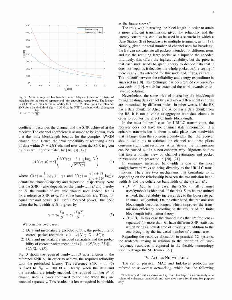
Fig. 3. Minimal required bandwidth to send 16 bytes of data and 16 bytes ofmetadata for the case of separate and joint encoding, respectively. The latencyis set to T = 1 ms and the reliability to 1− 10−5. Here γ0 is the referenceSNR for a bandwidth of B0 = 100 kHz; the SNR for a bandwidth B is given
by γB = γ0B0
B.
coefficient describes the channel and the SNR achieved at thereceiver. The channel coefficient is assumed to be known, suchthat the finite blocklength bounds for the complex AWGNchannel hold. Hence, the error probability of receiving b bitsof data within N = 2BT channel uses when the SNR is givenby γ is well approximated by [16] [3] [17]:
ε(N, γ, b) = Q
(NC(γ)− b+ 1
2 log2N√NV (γ)
)(4)
where C(γ) =1
2log2(1 + γ) and V (γ) =
γ(γ + 2)
2(γ + 1)2log2
2 e
denote the channel capacity and dispersion, respectively. Notethat the SNR γ also depends on the bandwidth B and therebyon N , the number of available channel uses. Indeed, let usfix a reference SNR to γ0 for some bandwidth B0. Then, forequal transmit power (i.e. useful received power), the SNRwhen the bandwidth is B is given by
γ = γ0B0
B= γ0
2B0T
N. (5)
We consider two cases:
1) Data and metadata are encoded jointly, the probability ofcorrect packet reception is (1− ε(N, γ,D +M));
2) Data and metadata are encoded separately and the proba-bility of correct packet reception is [1−ε(N/2, γ,M)][1−ε(N/2, γ,D)].
Fig. 3 shows the required bandwidth B as a function of thereference SNR γ0 in order to achieve the required reliabilitywith the prescribed latency. The reference SNR γ0 in (5)is fixed to B0 = 100 kHz. Clearly, when the data andthe metadata are jointly encoded, the required number N ofchannel uses is lower compared to the case when they areencoded separately. This results in a lower required bandwidth,
as the figure shows.4
The trick with increasing the blocklength in order to attaina more efficient transmission, given the reliability and thelatency constraints, can also be used in a scenario in which aBase Station (BS) broadcasts to multiple terminals, as in [18].Namely, given the total number of channel uses for broadcast,the BS can concatenate all packets intended for different usersand use the resulting large packet as a input to the encoder.Intuitively, this offers the highest reliability, but the price isthat each node needs to spend energy to decode data that itdoes not need, as it decodes the whole packet before seeing ifthere is any data intended for that node and, if yes, extract it.The tradeoff between the reliability and energy expenditure isanalyzed in [18]. This technique has been termed concatenate-and-code in [19], which has extended the work towards cross-layer scheduling.
Nevertheless, the same trick of increasing the blocklengthby aggregating data cannot be used when different data chunksare transmitted by different nodes. In other words, if the BShas a data chunk for Alice and Alice has a data chunk fromthe BS, it is not possible to aggregate both data chunks inorder to counter the effect of finite blocklength.
In the most “honest” case for URLLC transmission, thereceiver does not have the channel state information. If acoherent transmission is about to take place over bandwidththat is larger than the coherence bandwidth, then the receivershould use pilots to estimate the channel and these pilotsconsume significant resources. Alternatively, the transmissioncan be carried out in a non-coherent way. Rigorous studiesthat take a holistic view on channel estimation and packettransmission are presented in [20], [21].
In summary, increased bandwidth is one of the moststraightforward ways to bring diversity to the URLLC trans-missions. There are two mechanisms that contribute to it,depending on the relationship between the transmission band-width B and the coherence bandwidth of the system Bc.• B ≤ Bc: In this case, the SNR of all channel
uses/symbols is identical. If the data D to be transmittedis fixed, then reliability increases due to the lower rate perchannel use (symbol). On the other hand, the transmissionblocklength becomes longer, which improves the trans-mission efficiency according to the results of the finiteblocklength information theory.
• B > Bc: In this case the channel uses that are frequency-separated for more than Bc have different SNR statistics,which brings a new degree of diversity, in addition to theone brought by the increased number of channel uses.
Regarding the resource allocation in practical 5G systems,the tradeoffs arising in relation to the definition of time-frequency resources is captured in the flexible numerologyused to design the 5G frames [22].
IV. ACCESS NETWORKING
The set of physical, MAC and link-layer protocols arereferred to as access networking, which has the following
4The bandwidth values shown on Fig. 3 are too large for a commonly seenvalues of coherence bandwidth and here they serve for illustrative purposeonly.

6
tasks: (i) resolving the uncertainty in the user activity andinferring the value of α from (1); (ii) performing the auxiliaryprocedures, notably synchronization; (iii) decoding metadataand data; and (iv) interacting with the higher-layer protocols,where latency is ultimately measured and assessed. Its op-eration has to be designed according to the target reliability-latency requirements and to the traffic patterns of the supportedservices. In this section we consider several generic accessnetworking options for URLLC services.
A. Access Networking for URLLC Services with DeterministicTraffic Arrivals
URLLC services with deterministic traffic arrivals pertainto closed-loop control applications that involve deterministicsensing-actuation cycles with rather short periods and extremelatency-reliability requirements. The examples of such ser-vices, which in essence demand isochronous communications,are motion control and factory automation.
For deterministic traffic arrivals, the value of α in (1) isknown a priori. A sensible access networking approach inthis case is to employ periodic, pre-configured reservation ofresources for data transmissions in both uplink and downlink,providing a deterministic timing of the traffic exchanges. Thisstatic allocation of the resources could be done offline, or usingsignaling exchanges that take place before the execution of theservice starts.
The operation of access networking with static allocationof resources relies critically on precise time synchronization5
among all involved network elements, which could be achievedusing an external synchronization network, such as GPS. Ifsuch solution is not viable, due to, e.g. cost or indoor/obscureddevice location, one could employ synchronization methodsthat are reliant on dedicated signaling exchanges among thenetwork elements. Nevertheless, achieving and maintainingsuch high level of synchronism in this way is a challengingtask, particularly if the jitter requirements of the service arestringent, which typically is the case, see Section II.
The error probability of a packet exchange between a deviceand the Base Station (BS) in case of static allocation is givenby
εdet = 1− (1− εsync)(1− εD)(1− εA) (6)
where εsync is the synchronization error, and εD and εA arethe probabilities that the data and the acknowledgement arenot successfully decoded, respectively, which depend only onthe choice of transmission parameters. Obviously, the usedsynchronization and the transmission methods have to ensurethat ε < εtarget, where εtarget is the target error-probability ofan acknowledged packet exchange.
B. Access Networking for URLLC Services with StochasticTraffic Arrivals
In case of services with stochastic traffic arrivals, the valueof α is not known a priori, and it is reasonable to consideroptions alternative to static allocation of the resources.
5Time synchronization relates to the distribution of absolute time refer-ences [23].
1) Four-step access: A four-step access procedure consistsof the following steps:
1) The device sends a transmission request. The probabilityof error at the BS for this message is εR.
2) The device waits to receive access grant denoting thereserved resources, error probability εG.
3) The device sends data in the uplink. Its error probabilityis εD.
4) The devices waits to receive an ACK, whose error prob-ability is εA.
The overall probability of error for stochastic arrivals in afour-step procedure is
εsto4 = 1− (1− εsync)(1− εR)(1− εG)(1− εD)(1− εA). (7)
In contrast to (6), the term εsync here refers to the initialsynchronization and not the absolute time synchronization, asthe latter is typically not required for URLLC services withstochastic arrivals due to their less stringent requirements.This initial synchronization is established through receptionof the synchronization information via downlink broadcastchannels. It contains carrier and frequency synchronizationthat will be exploited by the device for the subsequent uplinktransmissions.6
For a given target overall error probability εtarget, meeting therequirement εsto4 ≤ εtarget is more difficult than meeting εdet ≤εtarget, as (7) contains contribution from more steps than (6).However, four-step access makes sense if Pr[α = 1] � 1,as it aims to support only the active devices and thus offersan overall better use of resources then the one with the staticallocation.
The error probabilities in four-step access εi, i ∈{R,G,D,A} depend on the choice of the transmission param-eters, but also on some other aspects of the access procedureoperation. Specifically, transmission requests are typicallysent using a contention procedure among active devices; animportant example of such access networking can be foundin LTE. In this case, sending of a request is subject to theinterference w that includes the request of its contenders.Thus, special provisions should be made to keep the valueof εR low. A potential approach is to increase the numberof resources for contention, and thus statistically decreasethe interference generated by the other contenders. However,the standard contention algorithms, like slotted ALOHA, arerather resource-inefficient, especially if target collision prob-abilities are low. This calls for the application of contentionprocedures that are better suited to deal with interference, e.g.through use of successive interference cancellation [24], multi-packet reception [25], [26], etc.
Another approach to keep εR low is to statically allocatethe resources for sending the transmission request, no matterwhether the user is active (α = 1) or not (α = 0). Thisapproach is similar to the one considered in Section IV-B,also suffering from inflexibility. However, if the amount of
6One could thus argue that the four-step procedure actually involves fivesteps, where the first step is the one related to successful reception of downlinkbroadcast information. We also note that similar considerations apply to therest of the considered access procedures.

7
resources required to send a request is much smaller than theamount of resources required for the data transmission, thisapproach may attain the desirable efficiency.
Note that the successful reception of the request enables theBS to estimate the timing offset of the device and consequentlyinstruct the device via grant message to compensate this offsetin its subsequent data transmission. In other words, the esti-mation of the timing offset and its subsequent compensationeffectively play the role of frame synchronization. In thisrespect, access requests typically include metadata that fostersestimation of the timing offset.7
The probability of not receiving an access grant, εG, de-pends on the fact whether BS has sufficient data resources togrant to all requests, as well as the correct reception of theaccess grant packet. This kind of error can be influenced bythe scheduling and resource allocation policy to other usersand services.
For the sake of completeness, we note that the accessprocedures for the initial connection establishment in mobilecellular standards actually involve more than 4 steps beforethe data transmission can take place. For instance, in LTEconnection-establishment [27], a device that wants to establisha connection and send data has first to successfully send aseries of uplink messages with metadata8 used for timing-offset estimation, device’s identification and notification ofthe reason for connection establishment, security contextestablishment, etc. If a device is only sporadically active,the connections it establishes will become released. Thisimplies that sporadically active devices will have to undergothe connection-establishment procedure each time they haveto send data. Obviously, this represents a huge challengefrom both latency and reliability perspectives, a topic thathas attracted a lot of attention in the recent literature onefficient support of machine-type communications in cellularaccess [28].
2) Three-step access: In the three-step access, sending ofa request is skipped and the BS sends directly the accessgrant to poll the device. In this case, the value of the activityindicator α becomes set to 1, no matter whether the devicehas experienced a new packet arrival or not. This mode ofoperation makes sense for services in which the devices arepolled when their data becomes needed, or in which the BScan accurately predict when the device wants to send data,i.e, predict when α has changed from 0 to 1. Note thatan inaccurate prediction results in either resource waste, asresources are allocated when no URLLC message is pending,or an outage, when the resources are not allocated and themessage expires until the next transmission opportunity.
The overall probability of error the three-step procedure is:
εsto3 = 1− (1− εsync)(1− εG)(1− εD)(1− εA). (8)
In contrast to the four-step access and due to the lack ofthe timing offset estimation, a correct reception of the datatransmission in the three-step access is more challenging.
7In LTE access networking, this metadata is an Zadoff-Chu sequence;Zadoff-Chu sequences feature favorable auto- and cross-correlation properties.
8Specifically, ten messages with metadata [28].
!"#$%&#$'($%)&'*(&('"'
! " # )+,-!.)
,'%/$%
# )+,-!.)*!0)$ *!0)$
).!"
$ )+,-!.)
1'2/$"
! )+,-!.)
2!%%$2" )"'%"
1!)0"0!*& %&).0(0*3&40*(!4
Fig. 4. Frame synchronization: the receiver should detect the correct valueof µ.
Specifically, the BS has to detect where is the start of thedata transmission in the dedicated resources, i.e., to acquireframe synchronization directly on the data transmission itself.We turn to this problem in more details in Section IV-C.
3) Grant-free access: The 3-step procedure can be furtherdecreased to a 2-step procedure, termed grant-free access,where the transmission of the grant by the BS is skipped. Thefirst transmission is carried out by the device and it containsthe actual data that should be sent during the access procedure.The probability of error in this case is:
εsto2 = 1− (1− εsync)(1− εD)(1− εA). (9)
Although similar in form, the semantic difference between(9) and (6) is substantial. In case of grant-free access, thedata transmission is by default contention-based and subject topotential interference from data transmissions of other devices.The modest performance of the standard contention algorithmsnecessitates consideration of more advanced solutions thatare able to deal with interference, see [24]–[26]. Moreover,similarly to the three-step access, the BS has to acquire framesynchronization. Nevertheless, there are at least two reasonsto use grant-free access: (1) it decreases latency and (2) if theURLLC packets are very short, then the overhead brought bythe request/grant is very significant and impacts the systemefficiency.
We also remark that the assumptions for grant-free accesscan be further relaxed by not assuming prior synchronizationbetween the base station and the devices in its domain. Aprominent example of such approach is the pure ALOHA.However, when the reliability requirements are very stringent,this type of solutions is infeasible, in particular when theload/interference of the access is high.
C. Frame Synchronization
The task of the frame synchronization is to establish whereis the start of the received packet. This is a critical ingredientof all access procedures discussed above and in this sectionwe provide a brief discussion of the factors that affect itsreliability, as well as an illustration of the required resourcesto support very high reliability.
A common approach in frame synchronization is to placea marker, also known as synchronization sequence, at thebeginning of the packet, and the task of the receiver is todetect the marker in the observation made in the slot, seeFig. 4. An alternative approach is to employ blind framesynchronization, which exploits other forms of redundancy
8
contained in the packet, notably the knowledge of the channelcoding algorithm, in order to establish frame synchronization.However, this approach suffers from higher complexity.
For the marker-based approach, the optimal detection algo-rithm depends on the channel model [29], [30]. In high signal-to-noise-ratio regimes, the optimal detection algorithm can bewell approximated with the correlation between the locallygenerated marker and the subset of the received symbols thatare placed in the sliding window. The length of this window isequal to length of the marker and it slides symbol-by-symbolthrough the slot, see Fig. 4. Upon performing correlations forall window positions, the receiver selects the one with thehighest correlation value.
If the impact of noise can be neglected, then the receivermay miss the correct start of the frame if the marker happensto be generated in the rest of the packet by chance. Toillustrate this, let us consider a high SNR scenario, in whichBPSK modulation is used. Further, assume that the markerlength is Nm bits, the total packet length is Np bits, andthat the bit values of 0 and 1 in the rest of the packetare equiprobable, which is a reasonable assumption. Notethat this is different from the AWGN channel discussed inSection III-D, as here the input is set to be binary. The upperbound on the probability of correct frame synchronization canbe computed as
PUB =∑i
1
i+ 1Pr{C = i} (10)
where C is a random variable denoting the number of timesthat the marker is randomly reproduced by the packet symbols.In the expression for PUB we have neglected the impact of thenoise samples surrounding the packet, see Fig. 4. PUB can becomputed using the method presented in [31].
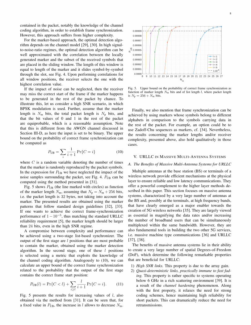
Fig. 5 shows PUB (the line marked with circles) as functionof the marker length Nm, assuming that Np = Nm + 256 bits,i.e. the packet length is 32 bytes, not taking into account themarker. The presented results are obtained using the markerpatterns that follow standard design guidelines [32], [33].If one wants to achieve the correct frame-synchronizationperformance of 1−10−5, thus matching the standard URLLCreliability requirement [5], the marker length should be largerthan 24 bits, even in the high SNR regime.
A compromise between complexity and performance canbe achieved using a two-stage list-based synchronizer. Theoutput of the first stage are l positions that are most probableto contain the marker, obtained using the marker detectionalgorithm. In the second stage, one of these l positionsis selected using a metric that exploits the knowledge ofthe channel coding algorithm. Analogously to (10), we cancalculate an upper bound of the correct frame synchronizationrelated to the probability that the output of the first stagecontains the correct frame start position:
PUB(l) = Pr{C < l}+∑i≥l
l
i+ 1Pr{C = i}. (11)
Fig. 5 presents the results for increasing values of l, alsoobtained via the method from [31]. It can be seen that, fora fixed value in PUB, the increase in l allows to decrease Nm.
8 9 10 11 12 13 14 15 16 17 18 19 20 21 22 23 24 25 26 27Nm
0.9999
0.99991
0.99992
0.99993
0.99994
0.99995
0.99996
0.99997
0.99998
0.99999
PU
B
l = 1l = 2l = 3l = 4l = 5
1-10-5
Fig. 5. Upper bound on the probability of correct frame synchronization asfunction of marker length Nm bits and of list length l, where packet lengthis Np = 256 +Nm bits.
Finally, we also mention that frame synchronization can beachieved by using markers whose symbols belong to differentalphabets in comparison to the symbols carrying data inthe rest of the packet. For example, an option could be touse Zadoff-Chu sequences as markers, cf. [34]. Nevertheless,the results concerning the marker lengths and/or receivercomplexity, presented above, also hold qualitatively in thosecases.
V. URLLC IN MASSIVE MULTI-ANTENNA SYSTEMS
A. The Benefits of Massive Multi-Antenna Systems for URLLC
Multiple antennas at the base station (BS) or terminals of awireless network provide efficient mechanisms at the physicallayer to ensure reliable and low latency communications. Theyoffer a powerful complement to the higher layer methods de-scribed in this paper. This section focuses on massive antennasystems, characterized by a very large number of antennas atthe BS and, possibly at the terminals, at high frequency bands,that have clearly emerged as a major enabler towards thecreation of 5G wireless networks [35]. They are largely viewedas essential in magnifying the data rates and/or increasingthe number of broadband users that can be simultaneouslymultiplexed within the same bandwidth. However, they arealso fundamental tools in building the two other 5G services,i.e. massive machine type communications [36] and URLLC[37], [38].
The benefits of massive antenna systems lie in their abilityto create a very large number of spatial Degrees-of-Freedom(DoF), which determine the following remarkable propertiesthat are beneficial for URLLC:
1) High SNR links. This property is due to the array gain.2) Quasi-deterministic links, practically immune to fast fad-
ing. This property is rather specific to systems operatingbelow 6 GHz in a rich scattering environment [39]. It isa result of the channel hardening phenomenon. Alongwith the first property, it relaxes the need for strongcoding schemes, hence maintaining high reliability forshort packets. This can dramatically reduce the need forretransmissions.

9
Fig. 6. Factory scenario where a massive MIMO access points serves multipleterminals (workstations).
3) High capability for spatial division multiplexing. In amulti-user system, this property can be exploited toimprove the latency incurred due to multiple access, asmultiple users can exchange data simultaneously. How-ever, it should be noted that the multi-antenna processingemployed to separate the users might induce additionalcomputational delay [40].
This section is dedicated to the exploitation of multipleantennas at the transmitter and receiver to support URLLC.At first, we need to establish the fact that the acquisition ofthe instantaneous CSI is one of the most severe limitationswith respect to URLLC when exploiting multiple antennas;see Section VIII. This is because the CSI acquisition is amajor protocol step in massive MIMO, impacting both thereliability and the latency. Taking this into account, we devisebeamforming methods that rely mostly on the structure of thechannel, that is, the direction of the propagation path. Theinformation about small scale fading is exploited as little aspossible. As the structure of the channel varies on a large scalebasis, its acquisition is more robust to device mobility.
It should be noted that the basic idea of using the singularvectors of the channel [41] or the structure of the channel [42],[43] (singular vector of the covariance matrix or steeringvectors) to build multi-user transceivers is not new. Here weshow that this basic idea creates a good basis to build URLLCtransmission schemes.
B. Channel Structure
To illustrate the main concepts of this section, we assume afactory-type environment as pictured in Fig. 6. An access pointis equipped with an array that consists of a very large numberof antennas while the terminals (workstations) are equippedwith one or possible small number of antennas.
Furthermore, we consider the simplified case of two termi-nals, each receiving a single stream of data from the accesspoint. The results can be easily extended to the general case.We adopt a cluster-based channel model where each clusteris characterized by a group of localized propagation paths
defined by their direction of departure and their direction ofarrival. Each propagation path is affected independently byan attenuation factor that follows a certain distribution. Thechannel from the access point to terminal k is described asthe sum of the propagation paths over all the clusters (in thesum, we make no distinction between clusters):
H(k) =
N(k)P∑i=1
α(k)i s
(k)i,rxs
(k)Hi,tx . (12)
N(k)P is the total number of paths. s
(k)i,tx and s
(k)i,rx are the
normalized steering vectors which characterize respectivelythe direction of departure from the BS and direction of arrivalto the terminal. When a terminal is equipped with a singleantenna, we have s
(k)i,tx = 1. The direction of the propagation
paths correspond to long-term statistics, meaning that for alocalized movement of the terminal the directions remainunchanged, whereas the coefficients {α(k)
i } corresponds tosmall scale fading and vary for small movements.
C. Covariance-based Design
In order to promote reliability and low latency, the generalpurpose of the beamforming design is to rely as much aspossible on the structure of the channel (i.e. the propagationpath) and as less as possible on the small scale fading proper-ties, while still benefiting from the properties brought by themassive number of antennas. This, in general, is a non-trivialtask as those properties are brought by coherent combining ofthe signals from each antenna, while this combining dependon the small-scale fading.
We adopt a design based on the covariance matrix of thesignal of each terminal at the transmitter and receiver. Thosecovariance matrices reflect the structural properties of thechannel.
The singular value decomposition of the covariance matrixat the transmitter for terminal k is:
R(k)tx = V(k)Λ(k)V(k)H . (13)
The columns of V(k) comprise the singular vectors denotedas v
(k)i and Λ(k) is a diagonal matrix grouping the non zero
singular values. Likewise, we write the covariance matrix atterminal k as:
R(k)rx = U(k)Λ(k)U(k)H . (14)
The singular vectors of R(k)rx are denoted as u(k)
i . The singularvectors associated to the maximal singular value R
(k)tx and
R(k)rx are v
(k)max and u
(k)max.
D. Transceiver Structures
We now examine zero-forcing beamforming designs. Theyare based on the following principles:
1) Inter-terminal properties: The inter-terminal interfer-ence can be removed based solely on the singular vectors ofthe covariance matrix of the interfering terminals defining theirsignal subspace. Interference is eliminated by projecting thetransmitted signal into the space orthogonal to signal subspace

10
of the interferers. This is advantageous in URLLC as thisoperation does not depend on instantaneous CSI.
2) Intra-terminal properties: Once the inter-terminal in-terference is removed, transmission to a single terminal mightexploit several levels of CSI knowledge at the transmitter.
A general form of the zero-forcing precoder for terminal 1is as:
F(1)ZF = P⊥V(2)︸ ︷︷ ︸
Term 1
V(1)︸︷︷︸
Term 2
w︸︷︷︸Term 3
(15)
Term 1. The first term forces the precoded signal to lie in thesignal subspace orthogonal to terminal 2. V(2) contains thesingular vectors of the covariance matrix at the transmitter forterminal 2 associated to non-zero singular values.Term 2. The columns of the matrix in the second termdefines the subspace of the transmit covariance matrix ofterminal 1 where the signal of interest lies. V(1) contains thesingular vectors of the covariance matrix associated to non-zero singular values.Term 3. Vector w defines a linear combination of the columnsof V(1). In general, this is a coherent operation requiring theknowledge of the channel projection onto the columns of V(1).
Note that term 1 and term 2 depend only on the long termstatistics of the channel.
E. Beamforming Methods
We test the following transceiver structures that are classi-fied by decreasing level of instantaneous CSI they exploit:• Interference free: as a performance upper bound, we plot
the case where the inter-terminal interference is ignored.• All SV - Coh: transceiver according to equation (15)
where all effective SVs are considered and coherent com-bining is performed. Information about the instantaneousCSI is needed.
• Strongest SV - Inst: transceiver according to equation(15) with V(2) = U(2) and V (1)
= v(1)I,max. This strategy
necessitates partial instantaneous CSI at the transmitter.Assuming that the receiver applies u
(1)max, the transmitter
estimates the projection of H(1) into the singular vectorsV
(1) and selects the strongest one, denoted as v(1)I,max.
• All SV - NCoh: transceiver according to equation (15)where all SV are considered. Transmission across the sin-gular vectors is performed non-coherently. The transmitpower along singular vector v(1)
i is λ(1)i .• Strongest SV - Av: transceiver according to equation (15)
with V(2) = U(2) and V(1)
= v(1)max.
For the methods relying on the whole set of singular vectors(”All SV”), the receiver estimates the aggregate channel matrixH(1)F
(1)ZF and matched filtering is applied. For the other
methods, the receiver applies the filter matched to v(1)max and
only requires the estimation of the projection of the aggregatechannel on v
(1)max.
F. Numerical Evaluations
Fig. 7 and Fig. 8 display the post-processing SINR and thePacket Error Rate (PER) associated to the different transceiver
Fig. 7. SINR in a 2-user scenario vs number of antennas at the terminals,ρ = 0dB.
structures. The total number of antennas at the access pointis M = 100 and the SNR is defined as ρ = P/σ2
n whereP is the total transmit power and σ2
n is the variance of thenoise at each receiving antenna. We normalize FZF in (15)so that the transmit power is divided equally among the users.The multipaths in a single cluster are assigned different delayswith an exponential decay that is up to 20dB.
Fig. 7 shows the post-processing SINR as a function ofthe number of antennas at the terminal side. As expected, weobserve a gap between the methods exploiting full CSI andthe methods based on second-order statistics or partial CSI.There is little differentiation for the latter methods.
Fig. 8 displays the Packet Error Rate (PER) as a function ofthe transmission slot for the case of a single antenna per user.The bandwidth is normalized, such that the number of channeluses directly reflects the delay. The payload is composed of100 bits drawn from a BPSK modulation, hence we transmit1 bit per channel use. We assume that the duration of thetraining for the coherent transmission techniques is twice asmuch as for the methods based on partial and no instantaneousCSI. A transmission slot is defined as the duration to send apacket (payload and overhead) using coherent transmission.Within a transmission slot, two packets can be sent usingnon-coherent transmission. The case where the users aremultiplexed in space (solid lines) or in time (dotted lines) isshown.
For the selected simulation parameters, the following obser-vations can be highlighted:• The general tendency is that performance gets better with
an increased exploitation level about the channel at thetransmitter.
• There is a notable exception when the terminals areequipped with multiple antennas and receive diversity isexploited. In Fig. 8, for N = 4, the non-coherent strategy(”All SV - NCoh”) performs the best. Hence, from aBER perspective, it is preferable to transmit the signal ina non-coherent fashion along each singular vector. Thenon-coherent transmission is compensate for by a receive

11
Fig. 8. Packet error rate in a 2-user scenario vs transmission slot, ρ = 0dB.Users are spatially multiplexed (solid lines) and time multiplexed (dashedlines).
coherent processing by multiple antennas that allows theextraction of diversity.
• Depending on the level of CSI exploited at the transmitter,space multiplexing is not always favourable.
VI. MULTI-CONNECTIVITY AND INTERFACE DIVERSITY
The mobile devices today have multiple radio interfacesand it is likely that many of the future devices will havethat as well. This is also an indicator that the 5G radiointerfaces will be deployed along with other radio interfaces.From the perspective of URLLC, the existence of multipleinterfaces offers an additional degree of diversity that can beused to achieve the stringent latency-reliability requirements.This is commonly known as multi-connectivity [44], whilehere use the terms link diversity or interface diversity in orderto emphasize the diversity role played by the availability ofmultiple different communication interfaces.
The idea of using multiple links or interfaces simultaneouslyis fairly natural and it has already emergent in some settings.In the context of 3GPP systems, LTE has supported Multi-Connectivity through Carrier Aggregation (CA) and Dual
Dual Connectivity
Interface Diversity
UEEnd host
rl(1)
rc(1)
rc(2)
rf
rl(2)
UEEnd host
rcrf
rl(1)
rl(2)
Single Connectivity
UEEnd host
rcrfrl
Fig. 9. Dual Connectivity and Interface Diversity architectures.
Connectivity (DC) since rel. 10 and 12, respectively. However,in this case the objective is throughput enhancement. Recently,in Rel. 15, Packet Duplication was introduced by 3GPP toboost reliability [44]. The data packet is duplicated on PDCPand transmitted on independent channels, either from the sameeNB on different carriers via CA or from different eNBs usingDC.
Packet Duplication in Multi-Connectivity architectures areexcellent for mitigating losses due to fading and interferenceon individual links or temporary scarcity of air interfaceresources. Nevertheless, the reliability of the end-to-end con-nectivity relies on the correct functioning of an infrastructureand core network, often belonging to a single operator. Whileinfrastructure and core networks are based on redundant solu-tions, they are still subject to single Point-of-Failure (PoF), e.g.through equipment misconfiguration. This reliance on a singlenetwork infrastructure can be mitigated by providing diversitynot only at a link level, but also a a level of a comunicationinterface or a path, as illustrated in Fig. 9.
The concept of Interface Diversity (IFD) was studied in [45].Interface Diversity provides an independent path from theUE to the internet (cloud), by the use of a different wirelesstechnology and/or a different mobile network operator. That is,IFD can be obtained by equipping a device with, for example,LTE/5G and Wi-Fi interfaces, or LTE/5G interfaces with SIMcards from two physically independent mobile network opera-tors. The key benefit of IFD is that there is no dependency ona single point of failure in the access network part. However,IFD requires that source and destination devices are configuredto duplicate packets and handle multiple received copies,respectively. In comparison, dual connectivity is transparentto the source and destination devices, above the MAC layer.It should also be noted that Packet Duplication is the simplestinstance of IFD, in which packet replicas are sent over differentinterfaces; more advanced IFD solutions involve various types

12
of data segmentation and packet-level coding.
A. Reliability Model and Numerical Illustration
Assuming link/component reliabilities as indicated in thefigure, we can use a series/parallel systems analogy fromreliability engineering to express the end-to-end reliability ofthe architectures as:
Rsingle = rlrcrf (16)
RDC =
(1−
N∏i=1
(1− r(i)l )
)rcrf (17)
RIFD =
(1−
N∏i=1
(1− r(i)l r(i)c )
)rf, (18)
where Rsingle, RDC and RIFD are for for a single link, N -link Dual Connectivity (DC) and N -interfaces Interface Di-versity (IFD). r(i)l and r
(i)c refer to the reliability of the ith
link/interface or core network, respectively. A key assumptionfor eq. (18) is that the considered interfaces are uncorrelatedin the sense that failures are occurring independently. This canbe ensured in practice by using different mobile networks thatdo not share physical infrastructure.
Let us initially consider the two-link/interface instancessketched in Fig. 9. The assumed default parameters are givenin Table I.
LTE/5G Wi-Fi
rl 0.99 0.9rc 0.999 0.99rf 0.9999 0.9999
TABLE IASSUMED DEFAULT RELIABILITY PARAMETERS.
Fig. 10 shows the resulting end-to-end outage probabilitywhen subject to different cellular link outages. The resultsshow that IFD using two independent networks is alwayssuperior or equal in outage compared to DC. Specifically,when the cellular links are good, i.e. outage below 10−2, theoutage of IFD is for an order of magnitude better comparedto DC. Even the alternative configuration where a LTE/5Gis complemented by an inferior, but independent Wi-Fi con-nection, is outperforming DC for link outages below 10−2.Further, the plot reveals that DC is better than using a singlelink, unless when the link outage is very low, and the end-to-end outage is instead dominated by the core outage probability.In comparison, consider the plot in Fig. 11, where the mobilenetwork core is assumed to be more reliable. In that case,the difference between DC and IFD is almost negligible. Theadvantage compared to using just a single link is significant,especially for link outages between 10−3 and 10−2.
VII. STATISTICAL ASPECTS OF ULTRA-RELIABLEGUARANTEES
In this section we investigate fundamental statistical ques-tions related to ultra-reliability; namely, how can high reli-ability be assessed and measured. The ambitious reliability
10-6 10-5 10-4 10-3 10-2 10-1 100
Cellular link outage probability (rl)
10-4
10-3
10-2
10-1
100
E2E
outa
ge p
robabili
ty
Single LTE/5G link
DC (2x LTE/5G links)
IFD (2x LTE/5G interfaces)
IFD (LTE/5G + Wi-Fi)
Fig. 10. End-to-end outage probability for varying cellular link outage. Notethat the assumed Wi-Fi link reliability is rl2 = 0.9.
10-6 10-5 10-4 10-3 10-2 10-1 100
Cellular link outage probability (rl)
10-4
10-3
10-2
10-1
100
E2E
outa
ge p
robabili
ty
Single LTE/5G link
DC (2x LTE/5G links)
IFD (2x LTE/5G interfaces)
IFD (LTE/5G + Wi-Fi)
Fig. 11. End-to-end outage probability for varying cellular link outage withrc = 0.9999. Note that the assumed Wi-Fi link reliability is rl2 = 0.9.
figures in URLLC only make sense when they are related toa statistical model of the context/environment in which theURLLC system is deployed. However, the statistical model ofthe wireless context for URLLC is not known a priori andsets the stage of the methods of statistical machine learning,through which one can estimate the statistical properties of theenvironment and offer reliability guarantees.
Here we consider these questions in a simple setting:we investigate the impact of limited transmitter-side channelknowledge on the reliability performance of the communica-tion links. Specifically, we consider a one-way communicationlink where the transmitter sends a packet to a receiver atrate R over a narrowband wireless channel; the model of thereceived baseband signal at the transmitter is given by (1). Toisolate and study only the impact of channel uncertainty, inthis section we ignore the effect of noise and interference andconsider packet errors due to outage, defined by the followingevent:
R > log2(1 + P ), (19)
where P denotes the received power; from model (1) we havethat P = |h|2 where we have normalized the transmit power|x|2 to unity.
Throughout the section, we will assume that the true distri-

13
bution of the channel is circularly-symmetric h ∼ CN (0, σ2),implying that the received signal is dominated by scattereddiffuse components; hence, the received envelope
√P = |h|
follows Rayleigh distribution and the received power P fol-lows exponential distribution with scale parameter θ = 2σ2
denoting the average channel power. Under the above assump-tion, the outage probability at transmission rate R is given bythe cdf of the received power:
F (R) = 1− e− 2R−1θ . (20)
Thus, transmitting at a specific rate over a Rayleigh channelwith average power θ, yields a specific outage probability. Thegoal of ultra-reliable communication is to choose the maximumrate that meets a predetermined reliability criteria. However, asdiscussed in the following paragraphs, designing the reliabilitycriteria and finding the most favorable rate is strongly linkedto how much the transmitter knows about the channel.
A. Naıve rate selection under channel uncertainty
First, consider the benchmark case where the transmitterknows the channel perfectly; this implies that the transmitterknows the average channel power θ also perfectly. Undersuch circumstances, the transmitter can easily determine themaximum rate as a function of θ at which an outage probabilitylevel of ε can be guaranteed with certainty:
Rε(θ) = sup {R > 0 : Pr(R > log2(1 + P )) ≤ ε} (21)= log2(1− θ ln(1− ε)). (22)
Rε(θ) is also known as ε-outage capacity.Now, consider the situation in which the transmitter has
no knowledge of the average power θ. Instead, it collectsn independent and noiseless power measurements x1, . . . , xnvia training. Having acquired x1, . . . , xn, a simple but naıvesolution would be for the transmitter to compute the MaximumLikelihood (ML) estimate of θ by averaging x1, . . . , xn, i.e.
θml(xn) =
1
n
n∑i=1
xi, (23)
and plug the obtained estimate in (22) to determine the trans-mission rate R(x1, . . . , xn), which now becomes a randomvariable. According to (20), every R yields specific outageprobability; hence, the sequence of random variables Xn
induces a distribution over F and the transmitter can no longerguarantee that the outage probability under transmission rateR(Xn) will be equal of less than ε.
B. Probabilistic rate-selection framework: parametric channelmodels
The above discussion shows that when the transmitter haslimited knowledge of the channel, it can only guarantee thereliability probabilistically. Formally, this can be done bychoosing the most favorable, i.e. the largest rate-selectionfunction R(Xn) such that predetermined statistical reliabilityconstraint is satisfied. Depending on the specific formulationof the constraint, the channel knowledge status at the trans-mitter and the actual statistics of the channel, finding the most
favorable rate-selection function might be involved problem.In the rest of the section, we will limit our discussion to thefollowing somewhat heuristic but intuitive choice. Specifically,given specific realization xn of Xn, the transmitter uses thefollowing transmission rate:
R(xn) = Rεn
(θml(x
n)), (24)
for some εn > 0; our aim is to find εn for each n such thatR(xn) is maximized under predefined reliability constraint.The outage probability under transmission rate selected ac-cording to (24) is still a random variable; however, selecting εnaccording to specific reliability constraint effectively controlsthe amount of uncertainty in the outage probability. Note thatfor εn = ε we have the naıve solution. Finally, we expectthat the transmission rate is consistent, i.e. as n→∞, R(xn)converges to the ε-outage capacity.
Choosing the specific formulation of the statistical reliabilityconstraint can be done in many ways. Here, we will considertwo approaches, described next.
1) Average Reliability (AR): Consider the following con-straint:
supθ
Pr[R(Xn) > log2(1 + Y )] ≤ ε, (25)
where the averaging is performed w.r.t. the joint distribution ofY,Xn. By rewriting the above according to the rule for totalprobability, by first averaging over Y and then averaging overXn, we observe that (25) guarantees that the worst-case meanof the outage probability F (Xn) will remain below ε. Notethat this does not guarantee that for some specific realization ofXn the outage probability will not be larger than ε. Regardingpotential use-cases, constraint (25) is suitable for dynamicenvironments and can be used when one wishes to optimizethe rate of the system and provide reliability guarantees jointlyover the training and the transmission, prior to the actualtraining.
Using the Rayleigh-channel assumption and the rate-selection function (24) and after few elementary computations,we obtain the following:
supθ
Pr[R(Xn) > log2(1 + P )] = (26)
= 1−(
1− ln(1− εn)
n
)−n. (27)
The maximum value of εn, satisfying (25) is given by:
εn = 1− e−n((1−ε)−
1n−1
). (28)
Clearly, as n→∞, εn → ε.2) Probably Correct Reliability (PCR): We consider an-
other, more restrictive reliability constraint that effectivelycontrols the higher order moments of the outage probabilityvia the concept of meta-probability [46]; namely, we require:
supθ
Pr[Pr[R(Xn) > log2(1 + Y )|Xn] > ε] ≤ ξ. (29)
In other words, we limit the probability that the outageprobability given Xn is larger than ε. Intuitively, ξ is an upperlimit on the willingness of the system to tolerate outages largerthan ε. So, the probability of outage is guaranteed to be equal

14
100 101 102
n
0.99999955
0.9999996
0.99999965
0.9999997
0.99999975
0.9999998
0.99999985
0.9999999
0.99999995
1
λǫ(θ)
ǫ = 10−9
ǫ = 10−8
ǫ = 10−7
ǫ = 10−6
(a) Average reliability constraint
100 101 102 103
n
0
0.1
0.2
0.3
0.4
0.5
0.6
0.7
0.8
0.9
1
λǫ(θ)
ξ = 10−9
ξ = 10−7
ξ = 10−5
ξ = 10−3
(b) Probably correct reliability constraint
Fig. 12. Parametric rate-selection under Rayleigh channel fading with average power θ = 10.
or less than ε with probability larger than ξ; again note thatthis does not guarantee that for specific realization of Xn theoutage probability will not be larger than ε. This approach ismore suitable for static environments where channel training isdone infrequently. In such circumstances, the average channelpower estimate is used to set the rate for multiple, possiblymany future transmission cycles; obviously, the transmitterhere needs to be more conservative.
Using the Rayleigh-channel assumption and the rate-selection function (24), we obtain the following simple result:
supθ
Pr[Pr[R(Xn) > log2(1 + Y )|Xn] > ε] = (30)
= 1−γ(n, n log(1−ε)
log(1−εn)
)(n− 1)!
, (31)
with γ(·, ·) denoting the lower incomplete gamma function.By choosing εn satisfying
1−γ(n, n log(1−ε)
log(1−εn)
)(n− 1)!
≤ ξ, (32)
we obtain a rate-selection function that satisfies (30) for any θ.Note that in the specific study of Rayleigh channel, the choiceof rate using PCR approach does not depend on θ. This is aconvenient result, stating that in case of Rayleigh channel, thetransmitter only needs to ensure that the rate does not violatethe maximum allowed tolerance ξ; such rate will be valid forany ε.
3) Evaluation: We evaluate both approaches w.r.t. the ratiobetween the average achievable throughput using rate R(Xn)and the optimal throughput given that the distribution is known
λε(θ) =E[R(Xn)1R(Xn)≤log2(1+Y )
]Rε(θ)(1− ε)
. (33)
We evaluate the average throughput via Monte-Carlo simu-lation with K trials by simply averaging the rates R(xn)provided that R(xn) ≤ log2(1+y) for any pair of realizations
y, xn. We depict λε(θ) as a function of n for different ε andfor θ = 10 in Fig. 12. We see that λ < 1 in both approaches,i.e. limited channel knowledge reduces the transmission rate.We also observe that the rate-selection function is consistent,that is as n grows large λ → 1. This reduction is dramati-cally visible for the PCR constraint; this is also expected as(30) is significantly more restrictive than (25). Hence, usingmeta-probability, although providing stricter and more firmreliability guarantees, reduces the average rate significantly.Beside, the rate converges significantly slower to the respectiveε-outage capacity.
C. Alternative channel models
We note that the rate-selection function cannot be alwaysguaranteed to be consistent. Specifically, when relaying onparametric channel models, the rate is consistent only inthe case when the true channel distribution adheres to theadopted model as above, where we assumed that the truechannel envelope is Rayleigh distributed. However, if the truechannel differs even slightly from the assumed model (e.g.a small specular component is also present), the rate is notlonger consistent and both the AR and PCR constraints willbe violated, see [47] for in-depth discussions. This can beviewed as a general pitfall of parametric channel models; whilethey provide fast convergence, they are prone to significantbias which lead to inconsistent rate and severe reliabilityviolations. As an alternative, one can consider non-parametricchannel modeling approaches. They indeed are guaranteed togive consistent rates under very mild channel restrictions butthey require extensive training; in fact, the number of channelsamples necessary to obtain non-negative transmission rategrows as [47]
n ∼ 1
ε. (34)
Finally, [47] suggests to use power law approximations ofthe channel tail as third alternative as they provide “the best

15
of the two worlds”; even though they do not guarantee rateconsistency due to approximation error, they are significantlyless biased than poor parametric models and they requirereasonable training samples lengths.
VIII. RELATED WORK
The body of literature on URLLC has been rapidly growingduring the recent years. Here we make a brief account of theliterature related to the topics assessed in the paper, notingthat this account is by no means exhaustive.
From the standardization perspective, the requirements ofthe URLLC “usage scenario” are originally defined in 3GPPdocument [5].Automotive URLLC cases, i.e. their servicearchitectures and requirements, are elaborated in [7]. Sim-ilarly, specification [8] elaborates service architectures andrequirements for URLLC use cases belonging to Industry4.0 and intelligent transportation systems (ITS). Finally, arecent specification concerning 5G New Radio (NR) and RadioAccess Network description [48] proposes some methods forthe facilitation of URLLC services, elaborated later in thissection.
A detailed description of URLLC use cases that are ex-pected to play important roles in future 5G networks can befound in [6]; these include automotive, Industry 4.0, ITS andad-hoc disaster and emergency relief. Another take on emerg-ing mission-critical services in cellular networks, such as tele-surgery, ITS and industrial automation, is given in [11]. Liveaudio production, another potential URLLC use case, is de-scribed in [49]; notably, this use case emphasizes isochronouscommunication that is not supported by 4G and the articleelaborates the ways to achieve it in 5G networks. A commonfeature of all mentioned all URLLC use cases is that theyare described by a single combination of target reliability andlatency parameters. In contrast, [1] proposes a more generalURLLC service model with reliable-service composition, bywhich target reliability performance progressively increaseswith latency.
Another line of works deals with general treatment ofwireless URLLC communications. A survey of challenges andmethods related to support of low-latency wireless communi-cations is presented in [50]. An assessment of the sources ofdiversity and their exploitation to enable wireless URLLC net-working is given in [2]. The challenges of high-performancewireless communications for industrial control are in focusof [51]. The study the fundamental energy-latency tradeoffin URLLC systems employing incremental-redundancy hybridautomatic repeat request in a specific context of point-to-pointwireless connectivity is presented in [52].
Traditionally, channel models have been used to study av-erage or cell edge channel conditions. In the case of URLLC,where reliability requirements are in the order of 10−5−10−9,it is the extreme tail of the channel model distribution thatis important. In [53], the URLLC level behavior of commonwireless channel models is investigated. The authors findthat in many cases, a simple power law model with fittedparameters can sufficiently characterize the tail. In practicalsystems, where only limited channel knowledge is available
and thus the specific channel model is unknown, the model un-certainty will inevitably impact the overlying communicationprotocol. In [54], the most critical dimensions of uncertaintyare identified and their impact analyzed for two examples ofcooperative communication protocols. A different perspectiveis taken in [14], where, first, relevant metrics and key enablesof URLLC are discussed, where after mathematical tools fromdifferent scientific disciplines are proposed for evaluating theURLLC properties of different wireless communication systemapplications. While traditionally dependability metrics suchas availability and reliability are expressed as functions oftime, [55] proposes an evaluation framework for extendingsuch analyses in the space domain, specifically consideringultra-reliable heterogeneous and homogeneous cellular com-munication systems.
A vast number of papers discuss cellular access networkingfor URLLC services, we mention only a handful of them thatexplicitly deal with uplink communications. Some guidelineson design and optimization of LTE and 5G new-radio inter-faces related to numerology, robust transmission modes andconnection management for URLLC services are presentedin [44]; the overall conclusion is that the spectral efficiencyis reduced with respect to services without latency and/orreliability constraints. Along this lines, 3GPP document [48]specifies the use of appropriate numerology and transmissiondurations for uplink resource reservations for URLLC traffic,such that adequate subcarrier spacing and/or short-durationtransmission can be achieved. An overview of high-leveloptimization of radio-resource management for both uplinkand downlink using the tools of network calculus and effectivebandwidth is made in [56]. Finding a scheduling policy whenthat allows multiple users to meet a target reliable-latencyobjective is the topic of [57], where the dynamic programmingand knapsack-inspired approaches are used to find optimal andcomputationally-efficient suboptimal policies, respectively.
A number of works address advanced grant-free and grant-based access schemes for cellular access networks. The ben-efits of multi-user detection in radio-access uplink are pre-sented in [58]. A scheme that exploit multi-user detectionin combination with grant-free access with proactive sendingof packet replicas is proposed in [59]. A grant-free schemefor batch arrivals that exploits replicas and SIC-based re-ceiver and offers latency-reliability guarantees is introducedin [60]. Coordinated sharing of uplink resources in a grant-free manner, where the arrived users transmit packet replicasaccording to predefined activity patterns is proposed in [61];the performance of the scheme is analyzed for both MMSE-and SIC-based receivers. Comparison of grant-free schemeswith proactive and reactive sending of replicas is made in [62];under the assumptions of an ideal control channel, perfectchannel estimation, MMSE-interference rejection combiningreceiver, and target reliability of 1 − 10−5, it is shown thatlatency of grant-free schemes is generally lower than of thegrant-based ones, while the choice between proactive andreactive grant-free schemes should be based on the load ofthe access network. In regards to the grant-based, four-stepaccess, the work [63] proposes a control channel design thatincreases the reliability of signaling exchanges. Finally, for the

16
sake of completeness, we note that the 3GPP specification [48]in essence inherits the uplink access procedures from LTE, seeremarks about LTE connection establishment in Section IV-B1.Successfully connected device can be granted periodicallyoccurring resources, which may be an option for devices withpredictable activity; otherwise the reserved resources will notbe used efficiently. It should also be noted that 3GPP at thispoint does not specify grant-free schemes for mobile cellularaccess.
Multiple antenna systems appear as a natural enabler forURLLC as multiple antenna communications provide highSNR and diversity links as well as spatial multiplexing capa-bility. Those properties contribute to increasing the reliabilityor the latency or both. In spite of their obvious advantages,however, those mechanisms are still relatively unexplored. Astatistical characterization of multiple-input, single-output sys-tems under statistical delay constraints is investigated in [64],using the tools of stochastic network calculus. In [37], forthe uplink of a single user massive MIMO system with 64antennas at the base station, diverse multi-antenna schemesare tested: coherent and non-coherent transceivers, transceiversassuming that the channel is unknown at the transmitter andusing space-time codes, where the preference is given tonon-coherent transceivers. In [40], the accent is put on theprocessing delay caused by multiple antenna processing at abase station in a multi-user massive MIMO system. In [38], amulti-user massive MIMO system network is optimized undera probabilistic constraint on the queue size to satisfy URLLCrequirements.
One central question in multi-antenna system is the acquisi-tion of instantaneous CSI. It is one of the most severe limita-tions to achieve URLLC when exploiting multiple antennas ina mobile environment constrained by channel coherence timeas well as extreme latency requirements. The most criticalacquisition occurs at the antenna array when the CSI is usedfor transmission mode (CSIT). In frequency division duplex(FDD) systems, CSIT acquisition requires a feedback loopfrom the terminals inducing a significant latency as the numberof links to report is large. In a massive MIMO system below6 GHz where the terminals have a small number of anten-nas, this concerns the BS in downlink transmission. In timedivision duplex (TDD) systems, latency can still be reducedby exploiting channel reciprocity [65], but remains critical.In a mmWave system, with potentially many antennas at theterminal, the issue concerns both side of the communicationlinks.
Acquisition of the CSI at the receiver is usually perceivedas less critical than at the transmitter as the delay betweenchannel estimation and data detection is short. However,extreme cases of mobility at the user side might requirean alternative to coherent detection, especially if URLLC isthe target. Hence, non-coherent detection methods can be anasset in that case. A particularly simple method [66] thatgreatly benefits from the presence of a massive number ofantennas is based on energy detection at the uplink of amassive MIMO system. The principle is to send a singlestream of data, collect and aggregate the energy from allantennas. Detection is performed based on the average channel
energy across the antenna array, which tends to a deterministicquantity for localized movements of the user and is thereforemuch more robust to user mobility than coherent detection. Inaddition, an efficient constellation design has been proposedin [67] that is able to benefit from the advantages of coherentcommunications at low mobility while switching to energydetection to ensure reliable communications at high mobility.
It is well-known from reliability engineering that ultra-highreliability can be effectively achieved through the paralleluse of independent system components. In communicationsystems this translates to using multiple channels in parallelto achieve redundancy. 3GPP NR rel. 15 specifies use ofPacket Duplication for URLLC services, where two indepen-dent transmission paths, from two different BSs, are usedsimultaneously to increase reliability and lower latency. Due tothe involvement of multiple BSs, packet duplication requiresmodifications in the network architecture [68], [69]. PacketDuplication can be achieved both through Dual Connectivityand Carrier Aggregation, which are compared in [68]. In [70],an information theoretic study of the achievable gain of usingjoint decoding in a multi-connectivity setting over traditionalMSC and MRC schemes is presented. For these schemes, thediversity multiplexing tradeoff that allows to trade outage-off outage probability and system throughput, is investigated.While the latency is not explicitly quantified in this work, theuse of short packets and demonstrated reduction of outageprobability enables URLLC. Finally, field trial measurementsare used to demonstrate the practical performance. An exten-sion of multi-connectivity is to complement BS links withD2D links, whereby UEs function as relays. A mathematicalevaluation framework based on short block length regime forsuch D2D extended systems is proposed in [71] and whereDF and AF relay strategies are compared to traditional BS-oriented MC. While multi-connectivity is typically assumingLTE or 5G links in a 3GPP system, the authors in [72]propose network architecture for enabling multi-RAT multi-connectivity, thereby allowing for example Wi-Fi or LTE-LAAto be exploited for multi-connectivity. As shown in [45], acombination of several different types of communication linkscan be flexibly used so as to optimize for a service-specificlatency/reliability/bandwidth consumption tradeoff.
IX. DISCUSSION AND OUTLOOK
In this paper we have discussed the principles of wire-less access for Ultra-Reliable Low Latency Communication(URLLC). We have used a communication-theoretic frame-work to provide discussion on the fundamental tradeoffs. Thiswas followed by elaboration on the important elements inaccess protocols. Two specific technologies were consideredin the context of ultra-reliable communication, massive MIMOand multi-connectivity (interface diversity). We have alsotouched upon the important question about the proper statis-tical methodology for designing and assessing ultra-reliablecommunication.
In the final remarks, we turn towards the issue of couplinghigh reliability with low latency, as it is done in the contextof 5G. Relaxing the latency requirements towards a long

17
term, e. g. beyond 10 or 50 ms, opens the design space forsolutions that have good system level characteristics, such ascoexistence with the other 5G services, or exhibit a higherenergy efficiency. It should also be noted that the latencyrequirements on the wireless link can be reduced by adoptinga holistic system design. For example, requiring 1 ms from thewireless link, while allowing source compression proceduresthat introduce much larger delay, is certainly not the optimalapproach. Hence, one is tempted to define new researchproblems related to joint source-channel coding and protocoldesign that are suited to meet end-to-end latency and reliabilityrequirements.
ACKNOWLEDGMENT
The work has partly been supported by the EuropeanResearch Council (ERC Consolidator Grant nr. 648382 WIL-LOW), and partly by the Horizon 2020 project ONE5G (ICT-760809).
REFERENCES
[1] P. Popovski, “Ultra-reliable communication in 5G wireless systems,” in1st Int. Conf. on 5G for Ubiquitous Connectivity (5GU). IEEE, 2014,pp. 146–151.
[2] P. Popovski, J. J. Nielsen, C. Stefanovic, E. d. Carvalho, E. Strom, K. F.Trillingsgaard, A. Bana, D. M. Kim, R. Kotaba, J. Park, and R. B.Sorensen, “Wireless Access for Ultra-Reliable Low-Latency Communi-cation: Principles and Building Blocks,” IEEE Network, vol. 32, no. 2,pp. 16–23, Mar. 2018.
[3] G. Durisi, T. Koch, and P. Popovski, “Towards massive, ultra-reliable,and low-latency wireless communication with short packets,” Proc.IEEE, vol. 104, no. 9, pp. 1711 – 1726, sep 2016.
[4] M. E. Porter and J. E. Heppelmann, “How smart, connected products aretransforming competition,” Harvard Business Review, vol. 92, no. 11,pp. 64–88, 2014.
[5] 3GPP, “3gpp tr 38.913 v15.0.0: Study on scenarios and requirementsfor next generation access technologies; (release 15),” Tech. Rep., Jun.2018.
[6] E2E-aware Optimizations and advancements for Network Edge of 5GNew Radio (ONE5G), “Deliverable D2.1: Scenarios, KPIs, use casesand baseline system evaluation,” Tech. Rep., Nov. 2017, Accessed 25-August-2018. [Online]. Available: https://one5g.eu/wp-content/uploads/2017/12/ONE5G D2.1 finalversion.pdf
[7] 3GPP, “3gpp tr 22.886 v16.0.0: Study on enhancement of 3gpp supportfor 5g v2x services (release 16),” Tech. Rep., Jun. 2018.
[8] ——, “3gpp ts 22.261 v16.4.0: Service requirements for the 5g system;stage 1 (release 16),” Tech. Rep., Jun. 2018.
[9] Ericsson, “Manufacturing reengineered: robots, 5G andthe Industrial IoT,” Ericsson Business Review, vol. 4,2015, Accessed 02-October-2018. [Online]. Available: https://www.ericsson.com/assets/local/publications/ericsson-business-review/issue-4--2015/ebr-issue4-2015-industrial-iot.pdf
[10] Siemens, “5G communication networks: Vertical industry requirements,”Tech. Rep., 2016, Accessed 02-October-2018. [Online]. Available:http://www.virtuwind.eu/ docs/Siemens PositionPaper 5G 2016.pdf
[11] H. Chen, R. Abbas, P. Cheng, M. Shirvanimoghaddam, W. Hardjawana,W. Bao, Y. Li, and B. Vucetic, “Ultra-Reliable Low Latency CellularNetworks: Use Cases, Challenges and Approaches,” IEEE Commun.Mag., Sep. 2018.
[12] B. Holfeld, D. Wieruch, T. Wirth, L. Thiele, S. A. Ashraf, J. Huschke,I. Aktas, and J. Ansari, “Wireless Communication for Factory Automa-tion: an opportunity for LTE and 5G systems,” IEEE Commun. Mag.,vol. 54, no. 6, pp. 36–43, Jun. 2016.
[13] ITU-R, “REPORT ITU-R M.2134: Requirements related to technicalperformance for IMT-Advanced radio interface(s),” Tech. Rep., 2008,Accessed 06-October-2018. [Online]. Available: https://www.itu.int/pub/R-REP-M.2134
[14] M. Bennis, M. Debbah, and H. V. Poor, “Ultra-reliable and low-latencywireless communication: Tail, risk and scale,” Proc. IEEE, vol. 106,no. 10, pp. 1834 – 1853, Oct. 2018.
[15] ETSI, “Low Throughput Networks (LTN); Functional Archi-tecture,” in ETSI GS LTN 002 V1.1.1, 2014. [Online].Available: http://www.etsi.org/deliver/etsi gs/LTN/001 099/002/01.01.01 60/gs LTN002v010101p.pdf
[16] Y. Polyanskiy, H. V. Poor, and S. Verd, “Channel coding rate in thefinite blocklength regime,” IEEE Trans. Inf. Theory, vol. 56, no. 5, Apr.2010.
[17] A. Bana, K. F. Trillingsgaard, P. Popovski, and E. de Carvalho, “Shortpacket structure for ultra-reliable machine-type communication: Tradeoffbetween detection and decoding,” in 2018 IEEE Int. Conf. on Acoustics,Speech and Signal Processing (ICASSP), Apr. 2018, pp. 6608–6612.
[18] K. F. Trillingsgaard and P. Popovski, “Downlink transmission of shortpackets: Framing and control information revisited,” IEEE Trans. Com-mun., vol. 65, no. 5, pp. 2048–2061, 2017.
[19] D. Tuninetti, B. Smida, N. Devroye, and H. Seferoglu, “Scheduling onthe gaussian broadcast channel with hard deadlines,” in 2018 IEEE Int.Conf. on Commun. (ICC). IEEE, 2018, pp. 1–7.
[20] J. Ostman, G. Durisi, E. G. Strom, M. C. Coskun, and G. Liva,“Short packets over block-memoryless fading channels: Pilot-assistedor noncoherent transmission?” IEEE Trans. Commun., Oct. 2018.
[21] G. C. Ferrante, J. Ostman, G. Durisi, and K. Kittichokechai, “Pilot-assisted short-packet transmission over multiantenna fading channels: A5g case study,” in 2018 52nd Annu. Conf. on Inf. Sci. and Syst. (CISS).IEEE, 2018, pp. 1–6.
[22] G. Berardinelli, K. Pedersen, F. Frederiksen, and P. Mogensen, “On thedesign of a radio numerology for 5g wide area,” in Proc. 11th Int. Conf.Wireless Mobile Commun.(ICWMC), 2015, pp. 13–18.
[23] “ITU-T Recommendation G.8260,” Accessed 17-August-2018. [Online].Available: https://www.itu.int/rec/T-REC-G.8260-201508-I/
[24] E. Paolini, C. Stefanovic, G. Liva, and P. Popovski, “Coded randomaccess: How coding theory helps to build random access protocols,”IEEE Commun. Mag., vol. 53, no. 6, pp. 144–150, Jun. 2015.
[25] J. Goseling, C. Stefanovic, and P. Popovski, “Sign-Compute-Resolve forTree Splitting Random Access,” IEEE Trans. Info. Theory, vol. 64, no. 7,pp. 5261–5276, Jul. 2018.
[26] L. Liu, E. G. Larsson, W. Yu, P. Popovski, C. Stefanovic, and E. D.Carvalho, “Sparse signal processing for grant-free massive connectivity:A future paradigm for random access protocols in the internet of things,”IEEE Signal Process. Mag., vol. 35, no. 5, pp. 88 – 99, Sep. 2018.
[27] 3GPP, “3gpp ts 36.321 v12.5.0: Evolved universal terrestrial radio access(e-utra); medium access control (mac) protocol specification; (release15),” Tech. Rep., Apr. 2015.
[28] G. C. Madueno, J. J. Nielsen, D. M. Kim, N. K. Pratas, C. Stefanovic,and P. Popovski, “Assessment of lte wireless access for monitoring ofenergy distribution in the smart grid,” IEEE J. Sel. Areas Commun,vol. 34, no. 3, pp. 675–688, 2016.
[29] J. Massey, “Optimum Frame Synchronization,” IEEE Trans. Commun.,vol. 20, no. 2, pp. 115–119, Apr. 1972.
[30] P. Robertson, “Optimum frame synchronization of preamble-less packetssurrounded by noise with coherent and differentially coherent demodu-lation,” in Proceedings of ICC/SUPERCOMM’94 - 1994 InternationalConference on Communications, May 1994, pp. 874–879 vol.2.
[31] C. Stefanovic and D. Bajic, “On the Search for a Sequence from aPredefined Set of Sequences in Random and Framed Data Streams,”IEEE Trans. Commun., vol. 60, no. 1, pp. 189–197, Jan. 2012.
[32] M. N. Al-Subbagh and E. V. Jones, “Optimum patterns for framealignment,” IEE Proceedings F - Communications, Radar and SignalProcessing, vol. 135, no. 6, pp. 594–604, Dec. 1988.
[33] S. W. Golomb and G. Gong, Signal Design for Good Correlation.Cambridge University Press, 2009.
[34] A. Azari, P. Popovski, G. Miao, and C. Stefanovic, “Grant-Free RadioAccess for Short-Packet Communications over 5G Networks,” in IEEEGLOBECOM 2017, Dec. 2017.
[35] F. Boccardi, R. W. Heath, A. Lozano, T. L. Marzetta, and P. Popovski,“Five disruptive technology directions for 5G,” IEEE Commun. Mag.,vol. 52, no. 2, 2014.
[36] L. Liu and W. Yu, “Massive device connectivity with massive MIMO,”Int. Symp. Inf. Theory (ISIT), Jun. 2017.
[37] S. R. Panigrahi, N. Bjorsell, and M. Bengtsson, “Feasibility of LargeAntenna Arrays towards Low Latency Ultra Reliable Communication,”IEEE Int. Conf. on Industrial Technology (ICIT), Mar. 2017.
[38] T. K. Vu, C.-F. Liu, M. Bennis, M. Debbah, M. Latva-aho, and C. S.Hong, “Ultra-Reliable and Low Latency Communication in mmWave-Enabled Massive MIMO Networks,” IEEE Commun. Lett., no. 99, May2017.

18
[39] H. Q. Ngo, E. G. Larsson, and T. L. Marzetta, “Aspects of favorablepropagation in Massive MIMO,” Proc. 22nd European Sign. Proc. Conf.(EUSIPCO), 2014.
[40] W. Tarneberg, M. Karaca, A. Robertsson, F. Tufvesson, and M. Kihl,“Utilizing Massive MIMO for the Tactile Internet: Advantages andTrade-Offs,” IEEE Int. Conf. Sensing, Comm. and Networking (SECONWorkshops), 2017.
[41] F. Boccardi, H. Huang, and M. Trivellato, “A near-optimum precodingtechnique for downlink multi-user mimo transmissions,” Bell LabsTechnical Journal, vol. 13, no. 4, pp. 79–95, Winter 2009.
[42] A. Adhikary, J. Nam, J.-Y. Ahn, and G. Caire, “Joint spatial divisionand multiplexing the large-scale array regime,” IEEE Trans. Inf. Theory,vol. 59, no. 10, pp. 6441–6463, 2013.
[43] M. Chowdhury, A. Manolakos, and A. Goldsmith, “Multiplexing anddiversity gains in noncoherent massive mimo systems,” IEEE Trans.Wireless Commun., vol. 16, no. 1, pp. 265–277, Jan 2017.
[44] J. Sachs and G. Wikstrom and T. Dudda and R. Baldemair and K.Kittichokechai, “5G Radio Network Design for Ultra-Reliable Low-Latency Communication,” IEEE Network, vol. 32, no. 2, pp. 24–31,Mar. 2018.
[45] J. J. Nielsen, R. Liu, and P. Popovski, “Ultra-reliable low latency com-munication (URLLC) using interface diversity,” IEEE Trans. Commun.,vol. 66, no. 3, pp. 1322 – 1334, Mar. 2018.
[46] M. Haenggi, “The meta distribution of the SIR in poisson bipolar andcellular networks,” IEEE Trans. Wireless Commun., vol. 15, no. 4, pp.2577–2589, April 2016.
[47] M. Angjelichinoski, K. Fløe Trillingsgaard, and P. Popovski, “A sta-tistical learning approach to ultra-reliable low latency communication,”arXiv preprint arXiv:1809.05515, 2018.
[48] 3GPP, “Nr; overall description; stage-2,” Tech. Rep., Jun 2018.[49] J. Pilz, B. Holfeld, A. Schmidt, and K. Septinus, “Professional Live
Audio Production: A Highly Synchronized Use Case for 5G URLLCSystems,” IEEE Network, vol. 32, no. 2, pp. 85–91, Mar. 2018.
[50] X. Jiang, H. S. Ghadikolaei, G. Fodor, Z. P. E. Modiano, M. Zorzi, andC. Fischione, “Low-latency Networking: Where Latency Lurks and Howto Tame It,” Proc. IEEE, Aug. 2018.
[51] M. Luvisotto, Z. Pang, and D. Dzung, “Ultra High Performance WirelessControl for Critical Applications: Challenges and Directions,” IEEETransactions on Industrial Informatics, vol. 13, no. 3, pp. 1448–1459,Jun. 2017.
[52] A. Avranas, M. Kountouris, and P. Ciblat, “Energy-Latency Tradeoffin Ultra-Reliable Low-Latency Communication with Retransmissions,”IEEE J. Sel. Areas Commun., Oct. 2018. [Online]. Available:http://arxiv.org/abs/1805.01332
[53] P. C. Eggers, M. Angjelichinoski, and P. Popovski, “Wireless channelmodeling perspectives for ultra-reliable low latency communications,”arXiv preprint arXiv:1705.01725, 2017.
[54] V. N. Swamy, P. Rigge, G. Ranade, B. Nikolic, and A. Sahai, “Wirelesschannel dynamics and robustness for ultra-reliable low-latency commu-nications,” arXiv preprint arXiv:1806.08777, 2018.
[55] H. K. Mendis and F. Y. Li, “Achieving ultra reliable communicationin 5g networks: A dependability perspective availability analysis in thespace domain,” IEEE Commun. Lett., vol. 21, no. 9, pp. 2057–2060,2017.
[56] C. She, C. Yang, and T. Q. S. Quek, “Radio resource management forultra-reliable and low-latency communications,” IEEE Commun. Mag.,vol. 55, no. 6, pp. 72–78, Jun. 2017.
[57] A. Destounis, G. S. Paschos, J. Arnau, and M. Kountouris, “SchedulingURLLC users with reliable latency guarantees,” in 16th Int. Symp. onModeling and Optimization in Mobile, Ad Hoc, and Wireless Networks(WiOpt), May 2018, pp. 1–8.
[58] S. Saur and M. Centenaro, “Radio Access Protocols with Multi-User De-tection for URLLC in 5G,” in European Wireless 2017; 23rd EuropeanWireless Conf., May 2017.
[59] B. Singh, O. Tirkkonen, Z. Li, and M. A. Uusitalo, “Contention-based access for ultra-reliable low latency uplink transmissions,” IEEEWireless Commun. Lett., vol. 7, no. 2, pp. 182–185, Apr. 2018.
[60] C. Stefanovic, F. Lazaro, and P. Popovski, “Frameless ALOHA withReliability-Latency Guarantees,” in GLOBECOM 2017 - 2017 IEEEGlobal Commun. Conf., Dec. 2017.
[61] R. Kotaba, C. N. Manchn, T. Balercia, and P. Popovski, “UplinkTransmissions in URLLC Systems With Shared Diversity Resources,”IEEE Wireless Commun. Lett., vol. 7, no. 4, pp. 590–593, Aug. 2018.
[62] T. Jacobsen, R. Abreu, G. Berardinelli, K. Pedersen, P. Mogensen, I. Z.Kovacs, and T. K. Madsen, “System Level Analysis of Uplink Grant-Free Transmission for URLLC,” in 2017 IEEE Globecom Workshops(GC Wkshps), Dec. 2017.
[63] H. Shariatmadari, S. Iraji, R. Jantti, P. Popovski, Z. Li, and M. A. Uusi-talo, “Fifth-Generation Control Channel Design: Achieving UltrareliableLow-Latency Communications,” IEEE Veh. Technol. Mag., vol. 13, no. 2,pp. 84–93, Jun. 2018.
[64] J. Arnau and M. Kountouris, “Delay performance of MISO wirelesscommunications,” in 2018 16th International Symposium on Modelingand Optimization in Mobile, Ad Hoc, and Wireless Networks (WiOpt),May 2018, pp. 1–8.
[65] D. Mi, M. Dianati, L. Zhang, S. Muhaidat, and R. Tafazolli, “MassiveMIMO Performance with Imperfect Channel Reciprocity and ChannelEstimation Error,” IEEE Trans. Comm., no. 99, Mar. 2017.
[66] L. Jing, E. D. Carvalho, P. Popovski, and lex Oliveras Martnez, “Designand Performance Analysis of Noncoherent Detection Systems WithMassive Receiver Arrays,” IEEE Trans. Signal Process., vol. 64, no. 19,pp. 5000 – 5010, Oct. 2016.
[67] A.-S. Bana, M. Angjelichinoski, E. de Carvalho, and P. Popovski, “Mas-sive MIMO for ultra-reliable communications with constellations fordual coherent-noncoherent detection,” 22nd International ITG Workshopon Smart Antennas (WSA), Mar. 2018.
[68] J. Rao and S. Vrzic, “Packet duplication for urllc in 5g: Architecturalenhancements and performance analysis,” IEEE Network, vol. 32, no. 2,pp. 32–40, 2018.
[69] A. Aijaz, “Packet duplication in dual connectivity enabled 5g wirelessnetworks: Overview and challenges,” arXiv preprint arXiv:1804.01058,2018.
[70] A. Wolf, P. Schulz, D. Ohmann, M. Dorpinghaus, and G. Fettweis,“Diversity-multiplexing tradeoff for multi-connectivity and the gain ofjoint decoding,” arXiv preprint arXiv:1703.09992, 2017.
[71] C. She, Z. Chen, C. Yang, T. Q. Quek, Y. Li, and B. Vucetic, “Improvingnetwork availability of ultra-reliable and low-latency communicationswith multi-connectivity,” IEEE Trans. Commun, Jun. 2018.
[72] S. Chandrashekar, A. Maeder, C. Sartori, T. Hohne, B. Vejlgaard, andD. Chandramouli, “5g multi-rat multi-connectivity architecture,” in IEEEInt. Conf. on Commun. Workshops (ICC Workshops). IEEE, 2016, pp.180–186.