wire and pipe drawing - budapest university of technology ...€¦ · deformations strain 𝜑=𝑙...
TRANSCRIPT

Wire and pipe drawing

Overview
Wire drawing
application
deformations, drawing speeds and forces
equipmentm dies and die materials
Tube drawing
tube drawing processes
Strain and drawing force
Drawing tools
Lubrication
Defects
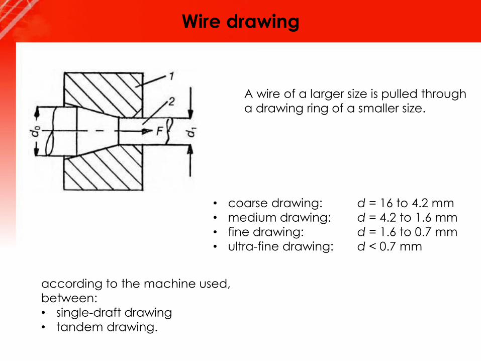
Wire drawing
A wire of a larger size is pulled through
a drawing ring of a smaller size.
• coarse drawing: d = 16 to 4.2 mm
• medium drawing: d = 4.2 to 1.6 mm
• fine drawing: d = 1.6 to 0.7 mm
• ultra-fine drawing: d < 0.7 mm
according to the machine used,
between:
• single-draft drawing
• tandem drawing.
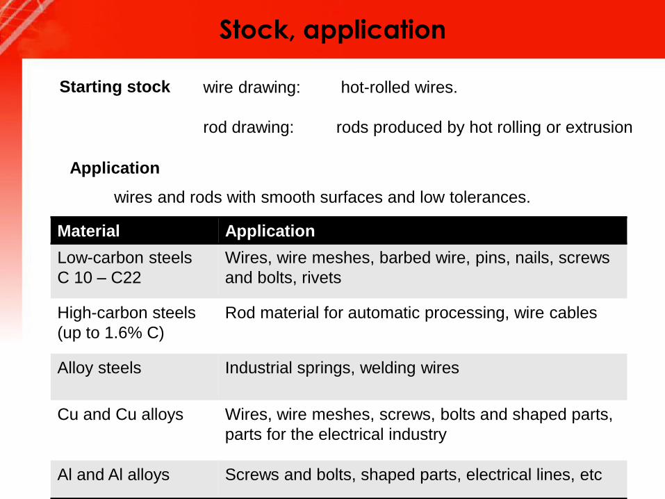
Stock, application
wires and rods with smooth surfaces and low tolerances.
Starting stock wire drawing: hot-rolled wires.
rod drawing: rods produced by hot rolling or extrusion
Application
Material Application
Low-carbon steels
C 10 – C22
Wires, wire meshes, barbed wire, pins, nails, screws
and bolts, rivets
High-carbon steels
(up to 1.6% C)
Rod material for automatic processing, wire cables
Alloy steels Industrial springs, welding wires
Cu and Cu alloys Wires, wire meshes, screws, bolts and shaped parts,
parts for the electrical industry
Al and Al alloys Screws and bolts, shaped parts, electrical lines, etc
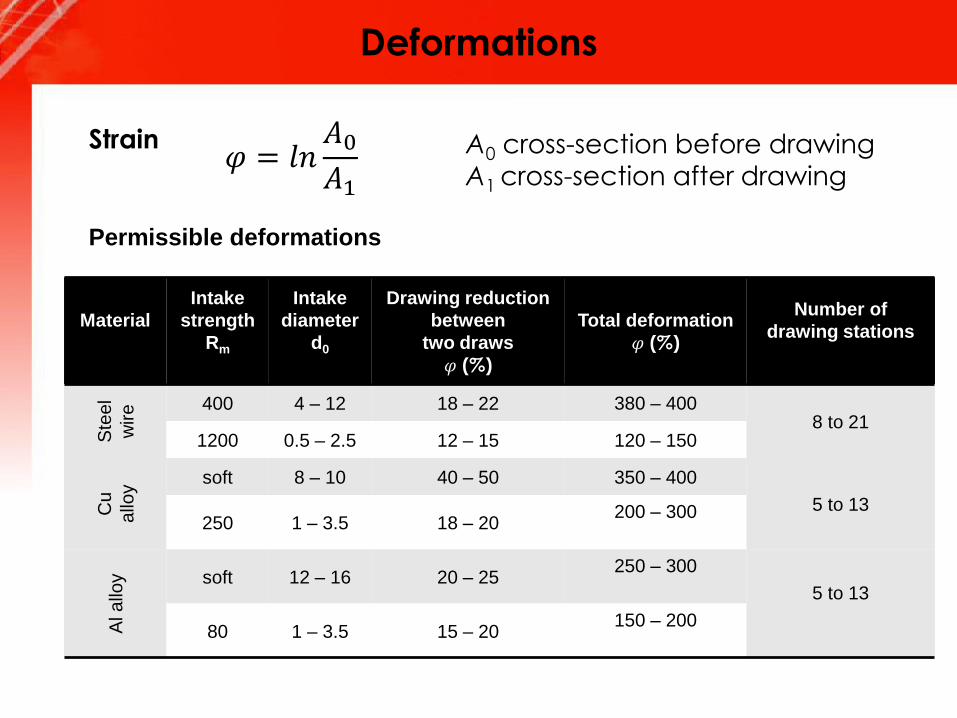
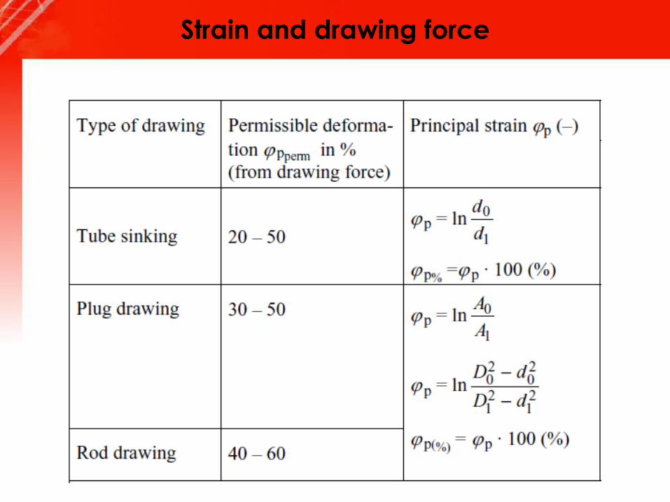
Deformations
Strain𝜑 = 𝑙𝑛
𝐴0𝐴1
A0 cross-section before drawing
A1 cross-section after drawing
Permissible deformations
Material
Intake
strength
Rm
Intake
diameter
d0
Drawing reduction
between
two draws
𝜑 (%)
Total deformation
𝜑 (%)
Number of
drawing stations
Ste
el
wire 400 4 – 12 18 – 22 380 – 400
8 to 211200 0.5 – 2.5 12 – 15 120 – 150
Cu
allo
y
soft 8 – 10 40 – 50 350 – 400
5 to 13250 1 – 3.5 18 – 20
200 – 300
Alallo
y soft 12 – 16 20 – 25 250 – 300
5 to 13
80 1 – 3.5 15 – 20 150 – 200
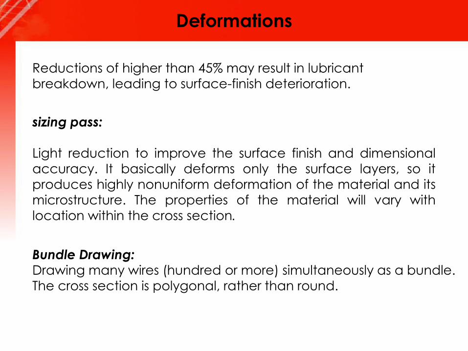
Deformations
Reductions of higher than 45% may result in lubricant
breakdown, leading to surface-finish deterioration.
sizing pass:
Light reduction to improve the surface finish and dimensional
accuracy. It basically deforms only the surface layers, so it
produces highly nonuniform deformation of the material and its
microstructure. The properties of the material will vary with
location within the cross section.
Bundle Drawing:Drawing many wires (hundred or more) simultaneously as a bundle.The cross section is polygonal, rather than round.
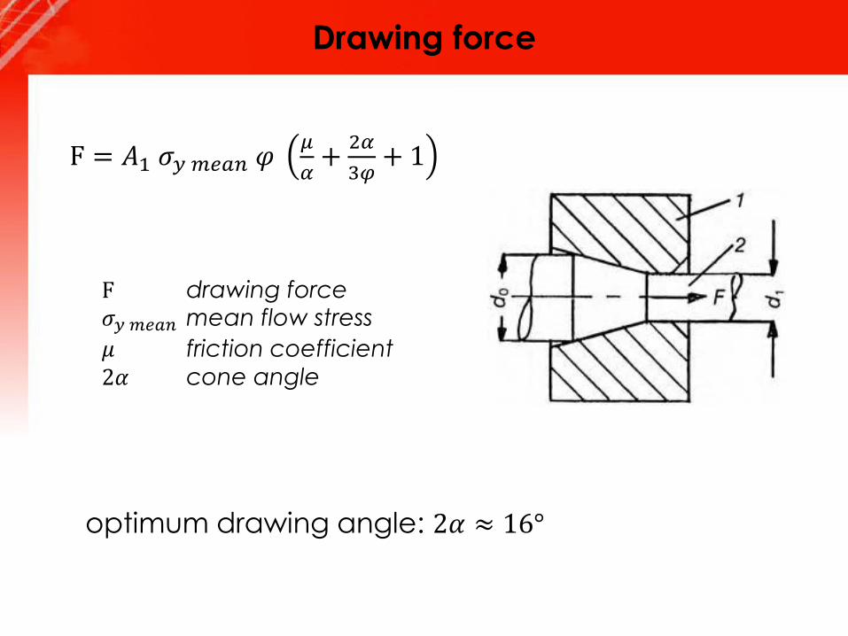
Drawing force
F = 𝐴1 𝜎𝑦 𝑚𝑒𝑎𝑛 𝜑𝜇
𝛼+
2𝛼
3𝜑+ 1
F drawing force𝜎𝑦 𝑚𝑒𝑎𝑛 mean flow stress
𝜇 friction coefficient
2𝛼 cone angle
optimum drawing angle: 2𝛼 ≈ 16°
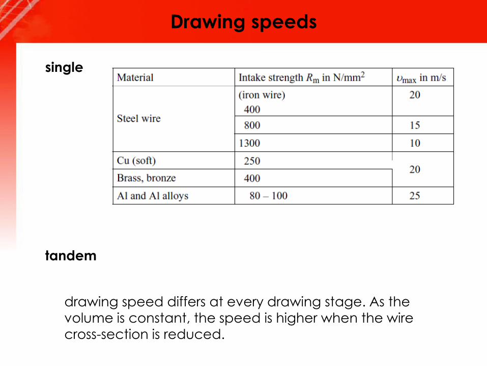
Drawing speeds
single
tandem
drawing speed differs at every drawing stage. As the
volume is constant, the speed is higher when the wire
cross-section is reduced.
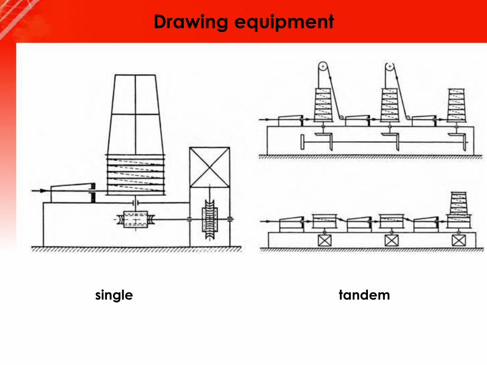
Drawing equipment
single tandem
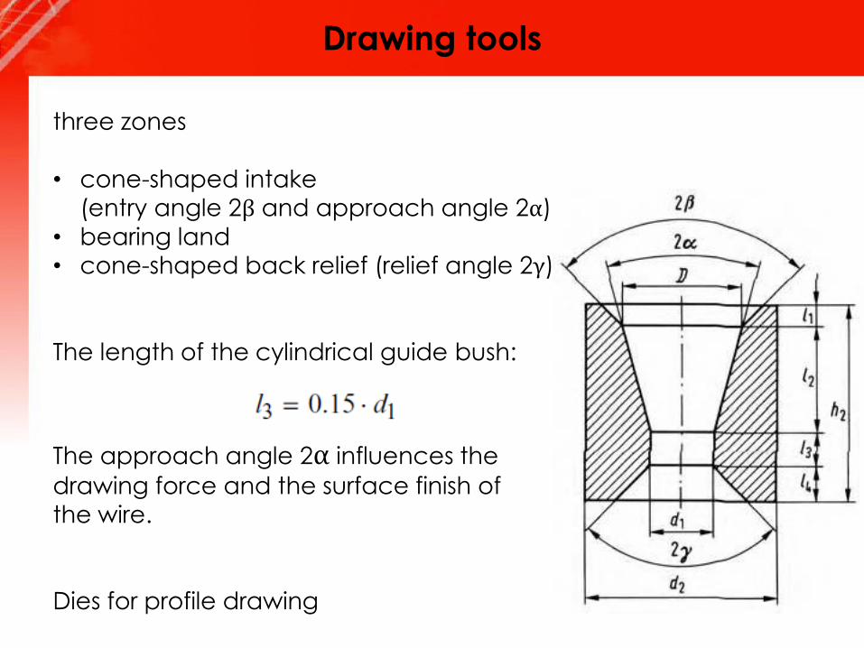
Drawing tools
three zones
• cone-shaped intake(entry angle 2β and approach angle 2α)
• bearing land• cone-shaped back relief (relief angle 2γ)
The length of the cylindrical guide bush:
The approach angle 2α influences the
drawing force and the surface finish of
the wire.
Dies for profile drawing
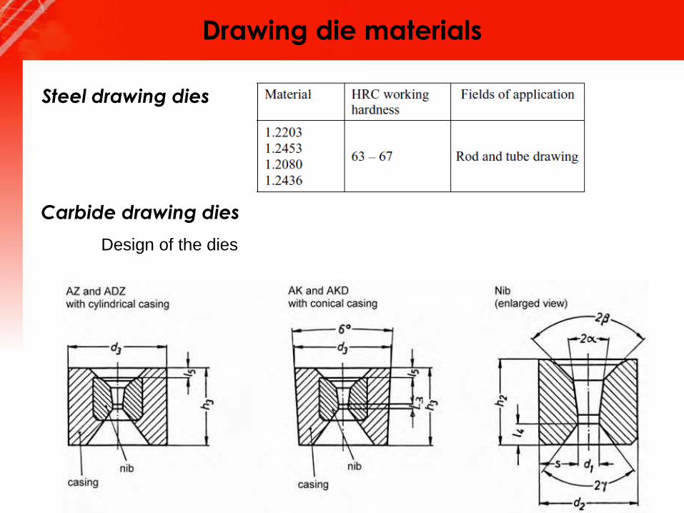
Drawing die materials
Steel drawing dies
Carbide drawing dies
Design of the dies

Drawing die materials
diamond drawing dies
For drawing fine and ultra-fine wires (0.01 mm to 1.5 mm)
made of copper, steel, tungsten and molybdenum.
The diamond is sintered into a steel casing.
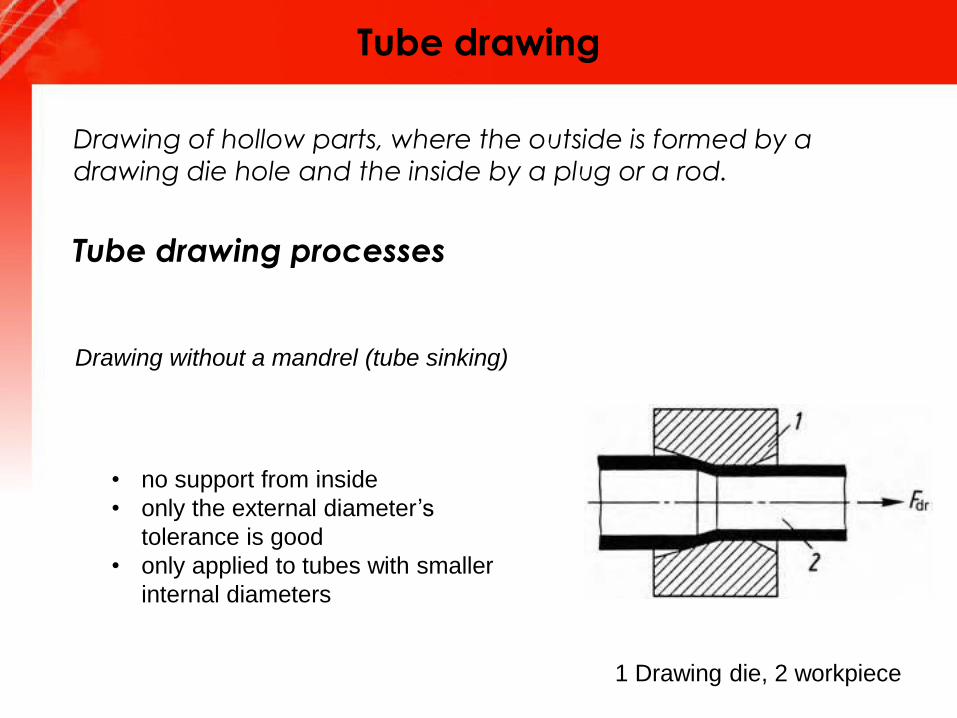
Tube drawing
Drawing of hollow parts, where the outside is formed by a
drawing die hole and the inside by a plug or a rod.
Tube drawing processes
Drawing without a mandrel (tube sinking)
• no support from inside
• only the external diameter’s
tolerance is good
• only applied to tubes with smaller
internal diameters
1 Drawing die, 2 workpiece

Tube drawing
Drawing over a stationary mandrel (plug)
1 Drawing ring, 2 workpiece, 3 mandrel, 4 plug
Drawing over a floating plug
1 Drawing ring, 2 workpiece, 3 floating plug
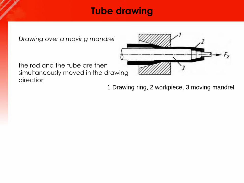
Tube drawing
Drawing over a moving mandrel
1 Drawing ring, 2 workpiece, 3 moving mandrel
the rod and the tube are then
simultaneously moved in the drawing
direction

Strain and drawing force
LimitThe limit for the deformation
comes from the required
drawing force
𝐹𝑑𝑟𝑎𝑤𝑖𝑛𝑔 < 𝐹𝑝𝑒𝑟𝑚.
𝐹𝑝𝑒𝑟𝑚. = 𝐴1𝜎𝑦𝑖𝑒𝑙𝑑 1
𝜎𝑦𝑖𝑒𝑙𝑑 1
𝐹𝑑𝑟𝑎𝑤𝑖𝑛𝑔 =𝐴1 𝜎𝑦𝑖𝑒𝑙𝑑 𝑚𝑒𝑎𝑛 𝜑
𝜂
𝜂 = 0.4 − 0.6 𝑓𝑜𝑟 𝜑 = 15%
𝜂 = 0.7 − 0.8 𝑓𝑜𝑟 𝜑 = 50%
Strain and drawing force
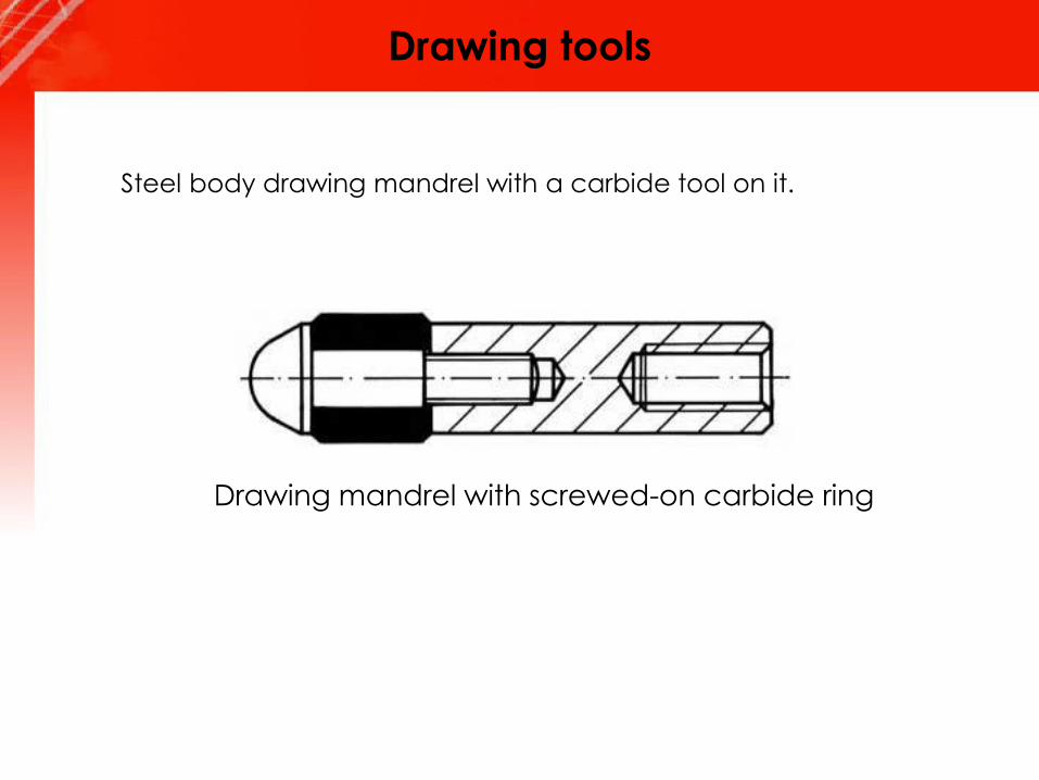
Drawing tools
Drawing mandrel with screwed-on carbide ring
Steel body drawing mandrel with a carbide tool on it.
Lubrication wire and tube drawing
tube drawing: difficulty of maintaining a sufficiently thick lubricant film at
the mandrel-tube interface.
Drawing of rods: a common method is phosphate coating
Wet drawing, in which the dies and the rod are immersed completely in the
Lubricant.
Dry drawing, in which the surface of the rod to be drawn is coated with a
lubricant by passing it through a box filled with the lubricant (stuffing box).
Metal coating, in which the rod or wire is coated with a soft metal, such as
copper or tin, that acts as a solid lubricant.
Ultrasonic vibration of the dies and mandrels; in this process, vibrations
reduce forces, improve surface finish and die life, and allow larger
reductions per pass without failure.
Defects - wire and tube drawing
rod and wire
center cracking (similar to those in extrusion)
seams longitudinal scratches or folds
(Seams may open up during subsequent
forming operations)
die marks
Cold forming - residual stresses
stress-corrosion cracking
warp deformation if a layer of material subsequently is
removed (machining, or grinding)