winter 17 examination 17403 - msbte.org.inmsbte.org.in/msbte_files/modalans/su18/17403.pdf · 1a)...
TRANSCRIPT

MAHARASHTRA STATE BOARD OF TECHNICAL EDUCATION (Autonomous)
(ISO/IEC - 27001 - 2013 Certified)
MODEL ANSWER WINTER– 17 EXAMINATION Subject Title: Automobile Manufacturing Processes Subject Code:
__________________________________________________________________________________________________
Page 1 of 27
17403
Important Instructions to examiners: 1) The answers should be examined by key words and not as word-to-word as given in the model answer scheme. 2) The model answer and the answer written by candidate may vary but the examiner may try to assess the
understanding level of the candidate. 3) The language errors such as grammatical, spelling errors should not be given more Importance (Not applicable for
subject English and Communication Skills. 4) While assessing figures, examiner may give credit for principal components indicated in the figure. The figures
drawn by candidate and model answer may vary. The examiner may give credit for any equivalent figure drawn. 5) Credits may be given step wise for numerical problems. In some cases, the assumed constant values may vary and
there may be some difference in the candidate’s answers and model answer.
6) In case of some questions credit may be given by judgement on part of examiner of relevant answer based on candidate’s understanding.
7) For programming language papers, credit may be given to any other program based on equivalent concept.
Q.
No.
Sub
Q. N.
Answer Marking
Scheme
1a) Attempt any SIX of the following 12
1a) i) Enlist any four forging components. 02
Ans: Forging Components:
(Any 4 suitable components , ½ mark each)
1. Connecting rod
2. Crankshaft
3. Camshaft
4. Alloy wheel
5. Drive shafts
6. Clutch hubs
7. Universal joints
8. Hand Tools
02
1a) ii) Enlist any four pressing operations. 02
Ans: Pressing Operations are as follows (Any four 2 marks: ½ mark each)
a) Blanking
b) Punching
c) Notching
d) Perforating
e) Trimming
f) Shaving
g) Slitting
h) Lancing
i) Bending
j) Drawing
k) Squeezing
02
MAHARASHTRA STATE BOARD OF TECHNICAL EDUCATION (Autonomous)
(ISO/IEC - 27001 - 2013 Certified)
MODEL ANSWER WINTER– 17 EXAMINATION Subject Title: Automobile Manufacturing Processes Subject Code:
__________________________________________________________________________________________________
Page 2 of 27
17403
iii) Define soldering process and enlist any two applications. 02
Answer: (Note: Definition -1mark, Application- ½ mark each)
Soldering:
Soldering is a method of joining two or more piece of metal by means of a fusible
alloy or metal, called solder, applied in the molten state.
Applications: (Any Two - 1/2 mark each)
1. Circuitry connections of radio & T.V. sets,
2. Wiring joints in electric connections & battery terminals,
3. Radiator brass tube,
4. Copper tubing,
5. Brass halved bearings,
6. Joints in sheet metal objects such as food cans,
7. Roof flashing,
8. Rain gutters,
9. Refrigeration and plumbing machine tools components,
10. Copper foil in stained glass work.
01
01
1a) iv) Give classification of welding process. 02
Ans: Classification of Welding Process (Brief classification 4 marks)
a. Arc welding
1) Carbon Arc Welding;
2) Shielded Metal Arc Welding (SMAW)
3) Submerged Arc Welding (SAW)
4) Metal Inert Gas Arc Welding (MIG, GMAW)
5) Tungsten Inert Gas Arc Welding (TIG, GTAW)
6) Electroslag Welding (ESW)
7) Plasma Arc Welding (PAW)
b. Resistance Welding (RW)
1) Spot Welding (RSW)
2) Flash Welding (FW)
3) Resistance Butt Welding (UW)
4) Seam Welding (RSEW)
c. Gas Welding (GW)
1) Oxyacetylene Welding (OAW)
2) Oxyhydrogen Welding (OHW)
3) Pressure Gas Welding (PGW)
d. Solid State Welding (SSW)
1) Forge Welding (FOW)
2) Cold Welding (CW)
3) Friction Welding (FRW)
4) Explosive Welding (EXW)
5) Diffusion Welding (DFW)
6) Ultrasonic Welding (USW)
e. Thermit Welding (TW)
02
MAHARASHTRA STATE BOARD OF TECHNICAL EDUCATION (Autonomous)
(ISO/IEC - 27001 - 2013 Certified)
MODEL ANSWER WINTER– 17 EXAMINATION Subject Title: Automobile Manufacturing Processes Subject Code:
__________________________________________________________________________________________________
Page 3 of 27
17403
f. Electron Beam Welding (EBW)
g. Laser Welding (LW)
1a) v) List any four factors affecting selection of surface finishing processes. 02
Ans: Following factors will affect the selection of surface finishing processes: ( ½
Mark Each)
1. Material of component
2. Basic machining operation carried out on component
3. Dimensions of component
4. Final value (in µm) of machined surfaces
5. Application of machined surfaces
1a) vi) Give the meaning of following ISO codes.
1) M02
2) M30
3) G90
4) G91
02
Ans: Meaning of ISO codes.( ½ Mark Each)
1) M02-Program end
2) M30-Program stop & Tape rewind
3) G90 :- Absolute Dimensioning
4) G91:- Incremental Dimensioning
02
1a) vii) Define NC and CNC machine. 02
Ans: Definition - (1 mark each)
NC Machine: “A system in which actions are controlled by direct insertions of
numerical data at some point.”
or
In simple words, “Numerical Control Machines means machine controlled by
number‟s programme”
or
“It is a programmable automation in which actions are controlled by means of
numbers, letters, & other symbols.”
CNC Machine: It is computer numerical control in which a dedicated computer
is used to perform all the basic NC functions.
01
01
1a) viii) Give any four advantages of forging processes. 02
Ans: Advantages of forging processes:(Any Four – ½ Mark Each)
1) Complex shaped parts can be forged
2) Mass production with greater accuracy is achieved.
3) It is very easy to maintain close tolerances.
4) Does not require highly skilled operator.
5) Better reproducibility.
6) Machining is not necessary to obtain final shape
02
1 B Attempt any TWO of the following 08
1b) i) Define forgeability and give any four forgeable materials used to produce
automotive components.
04

MAHARASHTRA STATE BOARD OF TECHNICAL EDUCATION (Autonomous)
(ISO/IEC - 27001 - 2013 Certified)
MODEL ANSWER WINTER– 17 EXAMINATION Subject Title: Automobile Manufacturing Processes Subject Code:
__________________________________________________________________________________________________
Page 4 of 27
17403
Ans: Forgeability (Definition 2 mark)
Forgeability can be defined as the tolerance of a metal or alloy for deformation
without failure.
OR
Forgeability is defined as the ability of a metal to change size and shape when
heated to required temperature and compressed by applying some pressure.
Forgeable Materials: (Any Four : ½ Mark each)
1) Aluminum alloys
2) Magnesium alloys
3) Copper alloys.
4) Carbon and low alloy steels
5) Martensitic stainless steels
6) Austenitic stainless steels
7) Nickel alloys
8) Titanium alloys
9) Columbium alloys
10) Tantalum alloys
11) Molybdenum alloys
12) Tungsten alloys
13) Beryllium.
02
02
1b) ii) Enlist any four operations carried out in forging process and explain
fullering with neat sketch.
04
Ans: Operations carried out in forging process: ( any four operations: ½ mark each,
sketch 1mark and explanation 1mark)
a) Upsetting
b) Drawing Down
c) Setting down
d) Welding
e) Bending
f) Cutting
g) Punching
Fullering:
In fullering, the material cross section is decreased and length is increased. Figure
shows that the bottom fuller is kept in the anvil hole with the heated stock over
the fuller. The top fuller is then kept above the stock and then with the sledge
hammer. The force is applied on the top fuller which results in decreasing the
02
01
01
MAHARASHTRA STATE BOARD OF TECHNICAL EDUCATION (Autonomous)
(ISO/IEC - 27001 - 2013 Certified)
MODEL ANSWER WINTER– 17 EXAMINATION Subject Title: Automobile Manufacturing Processes Subject Code:
__________________________________________________________________________________________________
Page 5 of 27
17403
cross section at that point.
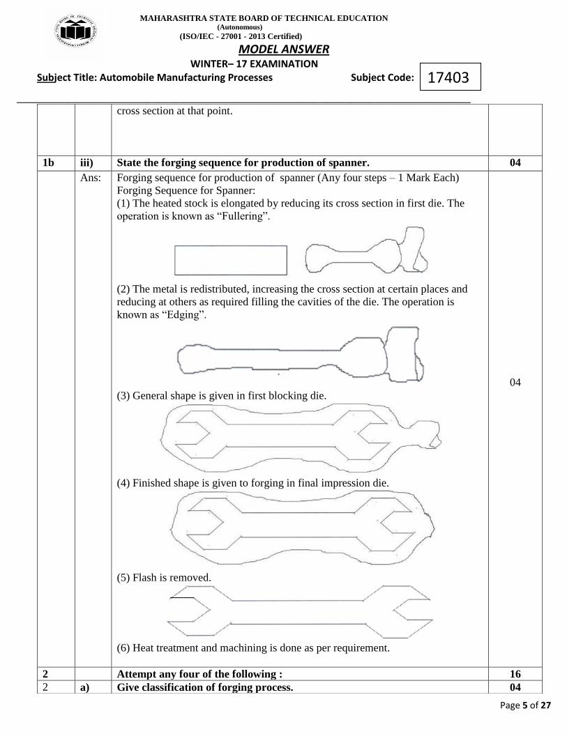
1b iii) State the forging sequence for production of spanner. 04
Ans: Forging sequence for production of spanner (Any four steps – 1 Mark Each)
Forging Sequence for Spanner:
(1) The heated stock is elongated by reducing its cross section in first die. The
operation is known as “Fullering”.
(2) The metal is redistributed, increasing the cross section at certain places and
reducing at others as required filling the cavities of the die. The operation is
known as “Edging”.
(3) General shape is given in first blocking die.
(4) Finished shape is given to forging in final impression die.
(5) Flash is removed.
(6) Heat treatment and machining is done as per requirement.
04
2 Attempt any four of the following : 16
2 a) Give classification of forging process. 04

MAHARASHTRA STATE BOARD OF TECHNICAL EDUCATION (Autonomous)
(ISO/IEC - 27001 - 2013 Certified)
MODEL ANSWER WINTER– 17 EXAMINATION Subject Title: Automobile Manufacturing Processes Subject Code:
__________________________________________________________________________________________________
Page 6 of 27
17403
Ans: Classification of forging process -
I. Open die forging:
a) Hand forging
b) Power forging:
i. Hammer forging
ii. Press forging
II. Close die forging:
a) Drop forging
b) Press forging
c) Machine forging
OR
04
Or
04
2 b) Explain forging sequence for camshaft. 04
Forging process for manufacturing Camshaft:(Any four steps – 1 Mark Each)
i) Stock is redistributed and size is increased at certain places & reduced at others
by rolled forging.
ii) after preliminary roll forging, the stock is again roll forged.
iii) This stock is then forged in first impression or blocking die.
04

MAHARASHTRA STATE BOARD OF TECHNICAL EDUCATION (Autonomous)
(ISO/IEC - 27001 - 2013 Certified)
MODEL ANSWER WINTER– 17 EXAMINATION Subject Title: Automobile Manufacturing Processes Subject Code:
__________________________________________________________________________________________________
Page 7 of 27
17403
iv) final shape is given to the forging in next blocking die.
v) finished part is trimmed in blanking die to remove excess metal or flash.
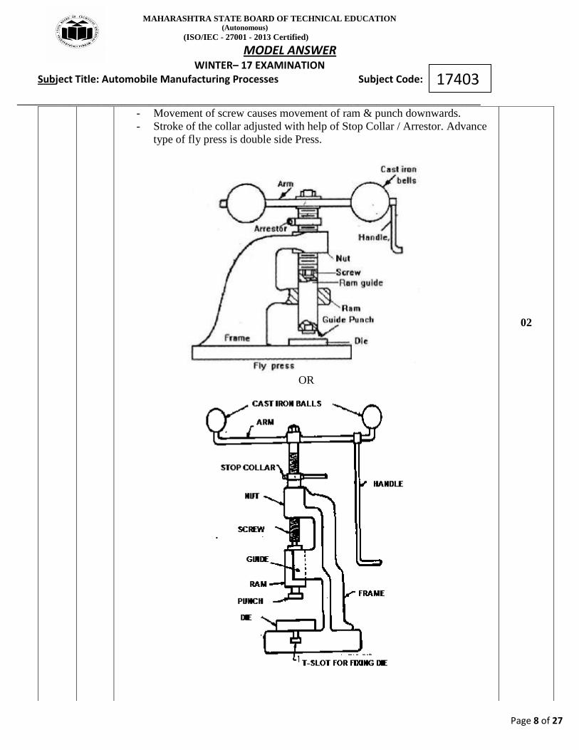
c) Describe fly press with neat sketch. 04
Ans: (02 Marks for Description of Fly press, 02 Marks for Neat Sketch)
Fly Press :
- It is simplest type of all presses, called as hand press / ball press/single
side fly press.
- It consists of robust cast iron frame. Top portion of frame forms the nut.
- Vertical screw which can go through the nut. Screw carries an arm.
- Arm supports two cast iron weights (balls) at two ends. Handle used for
rotating the arm.
- Frame extended below the nut to form guides. Ram attached at the bottom
of the screw.
- Ram carries punch at its bottom. Die is fixed at the press base.
- Sheet metal placed over the die. Arm gets quick rotation with the help of
handle.
- Heavy balls stores kinetic energy for long time movement of screw.
02
MAHARASHTRA STATE BOARD OF TECHNICAL EDUCATION (Autonomous)
(ISO/IEC - 27001 - 2013 Certified)
MODEL ANSWER WINTER– 17 EXAMINATION Subject Title: Automobile Manufacturing Processes Subject Code:
__________________________________________________________________________________________________
Page 8 of 27
17403
- Movement of screw causes movement of ram & punch downwards.
- Stroke of the collar adjusted with help of Stop Collar / Arrestor. Advance
type of fly press is double side Press.
OR
02
MAHARASHTRA STATE BOARD OF TECHNICAL EDUCATION (Autonomous)
(ISO/IEC - 27001 - 2013 Certified)
MODEL ANSWER WINTER– 17 EXAMINATION Subject Title: Automobile Manufacturing Processes Subject Code:
__________________________________________________________________________________________________
Page 9 of 27
17403
2 d) Enlist any four die accessories and explain use of stops. 04
Ans: Die accessories: (any Four ½ mark each)
1. Stops
2. Pilots
3. Knock Out
4. Strippers
5. Pressure pad
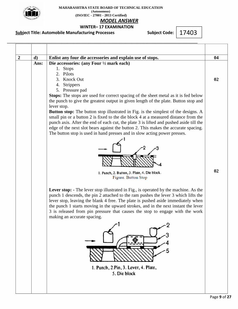
Stops: The stops are used for correct spacing of the sheet metal as it is fed below
the punch to give the greatest output in given length of the plate. Button stop and
lever stop.
Button stop: The button stop illustrated in Fig. is the simplest of the designs. A
small pin or a button 2 is fixed to the die block 4 at a measured distance from the
punch axis. After the end of each cut, the plate 3 is lifted and pushed aside till the
edge of the next slot bears against the button 2. This makes the accurate spacing.
The button stop is used in hand presses and in slow acting power presses.
Lever stop: - The lever stop illustrated in Fig., is operated by the machine. As the
punch 1 descends, the pin 2 attached to the ram pushes the lever 3 which lifts the
lever stop, leaving the blank 4 free. The plate is pushed aside immediately when
the punch 1 starts moving in the upward strokes, and in the next instant the lever
3 is released from pin pressure that causes the stop to engage with the work
making an accurate spacing.
02
02

MAHARASHTRA STATE BOARD OF TECHNICAL EDUCATION (Autonomous)
(ISO/IEC - 27001 - 2013 Certified)
MODEL ANSWER WINTER– 17 EXAMINATION Subject Title: Automobile Manufacturing Processes Subject Code:
__________________________________________________________________________________________________
Page 10 of 27
17403
2 e) Difference between compound and combination die. 04
Ans: Difference between compound and combination die. (Any Four – 1 Mark Each)
Compound die Combination die
1. Any two cutting operations can be
performed at one station.
1. Both cutting and forming operations
can be performed at one station.
2. Both operations performed in a
single stoke of press
2. Two separate strokes of press.
3. Jobs produced with high accuracy
and close tolerance.
3. Care need to be taken to produce
jobs with high accuracy and close
tolerance.
4. Blanking, piercing or punching
operations are performed.
4. Blanking, drawing, bending
operations performed.
5. e.g. washer 5. e.g. drawing cup shaped part.
04
2 f) Draw and identify parts of standard die set. 04
Ans: Answer: (Sketch :-2 marks, labelling -2marks)
04
3 Attempt any FOUR of the following: 16
a) State “Plane washer” making process with use of combination die. 04
Ans: (Explanation 02 Marks Figure 02 Mark)
(Note: The plain washers can be produced by using Compound die or Progressive
MAHARASHTRA STATE BOARD OF TECHNICAL EDUCATION (Autonomous)
(ISO/IEC - 27001 - 2013 Certified)
MODEL ANSWER WINTER– 17 EXAMINATION Subject Title: Automobile Manufacturing Processes Subject Code:
__________________________________________________________________________________________________
Page 11 of 27
17403
die. It is not possible to use combination die for making plain washers, so
consider compound die or progressive die for answer. However credit should be
given to any other suitable answer using combination die.)
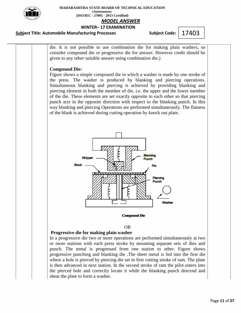
Compound Die: Figure shows a simple compound die in which a washer is made by one stroke of
the press. The washer is produced by blanking and piercing operations.
Simultaneous blanking and piercing is achieved by providing blanking and
piercing element in both the member of die, i.e. the upper and the lower member
of the die. These elements are set exactly opposite to each other so that piercing
punch acts in the opposite direction with respect to the blanking punch. In this
way blanking and piercing Operations are performed simultaneously. The flatness
of the blank is achieved during cutting operation by knock out plate.
OR
Progressive die for making plain washer
In a progressive die two or more operations are performed simultaneously at two
or more stations with each press stroke by mounting separate sets of dies and
punch. The metal is progressed from one station to other. Figure shows
progressive punching and blanking die .The sheet metal is fed into the first die
where a hole is pierced by piercing die set in first cutting stroke of ram. The plate
is then advanced in next station. In the second stroke of ram the pilot enters into
the pierced hole and correctly locate it while the blanking punch descend and
shear the plate to form a washer.

MAHARASHTRA STATE BOARD OF TECHNICAL EDUCATION (Autonomous)
(ISO/IEC - 27001 - 2013 Certified)
MODEL ANSWER WINTER– 17 EXAMINATION Subject Title: Automobile Manufacturing Processes Subject Code:
__________________________________________________________________________________________________
Page 12 of 27
17403
1. Stop 2.sheet metal 3.pilot 4.blanking punch 5.ram 6.piercing punch 7.stripper
8.die
3 b) State the working principle of gas welding. 04
Working principle of gas welding: (Explanation 02 Marks, Fig 02Mark)
Gas Welding is a fusion welding process. It joins metals, using the heat of
combustion of the oxygen/air and combustible gas (i.e. acetylene, hydrogen,
propane, or butane) mixture. The purpose of flame is to heat and melt the parent
metal and filler rod of the joint. The intense heat produced melts the edges of
parts and fuses together to form the welded, generally with the addition of a filler
metal. The torch mixes a combustible gas with oxygen in the proper ratio and
flow rate providing combustion process at a required temperature. The flame
temperature is determined by a type of the combustible gas and proportion of
oxygen in the combustion mixture: 4500°F - 6300°F (2500°C - 3500°C).
Depending on the proportion of the fuel gas and oxygen in the combustion
mixture, the flame may be chemically neutral (content of the gases), oxidizing
(excess of oxygen), and carburizing (excess of fuel gas). Welding does not
require the components to be forced together under pressure until the weld is
forms and solidifies.
Fig. Gas Welding
02
02

MAHARASHTRA STATE BOARD OF TECHNICAL EDUCATION (Autonomous)
(ISO/IEC - 27001 - 2013 Certified)
MODEL ANSWER WINTER– 17 EXAMINATION Subject Title: Automobile Manufacturing Processes Subject Code:
__________________________________________________________________________________________________
Page 13 of 27
17403
3 c) Differentiate between TIG and MIG. 04
Ans: (Each point 1 Mark i.e. 1x4 = 4 Marks)
Sr. No TIG MIG
1 In Tungsten Inert Gas arc
welding, non- consumable
tungsten electrode is used
In Metal Inert Gas arc welding,
consumable metallic electrode is
used
2 Both AC and DC supply may be
used
DC with reverse polarity is used
3 Filler metal may or may not be
used
Filler metal not used as electrode
itself serve both purposes of
0producing arc and filler metal
4 Not used for welding plates
thicker than 6 mm
Best suited for welding jobs
thicker than 6 mm
5 Welding speed is low Welding speed is fast
6 Electrode feed not required Electrode need to be feed at
constant speed from wire reel
7 Penetration not so much deeper Deeper penetration is obtained
8 Requires skilled operator Less skilled operator can do the
job
04
3 d) Explain the resistance Welding 04
Ans: Resistance Welding: (Explanation 02 Marks, Fig 02Mark)
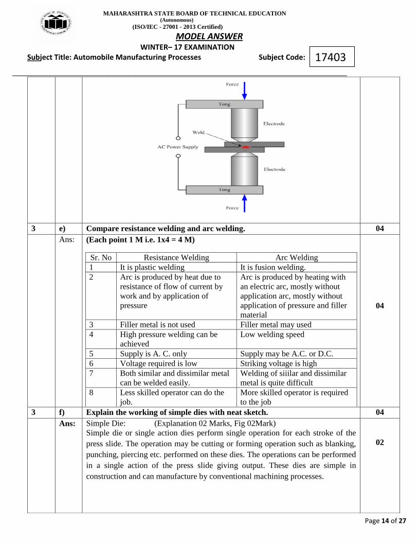
Resistance welding is a group of welding processes wherein coalescence is
produced by the heat obtained from resistance of the work to the flow of electric
current in a circuit of which the work is a part and by the application of pressure.
No filler material is needed.
Resistance welding is employed to join overlapping strips, sheets or plates of
metal at small areas .The pieces are assembled between two electrodes, which
must possess high electrical and thermal conductivity and retain the required
strength at high temperatures, so they are made of pure copper for a limited
amount of service, and of alloys of copper or tungsten, or copper and chromium
for continuous working. When current is turned on, the pieces are heated at their
contacts to a welding temperature, and with the aid of mechanical pressure the
electrodes are forced against the metal to be welded.
02
MAHARASHTRA STATE BOARD OF TECHNICAL EDUCATION (Autonomous)
(ISO/IEC - 27001 - 2013 Certified)
MODEL ANSWER WINTER– 17 EXAMINATION Subject Title: Automobile Manufacturing Processes Subject Code:
__________________________________________________________________________________________________
Page 14 of 27
17403
3 e) Compare resistance welding and arc welding. 04
Ans: (Each point 1 M i.e. 1x4 = 4 M)
Sr. No Resistance Welding Arc Welding
1 It is plastic welding It is fusion welding.
2 Arc is produced by heat due to
resistance of flow of current by
work and by application of
pressure
Arc is produced by heating with
an electric arc, mostly without
application arc, mostly without
application of pressure and filler
material
3 Filler metal is not used Filler metal may used
4 High pressure welding can be
achieved
Low welding speed
5 Supply is A. C. only Supply may be A.C. or D.C.
6 Voltage required is low Striking voltage is high
7 Both similar and dissimilar metal
can be welded easily.
Welding of siiilar and dissimilar
metal is quite difficult
8 Less skilled operator can do the
job.
More skilled operator is required
to the job
04
3 f) Explain the working of simple dies with neat sketch. 04
Ans: Simple Die: (Explanation 02 Marks, Fig 02Mark)
Simple die or single action dies perform single operation for each stroke of the
press slide. The operation may be cutting or forming operation such as blanking,
punching, piercing etc. performed on these dies. The operations can be performed
in a single action of the press slide giving output. These dies are simple in
construction and can manufacture by conventional machining processes.
02

MAHARASHTRA STATE BOARD OF TECHNICAL EDUCATION (Autonomous)
(ISO/IEC - 27001 - 2013 Certified)
MODEL ANSWER WINTER– 17 EXAMINATION Subject Title: Automobile Manufacturing Processes Subject Code:
__________________________________________________________________________________________________
Page 15 of 27
17403
OR
02
4 Attempt any four of the following 16
4 a) Sketch and label different types of gas welding flames. Also give application
of any one flame.
(Sketches of 3 Types- 3 marks, applications of any one -1 marks)
1) Neutral Flame: - A neutral flame is obtained when equal amounts of oxygen
and acetylene are mixed and burnt in a torch.
Applications: - stainless steel, cast iron, copper ,mild steel and aluminum
01
MAHARASHTRA STATE BOARD OF TECHNICAL EDUCATION (Autonomous)
(ISO/IEC - 27001 - 2013 Certified)
MODEL ANSWER WINTER– 17 EXAMINATION Subject Title: Automobile Manufacturing Processes Subject Code:
__________________________________________________________________________________________________
Page 16 of 27
17403
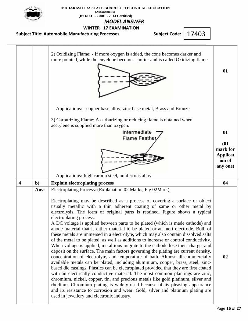
2) Oxidizing Flame: - If more oxygen is added, the cone becomes darker and
more pointed, while the envelope becomes shorter and is called Oxidizing flame
Applications: - copper base alloy, zinc base metal, Brass and Bronze
3) Carburizing Flame: A carburizing or reducing flame is obtained when
acetylene is supplied more than oxygen.
Applications:-high carbon steel, nonferrous alloy
01
01
(01
mark for
Applicat
ion of
any one)
4 b) Explain electroplating process 04
Ans: Electroplating Process: (Explanation 02 Marks, Fig 02Mark)
Electroplating may be described as a process of covering a surface or object
usually metallic with a thin adherent coating of same or other metal by
electrolysis. The form of original parts is retained. Figure shows a typical
electroplating process.
A DC voltage is applied between parts to be plated (which is made cathode) and
anode material that is either material to be plated or an inert electrode. Both of
these metals are immersed in a electrolyte, which may also contain dissolved salts
of the metal to be plated, as well as additions to increase or control conductivity.
When voltage is applied, metal ions migrate to the cathode lose their charge, and
deposit on the surface. The main factors governing the plating are current density,
concentration of electrolyte, and temperature of bath. Almost all commercially
available metals can be plated, including aluminium, copper, brass, steel, zinc-
based die castings. Plastics can be electroplated provided that they are first coated
with an electrically conductive material. The most common plantings are zinc,
chromium, nickel, copper, tin, and precious metals like gold platinum, silver and
rhodium. Chromium plating is widely used because of its pleasing appearance
and its resistance to corrosion and wear. Gold, silver and platinum plating are
used in jewellery and electronic industry.
02

MAHARASHTRA STATE BOARD OF TECHNICAL EDUCATION (Autonomous)
(ISO/IEC - 27001 - 2013 Certified)
MODEL ANSWER WINTER– 17 EXAMINATION Subject Title: Automobile Manufacturing Processes Subject Code:
__________________________________________________________________________________________________
Page 17 of 27
17403
02
4 c) Describe buffing process and enlist its any two applications. 04
Ans: Buffing process :- (Explanation 02 Marks, Fig 02Mark)
Buffing is used to give a much higher, lustrous, reflective finish that cannot be
obtained by polishing. The buffing process consists in applying very fine
abrasives with rotating wheel. Buffing wheels are made of discs of linen, cotton,
broad cloth and canvass. They are made more or less firm by the amount of
stitching used to fasten the layers of the cloth together. The abrasive is mixed
with binder and is applied either on the buffing wheel or on the work. The
abrasives may consist of iron oxide chromium oxide, emery etc. The binder is a
paste consisting of wax mixed with grease, paraffin and kerosene, or turpentine
and other liquid.
In this process, work piece is brought in contact with a revolving, cloth buffing
wheel that has been charged with very fine abrasive. The abrasives removes
minute amount of metal from the work piece, eliminate fine scratch marks and
produce a very smooth surface. Buffing is used to apply high luster to the work
piece.
Applications: - Automobiles, motor-cycles, boats, bicycles, sporting items, tools,
store fixtures, commercial and residential hardware and household utensils and
appliances.
02

MAHARASHTRA STATE BOARD OF TECHNICAL EDUCATION (Autonomous)
(ISO/IEC - 27001 - 2013 Certified)
MODEL ANSWER WINTER– 17 EXAMINATION Subject Title: Automobile Manufacturing Processes Subject Code:
__________________________________________________________________________________________________
Page 18 of 27
17403
Fig. Buffing process 02
4 d) Differentiate with acid cleaning and alkaline cleaning process.
04
Ans: (For any four points 4 marks)
Acid Cleaning Process Alkaline Cleaning Process
1 Acid cleaning is used for
removal of light rust, tarnish,
scale, drawing compounds, oil,
and grease
It is used for the removal of oil,
grease, shop dirt, and compounds
from polishing, buffing, and
drawing operations.
2 the cleaner is a solution of
acids or acid salts instead of
alkaline salts.
In this type of cleaning, the
cleaner used is the combination
of a solution of certain alkaline
salts and detergents in water
3 Acid cleaning does not work
efficiently when heavy
coatings of oil and grease are
there on the work-piece.
It is very effective process.
4 It is expensive process. This method is considered to be
the least expensive and most
popular for mass production.
5 Hydrochloric acid, Sulphuric
acid are the acid cleaning
agents.
caustic soda, tri-sodium
phosphate, silicates, borates, or
carbonates are the alkaline
agents.
04
4 e) Explain absolute and incremental co-ordinate system with neat sketch 04
Ans: 1. Absolute Co- ordinate system: (Explanation – 01 mark & Sketch –
01mark)
In Cartesian co–ordinate geometry system using absolute measurement. Each
point is always specified using same zero of given co–ordinate system as shown
in fig. It is a system in which all moving commands are referred to one reference
point, which is the origin / set point. All the position commands are given from
zero point. The main advantage of this system is that it forces the operator to stop
the machine in case of interruptions.
01
01

MAHARASHTRA STATE BOARD OF TECHNICAL EDUCATION (Autonomous)
(ISO/IEC - 27001 - 2013 Certified)
MODEL ANSWER WINTER– 17 EXAMINATION Subject Title: Automobile Manufacturing Processes Subject Code:
__________________________________________________________________________________________________
Page 19 of 27
17403
2. Absolute Co- ordinate system: (Explanation – 01 mark & Sketch–
01mark)
In Cartesian co–ordinate geometry system using incremental measurement. Each
point is always specified using the path differential from the preceding point
position. So in such a programming, controller must store and process additional
path measurement, as shown in fig. It is a system in which the reference point to
the next instruction is the end point of the preceding operation. Each data of
applied to the system as a distance increment, measured from preceding point.
01
01
4 f) Give classification of CNC machines. 04
Ans: Classification of CNC machines. (Brief classification 4 marks)
A. According to control loop feedback system:
1) Open – loop system
2) Closed – loop system
B. According to type of tool motion control system:
1) Finite positioning control system:
a) Point – to – point system
b) Straight cut system
2) Continuous path system:
a) Two axes contouring
b) Two & half axes contouring
MAHARASHTRA STATE BOARD OF TECHNICAL EDUCATION (Autonomous)
(ISO/IEC - 27001 - 2013 Certified)
MODEL ANSWER WINTER– 17 EXAMINATION Subject Title: Automobile Manufacturing Processes Subject Code:
__________________________________________________________________________________________________
Page 20 of 27
17403
c) Three axes contouring
d) Multi – axis contouring
C. According to programming methods:
1) Absolute programming method
2) Incremental programming method
D. According to type of controller:
1) NC based controller system
2) CNC based controller system
E. According to Operation of Machine
1) Swiss-style lathe / Swiss turning center
2) Combination lathe / 3-in-1 machine
3) Mini-lathe and micro-lathe
4) Wheel lathe
04
5 Attempt any FOUR of the following: (4 x 4) 16
5 (a) With the help of block diagram explain closed loop control CNC system. 04
Ans: (02 Marks for Block Diagram And 02 Marks For Explanation.)
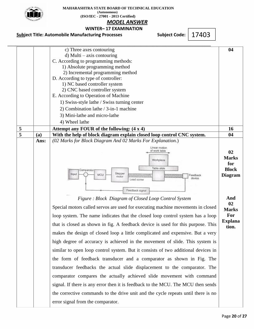
Figure : Block Diagram of Closed Loop Control System
Special motors called servos are used for executing machine movements in closed
loop system. The name indicates that the closed loop control system has a loop
that is closed as shown in fig. A feedback device is used for this purpose. This
makes the design of closed loop a little complicated and expensive. But a very
high degree of accuracy is achieved in the movement of slide. This system is
similar to open loop control system. But it consists of two additional devices in
the form of feedback transducer and a comparator as shown in Fig. The
transducer feedbacks the actual slide displacement to the comparator. The
comparator compares the actually achieved slide movement with command
signal. If there is any error then it is feedback to the MCU. The MCU then sends
the corrective commands to the drive unit and the cycle repeats until there is no
error signal from the comparator.
02
Marks
for
Block
Diagram
And
02
Marks
For
Explana
tion.
MAHARASHTRA STATE BOARD OF TECHNICAL EDUCATION (Autonomous)
(ISO/IEC - 27001 - 2013 Certified)
MODEL ANSWER WINTER– 17 EXAMINATION Subject Title: Automobile Manufacturing Processes Subject Code:
__________________________________________________________________________________________________
Page 21 of 27
17403
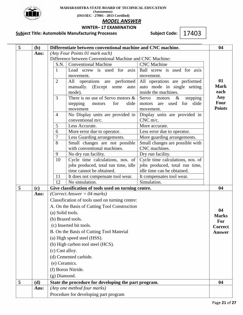
5 (b) Differentiate between conventional machine and CNC machine. 04
Ans: (Any Four Points 01 mark each)
Difference between Conventional Machine and CNC Machine:
S.N. Conventional Machine CNC Machine
1 Lead screw is used for axis
movement.
Ball screw is used for axis
movement.
2 All operations are performed
manually. (Except some auto
mode).
All operations are performed
auto mode in single setting
inside the machines.
3 There is no use of Servo motors &
stepping motors for slide
movement
Servo motors & stepping
motors are used for slide
movement.
4 No Display units are provided in
conventional m/c.
Display units are provided in
CNC m/c.
5 Less Accurate. More accurate.
6 More error due to operator. Less error due to operator.
7 Less Guarding arrangements. More guarding arrangements.
8 Small changes are not possible
with conventional machines.
Small changes are possible with
CNC machines.
9 No dry run facility. Dry run facility.
10 Cycle time calculations, nos. of
jobs produced, total run time, idle
time cannot be obtained.
Cycle time calculations, nos. of
jobs produced, total run time,
idle time can be obtained.
11 It does not compensate tool wear. It compensates tool wear.
12 No simulation. Simulation.
01
Mark
each
Any
Four
Points
5 (c) Give classification of tools used on turning centre. 04
Ans: (Correct Answer = 04 marks)
Classification of tools used on turning centre:
A. On the Basis of Cutting Tool Construction
(a) Solid tools.
(b) Brazed tools.
(c) Inserted bit tools.
B. On the Basis of Cutting Tool Material
(a) High speed steel (HSS).
(b) High carbon tool steel (HCS).
(c) Cast alloy.
(d) Cemented carbide.
(e) Ceramics.
(f) Boron Nitride.
(g) Diamond.
04
Marks
For
Correct
Answer
5 (d) State the procedure for developing the part program. 04
Ans: (Any one method four marks)
Procedure for developing part program

MAHARASHTRA STATE BOARD OF TECHNICAL EDUCATION (Autonomous)
(ISO/IEC - 27001 - 2013 Certified)
MODEL ANSWER WINTER– 17 EXAMINATION Subject Title: Automobile Manufacturing Processes Subject Code:
__________________________________________________________________________________________________
Page 22 of 27
17403
There are two methods of part programming:-
A) Manual Part Programming:
To prepare a part program using the manual method
1) The programmer writes the machining instructions on a special form called a
part programming manuscript. The manuscript is a listing of the relative tool and
work piece location.
2) The NC tape is prepared directly from the manuscript.
3) Define the axis coordinates in relation to the work part.
4) Define safe (target point)point & origin point (work zero)
5) The tape is inserted to read the first block in to the system.
6) The function like machining, tool changing, spindle ON/OFF ,coolant
ON/OFF, program stop and tape rewinding are carried out as per the program.
OR
B) Computer –Assisted Part Programming (CAPP): -
This method is useful for most critical and complex parts. The part programmer
and the computer are the main tool in this method.
1) The part programmer first defines the work part geometry.
2) He specifies the operation sequence and tool path.
3)The computer interprets the list of part programming instructions, performs the
necessary calculations to convert this into a detailed set of machine tool motion
commands, and then controls a tape device to prepare the tape.
4) The tape is verified for accuracy.
5)The NC system machine makes the part according to the instructions on tape
04
Marks
For
Any
One
method
5 (e) State the function of „G‟ Codes and „M‟ codes with any two examples. 04
Ans: (02 Marks For Functions And 02 Marks For Its Example)
„G‟ Codes ( Preparatory Functions)
The preparatory function instructs the machine tool to get prepared for the
operation to follow,
the preparatory function is represented by two digits preceded by letter „G‟
e.g. G02, G04, G97, G96, etc.
(i) G00 – Rapid Positioning,
(ii) G01- Linear Interpolation ,
(iii)G90 – Absolute Programming etc.
M- codes (Miscellaneous function)
The Miscellaneous function word is used to specify certain Miscellaneous
function or auxiliary functions which do not relate to the dimensional movements
of the machine.
The Miscellaneous function is represented by two digits preceded by letter „M‟
02
Marks
For
Function
s
And
02
Marks
For
Its
Example

MAHARASHTRA STATE BOARD OF TECHNICAL EDUCATION (Autonomous)
(ISO/IEC - 27001 - 2013 Certified)
MODEL ANSWER WINTER– 17 EXAMINATION Subject Title: Automobile Manufacturing Processes Subject Code:
__________________________________________________________________________________________________
Page 23 of 27
17403
e.g. M00, M05, M08, M30 etc.
i) M02 - Program end
ii) M06 - Tool change
iii) M08 – Coolant ON
5 (f) Differentiate between lapping and honing process. 04
Ans: (01 Marks For Each Points )
S.
N.
Lapping Honing
1 Lapping is a finishing
process in which tool used is
called lap.
Honing is a finishing process in
which tool used is called hone.
2 The lapping process involves
passing a part between one or
two large flat-lap plates or
wheels.
Tool has combined reciprocating
and rotary motion of tool.
3 Cutting action takes place by
fluid that contains an
abrasive.
Cutting action takes place by
abrasive sticks.
4 The Process is used to
corrects minor imperfections
of shape, refines surface
finish (mirrors finishes are
common)
The process is used to remove
tool marks of previous
operations.
Used for flat and slightly
spherical
Used for round holes
5 Applications: Precision Plug
Gauges, Metallic Bearing
Surfaces, Optical Lenses, etc.
Applications: Cylinders of an IC
engine, air bearing spindles,
gears etc.
6 Used to achieve super-flat
surfaces and incredibly tight
tolerances on parts that
require accuracy at the
microscopic level.
Used to improve certain form
characteristics such as
cylindricity, surface finish, or
sphericity.
7 Lapping removes much less
material than honing
Honing removes more material
than Lapping
01
Marks
For
Each
Points
6 Attempt any TWO of the following: (2 x 8) 16
6 (a) Prepare a part program for following component. Also give co-ordinate
system. Assume suitable data if required. Refer Fig. No. 1.
08

MAHARASHTRA STATE BOARD OF TECHNICAL EDUCATION (Autonomous)
(ISO/IEC - 27001 - 2013 Certified)
MODEL ANSWER WINTER– 17 EXAMINATION Subject Title: Automobile Manufacturing Processes Subject Code:
__________________________________________________________________________________________________
Page 24 of 27
17403
Ans:
Point X-
Coordinate
Z-
Coordinate
P0 0.0 2.0
P1 0.0 0.0
P2 22.0 0.0
P3 30.0 -35.0
P4 30.0 -65.0
P5 36.0 -68.0
P6 36.0 -103.0
P7 50.0 -103.0
P8 50.0 -113.0
P9 60.0 -113.0
(02 Mark for Coordinate System with figure and 06 Marks for Correct Program )
Fig. No. 1
Assumptions (may differ for every
student)
Spindle Speed=1000RPM, Feed Rate=0.2 mm/rev. Carbide Insert Used DNMG
150404, Tool Holder Used PDLNL 2525 M15
PROGRAM:
O1234;
N001 G28 U0.0 W0.0;
N002 G90 G97 G98 G21;
N003 M06 T0101 M08;
N004 M04 S1000;
N005 G00 X0.0 Z2.0;
N006 G01 X22.0 Z0.0 F0.2;
N007 G01 X30.0 Z-35.0;
N008 G01 X30.0 Z-65.0;
N009 G03 X36.0 Z-68.0 R3.0;
N010 G01 X36.0 Z-103.0;
N011 G01 X50.0 Z-103.0;
N012 G01 X50.0 Z-113.0;
N013 G01 X60.0 Z-113.0;
N014 M05 M09;
N015 G28 U0.0 W0.0;
N016 M30;
02
Mark
For
Coordin
ate
System
And
06
Marks
For
Correct
Program
6 (b) Prepare a part program for following component (refer Fig. No. 2). Assume
suitable data if required. Assume plate thickness is 50 mm.
08

MAHARASHTRA STATE BOARD OF TECHNICAL EDUCATION (Autonomous)
(ISO/IEC - 27001 - 2013 Certified)
MODEL ANSWER WINTER– 17 EXAMINATION Subject Title: Automobile Manufacturing Processes Subject Code:
__________________________________________________________________________________________________
Page 25 of 27
17403
Ans:
Point X-
Coordina
te
Y-
Coordinate
Z-
Coordinate
P0 -10.0 -10.0 0.0
P1 0.0 0.0 -55.0
P2 80.0 0.0 -55.0
P3 80.0 50.0 -55.0
P4 50.0 0.0 -55.0
P1 0.0 0.0 -55.0
P5 10.0 10.0 -55.0
P6 10.0 40.0 -55.0
P7 70.0 40.0 -55.0
P0 -10.0 -10.0 0.0
(02 Mark For Coordinate System with figure and 06 Marks For Correct
Program)
[NOTE :Program written for drilling operation only can be considered for full
marks]
Fig. No 2
Assumptions: (may differ for
every student)
Tool No.1: Solid Carbide End Mill of 25 mm Diameter X 60 mm Flute Length X
110 mm Overall Length is used.
Tool No 2: Solid Carbide Drill 10 mm X 65 mm X 110 mm is used.
PROGRAM;
O1234; (Side Milling of Plate 50X 80 X 50 mm Thick)
N001 G28 X0.0 Y0.0 Z0.0;
N002 G90 G99 G97 G42 G21;
N003 M06 T0101 M08;
N004 M03 S750;
N005 G00 X-10.0 Y-10.0 Z0.0;
N006 G01 X0.0 Y0.0 Z-55.0 F150.0;
N007 G01 X80.0 Y0.0;
N008 G01 X80.0 Y50.0;
N009 G01 X0.0 Y50.0;
N010 G01 X0.0 Y0.0;
N011 G01 X -10.0 Y-10.0 Z0.0;
N012 M05 M09;
N013 G40;
N014 G28X0.0 Y0.0 Z0.0;
N015 M06 T0202 M08; (Drilling of Diameter 10 mm holes X 3Nos.)
N016 M03 S500;
N017 G00 X10.0 Y10.0 Z2.0;
N018 G01 Z-55.0 F50.0;
N019 G01 Z2.0;
N020 G00 X10.0 Y40.0;
N021 G01 Z-55.0;
N022 G01 Z2.0;
N023 G00 X70.0 Y40.0;
02
Mark
For
Coordin
ate
System
And
06
Marks
For
Correct
Program

MAHARASHTRA STATE BOARD OF TECHNICAL EDUCATION (Autonomous)
(ISO/IEC - 27001 - 2013 Certified)
MODEL ANSWER WINTER– 17 EXAMINATION Subject Title: Automobile Manufacturing Processes Subject Code:
__________________________________________________________________________________________________
Page 26 of 27
17403
N024 G01 Z-55.0;
N025 G01 Z2.0;
N026 G28 X0.0 Y0.0 Z0.0;
N027 M05 M09;
N028 M30;
6 (c) Describe with neat sketch working of progressive die. Also write functions of
any four parts of progressive die.
08
Ans: (02 Marks For Sketch, 02 Marks For Description, 01 Mark For Function Of Each
Part)
Figure: Progressive Die
In a progressive die two or more operations are performed simultaneously at two
or more stations with each press stroke by mounting separate sets of dies and
punch. The metal is progressed from one station to other. Figure shows
progressive punching and blanking die. The sheet metal is fed into the first die
where a hole is pierced by piercing die set in first cutting stroke of ram. The plate
is then advanced in next station. In the second stroke of ram the pilot enters into
the pierced hole and correctly locate it while the blanking punch descend and
shear the plate to form a washer
Functions :
(1) Bolster Plate:
It is part of press machine attached to the bed, which supports and hold the die
block at required position.
(2) Die:
It is a female part of a complete tool, used for producing work in press.
(3) Punch:
It is a male part of die assembly, use to insert into the die for producing work in
press
(a) Piercing Punch:
The sheet metal is fed into the first die where a hole is pierced by piercing punch
02
Marks
For
Sketch,
02
Marks
For
Descript
ion,
01
Mark
For
Function
Of
Each
Part.

MAHARASHTRA STATE BOARD OF TECHNICAL EDUCATION (Autonomous)
(ISO/IEC - 27001 - 2013 Certified)
MODEL ANSWER WINTER– 17 EXAMINATION Subject Title: Automobile Manufacturing Processes Subject Code:
__________________________________________________________________________________________________
Page 27 of 27
17403
in first cutting stroke of ram.
(b) Blanking Punch: In the second stroke of ram the pilot of blanking punch
enters into the pierced hole and shear the plate to form a washer
(4) Guide Pin (Pilot): To locate the blanking punch correctly, while the blanking
punch descend.
(5) Punch Holder: To hold the punch/s in proper position.
(6) Stripper Plate: It is used to strip the metal strip from the punch or die. It also
guides the t metal sheet