winspice3 user's manual - universidad de...
TRANSCRIPT
WinSpice3 User's Manual
15 March, 2001
Mike Smith
Based on Spice 3 User Manual
by
T.Quarles, A.R.Newton, D.O.Pederson, A.Sangiovanni-Vincentelli
Department of Electrical Engineering and Computer Sciences
University of California
Berkeley, Ca., 94720

WinSpice3 User Manual
i 27/09/01
Table Of Contents
1 Introduction ................................................................................................................................... 11.1 Installation .............................................................................................................................. 11.2 Running WinSpice3 ............................................................................................................... 21.3 Uninstalling WinSpice3.......................................................................................................... 41.4 Command Line Options.......................................................................................................... 4
2 TYPES OF ANALYSIS ............................................................................................................... 52.1 DC Analysis............................................................................................................................ 52.2 AC Small-Signal Analysis...................................................................................................... 52.3 Transient Analysis .................................................................................................................. 52.4 Pole-Zero Analysis ................................................................................................................. 52.5 Small-Signal Distortion Analysis ........................................................................................... 52.6 Sensitivity Analysis ................................................................................................................ 62.7 Noise Analysis........................................................................................................................ 62.8 Analysis At Different Temperatures....................................................................................... 6
3 CIRCUIT DESCRIPTION ............................................................................................................ 83.1 General Structure And Conventions....................................................................................... 83.2 Title Line, Comment Lines And .END Line .......................................................................... 8
3.2.1 Title Line .......................................................................................................................... 83.2.2 .END Line......................................................................................................................... 93.2.3 Comments......................................................................................................................... 9
3.3 .MODEL: Device Models....................................................................................................... 93.4 Subcircuits .............................................................................................................................. 10
3.4.1 .SUBCKT Line ................................................................................................................. 103.4.2 .ENDS Line ...................................................................................................................... 113.4.3 Xxxxx: Subcircuit Calls.................................................................................................... 11
3.5 Combining Files ..................................................................................................................... 113.5.1 .INCLUDE Lines.............................................................................................................. 113.5.2 .LIB Lines......................................................................................................................... 11
4 CIRCUIT ELEMENTS AND MODELS ...................................................................................... 134.1 Elementary Devices................................................................................................................ 13
4.1.1 Rxxxx: Resistors............................................................................................................... 134.1.1.1 Simple Resistors ..................................................................................................... 134.1.1.2 Semiconductor Resistors ........................................................................................ 134.1.1.3 Semiconductor Resistor Model (R) ........................................................................ 13
4.1.2 Cxxxx: Capacitors ............................................................................................................ 144.1.2.1 Simple Capacitors................................................................................................... 144.1.2.2 Semiconductor Capacitors...................................................................................... 154.1.2.3 Semiconductor Capacitor Model (C)...................................................................... 15
4.1.3 Lxxxx: Inductors .............................................................................................................. 164.1.4 Kxxxx: Coupled (Mutual) Inductors ................................................................................ 164.1.5 Sxxxx and Wxxxx: Switches............................................................................................ 16
4.1.5.1 Sxxxx: Voltage Controlled Switch......................................................................... 164.1.5.2 Wxxxx: Current Controlled Switch........................................................................ 164.1.5.3 Switch Model (SW/CSW) ...................................................................................... 17
4.2 Voltage And Current Sources................................................................................................. 194.2.1 Ixxxx and Vxxxx: Independent Sources........................................................................... 19
4.2.1.1 PULSE(): Pulse ...................................................................................................... 194.2.1.2 SIN(): Sinusoidal.................................................................................................... 204.2.1.3 EXP(): Exponential ................................................................................................ 214.2.1.4 PWL(): Piece-Wise Linear ..................................................................................... 214.2.1.5 SFFM(): Single-Frequency FM.............................................................................. 22
4.2.2 Linear Dependent Sources................................................................................................ 224.2.2.1 Gxxxx: Linear Voltage-Controlled Current Sources.............................................. 224.2.2.2 Exxxx: Linear Voltage-Controlled Voltage Sources.............................................. 224.2.2.3 Fxxxx: Linear Current-Controlled Current Sources............................................... 23
WinSpice3 User Manual
ii 27/09/01
4.2.2.4 Hxxxx: Linear Current-Controlled Voltage Sources.............................................. 234.2.3 Non-linear Dependent Sources using POLY() ................................................................. 23
4.2.3.1 Voltage-Controlled Current Sources ...................................................................... 244.2.3.2 Voltage-Controlled Voltage Sources...................................................................... 244.2.3.3 Current-Controlled Current Sources....................................................................... 254.2.3.4 Current-Controlled Voltage Sources ...................................................................... 25
4.2.4 Bxxxx: Non-linear Dependent Sources ............................................................................ 264.3 Transmission Lines................................................................................................................. 27
4.3.1 Txxxx: Lossless Transmission Lines................................................................................ 274.3.2 Oxxxx: Lossy Transmission Lines ................................................................................... 27
4.3.2.1 Lossy Transmission Line Model (LTRA) .............................................................. 274.3.3 Uxxxx: Uniform Distributed RC Lines (Lossy) ............................................................... 29
4.3.3.1 Uniform Distributed RC Model (URC).................................................................. 294.4 Transistors And Diodes .......................................................................................................... 30
4.4.1 Dxxxx: Junction Diodes ................................................................................................... 314.4.1.1 Diode Model (D) .................................................................................................... 31
4.4.2 Qxxxx: Bipolar Junction Transistors (BJTs) .................................................................... 324.4.2.1 BJT Models (NPN/PNP) ........................................................................................ 33
4.4.3 Jxxxx: Junction Field-Effect Transistors (JFETs) ............................................................ 354.4.3.1 JFET Models (NJF/PJF) ......................................................................................... 35
4.4.4 Mxxxx: MOSFETs ........................................................................................................... 364.4.4.1 MOSFET Models (NMOS/PMOS) ........................................................................ 37
4.4.5 Zxxxx: MESFETs............................................................................................................. 424.4.5.1 MESFET Models (NMF/PMF) .............................................................................. 42
5 ANALYSES AND OUTPUT CONTROL .................................................................................... 445.1 .OPTIONS: Simulator Variables ............................................................................................ 445.2 Initial Conditions .................................................................................................................... 47
5.2.1 .NODESET: Specify Initial Node Voltage Guesses........................................................ 475.2.2 .IC: Set Initial Conditions................................................................................................. 48
5.3 Analyses ................................................................................................................................. 485.3.1 .AC: Small-Signal AC Analysis ...................................................................................... 485.3.2 .DC: DC Transfer Function .............................................................................................. 495.3.3 .DISTO: Distortion Analysis ........................................................................................... 495.3.4 .NOISE: Noise Analysis .................................................................................................. 505.3.5 .OP: Operating Point Analysis......................................................................................... 515.3.6 .PZ: Pole-Zero Analysis ................................................................................................... 525.3.7 .SENS: DC or Small-Signal AC Sensitivity Analysis ..................................................... 525.3.8 .TF: Transfer Function Analysis...................................................................................... 525.3.9 .TRAN: Transient Analysis ............................................................................................. 53
5.4 Batch Output........................................................................................................................... 535.4.1 .SAVE Lines..................................................................................................................... 535.4.2 .PRINT Lines.................................................................................................................... 545.4.3 .PLOT Lines ..................................................................................................................... 555.4.4 .FOUR: Fourier Analysis of Transient Analysis Output ................................................. 55
6 INTERACTIVE INTERPRETER ................................................................................................. 566.1 Command Interpretation......................................................................................................... 566.2 Variables................................................................................................................................. 566.3 Variable Substitution .............................................................................................................. 616.4 Redirection ............................................................................................................................. 626.5 Vectors & Scalars ................................................................................................................... 626.6 Expressions............................................................................................................................. 636.7 Functions ................................................................................................................................ 646.8 Constants ................................................................................................................................ 666.9 History Substitutions .............................................................................................................. 66
6.9.1 Events and Their Specifications ....................................................................................... 666.9.2 Selectors ........................................................................................................................... 676.9.3 Modifiers .......................................................................................................................... 676.9.4 Special Conventions ......................................................................................................... 68
6.10 Filename Expansions.............................................................................................................. 69
WinSpice3 User Manual
iii 27/09/01
6.11 Control Structures................................................................................................................... 696.11.1 While - End ...................................................................................................................... 696.11.2 Repeat - End ..................................................................................................................... 696.11.3 Dowhile - End................................................................................................................... 696.11.4 Foreach - End ................................................................................................................... 706.11.5 If - Then - Else.................................................................................................................. 706.11.6 Label ................................................................................................................................. 706.11.7 Goto .................................................................................................................................. 706.11.8 Continue ........................................................................................................................... 706.11.9 Break ................................................................................................................................ 70
6.12 Commands.............................................................................................................................. 716.12.1 Ac: Perform an AC frequency response analysis ............................................................. 716.12.2 Alias: Create an alias for a command .............................................................................. 716.12.3 Alter: Change a device or model parameter .................................................................... 716.12.4 Asciiplot: Plot values using old-style character plots ...................................................... 716.12.5 Bug: Mail a bug report .................................................................................................... 726.12.6 Cd: Change directory........................................................................................................ 726.12.7 Cross: Create a new vector ............................................................................................... 726.12.8 Dc: Perform a DC-sweep analysis.................................................................................... 726.12.9 Define: Define a function ................................................................................................ 726.12.10 Delete: Remove a trace or breakpoint ............................................................................ 736.12.11 Destroy: Delete a data set (plot) ..................................................................................... 736.12.12 Diff: Compare vectors ................................................................................................... 736.12.13 Display: List known vectors and types.......................................................................... 736.12.14 Disto: Perform a distortion analysis .............................................................................. 736.12.15 Echo: Print text .............................................................................................................. 746.12.16 Edit: Edit the current circuit ........................................................................................... 746.12.17 Fourier: Perform a fourier transform.............................................................................. 746.12.18 Hardcopy: Save a plot to a file for printing ................................................................... 746.12.19 Help: Print summaries of WinSpice3 commands .......................................................... 746.12.20 History: Review previous commands............................................................................ 746.12.21 Iplot: Incremental plot .................................................................................................... 756.12.22 Let: Assign a value to a vector ...................................................................................... 756.12.23 Linearize: Interpolate to a linear scale........................................................................... 756.12.24 Listing: Print a listing of the current circuit.................................................................... 766.12.25 Load: Load rawfile data................................................................................................. 766.12.26 Noise: Perform a noise analysis...................................................................................... 766.12.27 Op: Perform an operating point analysis ........................................................................ 766.12.28 Plot: Plot values on the display....................................................................................... 766.12.29 Print: Print values .......................................................................................................... 776.12.30 Pz: Perform a Pole-Zero Analysis ................................................................................. 776.12.31 Quit: Leave WinSpice3 ................................................................................................. 776.12.32 Rawfile: Send further results directly to a rawfile.......................................................... 786.12.33 Reset: Reset an analysis.................................................................................................. 786.12.34 Reshape: Alter the dimensionality or dimensions of a vector ........................................ 786.12.35 Resume: Continue a simulation after a stop ................................................................... 786.12.36 Run: Run analysis from the input file............................................................................. 786.12.37 Rusage: Resource usage ................................................................................................. 786.12.38 Save: Save a set of output vectors ................................................................................. 806.12.39 Sens: Run a sensitivity analysis..................................................................................... 806.12.40 Set: Set the value of a variable ...................................................................................... 806.12.41 Setcirc: Change the current circuit ................................................................................. 806.12.42 Setplot: Switch the current set of vectors ...................................................................... 816.12.43 Setscale: Set the scale for a plot ..................................................................................... 816.12.44 Settype: Set the type of a vector .................................................................................... 826.12.45 Shell: Call the command interpreter .............................................................................. 826.12.46 Shift: Alter a list variable............................................................................................... 836.12.47 Show: List device state ................................................................................................... 836.12.48 Showmod: List model parameter values......................................................................... 83
WinSpice3 User Manual
iv 27/09/01
6.12.49 Source: Read a WinSpice3 input file............................................................................. 836.12.50 Spec: Generate a Fourier transform vector..................................................................... 846.12.51 Status: Display breakpoint and trace information .......................................................... 846.12.52 Step: Run a fixed number of time points ....................................................................... 856.12.53 Stop: Set a breakpoint.................................................................................................... 856.12.54 Strcmp: Compare strings ................................................................................................ 856.12.55 Tf: Run a Transfer Function analysis ............................................................................. 866.12.56 Trace: Trace nodes ......................................................................................................... 866.12.57 Tran: Perform a transient analysis .................................................................................. 866.12.58 Transpose: Swap the elements in a multi-dimensional data set...................................... 866.12.59 Tutorial: Display hypertext help..................................................................................... 866.12.60 Unalias: Retract an alias ................................................................................................ 866.12.61 Undefine: Retract a definition ....................................................................................... 876.12.62 Unlet: Delete vectors ...................................................................................................... 876.12.63 Unset: Clear a variable .................................................................................................. 876.12.64 Version: Print the version of WinSpice......................................................................... 876.12.65 Where: Identify troublesome node or device ................................................................ 876.12.66 Write: Write data to a file ............................................................................................... 87
6.13 Miscellaneous ......................................................................................................................... 886.14 Bugs........................................................................................................................................ 88
7 CONVERGENCE ......................................................................................................................... 897.1 Solving Convergence Problems.............................................................................................. 897.2 What is Convergence? (or Non-Convergence!) ..................................................................... 897.3 SPICE3 - New Convergence Algorithms ............................................................................... 907.4 Non-Convergence Error Messages/Indications ...................................................................... 907.5 Convergence Solutions........................................................................................................... 90
7.5.1 DC Convergence Solutions .............................................................................................. 907.5.2 DC Sweep Convergence Solutions................................................................................... 927.5.3 Transient Convergence Solutions..................................................................................... 937.5.4 Special Cases .................................................................................................................... 947.5.5 WinSpice3 Convergence Helpers..................................................................................... 94
8 BIBLIOGRAPHY ......................................................................................................................... 969 APPENDIX A: EXAMPLE CIRCUITS ...................................................................................... 97
9.1 Circuit 1: Differential Pair ..................................................................................................... 979.2 Circuit 2: MOSFET Characterisation .................................................................................... 979.3 Circuit 3: RTL Inverter.......................................................................................................... 979.4 Circuit 4: Four-Bit Binary Adder .......................................................................................... 989.5 Circuit 5: Transmission-Line Inverter ................................................................................... 99
10 APPENDIX B: MODEL AND DEVICE PARAMETERS.......................................................... 10010.1 URC: Uniform R.C. line........................................................................................................ 10010.2 ASRC: Arbitrary Source........................................................................................................ 10110.3 BJT: Bipolar Junction Transistor........................................................................................... 10110.4 BSIM1: Berkeley Short Channel IGFET Model ................................................................... 10410.5 BSIM2: Berkeley Short Channel IGFET Model ................................................................... 10610.6 Capacitor: Fixed capacitor..................................................................................................... 11010.7 CCCS: Current controlled current source.............................................................................. 11110.8 CCVS: Linear current controlled current source ................................................................... 11110.9 CSwitch: Current controlled ideal switch.............................................................................. 11210.10 Diode: Junction Diode model ................................................................................................ 11210.11 Inductor: Inductors ................................................................................................................ 11310.12 mutual: Mutual inductors....................................................................................................... 11410.13 Isource: Independent current source...................................................................................... 11410.14 JFET: Junction Field effect transistor.................................................................................... 11510.15 LTRA: Lossy transmission line ............................................................................................. 11610.16 MES: GaAs MESFET model ................................................................................................ 11710.17 Mos1: Level 1 MOSFET model with Meyer capacitance model .......................................... 11810.18 Mos2: Level 2 MOSFET model with Meyer capacitance model .......................................... 12010.19 Mos3: Level 3 MOSFET model with Meyer capacitance model .......................................... 12310.20 Mos6: Level 6 MOSFET model with Meyer capacitance model .......................................... 127

WinSpice3 User Manual
v 27/09/01
10.21 Resistor: Simple resistor ........................................................................................................ 13010.22 Switch: Ideal voltage controlled switch................................................................................. 13010.23 Tranline: Lossless transmission line...................................................................................... 13110.24 VCCS: Voltage controlled current source ............................................................................. 13110.25 VCVS: Voltage controlled voltage source ............................................................................ 13210.26 Vsource: Independent voltage source.................................................................................... 132
WinSpice3 User Manual
1 27/09/01
1 INTRODUCTION
WinSpice3 is a general-purpose circuit simulation program for non-linear DC, non-linear transient, andlinear AC analyses. Circuits may contain resistors, capacitors, inductors, mutual inductors, independentvoltage and current sources, four types of dependent sources, lossless and lossy transmission lines (twoseparate implementations), switches, uniform distributed RC lines, and the five most commonsemiconductor devices: diodes, BJTs, JFETs, MESFETs, and MOSFETs.
WinSpice3 is based on Spice3F41 which in turn was developed from SPICE2G.6. While WinSpice3 isbeing developed to include new features, it continues to support those capabilities and models whichremain in extensive use in the SPICE2 program.
1.1 Installation
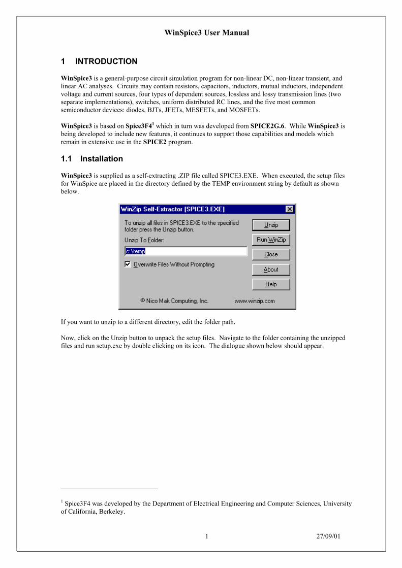
WinSpice3 is supplied as a self-extracting .ZIP file called SPICE3.EXE. When executed, the setup filesfor WinSpice are placed in the directory defined by the TEMP environment string by default as shownbelow.
If you want to unzip to a different directory, edit the folder path.
Now, click on the Unzip button to unpack the setup files. Navigate to the folder containing the unzippedfiles and run setup.exe by double clicking on its icon. The dialogue shown below should appear.
1 Spice3F4 was developed by the Department of Electrical Engineering and Computer Sciences, Universityof California, Berkeley.

WinSpice3 User Manual
2 27/09/01
Make sure you read the readme.txt file which might contain some useful information and give details ofhow to contact the author (it is amazing how many people don’t read ANY of the documents – when indoubt RTFM!!).
Note that WinSpice3 adds no files to the Windows directories!
1.2 Running WinSpice3
Click on ‘Start’, point to ‘Programs’ and find the WinSpice3 popout. Click on ‘wspice3’ to run theprogram. The following window (or something like it) will appear:-
This window emulates a terminal window as is seen in versions of Spice3 running on Unix machines.
At this point, WinSpice3 will accept numerous commands typed in at the keyboard (see section 6.12 fordetails of the commands supported). The command interpreter is based on the Unix C-shell and it ispossible to write complex programs with it. For example, the setplot command (see section 6.12.42) isimplemented using such a ‘script’ (look in the lib\script directory in the directory WinSpice3 is installed infor the script).
However, since you haven’t read that far yet, the quickest way of running a simulation is to open one of thecircuit files in the examples directory. To do this, click ‘File’, ‘Open’. The dialogue box shown below willappear.

WinSpice3 User Manual
3 27/09/01
Double click on ‘Examples’ and then double click on ‘Phonoamp.cir’. As soon as the file is loaded, itbegins simulating the circuit and generating plot windows as it goes. Make one of the plot windows theactive window.
The plot can be resized by dragging the window border. The plot can be printed to the default printer byclicking on ‘File’, ‘Print’. The plot can be copied to the clipboard by clicking ‘Edit’, ‘Copy’ and thenpasting the plot into a document e.g.
You can also zoom into an area of a plot by clicking on the graph and dragging the mouse to select therequired area. A zoomed-in graph will be displayed when you release the mouse button.

WinSpice3 User Manual
4 27/09/01
A tutorial, in the form of a Word document, is also provided and you should run this tutorial to understandsome of the basic concepts of WinSpice3.
1.3 Uninstalling WinSpice3
Use the ‘Add/Remove Programs’ applet in the Control Panel to uninstall the program.
1.4 Command Line Optionswspice3 [-n][-b][-i][-r rawfile] [input file ...]
Options are:
-n (or -N)Don't try to source the file .spiceinit upon start-up. Normally WinSpice3 tries to find the filein the current directory, and if it is not found then in the directory containing the WinSpice3program.
-bBatch mode. Simulates the input file and writes the results to a rawfile. After the circuit hasbeen simulated, WinSpice will exit.
-iInteractive mode (default). WinSpice simulates the input file and continues running. It thenmonitors the state of the input file. If it changes in any way, WinSpice will reload the circuit.
-r rawfileSpecifies the name of the output rawfile. This causes WinSpice to output results directly tothe file.
Further arguments to WinSpice3 are taken to be SPICE3 input files, which are read and saved (if runningin batch mode then they are run immediately). WinSpice3 accepts most SPICE2 input files, and outputASCII plots, Fourier analyses, and node printouts as specified in .plot, .four, and .print cards. If an outparameter is given on a .width card, the effect is the same as set width = .... Since WinSpice3 ASCII plotsdo not use multiple ranges, however, if vectors together on a .plot card have different ranges they do notprovide as much information as they would in SPICE2. The output of WinSpice3 is also much lessverbose than SPICE2, in that the only data printed is that requested by the above cards.

WinSpice3 User Manual
5 27/09/01
2 TYPES OF ANALYSIS
2.1 DC Analysis
The DC analysis portion of SPICE determines the DC operating point of the circuit with inductors shortedand capacitors opened. The DC analysis options are specified on the .DC, .TF, and .OP control lines. ADC analysis is automatically performed prior to a transient analysis to determine the transient initialconditions, and prior to an AC small-signal analysis to determine the linearized, small-signal models fornon-linear devices. If requested, the DC small-signal value of a transfer function (ratio of output variableto input source), input resistance, and output resistance is also computed as a part of the DC solution. TheDC analysis can also be used to generate DC transfer curves: a specified independent voltage or currentsource is stepped over a user-specified range and the DC output variables are stored for each sequentialsource value.
2.2 AC Small-Signal Analysis
The AC small-signal portion of WinSpice3 computes the AC output variables as a function of frequency.The program first computes the DC operating point of the circuit and determines linearized, small-signalmodels for all of the non-linear devices in the circuit. The resultant linear circuit is then analysed over auser-specified range of frequencies. The desired output of an AC small-signal analysis is usually a transferfunction (voltage gain, transimpedance, etc.). If the circuit has only one AC input, it is convenient to setthat input to unity and zero phase, so that output variables have the same value as the transfer function ofthe output variable with respect to the input.
2.3 Transient Analysis
The transient analysis portion of WinSpice3 computes the transient output variables as a function of timeover a user-specified time interval. The initial conditions are automatically determined by a DC analysis.All sources which are not time dependent (for example, power supplies) are set to their DC value. Thetransient time interval is specified on a .TRAN control line.
2.4 Pole-Zero Analysis
The pole-zero analysis portion of WinSpice3 computes the poles and/or zeros in the small-signal ACtransfer function. The program first computes the DC operating point and then determines the linearized,small-signal models for all the non-linear devices in the circuit. This circuit is then used to find the polesand zeros of the transfer function.
Two types of transfer functions are allowed: one of the form (output voltage)/(input voltage) and the otherof the form (output voltage)/(input current). These two types of transfer functions cover all the cases andone can find the poles/zeros of functions like input/output impedance and voltage gain. The input andoutput ports are specified as two pairs of nodes.
The pole-zero analysis works with resistors, capacitors, inductors, linear-controlled sources, independentsources, BJTs, MOSFETs, JFETs and diodes. Transmission lines are not supported.
The method used in the analysis is a sub-optimal numerical search. For large circuits it may take aconsiderable time or fail to find all poles and zeros. For some circuits, the method becomes "lost" and findsan excessive number of poles or zeros.
2.5 Small-Signal Distortion Analysis
The distortion analysis portion of WinSpice3 computes steady-state harmonic and intermodulationproducts for small input signal magnitudes. If signals of a single frequency are specified as the input tothe circuit, the complex values of the second and third harmonics are determined at every point in thecircuit. If there are signals of two frequencies input to the circuit, the analysis finds out the complex values
WinSpice3 User Manual
6 27/09/01
of the circuit variables at the sum and difference of the input frequencies, and at the difference of thesmaller frequency from the second harmonic of the larger frequency.
Distortion analysis is supported for the following non-linear devices: diodes (DIO), BJT, JFET, MOSFETs(levels 1, 2, 3, 4/BSIM1, 5/BSIM2, and 6) and MESFETs. All linear devices are automatically supportedby distortion analysis. If there are switches present in the circuit, the analysis continues to be accurateprovided the switches do not change state under the small excitations used for distortion calculations.
2.6 Sensitivity Analysis
WinSpice3 will calculate either the DC operating-point sensitivity or the AC small-signal sensitivity of anoutput variable with respect to all circuit variables, including model parameters. WinSpice3 calculates thedifference in an output variable (either a node voltage or a branch current) by perturbing each parameter ofeach device independently. Since the method is a numerical approximation, the results may demonstratesecond order affects in highly sensitive parameters, or may fail to show very low but non-zero sensitivity.Further, since each variable is perturbed by a small fraction of its value, zero-valued parameters are notanalysed (this has the benefit of reducing what is usually a very large amount of data).
2.7 Noise Analysis
The noise analysis portion of WinSpice3 does analysis device-generated noise for the given circuit. Whenprovided with an input source and an output port, the analysis calculates the noise contributions of eachdevice (and each noise generator within the device) to the output port voltage. It also calculates the inputnoise to the circuit, equivalent to the output noise referred to the specified input source. This is done forevery frequency point in a specified range - the calculated value of the noise corresponds to the spectraldensity of the circuit variable viewed as a stationary gaussian stochastic process.
After calculating the spectral densities, noise analysis integrates these values over the specified frequencyrange to arrive at the total noise voltage/current (over this frequency range). This calculated valuecorresponds to the variance of the circuit variable viewed as a stationary gaussian process.
2.8 Analysis At Different Temperatures
All input data for WinSpice3 is assumed to have been measured at a nominal temperature of 27 C, whichcan be changed by use of the TNOM parameter on the .OPTION control line. This value can further beoverridden for any device which models temperature effects by specifying the TNOM parameter on themodel itself. The circuit simulation is performed at a temperature of 27 C, unless overridden by a TEMPparameter on the .OPTION control line. Individual instances may further override the circuit temperaturethrough the specification of a TEMP parameter on the instance.
Temperature dependent support is provided for resistors, capacitors, diodes, JFETs, BJTs, and level 1, 2,and 3 MOSFETs. BSIM (levels 4 and 5) MOSFETs have an alternate temperature dependency scheme thatadjusts all of the model parameters before input to SPICE. For details of the BSIM temperatureadjustment, see [6] and [7].
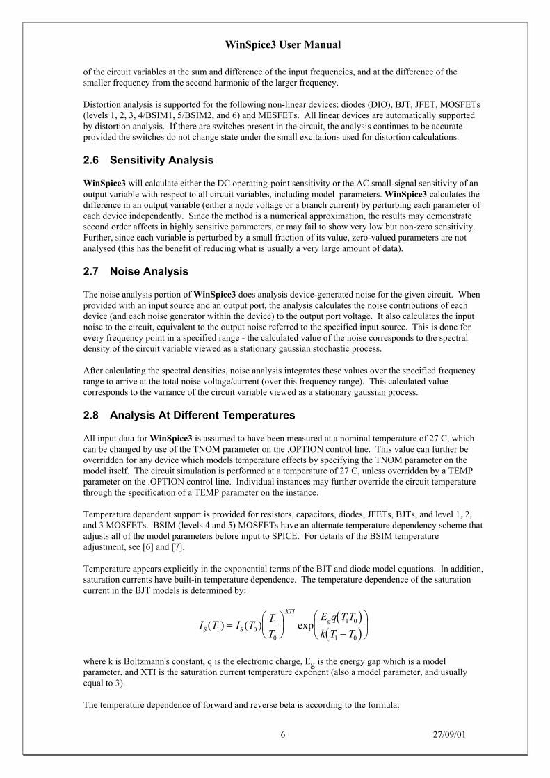
Temperature appears explicitly in the exponential terms of the BJT and diode model equations. In addition,saturation currents have built-in temperature dependence. The temperature dependence of the saturationcurrent in the BJT models is determined by:
( )( )
I T I TT
T
E q T T
k T TS S
XTI
g( ) ( ) exp1 01
0
1 0
1 0
=
−
where k is Boltzmann's constant, q is the electronic charge, Eg is the energy gap which is a modelparameter, and XTI is the saturation current temperature exponent (also a model parameter, and usuallyequal to 3).
The temperature dependence of forward and reverse beta is according to the formula:
WinSpice3 User Manual
7 27/09/01
( ) ( )β βT TT
T
XTB
1 01
0
=
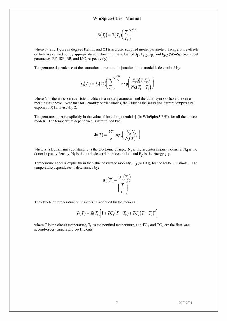
where T1 and T0 are in degrees Kelvin, and XTB is a user-supplied model parameter. Temperature effectson beta are carried out by appropriate adjustment to the values of βF, ISE, βR, and ISC (WinSpice3 modelparameters BF, ISE, BR, and ISC, respectively).
Temperature dependence of the saturation current in the junction diode model is determined by:
( ) ( ) ( )( )I T I T
T
T
E q T T
Nk T TS S
XTI
Ng
1 01
0
1 0
1 0
=
−
exp
where N is the emission coefficient, which is a model parameter, and the other symbols have the samemeaning as above. Note that for Schottky barrier diodes, the value of the saturation current temperatureexponent, XTI, is usually 2.
Temperature appears explicitly in the value of junction potential, φ (in WinSpice3 PHI), for all the devicemodels. The temperature dependence is determined by:
( )( )
Φ TkT
q
N N
N Tea d
i
=
log 2
where k is Boltzmann's constant, q is the electronic charge, Na is the acceptor impurity density, Nd is thedonor impurity density, Ni is the intrinsic carrier concentration, and Eg is the energy gap.
Temperature appears explicitly in the value of surface mobility, µ0 (or UO), for the MOSFET model. Thetemperature dependence is determined by:
( ) ( )5.1
0
000
=
T
T
TT
µµ
The effects of temperature on resistors is modelled by the formula:
( ) ( ) ( ) ( )[ ]R T R T TC T T TC T T= + − + −0 1 0 2 0
21
where T is the circuit temperature, T0 is the nominal temperature, and TC1 and TC2 are the first- andsecond-order temperature coefficients.
WinSpice3 User Manual
8 27/09/01
3 CIRCUIT DESCRIPTION
3.1 General Structure And Conventions
The circuit to be analysed is described to WinSpice3 by a set of element lines, which define the circuittopology and element values, and a set of control lines, which define the model parameters and the runcontrols. The first line in the input file must be the title, and the last line must be ".END". The order of theremaining lines is arbitrary (except, of course, that continuation lines must immediately follow the linebeing continued).
An element line that contains the element name, the circuit nodes to which the element is connected, andthe values of the parameters that determine the electrical characteristics of the element specify each elementin the circuit. The first letter of the element name specifies the element type. The format for the SPICEelement types is given in what follows. The strings XXXXXXX, YYYYYYY, and ZZZZZZZ denotearbitrary alphanumeric strings. For example, a resistor name must begin with the letter R and can containone or more characters. Hence, R, R1, RSE, ROUT, and R3AC2ZY are valid resistor names. Details ofeach type of device are supplied in a following section.
Fields on a line are separated by one or more blanks, a comma, an equal ('=') sign, or a left or rightparenthesis; extra spaces are ignored. A line may be continued by entering a '+' (plus) in column 1 of thefollowing line; WinSpice3 continues reading beginning with column 2.
A name field must begin with a letter (A through Z) and cannot contain any delimiters.
A number field may be an integer field (12, -44), a floating point field (3.14159), either an integer orfloating point number followed by an integer exponent (1e-14, 2.65e3), or either an integer or a floatingpoint number followed by one of the following scale factors:
T = 1012 G = 109 Meg = 106 K = 103 mil = 25.4-6
m = 10-3 u (or M) = 10-6 N = 10-9 p = 10-12 f = 10-15
Letters immediately following a number that are not scale factors are ignored, and letters immediatelyfollowing a scale factor are ignored. Hence, 10, 10V, 10Volts, and 10Hz all represent the same number,and M, MA, MSec, and MMhos all represent the same scale factor. Note that 1000, 1000.0, 1000Hz, 1e3,1.0e3, 1KHz, and 1K all represent the same number.
Nodes names may be arbitrary character strings. The datum (ground) node must be named '0'. Note thedifference in WinSpice3 where the nodes are treated as character strings and not evaluated as numbers,thus '0' and '00' are distinct nodes in WinSpice3 but not in SPICE2. The circuit cannot contain a loop ofvoltage sources and/or inductors and cannot contain a cut-set of current sources and/or capacitors.
Each node in the circuit must have a DC path to ground.
Every node must have at least two connections except for transmission line nodes (to permit unterminatedtransmission lines) and MOSFET substrate nodes (which have two internal connections anyway).
3.2 Title Line, Comment Lines And .END Line
3.2.1 Title Line
Examples:
POWER AMPLIFIER CIRCUITTEST OF CAM CELL
The title line must be the first in the input file. Its contents are printed verbatim as the heading for eachsection of output.

WinSpice3 User Manual
9 27/09/01
3.2.2 .END Line
Examples:
.END
The "End" line must always be the last in the input file. Note that the period is an integral part of the name.
3.2.3 Comments
General Form:
* <any comment>
Examples:
* RF=1K Gain should be 100* Check open-loop gain and phase margin
The asterisk in the first column indicates that this line is a comment line. Comment lines may be placedanywhere in the circuit description. Note that WinSpice3 also considers any line with leading white spaceto be a comment.
3.3 .MODEL: Device Models
General form:
.MODEL MNAME TYPE(PNAME1=PVAL1 PNAME2=PVAL2 ... )
Examples:
.MODEL MOD1 NPN (BF=50 IS=1E-13 VBF=50)
Most simple circuit elements typically require only a few parameter values. However, some devices(semiconductor devices in particular) that are included in WinSpice3 require many parameter values.Often, many devices in a circuit are defined by the same set of device model parameters. For these reasons,a set of device model parameters is defined on a separate .MODEL line and assigned a unique model name.The device element lines in WinSpice3 then refer to the model name.
For these more complex device types, each device element line contains the device name, the nodes towhich the device is connected, and the device model name. In addition, other optional parameters may bespecified for some devices: geometric factors and an initial condition (see the following section onTransistors and Diodes for more details).

WinSpice3 User Manual
10 27/09/01
MNAME in the above is the model name, and type is one of the following types:
R Semiconductor resistor model
C Semiconductor capacitor model
SWVSWITCH
Voltage controlled switch
CSWISWITCH
Current controlled switch
URC Uniform distributed RC model
LTRA Lossy transmission line model
D Diode model
NPN NPN BJT model
PNP PNP BJT model
NJF N-channel JFET model
PJF P-channel JFET model
NMOS N-channel MOSFET model
PMOS P-channel MOSFET model
NMF N-channel MESFET model
PMF P-channel MESFET model
Parameter values are defined by appending the parameter name followed by an equal sign and theparameter value. Model parameters that are not given a value are assigned the default values given belowfor each model type. Models, model parameters, and default values are listed in the next section along withthe description of device element lines.
3.4 Subcircuits
A subcircuit that consists of WinSpice3 elements can be defined and referenced in a fashion similar todevice models. The subcircuit is defined in the input file by a grouping of element lines; the program thenautomatically inserts the group of elements wherever the subcircuit is referenced. There is no limit on thesize or complexity of subcircuits, and subcircuits may contain other subcircuits. An example of subcircuitusage is given in Appendix A.
3.4.1 .SUBCKT Line
General form:
.SUBCKT subnam N1 <N2 N3 ...>
Examples:
.SUBCKT OPAMP 1 2 3 4
A circuit definition is begun with a .SUBCKT line. SUBNAM is the subcircuit name, and N1, N2, are theexternal nodes, which cannot be zero. The group of element lines which immediately follow the .SUBCKTline define the subcircuit. The last line in a subcircuit definition is the .ENDS line (see below). Control

WinSpice3 User Manual
11 27/09/01
lines may not appear within a subcircuit definition; however, subcircuit definitions may contain anythingelse, including other subcircuit definitions, device models, and subcircuit calls (see below). Note that anydevice models or subcircuit definitions included as part of a subcircuit definition are strictly local (i.e., suchmodels and definitions are not known outside the subcircuit definition). Also, any element nodes notincluded on the .SUBCKT line are strictly local, with the exception of 0 (ground) which is always global.
3.4.2 .ENDS Line
General form:
.ENDS <SUBNAM>
Examples:
.ENDS OPAMP
The "Ends" line must be the last one for any subcircuit definition. The subcircuit name, if included,indicates which subcircuit definition is being terminated; if omitted, all subcircuits being defined areterminated. The name is needed only when nested subcircuit definitions are being made.
3.4.3 Xxxxx: Subcircuit Calls
General form:
XYYYYYYY N1 <N2 N3 ...> SUBNAM
Examples:
X1 2 4 17 3 1 MULTI
Subcircuits are used in SPICE by specifying pseudo-elements beginning with the letter X, followed by thecircuit nodes to be used in expanding the subcircuit.
3.5 Combining Files
3.5.1 .INCLUDE Lines
General form:
.INCLUDE filename
Examples:
.INCLUDE /users/spice/common/wattmeter.cir
Frequently, portions of circuit descriptions will be reused in several input files, particularly with commonmodels and subcircuits. In any SPICE input file, the ".include" line may be used to copy some other file asif that second file appeared in place of the ".include" line in the original file. There is no restriction on thefile name imposed by SPICE beyond those imposed by the local operating system.
3.5.2 .LIB Lines
General form:
.LIB filename
Examples:
.LIB /users/spice/common/bipolar.lib
This is an extension, not found in the Berkeley version of SPICE3, that provides backward compatibilitywith PSPICE.
The .LIB line is similar to the .INCLUDE line except that the specified file is assumed to contain .MODELand .SUBCKT definitions. WinSpice3 searches for any undefined models or subcircuits in the specifiedfile and extracts the required definitions and pastes them into the circuit. The main difference is that

WinSpice3 User Manual
12 27/09/01
because it only extracts parts of the specified file and does not include the whole file in your circuit, the.LIB line uses far less memory.
The input file can have any extension, but by convention has the extension .lib.

WinSpice3 User Manual
13 27/09/01
4 CIRCUIT ELEMENTS AND MODELS
Data fields that are enclosed in less-than and greater-than signs ('< >') are optional. All indicatedpunctuation (parentheses, equal signs, etc.) is optional but indicate the presence of any delimiter. Further,future implementations may require the punctuation as stated. A consistent style adhering to thepunctuation shown here makes the input easier to understand. With respect to branch voltages andcurrents, WinSpice3 uniformly uses the associated reference convention (current flows in the direction ofvoltage drop).
4.1 Elementary Devices
4.1.1 Rxxxx: Resistors
4.1.1.1 Simple Resistors
General form:
RXXXXXXX N1 N2 VALUE
Examples:
R1 1 2 100RC1 12 17 1K
N1 and N2 are the two element nodes. VALUE is the resistance (in ohms) and may be positive or negativebut not zero.
Spice2 allows
4.1.1.2 Semiconductor Resistors
General form:
RXXXXXXX N1 N2 <VALUE> <MNAME> <L=LENGTH> <W=WIDTH> <TEMP=T>
Examples:
RLOAD 2 10 10KRMOD 3 7 RMODEL L=10u W=1u
This is the more general form of the resistor presented in section 4.1.1.1, and allows the modelling oftemperature effects and for the calculation of the actual resistance value from strictly geometric informationand the specifications of the process.
If VALUE is specified, it overrides the geometric information and defines the resistance. If MNAME isspecified, then the resistance may be calculated from the process information in the model MNAME andthe given LENGTH and WIDTH. If VALUE is not specified, then MNAME and LENGTH must bespecified. If WIDTH is not specified, then it is taken from the default width given in the model. The(optional) TEMP value is the temperature at which this device is to operate, and overrides the temperaturespecification on the .OPTION control line.
4.1.1.3 Semiconductor Resistor Model (R)
The resistor model consists of process-related device data that allow the resistance to be calculated fromgeometric information and to be corrected for temperature.

WinSpice3 User Manual
14 27/09/01
The parameters available are:
name parameter units default example
TC1 first order temperature coefficient Ω/°C 0.0 -
TC2 second order temperature coefficient. Ω/°C2 0.0 -
RSH sheet resistance Ω/square - 50
DEFW default width meters 1e-6 2e-6
NARROW narrowing due to side etching meters 0.0 1e-7
TNOM parameter measurement temperature °C 27 50
The sheet resistance is used with the narrowing parameter and L and W from the resistor device todetermine the nominal resistance by the formula
R RSHL NARROW
W NARROW=
−−
DEFW is used to supply a default value for W if one is not specified for the device. If either RSH or L isnot specified, then the standard default resistance value of 1k Z is used.
TNOM is used to override the circuit-wide value given on the .OPTIONS control line where the parametersof this model have been measured at a different temperature. After the nominal resistance is calculated, itis adjusted for temperature by the formula:
( ) ( ) ( ) ( )[ ]R T R T TC T T TC T T= + − + −0 1 0 2 0
21
4.1.2 Cxxxx: Capacitors
4.1.2.1 Simple Capacitors
General form:
CXXXXXXX N+ N- VALUE <IC=INCOND>
Examples:
CBYP 13 0 1UFCOSC 17 23 10U IC=3V
N+ and N- are the positive and negative element nodes, respectively. VALUE is the capacitance in Farads.
The (optional) initial condition is the initial (time- zero) value of capacitor voltage (in Volts). Note that theinitial conditions (if any) apply 'only' if the UIC option is specified on the .TRAN control line.
NOTE: unlike Spice2, non-linear capacitors using POLY are not directly supported by WinSpice3.However, they can be simulated using non-linear current and voltage sources. Voltage and temperaturedependent capacitance can be simulated using the capacitor model described in section 4.1.2.3.
WinSpice3 User Manual
15 27/09/01
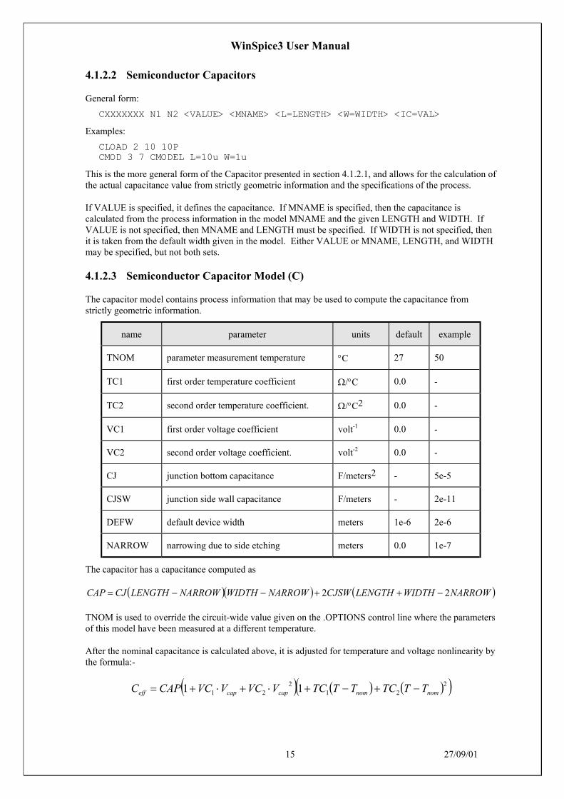
4.1.2.2 Semiconductor Capacitors
General form:
CXXXXXXX N1 N2 <VALUE> <MNAME> <L=LENGTH> <W=WIDTH> <IC=VAL>
Examples:
CLOAD 2 10 10PCMOD 3 7 CMODEL L=10u W=1u
This is the more general form of the Capacitor presented in section 4.1.2.1, and allows for the calculation ofthe actual capacitance value from strictly geometric information and the specifications of the process.
If VALUE is specified, it defines the capacitance. If MNAME is specified, then the capacitance iscalculated from the process information in the model MNAME and the given LENGTH and WIDTH. IfVALUE is not specified, then MNAME and LENGTH must be specified. If WIDTH is not specified, thenit is taken from the default width given in the model. Either VALUE or MNAME, LENGTH, and WIDTHmay be specified, but not both sets.
4.1.2.3 Semiconductor Capacitor Model (C)
The capacitor model contains process information that may be used to compute the capacitance fromstrictly geometric information.
name parameter units default example
TNOM parameter measurement temperature °C 27 50
TC1 first order temperature coefficient Ω/°C 0.0 -
TC2 second order temperature coefficient. Ω/°C2 0.0 -
VC1 first order voltage coefficient volt-1 0.0 -
VC2 second order voltage coefficient. volt-2 0.0 -
CJ junction bottom capacitance F/meters2 - 5e-5
CJSW junction side wall capacitance F/meters - 2e-11
DEFW default device width meters 1e-6 2e-6
NARROW narrowing due to side etching meters 0.0 1e-7
The capacitor has a capacitance computed as
( )( ) ( )NARROWWIDTHLENGTHCJSWNARROWWIDTHNARROWLENGTHCJCAP 22 −++−−=
TNOM is used to override the circuit-wide value given on the .OPTIONS control line where the parametersof this model have been measured at a different temperature.
After the nominal capacitance is calculated above, it is adjusted for temperature and voltage nonlinearity bythe formula:-
( ) ( ) ( )( )221
221 11 nomnomcapcapeff TTTCTTTCVVCVVCCAPC −+−+⋅+⋅+=

WinSpice3 User Manual
16 27/09/01
4.1.3 Lxxxx: Inductors
General form:
LYYYYYYY N+ N- VALUE <IC=INCOND>
Examples:
LLINK 42 69 1UHLSHUNT 23 51 10U IC=15.7MA
N+ and N- are the positive and negative element nodes, respectively. VALUE is the inductance in Henries.
The (optional) initial condition is the initial (time-zero) value of inductor current (in Amps) that flows fromN+, through the inductor, to N-. Note that the initial conditions (if any) apply only if the UIC option isspecified on the .TRAN analysis line.
NOTE: unlike Spice2, non-linear inductors are not directly supported by WinSpice3. However, they can besimulated using non-linear current and voltage sources.
4.1.4 Kxxxx: Coupled (Mutual) Inductors
General form:
KXXXXXXX LYYYYYYY LZZZZZZZ VALUE
Examples:
K43 LAA LBB 0.999KXFRMR L1 L2 0.87
LYYYYYYY and LZZZZZZZ are the names of the two coupled inductors, and VALUE is the coefficientof coupling, K, which must be greater than 0 and less than or equal to 1. Using the 'dot' convention, place a'dot' on the first node of each inductor.
4.1.5 Sxxxx and Wxxxx: Switches
4.1.5.1 Sxxxx: Voltage Controlled Switch
General form:
SXXXXXXX N+ N- NC+ NC- MODEL <ON><OFF>
Examples:
s1 1 2 3 4 switch1 ONs2 5 6 3 0 sm2 offSwitch1 1 2 10 0 smodel1
Nodes 1 and 2 are the nodes between which the switch terminals are connected. The model name ismandatory while the initial conditions are optional. Nodes 3 and 4 are the positive and negative controllingnodes respectively.
4.1.5.2 Wxxxx: Current Controlled Switch
General form:
WYYYYYYY N+ N- VNAM MODEL <ON><OFF>
Examples:
w1 1 2 vclock switchmod1W2 3 0 vramp sm1 ONwreset 5 6 vclck lossyswitch OFF

WinSpice3 User Manual
17 27/09/01
Nodes 1 and 2 are the nodes between which the switch terminals are connected. The model name ismandatory while the initial conditions are optional. The controlling current is that through the specifiedvoltage source. The direction of positive controlling current flow is from the positive node, through thesource, to the negative node.
4.1.5.3 Switch Model (SW/CSW)
General form:
.MODEL MNAME TYPE(PNAME1=PVAL1 PNAME2=PVAL2 ... )
Examples:
.MODEL SMOD SW(RON=5M ROFF=10E9 VT=1.0 VH=0.1)
.MODEL SMOD VSWITCH(RON=5M ROFF=10E9 VON=1.1 VOFF=0.9)
.MODEL SMOD CSW(RON=5M ROFF=10E9 IT=0.5MA IH=0.5MA)
.MODEL SMOD ISWITCH(RON=5M ROFF=10E9 ION=1.0MA IOFF=0)
The VSWITCH and ISWITCH forms of the model show above are provided for compatibility withPSPICE.
The switch model allows an almost ideal switch to be described in WinSpice3. The switch is not quiteideal, in that the resistance can not change from 0 to infinity, but must always have a finite positive value.By proper selection of the on and off resistances, they can be effectively zero and infinity in comparison toother circuit elements.
The parameters available are:
name parameter units default switch
VT threshold voltage Volts 0.0 S
VH hysteresis voltage Volts 0.0 S
VON threshold voltage Volts 0.0 S
VOFF threshold voltage Volts 0.0 S
IT threshold current Amps 0.0 W
IH hysteresis current Amps 0.0 W
ION threshold current Amps 0.0 W
IOFF threshold current Amps 0.0 W
RON on resistance Ω 1.0 both
ROFF off resistance Ω 1/GMIN*
both
*(See the .OPTIONS control line for a description of GMIN, its default value results in an off-resistance of1.0e+12 ohms.)
For the voltage controlled switch, the switch is in the ON state if
)( VHVTVctrl +>
if VT and VH are defined or

WinSpice3 User Manual
18 27/09/01
)(VONVctrl >
if VON is defined. It is in the OFF state if
)( VHVTVctrl −<
if VT and VH are defined or
)(VOFFVctrl <
if VOFF is defined.
For the current controlled switch, the switch is in the ON state if
)( IHITIctrl +>
if IT and IH are defined or
)(IONIctrl >
if ION is defined.
and is in the OFF state if
)( IHITIctrl −<
if IT and IH are defined or
)(IOFFIctrl <
if IOFF is defined.
The use of an ideal element that is highly non-linear such as a switch can cause large discontinuities tooccur in the circuit node voltages. A rapid change such as that associated with a switch changing state cancause numerical roundoff or tolerance problems leading to erroneous results or timestep difficulties. Theuser of switches can improve the situation by taking the following steps:
First, it is wise to set ideal switch impedances just high or low enough to be negligible with respect to othercircuit elements. Using switch impedances that are close to "ideal" in all cases aggravates the problem ofdiscontinuities mentioned above. Of course, when modelling real devices such as MOSFETs, the onresistance should be adjusted to a realistic level depending on the size of the device being modelled.
If a wide range of ON to OFF resistance must be used in the switches (ROFF/RON > 1e+12), then thetolerance on errors allowed during transient analysis should be decreased by using the .OPTIONS controlline and specifying TRTOL to be less than the default value of 7.0. When switches are placed aroundcapacitors, then the option CHGTOL should also be reduced. Suggested values for these two options are1.0 and 1e-16 respectively. These changes inform WinSpice3 to be more careful around the switch pointsso that no errors are made due to the rapid change in the circuit.

WinSpice3 User Manual
19 27/09/01
4.2 Voltage And Current Sources
4.2.1 Ixxxx and Vxxxx: Independent Sources
General form:
VXXXXXXX N+ N- <<DC> DC/TRAN VALUE> <AC <ACMAG <ACPHASE>>>+ <DISTOF1 <F1MAG <F1PHASE>>> <DISTOF2 <F2MAG <F2PHASE>>>IYYYYYYY N+ N- <<DC> DC/TRAN VALUE> <AC <ACMAG <ACPHASE>>>+ <DISTOF1 <F1MAG <F1PHASE>>> <DISTOF2 <F2MAG <F2PHASE>>>
Examples:
VCC 10 0 DC 6VIN 13 2 0.001 AC 1 SIN(0 1 1MEG)ISRC 23 21 AC 0.333 45.0 SFFM(0 1 10K 5 1K)VMEAS 12 9VCARRIER 1 0 DISTOF1 0.1 -90.0VMODULATOR 2 0 DISTOF2 0.01IIN1 1 5 AC 1 DISTOF1 DISTOF2 0.001
N+ and N- are the positive and negative nodes, respectively. Note that voltage sources need not begrounded. Positive current is assumed to flow from the positive node, through the source, to the negativenode. A current source of positive value forces current to flow out of the N+ node, through the source, andinto the N- node. Voltage sources, in addition to being used for circuit excitation, are the 'ammeters' forWinSpice3, that is, zero valued voltage sources may be inserted into the circuit for the purpose ofmeasuring current. They of course have no effect on circuit operation since they represent short-circuits.
DC/TRAN is the DC and transient analysis value of the source. If the source value is zero both for DCand transient analyses, this value may be omitted. If the source value is time-invariant (e.g., a powersupply), then the value may optionally be preceded by the letters DC.
ACMAG is the AC magnitude and ACPHASE is the AC phase. The source is set to this value in the ACanalysis. If ACMAG is omitted following the keyword AC, a value of unity is assumed. If ACPHASE isomitted, a value of zero is assumed. If the source is not an AC small-signal input, the keyword AC and theAC values are omitted.
DISTOF1 and DISTOF2 are the keywords that specify that the independent source has distortion inputs atthe frequencies F1 and F2 respectively (see the description of the .DISTO control line). An optionalmagnitude and phase may follow the keywords. The default values of the magnitude and phase are 1.0 and0.0 respectively.
Any independent source can be assigned a time-dependent value for transient analysis. If a source isassigned a time-dependent value, the time-zero value is used for DC analysis. There are five independentsource functions: pulse, exponential, sinusoidal, piece-wise linear, and single-frequency FM. If parametersother than source values are omitted or set to zero, the default values shown are assumed. (TSTEP is theprinting increment and TSTOP is the final time (see the .TRAN control line for explanation)).
4.2.1.1 PULSE(): Pulse
General form:
PULSE(V1 V2 TD TR TF PW PER)
Examples:
VIN 3 0 PULSE(-1 1 2NS 2NS 2NS 50NS 100NS)

WinSpice3 User Manual
20 27/09/01
parameter default value units
V1 (initial value) Volts or Amps
V2 (pulsed value) Volts or Amps
TD (delay time) 0.0 seconds
TR (rise time) TSTEP seconds
TF (fall time) TSTEP seconds
PW (pulse width) TSTOP seconds
PER(period) TSTOP seconds
The following table describes a single pulse so specified:
Time value
0 V1
TD V1
TD+TR V2
TD+TR+PW V2
TD+TR+PW+TF V1
TSTOP V1
Intermediate points are determined by linear interpolation.
4.2.1.2 SIN(): Sinusoidal
General form:
SIN(VO VA FREQ TD THETA)
Examples:
VIN 3 0 SIN(0 1 100MEG 1NS 1E10)
parameters default value units
VO (offset) Volts or Amps
VA (amplitude) Volts or Amps
FREQ (frequency) 1/TSTOP Hz
TD (delay) 0.0 seconds
THETA (damping factor) 0.0 1/seconds

WinSpice3 User Manual
21 27/09/01
The following table describes the shape of the waveform:
time value
0 to TD VO
TD to TSTOP ( ) ( )( )VO VAe FREQ t TDt TD THETA+ +− − sin 2π
4.2.1.3 EXP(): Exponential
General Form:
EXP(V1 V2 TD1 TAU1 TD2 TAU2)
Examples:
VIN 3 0 EXP(-4 -1 2NS 30NS 60NS 40NS)
parameter default value units
V1 (initial value) Volts or Amps
V2 (pulsed value) Volts or Amps
TD1 (rise delay time) 0.0 seconds
TAU1 (rise time constant) TSTEP seconds
TD2 (fall delay time) TD1+TSTEP seconds
TAU2 (fall time constant) TSTEP seconds
The following table describes the shape of the waveform:
time value
0 to TD1 V1
TD1 to TD2
( )( )
V V V et TD
TAU1 2 1 11
1+ − −
− −
TD2 to TSTOP
( )( )
( )( )
V V V e V V et TD
TAU
t TD
TAU1 2 1 1 2 11
1
2
2+ − −
+ − −
− − − −
4.2.1.4 PWL(): Piece-Wise Linear
General Form:
PWL(T1 V1 <T2 V2 T3 V3 T4 V4 ...>)
Examples:
VCLOCK 7 5 PWL(0 -7 10NS -7 11NS -3 17NS -3 18NS -7 50NS -7)
WinSpice3 User Manual
22 27/09/01
Each pair of values (Ti, Vi) specifies that the value of the source is Vi (in Volts or Amps) at time=Ti. Thevalue of the source at intermediate values of time is determined by using linear interpolation on the inputvalues.
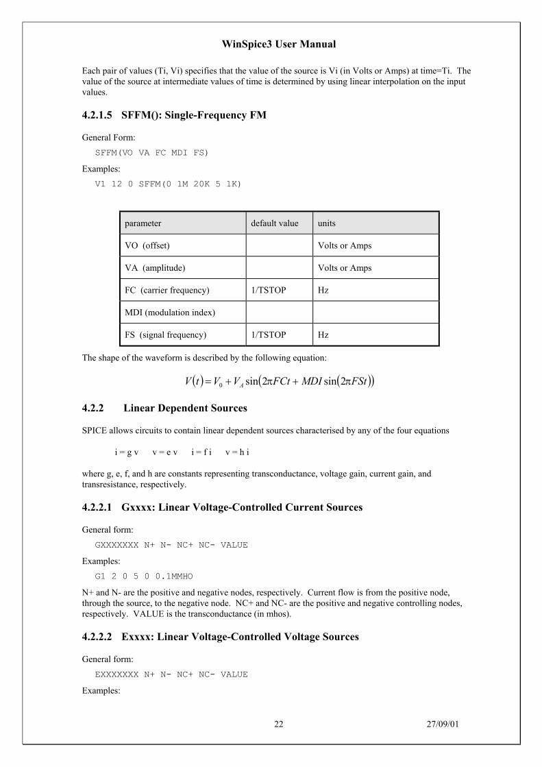
4.2.1.5 SFFM(): Single-Frequency FM
General Form:
SFFM(VO VA FC MDI FS)
Examples:
V1 12 0 SFFM(0 1M 20K 5 1K)
parameter default value units
VO (offset) Volts or Amps
VA (amplitude) Volts or Amps
FC (carrier frequency) 1/TSTOP Hz
MDI (modulation index)
FS (signal frequency) 1/TSTOP Hz
The shape of the waveform is described by the following equation:
( ) ( )( )FStMDIFCtVVtV A ππ 2sin2sin0 ++=
4.2.2 Linear Dependent Sources
SPICE allows circuits to contain linear dependent sources characterised by any of the four equations
i = g v v = e v i = f i v = h i
where g, e, f, and h are constants representing transconductance, voltage gain, current gain, andtransresistance, respectively.
4.2.2.1 Gxxxx: Linear Voltage-Controlled Current Sources
General form:
GXXXXXXX N+ N- NC+ NC- VALUE
Examples:
G1 2 0 5 0 0.1MMHO
N+ and N- are the positive and negative nodes, respectively. Current flow is from the positive node,through the source, to the negative node. NC+ and NC- are the positive and negative controlling nodes,respectively. VALUE is the transconductance (in mhos).
4.2.2.2 Exxxx: Linear Voltage-Controlled Voltage Sources
General form:
EXXXXXXX N+ N- NC+ NC- VALUE
Examples:

WinSpice3 User Manual
23 27/09/01
E1 2 3 14 1 2.0
N+ is the positive node, and N- is the negative node. NC+ and NC- are the positive and negativecontrolling nodes, respectively. VALUE is the voltage gain.
4.2.2.3 Fxxxx: Linear Current-Controlled Current Sources
General form:
FXXXXXXX N+ N- VNAM VALUE
Examples:
F1 13 5 VSENS 5
N+ and N- are the positive and negative nodes, respectively. Current flow is from the positive node,through the source, to the negative node. VNAM is the name of a voltage source through which thecontrolling current flows. The direction of positive controlling current flow is from the positive node,through the source, to the negative node of VNAM. VALUE is the current gain.
4.2.2.4 Hxxxx: Linear Current-Controlled Voltage Sources
General form:
HXXXXXXX N+ N- VNAM VALUE
Examples:
HX 5 17 VZ 0.5K
N+ and N- are the positive and negative nodes, respectively. VNAM is the name of a voltage sourcethrough which the controlling current flows. The direction of positive controlling current flow is from thepositive node, through the source, to the negative node of VNAM. VALUE is the transresistance (inohms).
4.2.3 Non-linear Dependent Sources using POLY()
For compatibility with SPICE2, WinSpice allows circuits to contain dependent sources characterised byany of the four equations
i=f(v) v=f(v) i=f(i) v=f(i)
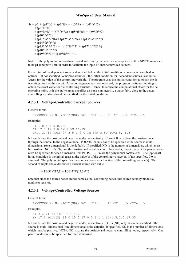
where the functions must be polynomials, and the arguments may be multidimensional. The polynomialfunctions are specified by a set of coefficients p0, p1, ..., pn. Both the number of dimensions and thenumber of coefficients are arbitrary. The meaning of the coefficients depends upon the dimension of thepolynomial, as shown in the following examples:
Suppose that the function is one-dimensional (that is, a function of one argument). Then the functionvalue fv is determined by the following expression in fa (the function argument):
fv = p0 + (p1*fa) + (p2*fa**2) + (p3*fa**3) + (p4*fa**4) + (p5*fa**5) + ...
Suppose now that the function is two-dimensional, with arguments fa and fb. Then the function value fv isdetermined by the following expression:
fv = p0 + (p1*fa) + (p2*fb) + (p3*fa**2) + (p4*fa*fb) + (p5*fb**2) + (p6*fa**3) + (p7*fa**2*fb) + (p8*fa*fb**2) + (p9*fb**3) + ...
Consider now the case of a three-dimensional polynomial function with arguments fa, fb, and fc. Then thefunction value fv is determined by the following expression:
WinSpice3 User Manual
24 27/09/01
fv = p0 + (p1*fa) + (p2*fb) + (p3*fc) + (p4*fa**2) + (p5*fa*fb) + (p6*fa*fc) + (p7*fb**2) + (p8*fb*fc) + (p9*fc**2) + (p10*fa**3) + (p11*fa**2*fb) + (p12*fa**2*fc) + (p13*fa*fb**2) + (p14*fa*fb*fc) + (p15*fa*fc**2) + (p16*fb**3) + (p17*fb**2*fc) + (p18*fb*fc**2) + (p19*fc**3) + (p20*fa**4) + ...
Note: if the polynomial is one-dimensional and exactly one coefficient is specified, then SPICE assumes itto be p1 (and p0 = 0.0), in order to facilitate the input of linear controlled sources.
For all four of the dependent sources described below, the initial condition parameter is described asoptional. If not specified, WinSpice assumes 0 the initial condition for dependent sources is an initial'guess' for the value of the controlling variable. The program uses this initial condition to obtain the dcoperating point of the circuit. After convergence has been obtained, the program continues iterating toobtain the exact value for the controlling variable. Hence, to reduce the computational effort for the dcoperating point, or if the polynomial specifies a strong nonlinearity, a value fairly close to the actualcontrolling variable should be specified for the initial condition.
4.2.3.1 Voltage-Controlled Current Sources
General form:
GXXXXXXX N+ N- <POLY(ND)> NC1+ NC1- ... P0 <P1 ...> <IC=...>
Examples:
G1 1 0 5 3 0 0.1MGR 17 3 17 3 0 1M 1.5M IC=2VGMLT 23 17 POLY(2) 3 5 1 2 0 1M 17M 3.5U IC=2.5, 1.3
N+ and N- are the positive and negative nodes, respectively. Current flow is from the positive node,through the source, to the negative node. POLY(ND) only has to be specified if the source is multi-dimensional (one-dimensional is the default). If specified, ND is the number of dimensions, which mustbe positive. NC1+, NC1-, .are the positive and negative controlling nodes, respectively. One pair of nodesmust be specified for each dimension. P0, P1, P2, ..., Pn are the polynomial coefficients. The (optional)initial condition is the initial guess at the value(s) of the controlling voltage(s). If not specified, 0.0 isassumed. The polynomial specifies the source current as a function of the controlling voltage(s). Thesecond example above describes a current source with value
I = 1E-3*V(17,3) + 1.5E-3*V(17,3)**2
note that since the source nodes are the same as the controlling nodes, this source actually models anonlinear resistor.
4.2.3.2 Voltage-Controlled Voltage Sources
General form:
EXXXXXXX N+ N- <POLY(ND)> NC1+ NC1- ... P0 <P1 ...> <IC=...>
Examples:
E1 3 4 21 17 10.5 2.1 1.75EX 17 0 POLY(3) 13 0 15 0 17 0 0 1 1 1 IC=1.5,2.0,17.35
N+ and N- are the positive and negative nodes, respectively. POLY(ND) only has to be specified if thesource is multi-dimensional (one-dimensional is the default). If specified, ND is the number of dimensions,which must be positive. NC1+, NC1-, ... are the positive and negative controlling nodes, respectively. Onepair of nodes must be specified for each dimension.

WinSpice3 User Manual
25 27/09/01
P0, P1, P2, ..., Pn are the polynomial coefficients. The optional initial condition is the initial guess atthe value(s) of the controlling voltage(s). If not specified, 0.0 is assumed.
The polynomial specifies the source voltage as a function of the controlling voltage(s). The secondexample above describes a voltage source with value
V = V(13,0) + V(15,0) + V(17,0)
(in other words, an ideal voltage summer).
4.2.3.3 Current-Controlled Current Sources
General form:
FXXXXXXX N+ N- <POLY(ND)> VN1 <VN2 ...> P0 <P1 ...> <IC=...>
Examples:
F1 12 10 VCC 1MA 1.3MFXFER 13 20 VSENS 0 1
N+ and N- are the positive and negative nodes, respectively. Current flow is from the positive node,through the source, to the negative node. POLY(ND) only has to be specified if the source is multi-dimensional (one-dimensional is the default). If specified, ND is the number of dimensions, which must bepositive. VN1, VN2, ... are the names of voltage sources through which the controlling current flows; onename must be specified for each dimension. The direction of positive controlling current flow is from thepositive node, through the source, to the negative node of each voltage source. P0, P1, P2, ..., Pn are thepolynomial coefficients. The (optional) initial condition is the initial guess at the value(s) of the controllingcurrent(s) (in Amps). If not specified, 0.0 is assumed. The polynomial specifies the source current as afunction of the controlling current(s). The first example above describes a current source with value
I = 1E-3 + 1.3E-3*I(VCC)
4.2.3.4 Current-Controlled Voltage Sources
General form:
HXXXXXXX N+ N- <POLY(ND)> VN1 <VN2 ...> P0 <P1 ...> <IC=...>
Examples:
HXY 13 20 POLY(2) VIN1 VIN2 0 0 0 0 1 IC=0.5 1.3HR 4 17 VX 0 0 1
N+ and N- are the positive and negative nodes, respectively. POLY(ND) only has to be specified if thesource is multi-dimensional (one-dimensional is the default). If specified, ND is the number of dimensions,which must be positive. VN1, VN2, ... are the names of voltage sources through which the controllingcurrent flows; one name must be specified for each dimension. The direction of positive controlling currentflow is from the positive node, through the source, to the negative node of each voltage source. P0, P1, P2,..., Pn are the polynomial coefficients. The optional initial condition is the initial guess at the value(s) ofthe controlling current(s) (in Amps). If not specified, 0.0 is assumed. The polynomial specifies the sourcevoltage as a function of the controlling current(s). The first example above describes a voltage source withvalue
V = I(VIN1)*I(VIN2)
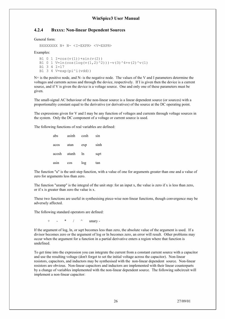
WinSpice3 User Manual
26 27/09/01
4.2.4 Bxxxx: Non-linear Dependent Sources
General form:
BXXXXXXX N+ N- <I=EXPR> <V=EXPR>
Examples:
B1 0 1 I=cos(v(1))+sin(v(2))B1 0 1 V=ln(cos(log(v(1,2)^2)))-v(3)^4+v(2)^v(1)B1 3 4 I=17B1 3 4 V=exp(pi^i(vdd))
N+ is the positive node, and N- is the negative node. The values of the V and I parameters determine thevoltages and currents across and through the device, respectively. If I is given then the device is a currentsource, and if V is given the device is a voltage source. One and only one of these parameters must begiven.
The small-signal AC behaviour of the non-linear source is a linear dependent source (or sources) with aproportionality constant equal to the derivative (or derivatives) of the source at the DC operating point.
The expressions given for V and I may be any function of voltages and currents through voltage sources inthe system. Only the DC component of a voltage or current source is used.
The following functions of real variables are defined:
abs asinh cosh sin
acos atan exp sinh
acosh atanh ln sqrt
asin cos log tan
The function "u" is the unit step function, with a value of one for arguments greater than one and a value ofzero for arguments less than zero.
The function "uramp" is the integral of the unit step: for an input x, the value is zero if x is less than zero,or if x is greater than zero the value is x.
These two functions are useful in synthesising piece-wise non-linear functions, though convergence may beadversely affected.
The following standard operators are defined:
+ - * / ^ unary -
If the argument of log, ln, or sqrt becomes less than zero, the absolute value of the argument is used. If adivisor becomes zero or the argument of log or ln becomes zero, an error will result. Other problems mayoccur when the argument for a function in a partial derivative enters a region where that function isundefined.
To get time into the expression you can integrate the current from a constant current source with a capacitorand use the resulting voltage (don't forget to set the initial voltage across the capacitor). Non-linearresistors, capacitors, and inductors may be synthesised with the non-linear dependent source. Non-linearresistors are obvious. Non-linear capacitors and inductors are implemented with their linear counterpartsby a change of variables implemented with the non-linear dependent source. The following subcircuit willimplement a non-linear capacitor:

WinSpice3 User Manual
27 27/09/01
.Subckt nlcap pos neg* Bx: calculate f(input voltage)Bx 1 0 v = f(v(pos,neg))* Cx: linear capacitanceCx 2 0 1* Vx: Ammeter to measure current into the capacitorVx 2 1 DC 0Volts* Drive the current through Cx back into the circuitFx pos neg Vx 1.ends
Non-linear inductors are similar.
4.3 Transmission Lines
4.3.1 Txxxx: Lossless Transmission Lines
General form:
TXXXXXXX N1 N2 N3 N4 Z0=VALUE <TD=VALUE> <F=FREQ <NL=NRMLEN>>+ <IC=V1, I1, V2, I2>
Examples:
T1 1 0 2 0 Z0=50 TD=10NS
N1 and N2 are the nodes at port 1; N3 and N4 are the nodes at port 2. Z0 is the characteristic impedance.The length of the line may be expressed in either of two forms. The transmission delay, TD, may bespecified directly (as TD=10ns, for example). Alternatively, a frequency F may be given, together withNL, the normalised electrical length of the transmission line with respect to the wavelength in the line at thefrequency F. If a frequency is specified but NL is omitted, 0.25 is assumed (that is, the frequency isassumed to be the quarter-wave frequency). Note that although both forms for expressing the line lengthare indicated as optional, one of the two must be specified.
Note that this element models only one propagating mode. If all four nodes are distinct in the actual circuit,then two modes may be excited. To simulate such a situation, two transmission-line elements are required(see the example in Appendix A for further clarification).
The (optional) initial condition specification consists of the voltage and current at each of the transmissionline ports. Note that the initial conditions (if any) apply 'only' if the UIC option is specified on the .TRANcontrol line.
Note that a lossy transmission line (see below) with zero loss may be more accurate than the losslesstransmission line due to implementation details.
4.3.2 Oxxxx: Lossy Transmission Lines
General form:
OXXXXXXX N1 N2 N3 N4 MNAME
Examples:
O23 1 0 2 0 LOSSYMODOCONNECT 10 5 20 5 INTERCONNECT
This is a two-port convolution model for single-conductor lossy transmission lines. N1 and N2 are thenodes at port 1; N3 and N4 are the nodes at port 2. Note that a lossy transmission line with zero loss maybe more accurate than the lossless transmission line due to implementation details.
4.3.2.1 Lossy Transmission Line Model (LTRA)
The uniform RLC/RC/LC/RG transmission line model (referred to as the LTRA model henceforth)models a uniform constant-parameter distributed transmission line. The RC and LC cases may also be

WinSpice3 User Manual
28 27/09/01
modelled using the URC and TRA models; however, the newer LTRA model is usually faster and moreaccurate than the others are. The operation of the LTRA model is based on the convolution of thetransmission line's impulse responses with its inputs (see [8]).
The LTRA model takes a number of parameters, some of which must be given and others that are optional.
name parameter units/type default example
R resistance/length Z/unit 0.0 0.2
L inductance/length henrys/unit 0.0 9.13e-9
G conductance/length mhos/unit 0.0 0.0
C capacitance/length farads/unit 0.0 3.65e-12
LEN length of line no default 1.0
REL breakpoint control arbitrary unit 1 0.5
ABS breakpoint control 1 5
NOSTEPLIMIT don't limit timestep to lessthan line delay
flag not set set
NOCONTROL don't do complex timestepcontrol
flag not set set
LININTERP use linear interpolation flag not set set
MIXEDINTERP use linear when quadraticseems bad
not set set
COMPACTREL special reltol for historycompaction
flag RELTOL 1.0e-3
COMPACTABS special abstol for historycompaction
ABSTOL 1.0e-9
TRUNCNR use Newton-Raphson methodfor timestep control
flag not set set
TRUNCDONTCUT don't limit timestep to keepimpulse-response errors low
flag not set set
The following types of lines have been implemented so far: RLC (uniform transmission line with series lossonly), RC (uniform RC line), LC (lossless transmission line), and RG (distributed series resistance andparallel conductance only). Any other combination will yield erroneous results and should not be tried.The length LEN of the line must be specified.
NOSTEPLIMIT is a flag that will remove the default restriction of limiting time-steps to less than the linedelay in the RLC case. NOCONTROL is a flag that prevents the default limiting of the time-step based onconvolution error criteria in the RLC and RC cases. This speeds up simulation but may in some casesreduce the accuracy of results.
LININTERP is a flag that, when specified, will use linear interpolation instead of the default quadraticinterpolation for calculating delayed signals.
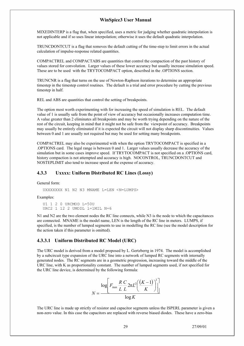
WinSpice3 User Manual
29 27/09/01
MIXEDINTERP is a flag that, when specified, uses a metric for judging whether quadratic interpolation isnot applicable and if so uses linear interpolation; otherwise it uses the default quadratic interpolation.
TRUNCDONTCUT is a flag that removes the default cutting of the time-step to limit errors in the actualcalculation of impulse-response related quantities.
COMPACTREL and COMPACTABS are quantities that control the compaction of the past history ofvalues stored for convolution. Larger values of these lower accuracy but usually increase simulation speed.These are to be used with the TRYTOCOMPACT option, described in the .OPTIONS section.
TRUNCNR is a flag that turns on the use of Newton-Raphson iterations to determine an appropriatetimestep in the timestep control routines. The default is a trial and error procedure by cutting the previoustimestep in half.
REL and ABS are quantities that control the setting of breakpoints.
The option most worth experimenting with for increasing the speed of simulation is REL. The defaultvalue of 1 is usually safe from the point of view of accuracy but occasionally increases computation time.A value greater than 2 eliminates all breakpoints and may be worth trying depending on the nature of therest of the circuit, keeping in mind that it might not be safe from the viewpoint of accuracy. Breakpointsmay usually be entirely eliminated if it is expected the circuit will not display sharp discontinuities. Valuesbetween 0 and 1 are usually not required but may be used for setting many breakpoints.
COMPACTREL may also be experimented with when the option TRYTOCOMPACT is specified in a.OPTIONS card. The legal range is between 0 and 1. Larger values usually decrease the accuracy of thesimulation but in some cases improve speed. If TRYTOCOMPACT is not specified on a .OPTIONS card,history compaction is not attempted and accuracy is high. NOCONTROL, TRUNCDONTCUT andNOSTEPLIMIT also tend to increase speed at the expense of accuracy.
4.3.3 Uxxxx: Uniform Distributed RC Lines (Lossy)
General form:
UXXXXXXX N1 N2 N3 MNAME L=LEN <N=LUMPS>
Examples:
U1 1 2 0 URCMOD L=50UURC2 1 12 2 UMODL l=1MIL N=6
N1 and N2 are the two element nodes the RC line connects, while N3 is the node to which the capacitancesare connected. MNAME is the model name, LEN is the length of the RC line in meters. LUMPS, ifspecified, is the number of lumped segments to use in modelling the RC line (see the model description forthe action taken if this parameter is omitted).
4.3.3.1 Uniform Distributed RC Model (URC)
The URC model is derived from a model proposed by L. Gertzberrg in 1974. The model is accomplishedby a subcircuit type expansion of the URC line into a network of lumped RC segments with internallygenerated nodes. The RC segments are in a geometric progression, increasing toward the middle of theURC line, with K as proportionality constant. The number of lumped segments used, if not specified forthe URC line device, is determined by the following formula:
( )
K
K
KL
L
C
L
RF
Nlog
12log
22
max
−
=
π
The URC line is made up strictly of resistor and capacitor segments unless the ISPERL parameter is given anon-zero value. In this case the capacitors are replaced with reverse biased diodes. These have a zero-bias

WinSpice3 User Manual
30 27/09/01
junction capacitance equivalent to the capacitance replaced, and with a saturation current of ISPERL ampsper meter of transmission line, and an optional series resistance equivalent to RSPERL ohms per meter.
name parameter units default example area
K Propagation Constant - 2.0 1.2 -
FMAX Maximum Frequency of interest Hz 1.0G 6.5Meg -
RPERL Resistance per unit length Ω/m 1000 10 -
CPERL Capacitance per unit length F/m 1.0e-15 1pF -
ISPERL Saturation Current per unit length A/m 0 - -
RSPERL Diode Resistance per unit length Ω/m 0 - -
4.4 Transistors And Diodes
WinSpice3 has built-in models for the semiconductor devices, and the user need specify only the pertinentmodel parameter values.
The model for the BJT is based on the integral-charge model of Gummel and Poon; however, if theGummel-Poon parameters are not specified, the model reduces to the simpler Ebers-Moll model. In eithercase, charge-storage effects, ohmic resistances, and a current-dependent output conductance may beincluded.
The diode model can be used for either junction diodes or Schottky barrier diodes. The JFET model isbased on the FET model of Shichman and Hodges.
Six MOSFET models are implemented: MOS1 is described by a square-law I-V characteristic, MOS2 [1] isan analytical model, while MOS3 [1] is a semi-empirical model; MOS6 [2] is a simple analytic modelaccurate in the short-channel region; MOS4 [3, 4] and MOS5 [5] are the BSIM (Berkeley Short-channelIGFET Model) and BSIM2. MOS2, MOS3, and MOS4 include second-order effects such as channel-length modulation, sub threshold conduction, scattering-limited velocity saturation, small-size effects, andcharge-controlled capacitances.
The area factor used on the diode, BJT, JFET, and MESFET devices determines the number of equivalentparallel devices of a specified model. The affected parameters are marked with an asterisk under theheading 'area' in the model descriptions below. Several geometric factors associated with the channel andthe drain and source diffusions can be specified on the MOSFET device line.
Two different forms of initial conditions may be specified for some devices. The first form is included toimprove the DC convergence for circuits that contain more than one stable state. If a device is specifiedOFF, the DC operating point is determined with the terminal voltages for that device set to zero. Afterconvergence is obtained, the program continues to iterate to obtain the exact value for the terminal voltages.If a circuit has more than one DC stable state, the OFF option can be used to force the solution tocorrespond to a desired state. If a device is specified OFF when in reality the device is conducting, theprogram still obtains the correct solution (assuming the solutions converge) but more iterations are requiredsince the program must independently converge to two separate solutions. The .NODESET control lineserves a similar purpose as the OFF option. The .NODESET option is easier to apply and is the preferredmeans to aid convergence.
The second form of initial conditions is specified for use with the transient analysis. These are true 'initialconditions' as opposed to the convergence aids above. See the description of the .IC control line and the.TRAN control line for a detailed explanation of initial conditions.

WinSpice3 User Manual
31 27/09/01
4.4.1 Dxxxx: Junction Diodes
General form:
DXXXXXXX N+ N- MNAME <AREA> <OFF> <IC=VD> <TEMP=T>
Examples:
DBRIDGE 2 10 DIODE1DCLMP 3 7 DMOD 3.0 IC=0.2
N+ and N- are the positive and negative nodes, respectively.
MNAME is the model name, AREA is the area factor, and OFF indicates an (optional) starting conditionon the device for DC analysis. If the area factor is omitted, a value of 1.0 is assumed.
The (optional) initial condition specification using IC=VD is intended for use with the UIC option on the.TRAN control line, when a transient analysis is desired starting from other than the quiescent operatingpoint.
The (optional) TEMP value is the temperature at which this device is to operate, and overrides thetemperature specification on the .OPTION control line.
4.4.1.1 Diode Model (D)
The DC characteristics of the diode are determined by the parameters IS and N. An ohmic resistance, RS,is included.
Charge storage effects are modelled by a transit time, TT, and a non-linear depletion layer capacitancewhich is determined by the parameters CJO, VJ, and M.
The temperature dependence of the saturation current is defined by the parameters EG, the energy andXTI, the saturation current temperature exponent. The nominal temperature at which these parameterswere measured is TNOM, which defaults to the circuit-wide value specified on the .OPTIONS control line.
Reverse breakdown is modelled by an exponential increase in the reverse diode current and is determinedby the parameters BV and IBV (both of which are positive numbers).

WinSpice3 User Manual
32 27/09/01
name parameter units default example area
IS saturation current A 1.0e-14 1.0e-14 *
RS ohmic resistance Ω 0 10 *
N emission coefficient - 1 1.0
TT transit-time sec 0 0.1ns
CJO zero-bias junction capacitance F 0 2pF *
VJ junction potential V 1 0.6
M grading coefficient - 0.5 0.5
EG activation energy eV 1.11 1.11 Si0.69 Sbd0.67 Ge
XTI saturation-current temp. exp - 3.0 3.0 jn2.0 Sbd
KF flicker noise coefficient - 0
AF flicker noise exponent - 1
FC coefficient for forward-bias depletioncapacitance formula
- 0.5
BV reverse breakdown voltage V infinite 40.0
IBV current at breakdown voltage A 1.0e-3
TNOM parameter measurement temperature °C 27 50
4.4.2 Qxxxx: Bipolar Junction Transistors (BJTs)
General form:
QXXXXXXX NC NB NE <NS> MNAME <AREA> <OFF> <IC=VBE, VCE> <TEMP=T>
Examples:
Q23 10 24 13 QMOD IC=0.6, 5.0Q50A 11 26 4 20 MOD1
NC, NB, and NE are the collector, base, and emitter nodes, respectively. NS is the (optional) substratenode. If unspecified, ground is used.
MNAME is the model name, AREA is the area factor, and OFF indicates an (optional) initial condition onthe device for the DC analysis. If the area factor is omitted, a value of 1.0 is assumed. The (optional)initial condition specification using IC=VBE, VCE is intended for use with the UIC option on the .TRANcontrol line, when a transient analysis is desired starting from other than the quiescent operating point. Seethe .IC control line description for a better way to set transient initial conditions.
The (optional) TEMP value is the temperature at which this device is to operate, and overrides thetemperature specification on the .OPTION control line.

WinSpice3 User Manual
33 27/09/01
4.4.2.1 BJT Models (NPN/PNP)
The bipolar junction transistor model in WinSpice3 is an adaptation of the integral charge control model ofGummel and Poon. This modified Gummel-Poon model extends the original model to include severaleffects at high bias levels. The model automatically simplifies to the simpler Ebers-Moll model whencertain parameters are not specified. The parameter names used in the modified Gummel-Poon model havebeen chosen to be more easily understood by the program user, and to reflect better both physical andcircuit design thinking.
The DC model is defined by the parameters IS, BF, NF, ISE, IKF, and NE which determine the forwardcurrent gain characteristics, IS, BR, NR, ISC, IKR, and NC which determine the reverse current gaincharacteristics, and VAF and VAR which determine the output conductance for forward and reverseregions.
Three ohmic resistances RB, RC, and RE are included, where RB can be highly current dependent. Basecharge storage is modelled by forward and reverse transit times, TF and TR, the forward transit time TFbeing bias dependent if desired.
CJE, VJE, and MJE determine non-linear depletion layer capacitances for the B-E junction, CJC, VJC,and MJC for the B-C junction and CJS, VJS, and MJS for the C-S (Collector-Substrate) junction.
The temperature dependence of the saturation current, IS, is determined by the energy-gap, EG, and thesaturation current temperature exponent, XTI. Additionally, the beta temperature exponent XTB in thenew model models base current temperature dependence. It is assumed that the values specified weremeasured at the temperature TNOM, which can be specified on the .OPTIONS control line or overriddenby a specification on the .MODEL line.
The BJT parameters used in the modified Gummel-Poon model are listed below. The parameter namesused in earlier versions of SPICE2 are still accepted.
Modified Gummel-Poon BJT Parameters.
name parameter units default example area
IS transport saturation current A 1.0e-16 1.0e-15 *
BF ideal maximum forward beta - 100 100
NF forward current emission coefficient - 1.0 1
VAF forward Early voltage V infinite 200
IKF corner for forward beta high current roll-off A infinite 0.01 *
ISE B-E leakage saturation current A 0 1.0e-13 *
NE B-E leakage emission coefficient - 1.5 2
BR ideal maximum reverse beta - 1 0.1
NR reverse current emission coefficient - 1 1
VAR reverse Early voltage V infinite 200
IKR corner for reverse beta high current roll-off A infinite 0.01 *
ISC B-C leakage saturation current A 0 1.0e-13 *

WinSpice3 User Manual
34 27/09/01
name parameter units default example area
NC B-C leakage emission coefficient - 2 1.5
RB zero bias base resistance Ω 0 100 *
IRB current where base resistance falls halfway to itsmin value
A infinite 0.1 *
RBM minimum base resistance at high currents Ω RB 10 *
RE emitter resistance Ω 0 1 *
RC collector resistance Ω 0 10 *
CJE B-E zero-bias depletion capacitance F 0 2pF *
VJE B-E built-in potential V 0.75 0.6
MJE B-E junction exponential factor - 0.33 0.33
TF ideal forward transit time sec 0 0.1ns
XTF coefficient for bias dependence of TF - 0
VTF voltage describing VBC dependence of TF V infinite
ITF high-current parameter for effect on TF A 0 *
PTF excess phase at freq=1.0/(TF*2PI) Hz deg 0
CJC B-C zero-bias depletion capacitance F 0 2pF *
VJC B-C built-in potential V 0.75 0.5
MJC B-C junction exponential factor - 0.33 0.5
XCJC fraction of B-C depletion capacitance connectedto internal base node
- 1
TR ideal reverse transit time sec 0 10ns
CJS zero-bias collector-substrate capacitance F 0 2pF *
VJS substrate junction built-in potential V 0.75
MJS substrate junction exponential factor - 0 0.5
XTB forward and reverse beta temperature exponent - 0
EG energy gap for temperature effect on IS eV 1.11
XTI temperature exponent for effect on IS - 3
KF flicker-noise coefficient - 0

WinSpice3 User Manual
35 27/09/01
name parameter units default example area
AF flicker-noise exponent - 1
FC coefficient for forward-bias depletioncapacitance formula
- 0.5
TNOM Parameter measurement temperature °C 27 50
4.4.3 Jxxxx: Junction Field-Effect Transistors (JFETs)
General form:
JXXXXXXX ND NG NS MNAME <AREA> <OFF> <IC=VDS, VGS> <TEMP=T>
Examples:
J1 7 2 3 JM1 OFF
ND, NG, and NS are the drain, gate, and source nodes, respectively.
MNAME is the model name, AREA is the area factor, and OFF indicates an (optional) initial condition onthe device for DC analysis. If the area factor is omitted, a value of 1.0 is assumed.
The (optional) initial condition specification, using IC=VDS, VGS is intended for use with the UIC optionon the .TRAN control line, when a transient analysis is desired starting from other than the quiescentoperating point. See the .IC control line for a better way to set initial conditions.
The (optional) TEMP value is the temperature at which this device is to operate, and overrides thetemperature specification on the .OPTION control line.
4.4.3.1 JFET Models (NJF/PJF)
WinSpice provides two JFET models:-
LEVEL=1 -> Shichman-Hodges
LEVEL=2 -> Parker-Skellern FET model (see [9])
The Level 1 JFET model is derived from the FET model of Shichman and Hodges.
The Level 2 model is an alternative model by Anthony Parker at Macquarie University.
In both models, the DC characteristics are defined by the parameters VTO and BETA, which determine thevariation of drain current with gate voltage, LAMBDA, which determines the output conductance, and IS,the saturation current of the two gate junctions. Two ohmic resistances, RD and RS, are included. Chargestorage is modelled by non-linear depletion layer capacitances for both gate junctions which vary as the -1/2 power of junction voltage and are defined by the parameters CGS, CGD, and PB.
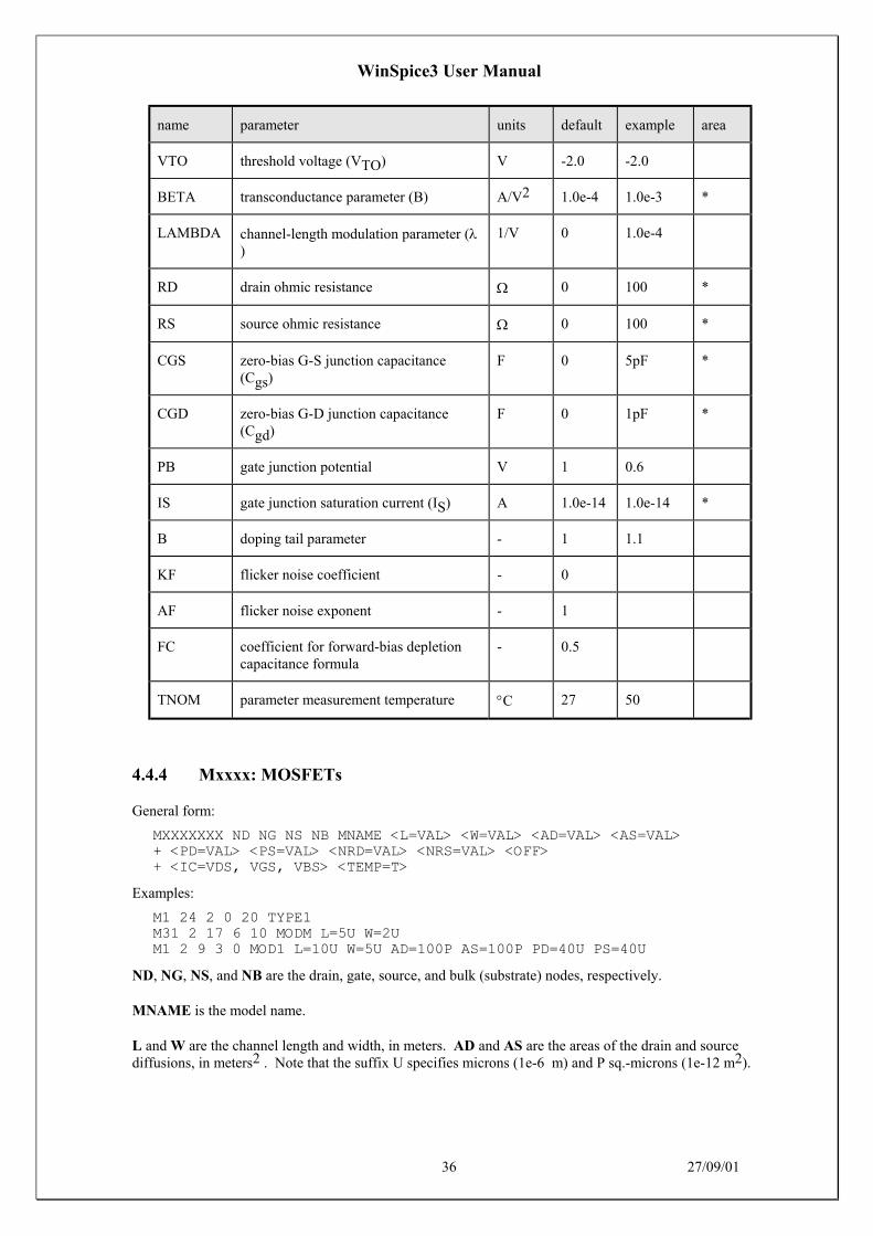
WinSpice3 User Manual
36 27/09/01
name parameter units default example area
VTO threshold voltage (VTO) V -2.0 -2.0
BETA transconductance parameter (B) A/V2 1.0e-4 1.0e-3 *
LAMBDA channel-length modulation parameter (λ)
1/V 0 1.0e-4
RD drain ohmic resistance Ω 0 100 *
RS source ohmic resistance Ω 0 100 *
CGS zero-bias G-S junction capacitance(Cgs)
F 0 5pF *
CGD zero-bias G-D junction capacitance(Cgd)
F 0 1pF *
PB gate junction potential V 1 0.6
IS gate junction saturation current (IS) A 1.0e-14 1.0e-14 *
B doping tail parameter - 1 1.1
KF flicker noise coefficient - 0
AF flicker noise exponent - 1
FC coefficient for forward-bias depletioncapacitance formula
- 0.5
TNOM parameter measurement temperature °C 27 50
4.4.4 Mxxxx: MOSFETs
General form:
MXXXXXXX ND NG NS NB MNAME <L=VAL> <W=VAL> <AD=VAL> <AS=VAL>+ <PD=VAL> <PS=VAL> <NRD=VAL> <NRS=VAL> <OFF>+ <IC=VDS, VGS, VBS> <TEMP=T>
Examples:
M1 24 2 0 20 TYPE1M31 2 17 6 10 MODM L=5U W=2UM1 2 9 3 0 MOD1 L=10U W=5U AD=100P AS=100P PD=40U PS=40U
ND, NG, NS, and NB are the drain, gate, source, and bulk (substrate) nodes, respectively.
MNAME is the model name.
L and W are the channel length and width, in meters. AD and AS are the areas of the drain and sourcediffusions, in meters2 . Note that the suffix U specifies microns (1e-6 m) and P sq.-microns (1e-12 m2).

WinSpice3 User Manual
37 27/09/01
If any of L, W, AD, or AS are not specified, the default values defined by the .OPTION control linevariables DEFL, DEFW, DEFAD and DEFAS are used (see section 5.1). The use of defaults simplifiesinput file preparation, as well as the editing required if device geometry's are to be changed.
PD and PS are the perimeters of the drain and source junctions, in meters and default to 0.0
NRD and NRS designate the equivalent number of squares of the drain and source diffusions; these valuesmultiply the sheet resistance RSH specified on the .MODEL control line for an accurate representation ofthe parasitic series drain and source resistance of each transistor. NRD and NRS default to 1.0.
OFF indicates an (optional) initial condition on the device for DC analysis. The (optional) initial conditionspecification using IC=VDS, VGS, VBS is intended for use with the UIC option on the .TRAN controlline, when a transient analysis is desired starting from other than the quiescent operating point. See the .ICcontrol line for a better and more convenient way to specify transient initial conditions.
The (optional) TEMP value is the temperature at which this device is to operate, and overrides thetemperature specification on the .OPTION control line. The temperature specification is ONLY valid forlevel 1, 2, 3, and 6 MOSFETs, not for level 4 or 5 (BSIM) devices.
4.4.4.1 MOSFET Models (NMOS/PMOS)
SPICE provides four MOSFET device models, which differ in the formulation of the I-V characteristic.The variable LEVEL specifies the model to be used:-
LEVEL=1 Shichman-Hodges
LEVEL=2 MOS2 (as described in [1])
LEVEL=3 MOS3, a semi-empirical model(see [1])
LEVEL=4 BSIM1 (as described in [3])
LEVEL=5 BSIM2 (as described in [5])
LEVEL=6 MOS6 (as described in [6])
LEVEL=8 BSIM3
LEVEL=9 B3SOI
LEVEL=14 BSIM4
LEVEL=44 EKV from Ecole Polytechnique Federale de Lausanne (seehttp://legwww.epfl.ch/ekv)
LEVEL=49 BSIM3 (same as LEVEL=8 for HSPICE compatibility)
Note that three versions of the BSIM3 model are supported by WinSpice. This is needed because differentversions of BSIM3 are not compatible with each other in term of the model parameters. The version isselected by placing a ‘VERSION=x.x.x’ option in the .MODEL line as follows:-
VERSION=3.1 BSIM3 v3.1
VERSION=3.2 BSIM3 v3.2
Omitted BSIM3 v3.2.2
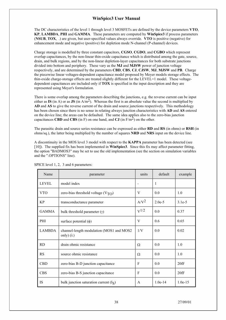
WinSpice3 User Manual
38 27/09/01
The DC characteristics of the level 1 through level 3 MOSFETs are defined by the device parameters VTO,KP, LAMBDA, PHI and GAMMA. These parameters are computed by WinSpice3 if process parameters(NSUB, TOX, .) are given, but user-specified values always override. VTO is positive (negative) forenhancement mode and negative (positive) for depletion mode N-channel (P-channel) devices.
Charge storage is modelled by three constant capacitors, CGSO, CGDO, and CGBO which representoverlap capacitances, by the non-linear thin-oxide capacitance which is distributed among the gate, source,drain, and bulk regions, and by the non-linear depletion-layer capacitances for both substrate junctionsdivided into bottom and periphery. These vary as the MJ and MJSW power of junction voltagerespectively, and are determined by the parameters CBD, CBS, CJ, CJSW, MJ, MJSW and PB. Chargethe piecewise linear voltages-dependent capacitance model proposed by Meyer models storage effects. Thethin-oxide charge-storage effects are treated slightly different for the LEVEL=1 model. These voltage-dependent capacitances are included only if TOX is specified in the input description and they arerepresented using Meyer's formulation.
There is some overlap among the parameters describing the junctions, e.g. the reverse current can be inputeither as IS (in A) or as JS (in A/m2). Whereas the first is an absolute value the second is multiplied byAD and AS to give the reverse current of the drain and source junctions respectively. This methodologyhas been chosen since there is no sense in relating always junction characteristics with AD and AS enteredon the device line; the areas can be defaulted. The same idea applies also to the zero-bias junctioncapacitances CBD and CBS (in F) on one hand, and CJ (in F/m2) on the other.
The parasitic drain and source series resistance can be expressed as either RD and RS (in ohms) or RSH (inohms/sq.), the latter being multiplied by the number of squares NRD and NRS input on the device line.
A discontinuity in the MOS level 3 model with respect to the KAPPA parameter has been detected (see[10]). The supplied fix has been implemented in WinSpice3. Since this fix may affect parameter fitting,the option "BADMOS3" may be set to use the old implementation (see the section on simulation variablesand the ".OPTIONS" line).
SPICE level 1, 2, 3 and 6 parameters:
Name parameter units default example
LEVEL model index - 1
VTO zero-bias threshold voltage (VTO) V 0.0 1.0
KP transconductance parameter A/V2 2.0e-5 3.1e-5
GAMMA bulk threshold parameter (γ) V1/2 0.0 0.37
PHI surface potential (φ) V 0.6 0.65
LAMBDA channel-length modulation (MOS1 and MOS2only) (λ)
1/V 0.0 0.02
RD drain ohmic resistance Ω 0.0 1.0
RS source ohmic resistance Ω 0.0 1.0
CBD zero-bias B-D junction capacitance F 0.0 20fF
CBS zero-bias B-S junction capacitance F 0.0 20fF
IS bulk junction saturation current (IS) A 1.0e-14 1.0e-15

WinSpice3 User Manual
39 27/09/01
Name parameter units default example
PB bulk junction potential V 0.8 0.87
CGSO gate-source overlap capacitance per meterchannel width
F/m 0.0 4.0e-11
CGDO gate-drain overlap capacitance per meterchannel width
F/m 0.0 4.0e-11
CGBO gate-bulk overlap capacitance per meterchannel length
F/m 0.0 2.0e-10
RSH drain and source diffusion sheet resistance Ω/[] 0.0 10.0
CJ zero-bias bulk junction bottom cap per sq.-meter of junction area
F/m2 0.0 2.0e-4
MJ bulk junction bottom grading coefficient. - 0.5 0.5
CJSW zero-bias bulk junction sidewall cap. per meterof junction perimeter
F/m 0.0 1.0e-9
MJSW bulk junction sidewall grading coefficient. - 0.50(level1)0.33(level2, 3)
JS bulk junction saturation current per sq.-meterof junction area
A/m2 1.0e-8
TOX Oxide thickness meter 1.0e-7 1.0e-7
NSUB Substrate doping 1/cm3 0.0 4.0e15
NSS Surface state density 1/cm2 0.0 1.0e10
NFS fast surface state density 1/cm2 0.0 1.0e10
TPG type of gate material:+1 opp. to substrate-1 same as substrate0 Al gate
- 1.0
XJ Metallurgical junction depth meter 0.0 1µ
LD lateral diffusion meter 0.0 0.8µ
UO surface mobility cm2/Vs 600 700
UCRIT critical field for mobility degradation (MOS2only)
V/cm 1.0e4 1.0e4
UEXP critical field exponent in mobility degradation(MOS2 only)
- 0.0 0.1

WinSpice3 User Manual
40 27/09/01
Name parameter units default example
UTRA Transverse field coefficient (mobility) (deletedfor MOS2)
- 0.0 0.3
VMAX Maximum drift velocity of carriers m/s 0.0 5.0e4
NEFF total channel-charge (fixed and mobile)coefficient (MOS2 only)
- 1.0 5.0
KF flicker noise coefficient - 0.0 1.0e-26
AF flicker noise exponent - 1.0 1.2
FC Coefficient for forward-bias depletioncapacitance formula
- 0.5
DELTA width effect on threshold voltage (MOS2 andMOS3)
- 0.0 1.0
THETA mobility modulation (MOS3 only) 1/V 0.0 0.1
ETA static feedback (MOS3 only) - 0.0 1.0
KAPPA Saturation field factor (MOS3 only) - 0.2 0.5
TNOM Parameter measurement temperature °C 27 50
The level 4 and level 5 (BSIM1 and BSIM2) parameters are all values obtained from processcharacterisation, and can be generated automatically. J. Pierret [4] describes a means of generating a'process' file, and the program Proc2Mod provided with WinSpice3 converts this file into a sequence ofBSIM1 ".MODEL" lines suitable for inclusion in a WinSpice3 input file. Parameters marked below withan * in the l/w column also have corresponding parameters with a length and width dependency. Forexample, VFB is the basic parameter with units of Volts, and LVFB and WVFB also exist and have units ofVolt-micrometer. The formula
effective
W
effective
L
W
P
L
PPP ++= 0
is used to evaluate the parameter for the actual device specified with
DLLL inputeffective −=
and
DWWW inputeffective −=
Note that unlike the other models in WinSpice3, the BSIM model is designed for use with a processcharacterisation system that provides all the parameters, thus there are no defaults for the parameters, andleaving one out is considered an error. For an example set of parameters and the format of a process file,see the SPICE2 implementation notes [3].
For more information on BSIM2, see reference [5].

WinSpice3 User Manual
41 27/09/01
SPICE BSIM (level 4) parameters.
name parameter units l/w
VFB flat-band voltage V *
PHI surface inversion potential V *
K1 body effect coefficient V1/2 *
K2 drain/source depletion charge-sharing coefficient - *
ETA zero-bias drain-induced barrier-lowering coefficient - *
MUZ zero-bias mobility cm2/V-s
DL shortening of channel µm
DW narrowing of channel µm
U0 zero-bias transverse-field mobility degradation coefficient V-1 *
U1 zero-bias velocity saturation coefficient µm/V *
X2MZ sens. of mobility to substrate bias at Vds=0 cm2/V2-s *
X2E sens. of drain-induced barrier lowering effect to substrate bias V-1 *
X3E sens. of drain-induced barrier lowering effect to drain bias atVds=Vdd
V-1 *
X2U0 sens. of transverse field mobility degradation effect to substratebias
V-2 *
X2U1 sens. of velocity saturation effect to substrate bias µmV-2 *
MUS mobility at zero substrate bias and at Vds=Vdd cm2/V2-s
X2MS sens. of mobility to substrate bias at Vds=Vdd cm2/V2-s *
X3MS sens. of mobility to drain bias at Vds=Vdd cm2/V2-s *
X3U1 sens. of velocity saturation effect on drain bias at Vds=Vdd µmV *
TOX gate oxide thickness µm
TEMP temperature at which parameters were measured °C
VDD measurement bias range V
CGDO gate-drain overlap capacitance per meter channel width F/m
CGSO gate-source overlap capacitance per meter channel width F/m
CGBO gate-bulk overlap capacitance per meter channel length F/m

WinSpice3 User Manual
42 27/09/01
name parameter units l/w
XPART gate-oxide capacitance-charge model flag -
N0 zero-bias sub threshold slope coefficient - *
NB sens. of sub threshold slope to substrate bias - *
ND sens. of sub threshold slope to drain bias - *
RSH drain and source diffusion sheet resistance Ω/[]
JS source drain junction current density A/m2
PB built in potential of source drain junction V
MJ Grading coefficient of source drain junction -
PBSW built in potential of source, drain junction sidewall V
MJSW grading coefficient of source drain junction sidewall -
CJ Source drain junction capacitance per unit area F/m2
CJSW source drain junction sidewall capacitance per unit length F/m
WDF source drain junction default width m
DELL Source drain junction length reduction m
XPART = 0 selects a 40/60 drain/source charge partition in saturation, while XPART=1 selects a 0/100drain/source charge partition.
ND, NG, and NS are the drain, gate, and source nodes, respectively.
MNAME is the model name, AREA is the area factor, and OFF indicates an (optional) initial condition onthe device for DC analysis. If the area factor is omitted, a value of 1.0 is assumed.
The (optional) initial condition specification, using IC=VDS, VGS is intended for use with the UIC optionon the .TRAN control line, when a transient analysis is desired starting from other than the quiescentoperating point. See the .IC control line for a better way to set initial conditions.
4.4.5 Zxxxx: MESFETs
General form:
ZXXXXXXX ND NG NS MNAME <AREA> <OFF> <IC=VDS, VGS>
Examples:
Z1 7 2 3 ZM1 OFF
4.4.5.1 MESFET Models (NMF/PMF)
The MESFET model is derived from the GaAs FET model of Statz et al. as described in [11]. The DCcharacteristics are defined by the parameters VTO, B, and BETA, which determine the variation of draincurrent with gate voltage, ALPHA, which determines saturation voltage, and LAMBDA, which determinesthe output conductance. The formula are given by:

WinSpice3 User Manual
43 27/09/01
( )( ) ( )ds
ds
Tgs
Tgsd V
V
VVb
VVI λα
β+
−−
−+−
= 13
111
32
for 03
< <Vds α
( )( ) ( )I
V V
b V VVd
gs T
gs T
ds=−
+ −+
βλ
2
11 for Vds >
3
α
Two ohmic resistances, RD and RS, are included. Charge storage is modelled by total gate charge as afunction of gate-drain and gate-source voltages and is defined by the parameters CGS, CGD, and PB.
name Parameter units default example area
VTO pinch-off voltage V -2.0 -2.0
BETA transconductance parameter A/V2 1.0e-4 1.0e-3 *
B doping tail extending parameter 1/V 0.3 0.3 *
ALPHA saturation voltage parameter 1/V 2 2 *
LAMBDA
channel-length modulationparameter
1/V 0 1.0e-4
RD drain ohmic resistance Ω 0 100 *
RS source ohmic resistance Ω 0 100 *
CGS zero-bias G-S junctioncapacitance
F 0 5pF *
CGD zero-bias G-D junctioncapacitance
F 0 1pF *
PB gate junction potential V 1 0.6
KF flicker noise coefficient - 0
AF flicker noise exponent - 1
FC coefficient for forward-biasdepletion capacitance formula
- 0.5

WinSpice3 User Manual
44 27/09/01
5 ANALYSES AND OUTPUT CONTROL
The following command lines are for specifying analyses or plots within the circuit description file.Parallel commands exist in the interactive command interpreter (detailed in the following section).Specifying analyses and plots (or tables) in the input file is useful for batch runs. Batch mode is enteredwhen either the -b option is given or when the default input source is redirected from a file. In batch mode,the analyses specified by the control lines in the input file (e.g. ".ac", ".tran", etc.) are immediately executed(unless “.control” lines exist; see the section on the interactive command interpreter).
Output plots (in "line-printer" form) and tables can be printed according to the .PRINT, .PLOT, and .FOURcontrol lines, described next. .PLOT, .PRINT, and .FOUR lines are meant for compatibility with SPICE2.
5.1 .OPTIONS: Simulator Variables
Various parameters of the simulations available in WinSpice3 can be altered to control the accuracy, speed,or default values for some devices. These parameters may be changed via the "set" command (describedlater in the section on the interactive front-end) or via the ".OPTIONS" line:
General form:
.OPTIONS OPT1 OPT2 ... (or OPT=OPTVAL ...)
Examples:
.OPTIONS RELTOL=.005 TRTOL=8
The options line allows the user to reset program control and user options for specific simulation purposes.See the following section on the interactive command interpreter for the parameters that may be set with a.OPTIONS line and the format of the 'set' command. Any combination of the following options may beincluded, in any order. 'x' (below) represents some positive number.

WinSpice3 User Manual
45 27/09/01
option effect
ABSTOL=x Sets the absolute current error tolerance of the program.The default value is 1 picoamp.
BADMOS3 Use the older version of the MOS3 model with the "kappa" discontinuity.
BYPASS=x This option, when set to a non-zero value, avoids recomputation of nonlinearfunctions that do not change with iterations.
The default value is 0.
CAPBRANCH Calculate capacitor branch currents during analyses. This is an experimentalfeature which can cause convergence problems but which may be useful insome cases.
CHGTOL=x Sets the charge tolerance of the program. The default value is 1.0e-14.
DEFAD=x Sets the value for MOS drain diffusion area; the default is 0.0.
DEFAS=x Sets the value for MOS source diffusion area; the default is 0.0.
DEFL=x Sets the value for MOS channel length; the default is 100.0 micrometer.
DEFW=x Sets the value for MOS channel width; the default is 100.0 micrometer.
DELMIN=x Sets the minimum timestep value used in transient analyses. If WinSpice3tries to go below this value in attempting to achieve convergence, theanalysis will be aborted.
A value of 0 disables the minimum limit. Any negative value sets theminimum timestep to (1E-9*TMAX) as in the original Spice3.
The default value is –1.
GMIN=x Sets the value of GMIN, the minimum conductance allowed by the program.The default value is 1.0e-12.
ITL1=x Sets the DC iteration limit. The default is 100.
ITL2=x Sets the DC transfer curve iteration limit. The default is 50.
ITL3=x Sets the lower transient analysis iteration limit. The default value is 4.(Note: not implemented in WinSpice3).
ITL4=x Sets the transient analysis timepoint iteration limit. The default is 10.
ITL5=x Sets the transient analysis total iteration limit. A value of 0 (the default)disables this limit.
KEEPOPINFO Retain the operating point information when an AC, Distortion, or Pole-Zeroanalysis is run. This is particularly useful if the circuit is large and you donot want to run a (redundant) ".OP" analysis.

WinSpice3 User Manual
46 27/09/01
option effect
METHOD=name Sets the numerical integration method used by SPICE. Possible names are"Gear" or "trapezoidal" (or just "trap").
The default is trapezoidal.
MINTIMESTEP=x The same as DELMIN.
PIVREL=x Sets the relative ratio between the largest column entry and an acceptablepivot value. The default value is 1.0e-3.
In the numerical pivoting algorithm the allowed minimum pivot value isdetermined by
EPSREL=AMAX1(PIVREL*MAXVAL, PIVTOL)
where MAXVAL is the maximum element in the column where a pivot issought (partial pivoting).
PIVTOL=x Sets the absolute minimum value for a matrix entry to be accepted as a pivot.The default value is 1.0e-13.
RELTOL=x Resets the relative error tolerance of the program. The default value is 0.001(0.1%).
RESBRANCH Calculate resistor branch currents during analyses. This is an experimentalfeature which can cause convergence problems but which may be useful insome cases.
RSHUNT=x Shunt resistors of value x are placed between all voltage nodes and node 0(the ground node). This helps avoid nodes having no DC paths to groundand hence not converging. It also allow for more realistic circuits to besimulated.
If x is zero, shunt resistors are not placed in the circuit.
By default, x = 0.
SCALE=x Element scaling factor used as a multiplier for device dimension parametersL, W, AD, AS, PD and PS. Currently used only used by the followingdevice models:-
MOS1 (MOSFET level 1)MOS2 (MOSFET level 2)MOS3 (MOSFET level 3)BSIM1 (MOSFET level 4)BSIM2 (MOSFET level 5)MOS6 (MOSFET level 6)BSIM3 (MOSFET level 8)EKV (MOSFET level 44)
The default value is 1.0.
TEMP=x Sets the operating temperature of the circuit. The default value is 27 deg C(300 deg K). TEMP can be overridden by a temperature specification on anytemperature dependent instance.

WinSpice3 User Manual
47 27/09/01
option effect
TNOM=x Sets the nominal temperature at which device parameters are measured. Thedefault value is 27 deg C (300 deg K).
TNOM can be overridden by a specification on any temperature dependentdevice model.
TRTOL=x Sets the transient error tolerance. The default value is 7.0. This parameter isan estimate of the factor by which SPICE overestimates the actual truncationerror.
TRYTOCOMPACT Applicable only to the LTRA model.
When specified, the simulator tries to condense LTRA transmission lines'past history of input voltages and currents.
VNTOL=x Sets the absolute voltage error tolerance of the program. The default value is1 microvolt.
In addition, the following options have the listed effect when operating in SPICE2 emulation mode:
option effect
ACCT causes accounting and run time statistics to be printed
LIST causes the summary listing of the input data to be printed
NOMOD suppresses the printout of the model parameters
NOPAGE suppresses page ejects
NODE causes the printing of the node table.
OPTS causes the option values to be printed.
5.2 Initial Conditions
5.2.1 .NODESET: Specify Initial Node Voltage Guesses
General form:
.NODESET V(NODNUM)=VAL V(NODNUM)=VAL ...
Examples:
.NODESET V(12)=4.5 V(4)=2.23
The Nodeset line helps the program find the DC or initial transient solution by making a preliminary passwith the specified nodes held to the given voltages. The restriction is then released and the iterationcontinues to the true solution. The .NODESET line may be necessary for convergence on bistable or a-stable circuits. In general, this line should not be necessary.

WinSpice3 User Manual
48 27/09/01
5.2.2 .IC: Set Initial Conditions
General form:
.IC V(NODNUM)=VAL V(NODNUM)=VAL ...
Examples:
.IC V(11)=5 V(4)=-5 V(2)=2.2
The IC line is for setting transient initial conditions. It has two different interpretations, depending onwhether the UIC parameter is specified on the .TRAN control line. Also, one should not confuse this linewith the .NODESET line. The .NODESET line is only to help DC convergence, and does not affect finalbias solution (except for multi-stable circuits). The two interpretations of this line are as follows:
1. When the UIC parameter is specified on the .TRAN line, then the node voltages specified on the.IC control line are used to compute the capacitor, diode, BJT, JFET, and MOSFET initialconditions. This is equivalent to specifying the IC=... parameter on each device line, but is muchmore convenient. The IC=... parameter can still be specified and takes precedence over the .ICvalues. Since no DC bias (initial transient) solution is computed before the transient analysis, oneshould take care to specify all DC source voltages on the .IC control line if they are to be used tocompute device initial conditions.
2. When the UIC parameter is not specified on the .TRAN control line, the DC bias (initial transient)solution is computed before the transient analysis. In this case, the node voltages specified on the.IC control line are forced to the desired initial values during the bias solution. During transientanalysis, the constraint on these node voltages is removed. This is the preferred method since itallows SPICE to compute a consistent DC solution.
5.3 Analyses
5.3.1 .AC: Small-Signal AC Analysis
General form:
.AC DEC ND FSTART FSTOP
.AC OCT NO FSTART FSTOP
.AC LIN NP FSTART FSTOP
Examples:
.AC DEC 10 1 10K
.AC DEC 10 1K 100MEG
.AC LIN 100 1 100HZ
DEC stands for decade variation, and ND is the number of points per decade. OCT stands for octavevariation, and NO is the number of points per octave. LIN stands for linear variation, and NP is thenumber of points. FSTART is the starting frequency, and FSTOP is the final frequency. If this line isincluded in the input file, WinSpice3 performs an AC analysis of the circuit over the specified frequencyrange. Note that in order for this analysis to be meaningful, at least one independent source must have beenspecified with an AC value.

WinSpice3 User Manual
49 27/09/01
5.3.2 .DC: DC Transfer Function
General form:
.DC SRCNAM VSTART VSTOP VINCR [SRC2 START2 STOP2 INCR2]
Examples:
.DC VIN 0.25 5.0 0.25
.DC VDS 0 10 .5 VGS 0 5 1
.DC VCE 0 10 .25 IB 0 10U 1U
The DC line defines the DC transfer curve source and sweep limits (again with capacitors open andinductors shorted). SRCNAM is the name of an independent voltage or current source. VSTART,VSTOP, and VINCR are the starting, final, and incrementing values respectively.
The first example causes the value of the voltage source VIN to be swept from 0.25 Volts to 5.0 Volts inincrements of 0.25 Volts. A second source (SRC2) may optionally be specified with associated sweepparameters. In this case, the first source is swept over its range for each value of the second source. Thisoption can be useful for obtaining semiconductor device output characteristics. See the second examplecircuit description in Appendix A.
5.3.3 .DISTO: Distortion Analysis
General form:
.DISTO DEC ND FSTART FSTOP <F2OVERF1>
.DISTO OCT NO FSTART FSTOP <F2OVERF1>
.DISTO LIN NP FSTART FSTOP <F2OVERF1>
Examples:
.DISTO DEC 10 1kHz 100Mhz
.DISTO DEC 10 1kHz 100Mhz 0.9
The DISTO line does a small-signal distortion analysis of the circuit. A multi-dimensional Volterra seriesanalysis is done using multi-dimensional Taylor series to represent the nonlinearities at the operating point.Terms of up to third order are used in the series expansions.
If the optional parameter F2OVERF1 is not specified, .DISTO does a harmonic analysis - i.e., it analysesdistortion in the circuit using only a single input frequency F1, which is swept as specified by arguments ofthe .DISTO command exactly as in the .AC command. Inputs at this frequency may be present at morethan one input source, and their magnitudes and phases are specified by the arguments of the DISTOF1keyword in the input file lines for the input sources (see the description for independent sources - thearguments of the DISTOF2 keyword are not relevant in this case). The analysis produces informationabout the AC values of all node voltages and branch currents at the harmonic frequencies 2F1 and 3F1, vs.the input frequency F1 as it is swept. A value of 1 (as a complex distortion output) signifies cos(2J(2F1)t)at 2F1 and cos(2J(3F1)t) at 3F1, using the convention that 1 at the input fundamental frequency isequivalent to cos(2JF1t). The distortion component desired (2F1 or 3F1) can be selected using commandsin WinSpice3, and then printed or plotted (normally, one is interested primarily in the magnitude of theharmonic components, so the magnitude of the AC distortion value is looked at). It should be noted thatthese are the AC values of the actual harmonic components, and are not equal to HD2 and HD3. To obtainHD2 and HD3, one must divide by the corresponding AC values at F1, obtained from a .AC line. Thisdivision can be done using WinSpice3 commands.
If the optional F2OVERF1 parameter is specified, it should be a real number between (and not equal to) 0.0and 1.0; in this case, .DISTO does a spectral analysis. It considers the circuit with sinusoidal inputs at twodifferent frequencies F1 and F2. F1 is swept according to the .DISTO control line options exactly as in the.AC control line. F2 is kept fixed at a single frequency as F1 sweeps - the value at which it is kept fixed isequal to F2OVERF1 times FSTART. Each independent source in the circuit may potentially have two(superimposed) sinusoidal inputs for distortion, at the frequencies F1 and F2. The magnitude and phase ofthe F1 component are specified by the arguments of the DISTOF1 keyword in the source's input line (seethe description of independent sources); the magnitude and phase of the F2 component are specified by the

WinSpice3 User Manual
50 27/09/01
arguments of the DISTOF2 keyword. The analysis produces plots of all node voltages/branch currents atthe intermodulation product frequencies F1 + F2, F1 - F2, and (2 F1) - F2, vs. the swept frequency F1. TheIM product of interest may be selected using the Setplot command, and displayed with the print and plotcommands. It is to be noted as in the harmonic analysis case, the results are the actual AC voltages andcurrents at the intermodulation frequencies, and need to be normalised with respect to .AC values to obtainthe IM parameters.
If the DISTOF1 or DISTOF2 keywords are missing from the description of an independent source, thenthat source is assumed to have no input at the corresponding frequency. The default values of themagnitude and phase are 1.0 and 0.0 respectively. The phase should be specified in degrees.
It should be carefully noted that the number F2OVERF1 should ideally be an irrational number. Since thisis not possible in practice, efforts should be made to keep the denominator in its fractional representation aslarge as possible, certainly above 3, for accurate results. That is, if F2OVERF1 is represented as a fractionA/B, where A and B are integers with no common factors, B should be as large as possible. Note that A <B because F2OVERF1 is constrained to be < 1.
To illustrate why, consider the cases where F2OVERF1 is 49/100 and 1/2. In a spectral analysis, theoutputs produced are at F1 + F2, F1 - F2 and 2 F1 - F2. In the latter case, F1 - F2 = F2, so the result at theF1-F2 component is erroneous because there is the strong fundamental F2 component at the samefrequency. Also, F1 + F2 = 2 F1 - F2 in the latter case, and each result is erroneous individually. Thisproblem is not there in the case where F2OVERF1 = 49/100, because F1-F2 = 51/100 F1 < > 49/100 F1 =F2. In this case, there are two very closely spaced frequency components at F2 and F1 - F2. One of theadvantages of the Volterra series technique is that it computes distortions at mix frequencies expressedsymbolically (i.e. n F1 + m F2). Therefore one is able to obtain the strengths of distortion componentsaccurately even if the separation between them is very small, as opposed to transient analysis for example.The disadvantage is of course that if two of the mix frequencies coincide, the results are not mergedtogether and presented (though this could presumably be done as a post-processing step). Currently, theinterested user should keep track of the mix frequencies and add the distortions at coinciding mixfrequencies together, should it be necessary.
5.3.4 .NOISE: Noise Analysis
General form:
.NOISE V(OUTPUT <,REF>) SRC ( DEC | LIN | OCT ) PTS FSTART FSTOP+ <PTS_PER_SUMMARY>
Examples:
.NOISE V(5) VIN DEC 10 1kHZ 100Mhz
.NOISE V(5,3) V1 OCT 8 1.0 1.0e6 1
The Noise line does a noise analysis of the circuit.
OUTPUT is the node at which the total output noise is desired; if REF is specified, then the noise voltageV(OUTPUT) - V(REF) is calculated. By default, REF is assumed to be ground. SRC is the name of anindependent source to which input noise is referred. PTS, FSTART and FSTOP are .AC type parametersthat specify the frequency range over which plots are desired. PTS_PER_SUMMARY is an optionalinteger; if specified, the noise contributions of each noise generator is produced everyPTS_PER_SUMMARY frequency points. These are stored in the spectral density curves (use 'Setplot'command to select the correct set of curves.
The .NOISE control line produces two plots - one for the Noise Spectral Density curves and one for thetotal Integrated Noise over the specified frequency range. All noise voltages/currents are in units ofV/Hz0.5 and A/Hz0.5 for spectral density, V and A for integrated noise.
NOTE: The output units are different from Berkeley Spice3. The output units for Berkeley Spice3 are inV2/Hz and A2/Hz for spectral density and V2 and A2 for integrated noise. This was changed to the formatused by Spice2, Pspice etc for consistency and to prevent confusion.

WinSpice3 User Manual
51 27/09/01
For examples, take the simple circuit below:-
simple resistor circuit*simple resistor circuit to test which ones of vspice, uf77spice and* spice3 give the correct results
iin 1 0 1m ACrl 1 0 1k
.noise v(1) iin dec 10 10 100k 1
.print noise onoise
.end
A sample session showing how WinSpice3 stores the results is shown below.
Spice 1 -> runNoise analysis ...Spice 2 -> setplot Type the name of the desired plot:
new New plotCurrent noise2 simple resistor circuit (Integrated Noise - V or A) noise1 simple resistor circuit (Noise Spectral DensityCurves - (V or A)/sqrt(Hz)) const Constant values (constants)? noise1Spice 3 -> displayHere are the vectors currently active:
Title: simple resistor circuitName: noise1 (Noise Spectral Density Curves - (V or A)/sqrt(Hz))Date: Tue Aug 20 23:35:17 1996
frequency : frequency, real, 41 long, grid = xlog[default scale] inoise_spectrum : voltage, real, 41 long onoise_rl : voltage, real, 41 long onoise_spectrum : voltage, real, 41 longSpice 4 ->
The onoise_rl plot contains the noise contributions of resistor rl at each frequency point. If the last optionon the .noise line had been omitted, this vector would not have been created.
NOTE: in SPICE2 the syntax for .noise lines was different and SPICE2 required an .AC line to be present.The .AC line is not required for WinSpice3. For your information, to make the circuit above work onSPICE2, the .noise line above would need to be replaced by
.ac dec 10 10 100k
.noise v(1) iin 1
5.3.5 .OP: Operating Point Analysis
General form:
.OP
The inclusion of this line in an input file directs WinSpice3 to determine the DC operating point of thecircuit with inductors shorted and capacitors opened.
NOTE: a DC analysis is automatically performed prior to a transient analysis to determine the transientinitial conditions, and prior to an AC small-signal, Noise, and Pole-Zero analysis to determine thelinearized, small-signal models for non-linear devices (see the KEEPOPINFO in section 5.1).

WinSpice3 User Manual
52 27/09/01
5.3.6 .PZ: Pole-Zero Analysis
General form:
.PZ NODE1 NODE2 NODE3 NODE4 CUR POL
.PZ NODE1 NODE2 NODE3 NODE4 CUR ZER
.PZ NODE1 NODE2 NODE3 NODE4 CUR PZ
.PZ NODE1 NODE2 NODE3 NODE4 VOL POL
.PZ NODE1 NODE2 NODE3 NODE4 VOL ZER
.PZ NODE1 NODE2 NODE3 NODE4 VOL PZ
Examples:
.PZ 1 0 3 0 CUR POL
.PZ 2 3 5 0 VOL ZER
.PZ 4 1 4 1 CUR PZ
CUR stands for a transfer function of the type (output voltage)/(input current) while VOL stands for atransfer function of the type (output voltage)/(input voltage). POL stands for pole analysis only, ZER forzero analysis only and PZ for both. This feature is provided mainly because if there is a non-convergencein finding poles or zeros, then, at least the other can be found. Finally, NODE1 and NODE2 are the twoinput nodes and NODE3 and NODE4 are the two output nodes. Thus, there is complete freedom regardingthe output and input ports and the type of transfer function.
In interactive mode (see section 6.12.30), the command syntax is the same except that the first field is PZinstead of .PZ. To print the results, one should use the command 'print all'.
5.3.7 .SENS: DC or Small-Signal AC Sensitivity Analysis
General form:
.SENS OUTVAR
.SENS OUTVAR AC DEC ND FSTART FSTOP
.SENS OUTVAR AC OCT NO FSTART FSTOP
.SENS OUTVAR AC LIN NP FSTART FSTOP
Examples:
.SENS V(1,OUT)
.SENS V(OUT) AC DEC 10 100 100k
.SENS I(VTEST)
The sensitivity of OUTVAR to all non-zero device parameters is calculated when the SENS analysis isspecified. OUTVAR is a circuit variable (node voltage or voltage-source branch current).
The first form calculates sensitivity of the DC operating-point value of OUTVAR.
The second, third and fourth forms calculate sensitivity of the AC values of OUTVAR. The parameterslisted for AC sensitivity are the same as in an AC analysis (see ".AC" above). The output values are indimensions of change in output per unit change of input (as opposed to percent change in output or perpercent change of input).
5.3.8 .TF: Transfer Function Analysis
General form:
.TF OUTVAR INSRC
Examples:
.TF V(5, 3) VIN
.TF I(VLOAD) VIN
The TF line defines the small-signal output and input for the DC small-signal analysis. OUTVAR is thesmall signal output variable and INSRC is the small-signal input source. If this line is included,WinSpice3 computes the DC small-signal value of the transfer function (output/input), input resistance,
WinSpice3 User Manual
53 27/09/01
and output resistance. For the first example, WinSpice3 would compute the ratio of V(5, 3) to VIN, thesmall-signal input resistance at VIN, and the small-signal output resistance measured across nodes 5 and 3.
5.3.9 .TRAN: Transient Analysis
General form:
.TRAN TSTEP TSTOP <TSTART <TMAX>>
Examples:
.TRAN 1NS 100NS
.TRAN 1NS 1000NS 500NS
.TRAN 10NS 1US
TSTEP is the printing or plotting increment for line printer output. For use with the post processor,TSTEP is the suggested computing increment.
TSTOP is the final time, and TSTART is the initial time. If TSTART is omitted, it is assumed to be zero.The transient analysis always begins at time zero. In the interval <zero, TSTART>, the circuit is analysed(to reach a steady state), but no outputs are stored. In the interval <TSTART, TSTOP>, the circuit isanalysed and outputs are stored.
TMAX is the maximum step size that WinSpice3 uses. By default, the program chooses either TSTEP or(TSTOP-TSTART)/50.0, whichever is smaller. TMAX is useful when one wishes to guarantee acomputing interval that is smaller than the printer increment, TSTEP.
UIC (use initial conditions) is an optional keyword that indicates that the user does not want WinSpice3 tosolve for the quiescent operating point before beginning the transient analysis. If this keyword is specified,WinSpice3 uses the values specified using IC=... on the various elements as the initial transient conditionand proceeds with the analysis. If the .IC control line has been specified, then the node voltages on the .ICline are used to compute the initial conditions for the devices. Look at the description on the .IC controlline for its interpretation when UIC is not specified.
NOTE: WinSpice3 uses a dynamic timestep algorithm where the timestep is varied according to the slopeof the output curve. This helps to speed up analysis during parts of the curve that have small rates ofchange and concentrate the analysis where the rate of change is high. For this reason, the value of TSTEPis only used as a guide to the initial timestep.
A minimum timestep can be enforced in WinSpice3 using the DELMIN or MINTIMESTEP systemvariables (see section 5.1 in this document).
5.4 Batch Output
These lines are ignored by the interactive WinSpice3 and are only handled by the batch mode versions(cspice and bspice). They are provided for backward compatibility with SPICE2.
5.4.1 .SAVE Lines
General form:
.SAVE vector vector vector ...
Examples:
.SAVE i(vin) input output
.SAVE @m1[id]
.SAVE ALL
The vectors listed on the .SAVE line are recorded in the rawfile for use later with WinSpice3. Thestandard vector names are accepted.

WinSpice3 User Manual
54 27/09/01
If no .SAVE line is given, then the default set of vectors is saved (all node voltages and voltage sourcebranch currents). If .SAVE lines are given, only those vectors specified are saved.
For more discussion on internal device data, see Appendix B. See also the section on the interactivecommand interpreter for information on how to use the rawfile. The interactive version of this statement isdescribed in section 6.12.38.
5.4.2 .PRINT Lines
General form:
.PRINT PRTYPE OV1 <OV2 ... OV8>
Examples:
.PRINT TRAN V(4) I(VIN)
.PRINT DC V(2) I(VSRC) V(23, 17)
.PRINT AC VM(4, 2) VR(7) VP(8, 3)
The Print line defines the contents of a tabular listing of one to eight output variables. PRTYPE is the typeof the analysis (DC, AC, TRAN, NOISE, or DISTO) for which the specified outputs are desired. SPICE2restricts the output variable to the following forms (though this restriction is not enforced by WinSpice3):
V(N1<,N2>)
specifies the voltage difference between nodes N1 and N2. If N2 (and the preceding comma) is omitted,ground (0) is assumed. For AC analysis, V(N1<,N2>) gives the magnitude of the complex voltage. Forcompatibility with SPICE2, the following five additional values can be accessed for the AC analysis byreplacing the "V" in V(N1,N2) with:
V magnitude (same as VM below)
VR real part
VI imaginary part
VM magnitude
VP phase (in radians or degrees - see the units variable description)
VDB 20 log10(magnitude)
I(VXXXXXXX)
specifies the current flowing in the independent voltage source named VXXXXXXX. Positive currentflows from the positive node, through the source, to the negative node. For the AC analysis, thecorresponding replacements for the letter I may be made in the same way as described for voltage outputsi.e.
I magnitude (same as IM below)
IR real part
II imaginary part
IM magnitude
IP phase (in radians or degrees - see the units variable description)
WinSpice3 User Manual
55 27/09/01
IDB 20 log10(magnitude)
Output variables for the noise and distortion analyses have a different general form from that of the otheranalyses.
There is no limit on the number of .PRINT lines for each type of analysis.
5.4.3 .PLOT Lines
General form:
.PLOT PLTYPE OV1 <(PLO1, PHI1)> <OV2 <(PLO2, PHI2)> ... OV8>
Examples:
.PLOT DC V(4) V(5) V(1)
.PLOT TRAN V(17, 5) (2,5) I(VIN) V(17) (1,9)
.PLOT AC VM(5) VM(31, 24) VDB(5) VP(5)
.PLOT DISTO HD2 HD3(R) SIM2
.PLOT TRAN V(5,3) V(4) (0,5) V(7) (0,10)
The Plot line defines the contents of one plot of from one to eight output variables. PLTYPE is the type ofanalysis (DC, AC, TRAN, NOISE, or DISTO) for which the specified outputs are desired. The syntax forthe OV1 is identical to that for the .PRINT line and for the plot command in the interactive mode.
The letter X indicates the overlap of two or more traces on any plot.
When more than one output variable appears on the same plot, the first variable specified is printed as wellas plotted. If a printout of all variables is desired, then a companion .PRINT line should be included.
There is no limit on the number of .PLOT lines specified for each type of analysis.
5.4.4 .FOUR: Fourier Analysis of Transient Analysis Output
General form:
.FOUR FREQ OV1 <OV2 OV3 ...>
Examples:
.FOUR 100K V(5)
The Four (or Fourier) line controls whether WinSpice3 performs a Fourier analysis as a part of thetransient analysis. FREQ is the fundamental frequency, and OV1 the desired output vector. The Fourieranalysis is performed over the interval <TSTOP-period, TSTOP>, where TSTOP is the final time specifiedfor the transient analysis, and period is one period of the fundamental frequency. The DC component andthe first nine harmonics are determined. For maximum accuracy, TMAX (see the .TRAN line) should beset to period/100.0 (or less for very high-Q circuits).

WinSpice3 User Manual
56 27/09/01
6 INTERACTIVE INTERPRETER
WinSpice3 consists of a simulator and a front-end for data analysis and plotting. The command lineinterface has most of the capabilities of the UNIX C-shell.
WinSpice3 can plot data from a simulation on a graphics terminal or a workstation display. Note that theraw output file is different from the data that SPICE2 writes to the standard output.
6.1 Command Interpretation
If a word is typed as a command, and there is no built-in command with that name, the directories in thesourcepath list (see section 6.2) are searched in order for the file. If it is found, it is read in as a commandfile (as if it had been loaded using the source command – see section 6.12.49).
Before it is read, however, the variable argc is set to the number of words following the filename on thecommand line, and argv is set to a list of those words. After the file is finished, these variables are unset.Note that if a command file calls another, it must save its argv and argc since they are altered. Also,command files may not be re-entrant since there are no local variables (of course, the procedures mayexplicitly manipulate a stack...). This way one can write scripts analogous to UNIX shell scripts forWinSpice3.
Note that for the script to work with WinSpice3, it must begin with a blank line (or whatever else, since itis thrown away) and then a line with .control on it. This is an unfortunate result of the source commandbeing used for both circuit input and command file execution. Note also that this allows the user to merelytype the name of a circuit file as a command and it is automatically run. The commands are executedimmediately, without running any analyses that may be specified in the circuit (to execute the analysesbefore the script executes, include a run command in the script).
C-shell type quoting with "" and '', and backquote substitution may be used. Within single quotes, nofurther substitution (like history substitution) is done, and within double quotes, the words are kept togetherbut further substitution is done. Any text between backquotes is replaced by the result of executing the textas a command to the shell.
If any command takes a filename, the filename must be enclosed in double quotes if the filename containsspaces (as is permitted in Windows long filenames).
You may type multiple commands on one line, separated by semicolons.
There are various command scripts installed in \???\lib\scripts (where \??? is the directory containing the.EXE file), and the default sourcepath variable includes this directory, so you can use these command files(almost) like built-in commands. In fact, the setplot command is actually implemented as a script in thisway.
6.2 Variables
The operation of WinSpice3 may be affected by setting variables with the set command. In addition to thevariables mentioned below, the set command in WinSpice3 also affect the behaviour of the simulator viathe options previously described under the section on ".OPTIONS".
Variables can contain text strings, numbers or be Boolean (i.e. have the meaning TRUE or FALSE).Variables can be defined and deleted with the set and unset commands (see later). String and numbervariables can be defined with a command of the form:-
set variable=value
Boolean variables are a little odd in that they take the value TRUE if they are defined and FALSE if theydo not exist. For example, the variable slowplot can be set to TRUE with the command
set slowplot

WinSpice3 User Manual
57 27/09/01
Setting a variable like slowplot to FALSE is done with the command
unset slowplot
The variables in WinSpice3 which may be altered by the set command are:
Variable Type Description
appendwrite Boolean Append to the file when a write command is issued, if onealready exists.
colorN These variables determine the colours used, if X is being runon a colour display. N may be between 0 and 15. Colour 0 isthe background, colour 1 is the grid and text colour, andcolours 2 through 15 are used in order for vectors plotted. Thevalue of the colour variables should be names of colours,which may be found in the file /usr/lib/rgb.txt.
cpdebug Boolean Print cshpar debugging information (must be complied with the-DCPDEBUG flag). Unsupported in the current release.
debug Boolean If set then a lot of debugging information is printed (must becompiled with the -DFTEDEBUG flag). Unsupported in thecurrent release.
device String The name (/dev/tty??) of the graphics device. If this variableisn't set then the user's terminal is used. To do plotting onanother monitor you probably have to set both the device andterm variables. (If device is set to the name of a file,WinSpice3 dumps the graphics control codes into this file --this is useful for saving plots.)
diff_abstol Real The absolute tolerance used by the diff command.
diff_reltol Real The relative tolerance used by the diff command.
diff_vntol Real The absolute voltage tolerance used by the diff command.
echo Boolean Print out each command before it is executed.
filetype String This can be either ascii or binary, and determines the fileformat used by the write command (see section 6.12.66) isused.
The default is ascii.
fourgridsize Number How many points to use for interpolating into when doingFourier analysis.
gridsize Number If this variable is set to an integer, this number is used as thenumber of equally spaced points to use for the Y-axis whenplotting. Otherwise the current scale is used (which may nothave equally spaced points). If the current scale isn't strictlymonotonic, then this option has no effect.

WinSpice3 User Manual
58 27/09/01
Variable Type Description
gridstyle String Sets the style of grid to be used. The possible values are:-lingridloglogxlogylogsmithsmithgridpolarnogrid
See the plot command for details.
hcopydev String If this is set, when the hardcopy command is run the resultingfile is automatically printed on the printer named hcopydevwith the command lpr -Phcopydev -g file.
hcopyfont String This variable specifies the font name for hardcopy output plots.The value is device dependent.
hcopyfontsize String The font size for hardcopy plots.
hcopyfontscale String This is a scaling factor for the font used in hardcopy plots.
hcopydevtype String This variable specifies the type of the printer output to use inthe hardcopy command. If hcopydevtype is not set, plot(5)format is assumed. The standard distribution currentlyrecognises postscript as an alternative output format. Whenused in conjunction with hcopydev, hcopydevtype shouldspecify a format supported by the printer.
height Number The length of the page for asciiplot and print col.
history Number The number of events to save in the history list.
lprplot5 String This is a printf(3s) style format string used to specify thecommand to use for sending plot(5)-style plots to a printer orplotter. The first parameter supplied is the printer name, thesecond parameter supplied is a file name containing the plot.Both parameters are strings. It is trivial to cause WinSpice3 toabort by supplying an unreasonable format string.
lprps String This is a printf(3s) style format string used to specify thecommand to use for sending PostScript plots to a printer orplotter. The first parameter supplied is the printer name, thesecond parameter supplied is a file name containing the plot.Both parameters are strings. It is trivial to cause WinSpice3 toabort by supplying a unreasonable format string.
maxcircuits Number The maximum number of circuits that WinSpice3 will store.When a circuit is opened with the source command, and thenumber of circuits exceeds this value, the earliest circuit isdeleted.
A list of circuits in the system can be displayed using thesetcirc command (see section 6.12.41 for details).
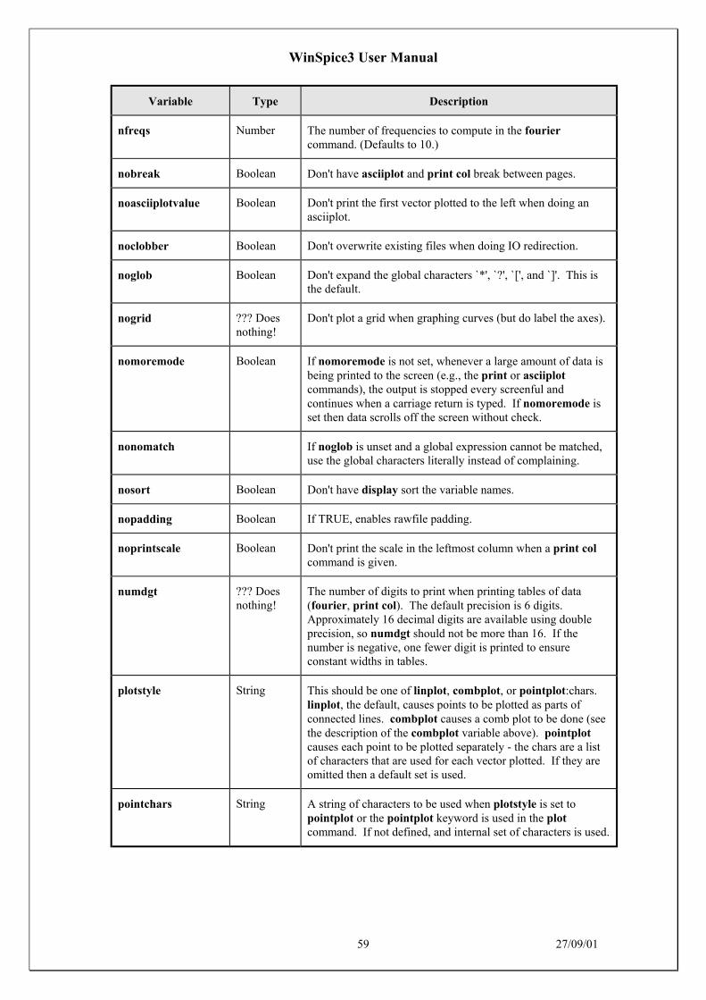
WinSpice3 User Manual
59 27/09/01
Variable Type Description
nfreqs Number The number of frequencies to compute in the fouriercommand. (Defaults to 10.)
nobreak Boolean Don't have asciiplot and print col break between pages.
noasciiplotvalue Boolean Don't print the first vector plotted to the left when doing anasciiplot.
noclobber Boolean Don't overwrite existing files when doing IO redirection.
noglob Boolean Don't expand the global characters `*', `?', `[', and `]'. This isthe default.
nogrid ??? Doesnothing!
Don't plot a grid when graphing curves (but do label the axes).
nomoremode Boolean If nomoremode is not set, whenever a large amount of data isbeing printed to the screen (e.g., the print or asciiplotcommands), the output is stopped every screenful andcontinues when a carriage return is typed. If nomoremode isset then data scrolls off the screen without check.
nonomatch If noglob is unset and a global expression cannot be matched,use the global characters literally instead of complaining.
nosort Boolean Don't have display sort the variable names.
nopadding Boolean If TRUE, enables rawfile padding.
noprintscale Boolean Don't print the scale in the leftmost column when a print colcommand is given.
numdgt ??? Doesnothing!
The number of digits to print when printing tables of data(fourier, print col). The default precision is 6 digits.Approximately 16 decimal digits are available using doubleprecision, so numdgt should not be more than 16. If thenumber is negative, one fewer digit is printed to ensureconstant widths in tables.
plotstyle String This should be one of linplot, combplot, or pointplot:chars.linplot, the default, causes points to be plotted as parts ofconnected lines. combplot causes a comb plot to be done (seethe description of the combplot variable above). pointplotcauses each point to be plotted separately - the chars are a listof characters that are used for each vector plotted. If they areomitted then a default set is used.
pointchars String A string of characters to be used when plotstyle is set topointplot or the pointplot keyword is used in the plotcommand. If not defined, and internal set of characters is used.

WinSpice3 User Manual
60 27/09/01
Variable Type Description
polydegree Number The degree of the polynomial that the plot command should fitto the data. If polydegree is N, then WinSpice3 fits a degree Npolynomial to every set of N points and draw 10 intermediatepoints in between each endpoint. If the points aren'tmonotonic, then it tries rotating the curve and reducing thedegree until a fit is achieved.
polysteps Number The number of points to interpolate between every pair ofpoints available when doing curve fitting. The default is 10.
printinfo ??? ???
program String The name of the current program (argv[0]).
prompt String The prompt, with the character `!' replaced by the current eventnumber.
rawfile String The default name for rawfiles created.
remote_shell String Overrides the name used for generating rspice runs (default is"rsh").
slowplot Boolean Stop between each graph plotted and wait for the user to typereturn before continuing.
sourcepath String A list of the directories to search when a source command isgiven. The default is the current directory and the standardSPICE library (/usr/local/lib/spice, or whatever LIBPATH is#defined to in the WinSpice3 source).
spicepath String The program to use for the aspice command. The default is/cad/bin/spice.
term String The mfb name of the current terminal.
ticmarks Number orBoolean
If this variable is defined with a numerical value n e.g. 'setticmarks=5', then every nth point on a plot is marked with acharacter.
If defined as a Boolean variable i.e. with no number supplied, aticmark is printed every 10 plot points.
ticdata ??? ???
units String If set to degrees, then all the trig functions will use degreesinstead of radians. This also means that the ph() operator forphase also give a phase angle in degrees.
unixcom Boolean If this variable is defined, the interactive command line willattempt to run a program with the same name.
Setting this option has the effect of giving a rehash command,below. This is useful for people who want to use WinSpice3as a login shell.
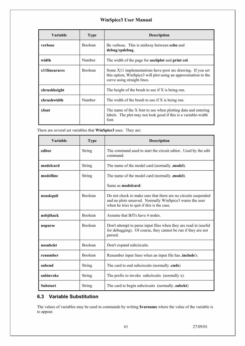
WinSpice3 User Manual
61 27/09/01
Variable Type Description
verbose Boolean Be verbose. This is midway between echo anddebug/cpdebug.
width Number The width of the page for asciiplot and print col.
x11lineararcs Boolean Some X11 implementations have poor arc drawing. If you setthis option, WinSpice3 will plot using an approximation to thecurve using straight lines.
xbrushheight The height of the brush to use if X is being run.
xbrushwidth Number The width of the brush to use if X is being run.
xfont The name of the X font to use when plotting data and enteringlabels. The plot may not look good if this is a variable-widthfont.
There are several set variables that WinSpice3 uses. They are:
Variable Type Description
editor String The command used to start the circuit editor.. Used by the editcommand.
modelcard String The name of the model card (normally .model).
modelline String The name of the model card (normally .model).
Same as modelcard.
noaskquit Boolean Do not check to make sure that there are no circuits suspendedand no plots unsaved. Normally WinSpice3 warns the userwhen he tries to quit if this is the case.
nobjthack Boolean Assume that BJTs have 4 nodes.
noparse Boolean Don't attempt to parse input files when they are read in (usefulfor debugging). Of course, they cannot be run if they are notparsed.
nosubckt Boolean Don't expand subcircuits.
renumber Boolean Renumber input lines when an input file has .include's.
subend String The card to end subcircuits (normally .ends)
subinvoke String The prefix to invoke subcircuits (normally x).
Substart String The card to begin subcircuits (normally .subckt)
6.3 Variable Substitution
The values of variables may be used in commands by writing $varname where the value of the variable isto appear.

WinSpice3 User Manual
62 27/09/01
The special variables $$ and $< refer to the process ID of the program and a line of input which is readfrom the terminal when the variable is evaluated, respectively.
If a variable has a name of the form $&word, then word is considered a vector (see above), and its value istaken to be the value of the variable.
If $foo is a valid variable, and is of type list, then the expression $foo[low-high] represents a range ofelements. Either the upper index or the lower may be left out, and the reverse of a list may be obtainedwith $foo[len-0]. Also, the notation $?foo evaluates to 1 if the variable foo is defined, 0 otherwise, and$#foo evaluates to the number of elements in foo if it is a list, 1 if it is a number or string, and 0 if it is aboolean variable.
6.4 Redirection
IO redirection is available in the same was as is found in the MSDOS and UNIX command shells asfollows:-
Description
> file Sends standard output to file. If the file already exists, it is truncated tozero length and its contents discarded. If it doesn't exist, it is created.
>> file Appends standard output to file. If the file already exists, the output isadded to the end of the file. If it doesn't exist, it is created.
>& file Sends standard output and standard error streams to file. If the filealready exists, it is truncated to zero length and its contents discarded. Ifit doesn't exist, it is created.
>>& Appends standard output and standard error streams to file. If the filealready exists, the output is added to the end of the file. If it doesn't exist,it is created.
< file Takes standard input from the file file
6.5 Vectors & Scalars
WinSpice3 data is in the form of vectors: time, voltage, etc. Each vector has a type, and vectors can beoperated on and combined algebraically in ways consistent with their types. Vectors are normally createdwhen a data file is read in (see the load command in section 6.12.25), and when the initial datafile isloaded. They can also be created with the let command (see section 6.12.22).
A scalar is a vector of length 1.
A vector may be either the name of a vector already defined or a floating-point number (a scalar). Anumber may be written in any format acceptable to SPICE, such as 14.6Meg or -1.231e-4. Note that youcan either use scientific notation or one of the abbreviations like MEG or G, but not both. As with SPICE,a number may have trailing alphabetic characters after it.
The notation expr [num] denotes the num'th element of expr. For multi-dimensional vectors, a vector ofone less dimension is returned. Also for multi-dimensional vectors, the notation expr[m][n] will return thenth element of the mth subvector. To get a subrange of a vector, use the form expr[lower, upper].
To reference vectors in a plot that is not the current plot (see the setplot command, below), the notationplotname.vecname can be used.

WinSpice3 User Manual
63 27/09/01
Either a plotname or a vector name may be the wildcard all. If the plotname is all, matching vectors fromall plots are specified, and if the vector name is all, all vectors in the specified plots are referenced.
Vector names in SPICE may have a name such as @name[param], where name is either the name of adevice instance or model. This denotes the value of the param parameter of the device or model. SeeAppendix B for details of what parameters are available. The value is a vector of length 1. This function isalso available with the show command, and is available with variables for convenience for commandscripts.
6.6 Expressions
An expression is an algebraic formula involving vectors and scalars and the following operations:
+ - * / ^ %
% is the modulo operator, and the comma operator has two meanings: if it is present in the argument list ofa user-definable function, it serves to separate the arguments. Otherwise, the term x , y is synonymous withx + j(y).
Also available are the logical operations & (and), | (or), ! (not), and the relational operations <, >, >=, <=,=, and <> (not equal). If used in an algebraic expression they work like they would in C, producing valuesof 0 or 1. The relational operators have the following synonyms:
gt >
lt <
ge >=
le <=
ne <>
eq =
and &
or |
not !
These are useful when < and > might be confused with IO redirection (which is almost always).
Note that you may not use binary operations on expressions involving wildcards - it is not obvious what all+ all should denote, for instance.
Thus some (contrived) examples of expressions are:
cos(TIME) + db(v(3))sin(cos(log([1 2 3 4 5 6 7 8 9 10])))TIME * rnd(v(9)) - 15 * cos(vin#branch) ^ [7.9e5 8]not ((ac3.FREQ[32] & tran1.TIME[10]) gt 3)
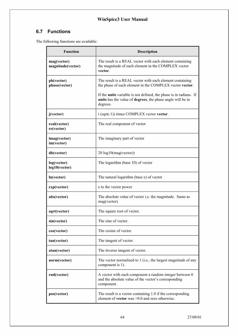
WinSpice3 User Manual
64 27/09/01
6.7 Functions
The following functions are available:
Function Description
mag(vector)magnitude(vector)
The result is a REAL vector with each element containingthe magnitude of each element in the COMPLEX vectorvector.
ph(vector)phase(vector)
The result is a REAL vector with each element containingthe phase of each element in the COMPLEX vector vector.
If the units variable is not defined, the phase is in radians. Ifunits has the value of degrees, the phase angle will be indegrees.
j(vector) i (sqrt(-1)) times COMPLEX vector vector.
real(vector)re(vector)
The real component of vector
imag(vector)im(vector)
The imaginary part of vector
db(vector) 20 log10(mag(vector))
log(vector)log10(vector)
The logarithm (base 10) of vector
ln(vector) The natural logarithm (base e) of vector
exp(vector) e to the vector power
abs(vector) The absolute value of vector i.e. the magnitude. Same asmag(vector).
sqrt(vector) The square root of vector.
sin(vector) The sine of vector.
cos(vector) The cosine of vector.
tan(vector) The tangent of vector.
atan(vector) The inverse tangent of vector.
norm(vector) The vector normalised to 1 (i.e., the largest magnitude of anycomponent is 1).
rnd(vector) A vector with each component a random integer between 0and the absolute value of the vector’s correspondingcomponent.
pos(vector) The result is a vector containing 1.0 if the correspondingelement of vector was >0.0 and zero otherwise.

WinSpice3 User Manual
65 27/09/01
Function Description
mean(vector) The result is a scalar (a length 1 vector) that is the mean ofthe elements of the vector.
sum(vector) The result is a scalar (a length 1 vector) that is the sum of theelements of the vector.
vector(number) The result is a vector of length number, with elements 0, 1,... number - 1. If number is a vector then just the firstelement is taken, and if it isn't an integer then the floor of themagnitude is used.
unitvec(vector) The result is a vector with each component set to 1.0. Thelength of the resultant vector is the value of the first numberin vector. If vector was complex, the length ismag(vector[0]).
length(vector) The result is a scalar (a length 1 vector) that is the length ofthe vector vector.
interpolate(plot.vector) The result of interpolating the named vector onto the scale ofthe current plot. This function uses the variable polydegreeto determine the degree of interpolation.
deriv(vector) Calculates the derivative of the given vector. This usesnumeric differentiation by interpolating a polynomial andmay not produce satisfactory results (particularly withiterated differentiation). The implementation only calculatesthe derivative with respect to the real component of thatvector's scale.

WinSpice3 User Manual
66 27/09/01
6.8 Constants
There are a number of pre-defined constants in WinSpice3 which can be used in expressions. They are:
Constant Description
true The value 1
yes The value 1
no The value 0
false The value 0
pi π (3.14159...)
e The base of natural logarithms (2.71828...)
c The speed of light (299,792,500 m/sec)
i The square root of –1 i.e. (0, 1)
kelvin Absolute 0 in Centigrade (-273.15 °C)
echarge The charge on an electron (1.6021918e-19 C)
boltz Boltzman's constant (1.3806226e-23)
planck Planck's constant (h = 6.626200e-34)
These are all in MKS units. If you have another variable with a name that conflicts with one of these thenit takes precedence.
6.9 History Substitutions
A history substitution enables you to reuse a portion of a previous command as you type the currentcommand. History substitutions save typing and also help reduce typing errors.
A history substitution normally starts with a ‘!’. A history substitution has three parts: an event thatspecifies a previous command, a selector that selects one or more word of the event, and some modifiersthat modify the selected words. The selector and modifiers are optional. A history substitution has theform
![event][[:]selector[:modifier] . . .]
The event is required unless it is followed by a selector that does not start with a digit. The ‘:’ can beomitted before selector if selector does not begin with a digit.
History substitutions are interpreted before anything else – even before quotations and commandsubstitutions. The only way to quote the ‘!’ of a history substitution is to escape it with a precedingbackslash. A ‘!’ need not be escaped , however, if it is followed by whitespace, ‘=’, or ‘(‘.
6.9.1 Events and Their Specifications
WinSpice3 saves each command that you type on a history list provided that the command contains at leastone word. The commands on the history list are called events. The events are numbered, with the firstcommand that you issue when you start WinSpice being number one. For complex commands such as‘for’ that consist of more than one line, only the first line makes its way to the history list. The history

WinSpice3 User Manual
67 27/09/01
variable specified how many events are retained on the history list. You can view the history list with thehistory command (see section 6.12.20 on Page 74).
These are the forms of an event in a history substitution:
!! The preceding event. Typing ‘!!’ is an easy way to reissue the previous command.
!n Event number n.
!-n The nth previous event. For example, ‘!-1’ refers to the immediately preceding event and isequivalent to ‘!!’.
!str The unique previous event whose name starts with str.
!?str? The unique previous event containing the string str. The closing ‘?’ can be omitted if it isfollowed by a newline.
6.9.2 Selectors
You can select a subset of the words of an event by attaching a selector to the event. A history substitutionwithout a selector includes all of the words of the event. These are the possible selectors for selectingwords of the event:
:0 The command name.
[:]^ The first argument.
[:]$ The last argument.
:n The nth argument (n ≥ 1)
:n1-n2 Words n1 through n2
[:]* Words 1 through $
:x* Words x through $
:x- Words x through ($ - 1)
[:]-x Words 0 through x
[:]% The word matched by the preceding ‘?str?’ search
The colon preceding a selector can be omitted if the selector does not start with a digit.
6.9.3 Modifiers
You can modify the words of an event by attaching one or more modifiers. Each modifier must bepreceded by a colon.
The following modifiers assume that the first selected word is a file name:
:r Removes the trailing ‘.str’ extension from the first selected word.
:h Removes a trailing path name component from the first selected word.
:t Removes all leading path name components from the first selected word.
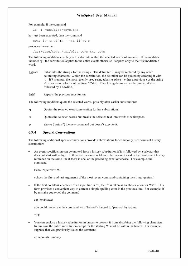
WinSpice3 User Manual
68 27/09/01
For example, if the command
ls –l /usr/elsa/toys.txt
has just been executed, then the command
echo !!^:r !!^:h !!^:t !!^:t:r
produces the output
/usr/else/toys /usr/elsa toys.txt toys
The following modifiers enable you to substitute within the selected words of an event. If the modifierincludes ‘g’, the substitution applies to the entire event; otherwise it applies only to the first modifiableword.
:[g]s/l/r Substitutes the string r for the string l. The delimiter ‘/’ may be replaced by any otherdelimiting character. Within the substitution, the delimiter can be quoted by escaping it with‘\’. If l is empty, the most recently used string takes its place – either a previous l or the stringstr in an event selector of the form ‘!?str?’. The closing delimiter can be omitted if it isfollowed by a newline.
:[g]& Repeats the previous substitution.
The following modifiers quote the selected words, possibly after earlier substitutions:
:q Quotes the selected words, preventing further substitutions.
:x Quotes the selected words but breaks the selected text into words at whitespace.
:p Shows (“prints”) the new command but doesn’t execute it.
6.9.4 Special Conventions
The following additional special conventions provide abbreviations for commonly used forms of historysubstitution:
• An event specification can be omitted from a history substitution if it is followed by a selector thatdoes not start with a digit. In this case the event is taken to be the event used in the most recent historyreference on the same line if there is one, or the preceding event otherwise. For example, thecommand
Echo !?quetzal?^ !$
echoes the first and last arguments of the most recent command containing the string ‘quetzal’.
• If the first nonblank character of an input line is ‘^’, the ‘^’ is taken as an abbreviation for ‘!:s^’. Thisform provides a convenient way to correct a simple spelling error in the previous line. For example, ifby mistake you typed the command
cat /etc/lasswd
you could re-execute the command with ‘lasswd’ changed to ‘passwd’ by typing
^l^p
• You can enclose a history substitution in braces to prevent it from absorbing the following characters.In this case the entire substitution except for the starting ‘!’ must be within the braces. For example,suppose that you previously issued the command
cp accounts ../money

WinSpice3 User Manual
69 27/09/01
Then the command ‘!cps’ looks for a previous command starting with ‘cps’ while the command‘!cps’ turns into a command
cp accounts ../moneys
6.10 Filename Expansions
The characters ~, , and have the same effects as they do in the C-Shell, i.e., home directory andalternative expansion. It is possible to use the wildcard characters *, ?, [, and ] also, but only if you unsetnoglob first. This makes them rather useless for typing algebraic expressions, so you should set noglobagain after you are done with wildcard expansion. Note that the pattern [^abc] matches all charactersexcept a, b, and c.
6.11 Control Structures
6.11.1 While - End
General Form
while condition statement ...end
While condition, an arbitrary algebraic expression, is true, execute the statements.
The condition is an expression involving vector and scalar variables (see sections 6.5 and 6.6).
For example, the following will sweep a resistor value:-
.controlecho ***********************************************************echo Sweep altering R1 directlyecho ***********************************************************let res = 1while res <= 100 alter @r1[resistance] = res op print v(1) v(2) let res = res + 5end.endc
6.11.2 Repeat - End
General Form
repeat [number] statement ...end
Execute the statements number times, or forever if no argument is given.
6.11.3 Dowhile - End
General Form
dowhile condition statement ...end
The same as while, except that the condition is tested after the statements are executed.
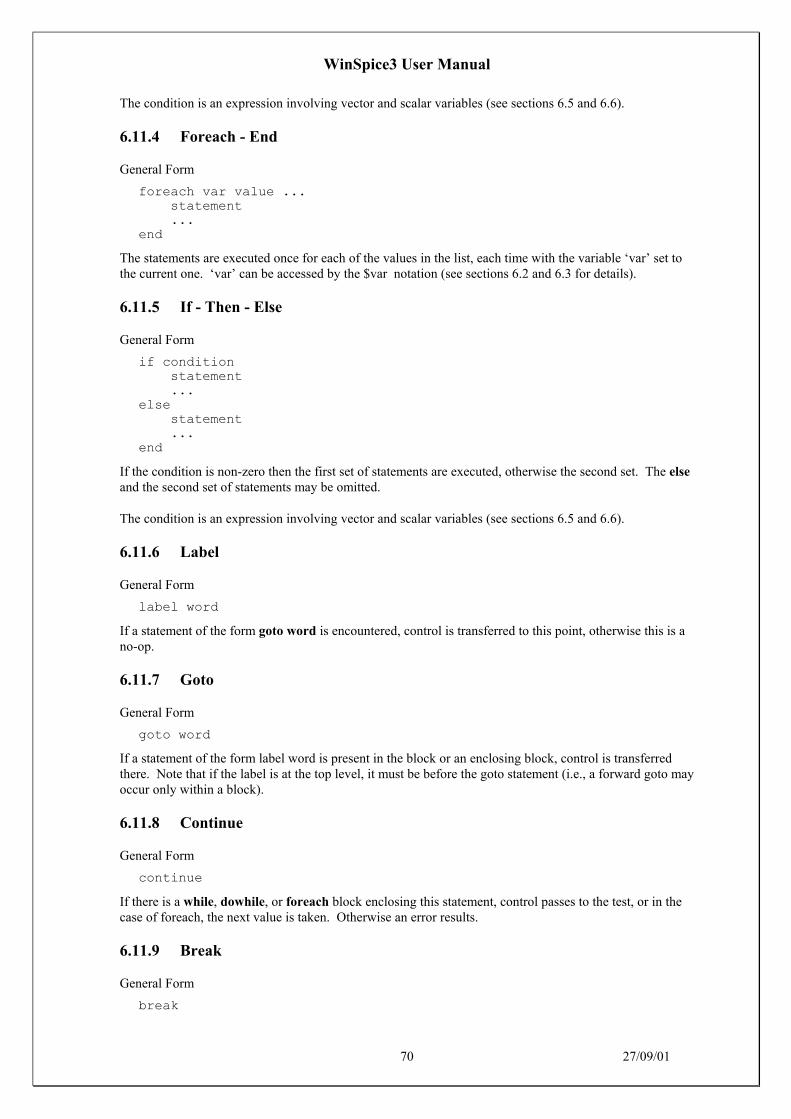
WinSpice3 User Manual
70 27/09/01
The condition is an expression involving vector and scalar variables (see sections 6.5 and 6.6).
6.11.4 Foreach - End
General Form
foreach var value ... statement ...end
The statements are executed once for each of the values in the list, each time with the variable ‘var’ set tothe current one. ‘var’ can be accessed by the $var notation (see sections 6.2 and 6.3 for details).
6.11.5 If - Then - Else
General Form
if condition statement ...else statement ...end
If the condition is non-zero then the first set of statements are executed, otherwise the second set. The elseand the second set of statements may be omitted.
The condition is an expression involving vector and scalar variables (see sections 6.5 and 6.6).
6.11.6 Label
General Form
label word
If a statement of the form goto word is encountered, control is transferred to this point, otherwise this is ano-op.
6.11.7 Goto
General Form
goto word
If a statement of the form label word is present in the block or an enclosing block, control is transferredthere. Note that if the label is at the top level, it must be before the goto statement (i.e., a forward goto mayoccur only within a block).
6.11.8 Continue
General Form
continue
If there is a while, dowhile, or foreach block enclosing this statement, control passes to the test, or in thecase of foreach, the next value is taken. Otherwise an error results.
6.11.9 Break
General Form
break

WinSpice3 User Manual
71 27/09/01
If there is a while, dowhile, or foreach block enclosing this statement, control passes out of the block.Otherwise an error results.
Of course, control structures may be nested. When a block is entered and the input is the terminal, theprompt becomes a number of >'s corresponding to the number of blocks the user has entered. The currentcontrol structures may be examined with the debugging command cdump.
6.12 Commands
6.12.1 Ac: Perform an AC frequency response analysis
General Form
ac ( DEC | OCT | LIN ) N Fstart Fstop
Do an AC analysis. See the previous sections of this manual for more details.
6.12.2 Alias: Create an alias for a command
General Form
alias [word] [text ...]
Causes word to be aliased to text. History substitutions may be used, as in C-shell aliases.
6.12.3 Alter: Change a device or model parameter
General Form
alter name = expressionalter name parameter = expressionalter @name[parameter] = expression
Alter changes the value for a device or a specified parameter of a device or model. The first form is usedby simple devices which have one principal value (resistors, capacitors, etc.) where the second and thirdforms are for more complex devices (BJTs, etc.).
If ‘name’ is the name of a device instance then the command will change a parameter within an individualdevice instance e.g.
alter @m1[temp] = 273
If ‘name’ is the name of a model then the command will change a model parameter and this will affect alldevice instances in the circuit which use this model e.g.
alter @nmos[lambda] = 3
For specifying vectors as expressions, start the vector with "[", followed by the values in the vector, andend with "]". Be sure to place a space between each of the values and before and after the "[" and "]".
6.12.4 Asciiplot: Plot values using old-style character plots
General Form
asciiplot plotargs
Produce a line printer plot of the vectors. The plot is sent to the standard output, so you can put it into a filewith asciiplot args ... > file. The set options width, height, and nobreak determine the width and height ofthe plot, and whether there are page breaks, respectively. Note that you will have problems if you try toasciiplot something with an X-scale that isn't monotonic (i.e., something like sin(TIME) ), because asciiplotuses a simple-minded linear interpolation.

WinSpice3 User Manual
72 27/09/01
6.12.5 Bug: Mail a bug report
General Form
bug
Send a bug report. Please include a short summary of the problem, the version number and name of theoperating system that you are running, the version of SPICE that you are running, and the relevant SPICEinput file. If you have defined BUGADDR, the mail is delivered to there.
NOTE: this command does not work yet – but it seems too useful to take out! Future versions ofWinSpice3 will use this command to email bug reports to the author.
6.12.6 Cd: Change directory
General Form
cd [directory]
Change the current working directory to directory. Displays the current directory if [directory] is not given.
6.12.7 Cross: Create a new vector
General Form
cross vecname n [vector1 vector2 ...]
Create a new vector vecname.from index n in each of the input vectors. n=0 selects the first item in eachvector. If any input vector is complex then the output vector will be complex.
The index value n may be a constant or a vector. If n is not scalar, only the first value in the vector is used.If n is a complex vector, only the real part is used.
This command can be used to get the nth value in a vector e.g.
cross val 5 v(3)
let index = 5cross val index v(3)
Both of the above are equivalent. The second example uses scalar vector ‘index’ to fetch the 6th item invector v(3).
6.12.8 Dc: Perform a DC-sweep analysis
General Form
dc Source-Name Vstart Vstop Vincr [Source2 Vstart2 Vstop2 Vincr2]
Do a DC transfer curve analysis. See the previous sections of this manual for more details.
6.12.9 Define: Define a function
General Form
define function(arg1, arg2, ...) expression
Define the user-definable function with the name function and arguments arg1, arg2, ... to be expression,which may involve the arguments. When the function is later used, the arguments it is given are substitutedfor the formal arguments when it is parsed. If expression is not present, any definition for function isprinted, and if there are no arguments to define then all currently active definitions are printed. Note thatyou may have different functions defined with the same name but different arities.
Some useful definitions are:

WinSpice3 User Manual
73 27/09/01
define max(x,y) (x > y) * x + (x <= y) * ydefine min(x,y) (x < y) * x + (x >= y) * y
6.12.10 Delete: Remove a trace or breakpoint
General Form
delete [ debug-number ... ]
Delete the specified breakpoints and traces. The debug-numbers are those shown by the status command(unless you do status > file, in which case the debug numbers are not printed).
6.12.11 Destroy: Delete a data set (plot)
General Form
destroy [plotnames | all]
Release the memory holding the data for the specified runs.
The command ‘destroy all’ also resets plot numbering back to 1 such that running an AC analysis, say, after‘destroy all’ always generates the ‘ac1’ plot vector. This is useful if .cir files contain plot lines whichaddress explicit plot names like ‘tran1.v(6)’ because if other circuits are run first then the plot numberingmay be changed.
6.12.12 Diff: Compare vectors
General Form
diff plot1 plot2 [vec ...]
Compare all the vectors in the specified plots, or only the named vectors if any are given. There aredifferent vectors in the two plots, or any values in the vectors differ significantly the difference is reported.The variable diff_abstol, diff_reltol, and diff_vntol are used to determine a significant difference.
6.12.13 Display: List known vectors and types
General Form
display [varname ...]
Prints a summary of currently defined vectors, or of the names specified. The vectors are sorted by nameunless the variable nosort is set. The information given is the name of the vector, the length, the type ofthe vector, and whether it is real or complex data. Additionally, one vector is labelled [scale]. When acommand such as plot is given without a vs argument, this scale is used for the X-axis. It is always thefirst vector in a rawfile, or the first vector defined in a new plot. If you undefine the scale (i.e., let TIME =[]), one of the remaining vectors becomes the new scale (which is undetermined).
6.12.14 Disto: Perform a distortion analysis
General Form
disto DEC ND FSTART FSTOP <F2OVERF1>disto OCT NO FSTART FSTOP <F2OVERF1>disto LIN NP FSTART FSTOP <F2OVERF1>
Examples:
disto dec 10 1kHz 100Mhzdisto dec 10 1kHz 100Mhz 0.9
The command line form of the .DISTO directive. See section 5.3.3 for details.

WinSpice3 User Manual
74 27/09/01
6.12.15 Echo: Print text
General Form
echo [text...]
Echoes the given text to the screen.
6.12.16 Edit: Edit the current circuit
General Form
edit [file]
Open the current WinSpice3 input file in the editor and allow the user to modify it. While the editor isrunning, WinSpice3 watches for the original file to be updated and, if so, reads the file back in. If afilename is given, then edit that file and load it, making the circuit the current one.
By default, Windows Notepad is used. This can be changed by setting the environment variable editor (seesection 6.2) e.g.
WinSpice3 18 -> set editor="c:\program files\accessories\wordpad.exe"WinSpice3 19 -> edit
6.12.17 Fourier: Perform a fourier transform
General Form
fourier fundamental_frequency [value ...]
Does a fourier analysis of each of the given values, using the first 10 multiples of the fundamentalfrequency (or the first nfreqs, if that variable is set - see below). The output is like that of the .fourWinSpice3 line. The values may be any valid expression. The values are interpolated onto a fixed-spacegrid with the number of points given by the fourgridsize variable, or 200 if it is not set. The interpolationis of degree polydegree if that variable is set, or 1. If polydegree is 0, then no interpolation is done. Thisis likely to give erroneous results if the time scale is not monotonic, though.
6.12.18 Hardcopy: Save a plot to a file for printing
General Form
hardcopy file plotargs
Just like plot, except creates a file called file containing the plot. The file is an image in plot(5) format, andcan be printed by either the plot(1) program or lpr with the -g flag.
6.12.19 Help: Print summaries of WinSpice3 commands
General Form
help [all] [command ...]
Prints help. If the argument ‘all’ is given, a short description of everything you could possibly type isprinted. If commands are given, descriptions of those commands are printed. Otherwise help for only afew major commands is printed.
6.12.20 History: Review previous commands
General Form
history [number]
Print out the history, or the last number commands typed at the keyboard.

WinSpice3 User Manual
75 27/09/01
6.12.21 Iplot: Incremental plot
General Form
iplot [node ...]
Example
iplot v(1) v(2)
Incrementally plot the values of the nodes while WinSpice3 runs. The iplot command can be used with thewhere command to find trouble spots in a transient simulation.
The iplot command adds a form of visual trace to the circuit. See the trace command (section 6.12.56) fora different type of trace that is available.
Several iplot commands may be active at once. Iplotting is not applicable for all analyses. To remove aniplot trace entry, use the delete command (see section 6.12.10). To display a list of iplots, use the statuscommand (see section 6.12.51).
6.12.22 Let: Assign a value to a vector
General Form
let name = expr
Creates a new vector called name with the value specified by expr, an expression as described above. Ifexpr is [] (a zero-length vector) then the vector becomes undefined. Individual elements of a vector maybe modified by appending a subscript to name (ex. name[0]).
A vector variable can be used within the scripting language like variables in other languages. Forexample:-
.control destroy all let ii = 0 while ii < 2 alter r1 = 10k + 10k * ii ac dec 10 1 10k let ii = ii + 1 end plot db(ac1.v(2)) db(ac2.v(2)).endcv1 1 0 dc 0 ac 1r1 1 2 1kc1 2 0 1uf.end
In the example shown, ‘ii’ is a single-element vector (scalar) used as a loop counter.
6.12.23 Linearize: Interpolate to a linear scale
General Form
linearize vec ...
Create a new plot with all of the vectors in the current plot, or only those mentioned if arguments are given.The new vectors are interpolated onto a linear time scale, which is determined by the values of tstep, tstart,and tstop in the currently active transient analysis. The currently loaded input file must include a transientanalysis (a tran command may be run interactively before the last reset, alternately), and the current plotmust be from this transient analysis.
This command is needed because WinSpice3 doesn't output the results from a transient analysis in thesame manner that SPICE2 did.

WinSpice3 User Manual
76 27/09/01
6.12.24 Listing: Print a listing of the current circuit
General Form
listing [logical] [physical] [deck] [expand]
If the logical argument is given, the listing is with all continuation lines collapsed into one line, and if thephysical argument is given the lines are printed out as they were found in the file. The default is logical. Adeck listing is just like the physical listing, except without the line numbers it recreates the input fileverbatim (except that it does not preserve case). If the word expand is present, the circuit is printed with allsubcircuits expanded.
6.12.25 Load: Load rawfile data
General Form
load [filename] ...
Loads either binary or ASCII format rawfile data from the files named. The default filename israwspice.raw, or the argument to the -r flag if there was one.
6.12.26 Noise: Perform a noise analysis
General Form
noise V(OUTPUT <,REF>) SRC ( DEC | LIN | OCT ) PTS FSTART FSTOP+ <PTS_PER_SUMMARY>
See section 5.3.4 for details of this command.
6.12.27 Op: Perform an operating point analysis
General Form
op
Do an operating point analysis. See section 5.3.5 of this manual for more details.
6.12.28 Plot: Plot values on the display
General Form
plot exprs [ylimit ylo yhi] [xlimit xlo xhi] [xindices xilo xihi][xcompress comp] [xdelta xdel] [ydelta ydel] [xlog] [ylog] [loglog][vs xname] [xlabel word] [ylabel word] [title word] [samep][linear] [linplot | combplot | pointplot]
Plot the given exprs on the screen (if you are on a graphics terminal). The xlimit and ylimit argumentsdetermine the high and low x- and y-limits of the axes, respectively. The xindices arguments determinewhat range of points are to be plotted - everything between the xilo'th point and the xihi'th point is plotted.The xcompress argument specifies that only one out of every comp points should be plotted. If an xdeltaor a ydelta parameter is present, it specifies the spacing between grid lines on the X- and Y-axis. Theseparameter names may be abbreviated to xl, yl, xind, xcomp, xdel, and ydel respectively.
The xname argument is an expression to use as the scale on the x-axis. If xlog or ylog are present then theX or Y scale, respectively, is logarithmic (loglog is the same as specifying both). The xlabel and ylabelarguments cause the specified labels to be used for the X and Y axes, respectively.
If samep is given, the values of the other parameters (other than xname) from the previous plot, hardcopy,or asciiplot command is used unless re-defined on the command line.
The title argument is used in the place of the plot name at the bottom of the graph.

WinSpice3 User Manual
77 27/09/01
The linear keyword is used to override a default log-scale plot (as in the output for an AC analysis).
Different styles of plot can be selected via the linplot, pointplot and combplot keywords. Specifyinglinplot gives a plot where each point is connected to the next by a line. If pointplot is used, the points arerepresented by a character with no joining lines. The combplot is drawn with a vertical line from eachpoint to the X-axis. The plot type can also be specified via the plotstyle variable e.g. 'setplotstyle=combplot'. The if a plot style is given in the plot command, this overrides the variable.
Finally, the keyword polar to generate a polar plot. To produce a smith plot, use the keyword smith. Notethat the data is transformed, so for smith plots you will see the data transformed by the function (x-1)/(x+1). To produce a polar plot with a smith grid but without performing the smith transform, use thekeyword smithgrid.
6.12.29 Print: Print values
General Form
print [col] [line] expr ...
Prints the vector described by the expression expr. If the col argument is present, print the vectors namedside by side. If line is given, the vectors are printed horizontally. col is the default, unless all the vectorsnamed have a length of one, in which case line is the default. The options width, length, and nobreak areeffective for this command (see asciiplot). If the expression is all, all of the vectors available are printed.Thus print col all > file prints everything in the file in SPICE2 format. The scale vector (time, frequency)is always in the first column unless the variable noprintscale is true.
6.12.30 Pz: Perform a Pole-Zero Analysis
General Form
pz NODE1 NODE2 NODE3 NODE4 CUR POLpz NODE1 NODE2 NODE3 NODE4 CUR ZERpz NODE1 NODE2 NODE3 NODE4 CUR PZpz NODE1 NODE2 NODE3 NODE4 VOL POLpz NODE1 NODE2 NODE3 NODE4 VOL ZERpz NODE1 NODE2 NODE3 NODE4 VOL PZ
Examples:
pz 1 0 3 0 CUR POLpz 2 3 5 0 VOL ZERpz 4 1 4 1 CUR PZ
CUR stands for a transfer function of the type (output voltage)/(input current) while VOL stands for atransfer function of the type (output voltage)/(input voltage). POL stands for pole analysis only, ZER forzero analysis only and PZ for both. This feature is provided mainly because if there is a non-convergencein finding poles or zeros, then, at least the other can be found. Finally, NODE1 and NODE2 are the twoinput nodes and NODE3 and NODE4 are the two output nodes. Thus, there is complete freedom regardingthe output and input ports and the type of transfer function.
6.12.31 Quit: Leave WinSpice3
General Form
quit
Quit WinSpice3.

WinSpice3 User Manual
78 27/09/01
6.12.32 Rawfile: Send further results directly to a rawfile
General Form
rawfile [rawfile][OFF]
Send the output of subsequent analyses directly to a file. ‘rawfile off’ restores default operation.
6.12.33 Reset: Reset an analysis
General Form
reset
Throw out any intermediate data in the circuit (e.g., after a breakpoint or after one or more analyses havebeen done already), and re-parse the input file. The circuit can then be re-run from it's initial state,overriding the affect of any set or alter commands. In SPICE-3e and earlier versions this was doneautomatically by the run command.
6.12.34 Reshape: Alter the dimensionality or dimensions of a vector
General Form
reshape vector vector ...
or
reshape vector vector ... [ dimension, dimension, ... ]
or
reshape vector vector ... [ dimension ][ dimension ] ...
This command changes the dimensions of a vector or a set of vectors. The final dimension may be left offand it will be filled in automatically. If no dimensions are specified, then the dimensions of the first vectorare copied to the other vectors. An error message of the form 'dimensions of x were inconsistent' can beignored.
6.12.35 Resume: Continue a simulation after a stop
General Form
resume
Resume a simulation after a stop or interruption (control-C).
6.12.36 Run: Run analysis from the input file
General Form
run [rawfile]
Run the simulation loaded by a previous ‘source’ command. If there were any of the control lines .ac, .op,.tran, or .dc, they are executed.
The output is put in rawfile if it was given, in addition to being available interactively.
6.12.37 Rusage: Resource usage
General Form
rusage [resource ...]
Print resource usage statistics. If any resources are given, just print the usage of that resource. Mostresources require that a circuit be loaded.

WinSpice3 User Manual
79 27/09/01
Currently valid resources are:-
Item Description
elapsed The amount of time elapsed since the last rusage elapsed call.
faults Number of page faults and context switches (BSD only).
space Data space used.
time CPU time used so far.
temp Operating temperature.
tnom Temperature at which device parameters were measured.
equations Circuit Equations
time Total Analysis Time
totiter Total iterations
accept Accepted timepoints
rejected Rejected timepoints
loadtime Time spent loading the circuit matrix and RHS.
reordertime Matrix reordering time
lutime L-U decomposition time
solvetime Matrix solve time
trantime Transient analysis time
tranpoints Transient timepoints
traniter Transient iterations
trancuriters Transient iterations for the last time point*
tranlutime Transient L-U decomposition time
transolvetime Transient matrix solve time
everything All of the above.
* listed incorrectly as "Transient iterations per point".

WinSpice3 User Manual
80 27/09/01
6.12.38 Save: Save a set of output vectors
General Form
save [all | vector vector ...]
Examples:
save i(vin) input outputsave @m1[id]
Save a set of output vectors, discarding the rest. If a vector has been mentioned in a save command, itappears in the working plot after a run has completed, or in the rawfile if SPICE is run in batch mode. If avector is traced or plotted (see below) it is also saved.
For backward compatibility, if there are no save commands given, all outputs are saved.
When the keyword ‘all’ appears in the save command, all default values (node voltages and voltage sourcecurrents) are saved in addition to any other values listed.
6.12.39 Sens: Run a sensitivity analysis
General Form
sens output_variablesens output_variable ac ( DEC | OCT | LIN ) N Fstart Fstop
Perform a Sensitivity analysis. output_variable is either a node voltage (ex. "v(1)" or "v(A,out)") or acurrent through a voltage source (ex. "i(vtest)"). The first form calculates DC sensitivities, the secondform calculates AC sensitivities. The output values are in dimensions of change in output per unit changeof input (as opposed to percent change in output or per percent change of input).
6.12.40 Set: Set the value of a variable
General Form
set [word]set [word = value] ...
Set the value of word to be value, if it is present. You can set any word to be any value, numeric or string.If no value is given then the value is the boolean 'true'.
The value of word may be inserted into a command by writing $word. If a variable is set to a list of valuesthat are enclosed in parentheses (which must be separated from their values by white space), the value ofthe variable is the list.
The variables used by WinSpice3 are listed in section 6.2.
6.12.41 Setcirc: Change the current circuit
General Form
setcirc [circuit name]
The current circuit is the one that is used for the simulation commands below. When a circuit is loadedwith the source command (see below) it becomes the current circuit.
WinSpice3 maintains a list of circuits which have been loaded into the system. The length of this list isdefined by the value of the environment variable maxcircuits which, to conserve memory, is set to 1 bydefault.

WinSpice3 User Manual
81 27/09/01
6.12.42 Setplot: Switch the current set of vectors
General Form
setplot [plotname]
Set the current plot to the plot with the given name, or if no name is given, prompt the user with a menu.(Note that the plots are named as they are loaded, with names like tran1 or op2. These names are shown bythe setplot and display commands and are used by diff, below.) If the "New plot" item is selected, thecurrent plot becomes one with no vectors defined.
Note that here the word "plot" refers to a group of vectors that are the result of one SPICE run. When morethan one file is loaded in, or more than one plot is present in one file, WinSpice3 keeps them separate andonly shows you the vectors in the current plot.
6.12.43 Setscale: Set the scale for a plot
General Form
setscale [vector]
Changes the scale vector for the current plot. If ‘vector’ is not given, this comment displays the scale forthe plot.

WinSpice3 User Manual
82 27/09/01
6.12.44 Settype: Set the type of a vector
General Form
settype type vector ...
Change the type of the named vectors to type. The available type names are as follows:-
type Units shown on plots
notype None
time “S”
frequency “Hz”
voltage "V"
current "A"
onoise-spectrum "(V or A)^2/Hz"
onoise-integrated "V or A"
inoise-spectrum "(V or A)^2/Hz"
inoise-integrated "V or A"
output-noise None
input-noise None
pole None
Zero None
s-param None
impedance "Ohms"
admittance "Mhos"
power "W"
phase "Degrees" or “Radians”
decibel "dB"
6.12.45 Shell: Call the command interpreter
General Form
shell [command]
Call the operating system's command interpreter; execute the specified command or call for interactive use.

WinSpice3 User Manual
83 27/09/01
6.12.46 Shift: Alter a list variable
General Form
shift [varname] [number]
If varname is the name of a list variable, it is shifted to the left by number elements (i.e., the numberleftmost elements are removed). The default varname is argv, and the default number is 1.
6.12.47 Show: List device state
General Form
showshow devs : paramsshow devs : params ; devs : paramsshow dev dev dev : param param param , dev dev : param paramshow t : param param param, t : param param
The show command prints out tables summarising the operating condition of selected devices (much likethe SPICE2 operation point summary).
• If device is missing, a default set of devices are listed.
• If device is a single letter, devices of that type are listed.
• If device is a subcircuit name (beginning and ending in ":") only devices in that subcircuit areshown (end the name in a double-":" to get devices within sub-subcircuits recursively).
The second and third forms may be combined ("letter:subcircuit:") or "letter:subcircuit::") to select aspecific type of device from a subcircuit. A device's full name may be specified to list only that device.Finally, devices may be selected by model by using the form "#modelname" or":subcircuit#modelname" or "letter:subcircuit#modelname".
If no parameters are specified, the values for a standard set of parameters are listed. If the list of parameterscontains a "+", the default set of parameters is listed along with any other specified parameters.
For both devices and parameters, the word "all" has the obvious meaning. For example
show all : all
shows all output parameters in all devices.
Note: there must be spaces separating the ":" that divides the device list from the parameter list.
6.12.48 Showmod: List model parameter values
General Form
showmod models [:parameters] , ...
The showmod command operates like the show command (above) but prints out model parameter values.The applicable forms for models are a single letter specifying the device type letter, "letter:subckt:","modelname", ":subckt:modelname", or "letter:subcircuit:modelname".
6.12.49 Source: Read a WinSpice3 input file
General Form
source file
For WinSpice3: Read the WinSpice3 input file.
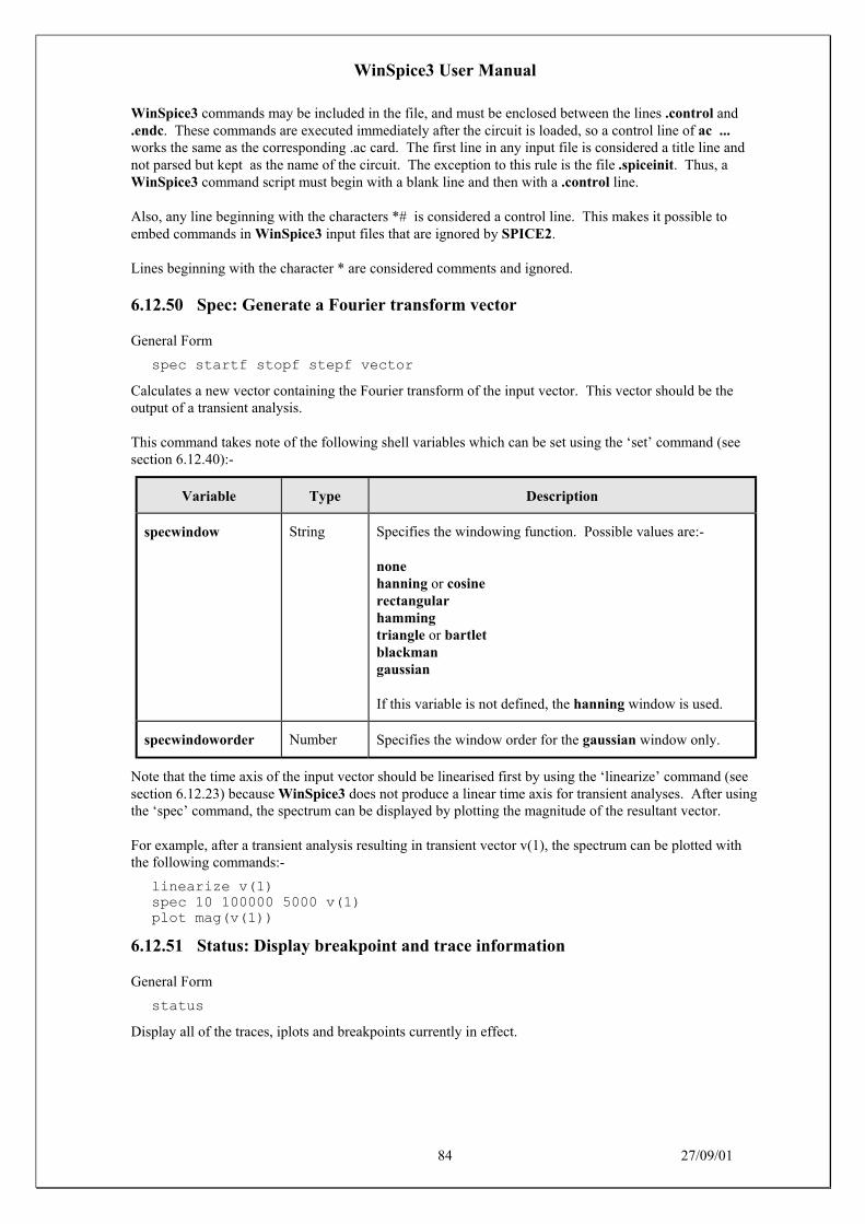
WinSpice3 User Manual
84 27/09/01
WinSpice3 commands may be included in the file, and must be enclosed between the lines .control and.endc. These commands are executed immediately after the circuit is loaded, so a control line of ac ...works the same as the corresponding .ac card. The first line in any input file is considered a title line andnot parsed but kept as the name of the circuit. The exception to this rule is the file .spiceinit. Thus, aWinSpice3 command script must begin with a blank line and then with a .control line.
Also, any line beginning with the characters *# is considered a control line. This makes it possible toembed commands in WinSpice3 input files that are ignored by SPICE2.
Lines beginning with the character * are considered comments and ignored.
6.12.50 Spec: Generate a Fourier transform vector
General Form
spec startf stopf stepf vector
Calculates a new vector containing the Fourier transform of the input vector. This vector should be theoutput of a transient analysis.
This command takes note of the following shell variables which can be set using the ‘set’ command (seesection 6.12.40):-
Variable Type Description
specwindow String Specifies the windowing function. Possible values are:-
nonehanning or cosinerectangularhammingtriangle or bartletblackmangaussian
If this variable is not defined, the hanning window is used.
specwindoworder Number Specifies the window order for the gaussian window only.
Note that the time axis of the input vector should be linearised first by using the ‘linearize’ command (seesection 6.12.23) because WinSpice3 does not produce a linear time axis for transient analyses. After usingthe ‘spec’ command, the spectrum can be displayed by plotting the magnitude of the resultant vector.
For example, after a transient analysis resulting in transient vector v(1), the spectrum can be plotted withthe following commands:-
linearize v(1)spec 10 100000 5000 v(1)plot mag(v(1))
6.12.51 Status: Display breakpoint and trace information
General Form
status
Display all of the traces, iplots and breakpoints currently in effect.

WinSpice3 User Manual
85 27/09/01
6.12.52 Step: Run a fixed number of time points
General Form
step [number]
Iterate number times, or once, and then stop.
6.12.53 Stop: Set a breakpoint
General Form
stop [after n] [when value cond value] ...
Set a breakpoint. The argument after n means stop after n iteration number n, and the argument whenvalue cond value means stop when the first value is in the given relation with the second value, thepossible relations being
eq or = equal to
ne or <> not equal to
gt or > greater than
lt or < less than
ge or >= greater than or equal to
le or <= less than or equal to
I/O redirection is disabled for the stop command, since the relational operations conflict with it (it doesn'tproduce any output anyway). The values above may be node names in the running circuit, or real values.If more than one condition is given, e.g. stop after 4 when v(1) > 4 when v(2) < 2, the conjunction of theconditions is implied.
6.12.54 Strcmp: Compare strings
General Form
strcmp res var1 var2
Example
strcmp i $resp newif $i = 0 set curplot = new goto bottomend
Compare two string variables var1 and var2 for equality and set variable res as follows:-
0 if they are equal–1 if var1 < var2+1 if var1 > var2
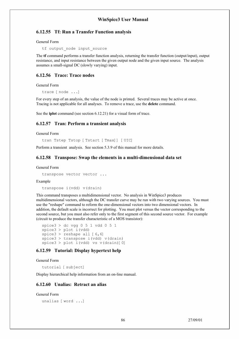
WinSpice3 User Manual
86 27/09/01
6.12.55 Tf: Run a Transfer Function analysis
General Form
tf output_node input_source
The tf command performs a transfer function analysis, returning the transfer function (output/input), outputresistance, and input resistance between the given output node and the given input source. The analysisassumes a small-signal DC (slowly varying) input.
6.12.56 Trace: Trace nodes
General Form
trace [node ...]
For every step of an analysis, the value of the node is printed. Several traces may be active at once.Tracing is not applicable for all analyses. To remove a trace, use the delete command.
See the iplot command (see section 6.12.21) for a visual form of trace.
6.12.57 Tran: Perform a transient analysis
General Form
tran Tstep Tstop [Tstart [Tmax]] [UIC]
Perform a transient analysis. See section 5.3.9 of this manual for more details.
6.12.58 Transpose: Swap the elements in a multi-dimensional data set
General Form
transpose vector vector ...
Example
transpose i(vdd) v(drain)
This command transposes a multidimensional vector. No analysis in WinSpice3 producesmultidimensional vectors, although the DC transfer curve may be run with two varying sources. You mustuse the "reshape" command to reform the one-dimensional vectors into two dimensional vectors. Inaddition, the default scale is incorrect for plotting. You must plot versus the vector corresponding to thesecond source, but you must also refer only to the first segment of this second source vector. For example(circuit to produce the transfer characteristic of a MOS transistor):
spice3 > dc vgg 0 5 1 vdd 0 5 1spice3 > plot i(vdd)spice3 > reshape all [6,6]spice3 > transpose i(vdd) v(drain)spice3 > plot i(vdd) vs v(drain)[0]
6.12.59 Tutorial: Display hypertext help
General Form
tutorial [subject]
Display hierarchical help information from an on-line manual.
6.12.60 Unalias: Retract an alias
General Form
unalias [word ...]

WinSpice3 User Manual
87 27/09/01
Removes any aliases present for the words.
6.12.61 Undefine: Retract a definition
General Form
undefine function
Definitions for the named user-defined functions are deleted.
6.12.62 Unlet: Delete vectors
General Form
unlet varname ...
Delete one or more vectors.
6.12.63 Unset: Clear a variable
General Form
unset [word ...]
Clear the value of the specified variable(s) (word).
6.12.64 Version: Print the version of WinSpice
General Form
version [version id]
Print out the version of WinSpice that is running. If there are arguments, it checks to make sure that thearguments match the current version of WinSpice.
6.12.65 Where: Identify troublesome node or device
General Form
where
When performing a transient or operating point analysis, the name of the last node or device to cause non-convergence is saved. The where command prints out this information so that you can examine the circuitand either correct the problem or make a bug report. You may do this either in the middle of a run or afterthe simulator has given up on the analysis. For transient simulation, the iplot command can be used tomonitor the progress of the analysis. When the analysis slows down severely or hangs, interrupt thesimulator (with control-C) and issue the where command. Note that only one node or device is printed;there may be problems with more than one node.
6.12.66 Write: Write data to a file
General Form
write [file [exprs]]
Writes out the expressions to file.
First vectors are grouped together by plots, and written out as such (i.e. if the expression list containedthree vectors from one plot and two from another, then two plots are written, one with three vectors andone with two). Additionally, if the scale for a vector isn't present, it is automatically written out as well.
The default format is ASCII, but this can be changed with the set filetype command. The default filenameis rawspice.raw, or the argument to the -r flag on the command line, if there was one, and the defaultexpression list is all.

WinSpice3 User Manual
88 27/09/01
If file is given and it has the file extension ‘.csv’, the file will be written as ASCII in comma separatedvalue format.
6.13 Miscellaneous
If there are subcircuits in the input file, WinSpice3 expands instances of them. A subcircuit is delimited bythe cards .subckt and .ends, or whatever the value of the variables substart and subend is, respectively.An instance of a subcircuit is created by specifying a device with type 'x' - the device line is written
xname node1 node2 ... subcktname
where the nodes are the node names that replace the formal parameters on the .subckt line. All nodes thatare not formal parameters are prepended with the name given to the instance and a ':', as are the names ofthe devices in the subcircuit. If there are several nested subcircuits, node and device names look likesubckt1:subckt2:...:name. If the variable subinvoke is set, then it is used as the prefix that specifiesinstances of subcircuits, instead of 'x'.
WinSpice3 occasionally checks to see if it is getting close to running out of space, and warns the user ifthis is the case.
6.14 Bugs
When defining aliases like
alias pdb plot db( '!:1' - '!:2' )
you must be careful to quote the argument list substitutions in this manner. If you quote the wholeargument it might not work properly.
In a user-defined function, the arguments cannot be part of a name that uses the plot.vec syntax. Forexample:
define check(v(1)) cos(tran1.v(1))
does not work.
If you type plot all all, or otherwise use a wildcard reference for one plot twice in a command, the effect isunpredictable.
The asciiplot command doesn't deal with log scales or the delta keywords.
WinSpice3 recognises all the notations used in SPICE2 .plot cards, and translates vp(1) into ph(v(1)), andso forth. However, if there are spaces in these names it won't work. Hence v(1, 2) and (-.5, .5) aren'trecognised.
BJTs can have either 3 or 4 nodes, which makes it difficult for the subcircuit expansion routines to decidewhat to rename. If the fourth parameter has been declared as a model name, then it is assumed that thereare 3 nodes, otherwise it is considered a node. To disable this, you can set the variable nobjthack whichforces BJTs to have 4 nodes (for the purposes of subcircuit expansion, at least).
The @name[param] notation might not work with trace, iplot, etc. yet.
The first line of a command file (except for the .spiceinit file) should be a comment, otherwise WinSpice3may create an empty circuit.
Files specified on the command line are read before .spiceinit is read.

WinSpice3 User Manual
89 27/09/01
7 CONVERGENCE
Both DC and transient solutions are obtained by an iterative process, which is terminated when both of thefollowing conditions hold:
• The non-linear branch currents converge to within a tolerance of 0.1% or 1 picoamp (1.0e-12Amp), whichever is larger.
• The node voltages converge to within a tolerance of 0.1% or 1 microvolt (1.0e-6 Volt),whichever is larger.
Although the algorithm used in SPICE has been found to be very reliable, in some cases it fails to convergeto a solution. When this failure occurs, the program terminates the job.
Failure to converge in DC analysis is usually due to an error in specifying circuit connections, elementvalues, or model parameter values. Regenerative switching circuits or circuits with positive feedbackprobably will not converge in the DC analysis unless the OFF option is used for some of the devices in thefeedback path, or the .NODESET control line is used to force the circuit to converge to the desired state.
7.1 Solving Convergence Problems
The following techniques on solving convergence problems are taken from various sources including:
1. Meares, L.G., Hymowitz C.E. "Simulating With Spice", Intusoft, 1988
2. Muller, K.H. "A SPICE Cookbook", Intusoft, 1990
3. Meares, L.G., Hymowitz C.E. "Spice Applications Handbook", Intusoft, 1990
4. Intusoft Newsletters, various dates from 1986 to present.
5. Quarles, T. L., "Analysis of Performance and Convergence Issues for Circuit Simulation",U.C.Berkeley, ERL Memo M89/42, April 1989.
7.2 What is Convergence? (or Non-Convergence!)
The answer to a non-linear problem, such as those in the SPICE DC and Transient analyses, is found via aniterative solution. For example, WinSpice3 makes an initial guess at the circuit's node voltages and then,using the circuit conductances, finds the mesh currents. The currents are then used to recalculate the nodevoltages and the cycle begins again. This continues until all of the node voltages settle to within certaintolerance limits, which can be altered using various .OPTIONS parameters such as RELTOL, VNTOL, andABSTOL.
If the node voltages do not settle down within a certain number of iterations, the DC analysis will issue anerror message, such as "No convergence in DC analysis", "PIVTOL Error", "Singular Matrix", or"Gmin/Source Stepping Failed". SPICE will then terminate the run because both the AC and transientanalyses require an initial stable operating point in order to start. During the transient analysis, thisiterative process is repeated for each individual time step. If the node voltages do not settle down, the timestep is reduced and SPICE tries again to determine the node voltages. If the time step is reduced beyond acertain fraction of the total analysis time, the transient analysis will issue an error message ("Time step toosmall") and the analysis will be halted.
Solutions to the DC analysis may fail to converge because of incorrect initial voltage guesses, modeldiscontinuities, unstable/bistable operation, or unrealistic circuit impedances. Transient analysis failuresare usually due to model discontinuities or unrealistic circuit, source, or parasitic modelling. The varioussolutions to convergence problems fall under one of two types. Some are simply Band-Aids. That is, they

WinSpice3 User Manual
90 27/09/01
merely try to fix the symptom by adjusting the simulator options. While other solutions actually effect thereal cause of the convergence problems.
The following techniques can be used to solve 90-95% of all convergence problems. When a convergenceproblem is encountered you should start at solution 1 and continue on with the subsequent fixes untilconvergence is achieved. The order of the solutions is set-up so those lower number fixes can be left in thesimulation as additional fixes are added. The order is also set-up so that the initial fixes will be of the mostbenefit. The user should note that fixes involving simulation options might simply mask the underlyingcircuit instabilities. Invariably, the user will find that once the circuit is properly modelled, many of the"options" fixes will no longer be required!
7.3 SPICE3 - New Convergence Algorithms
In addition to automatically invoking the traditional source stepping algorithm, SPICE3 contains a newsuperior algorithm called "Gmin Stepping". This algorithm uses a constant minimal junction conductanceto keep the sparse matrix well conditioned and a separate variable conductance to ground at each node as aDC convergence aid. These variable conductances make the solution converge faster, they are thenreduced and the solution re-computed. Eventually, the solution is found with a sufficiently smallconductance. Finally, the conductance is removed entirely to obtain a final solution. This technique hasbeen found to work very well and SPICE3 uses it by default when convergence problems occur. Thesuggestion, made in a number of textbooks, of reducing the .OPTIONS GMIN value in order to solveconvergence problems is performed automatically by this new algorithm.
7.4 Non-Convergence Error Messages/Indications
DC Analysis (.OP, small signal bias solution before the AC analysis or Initial transientsolution before the Transient analysis) - "No Convergence in DC analysis","PIVTOL Error". WinSpice3 programs will issue "Gmin/Source SteppingFailed" or "Singular Matrix" messages.
DC SWEEP Analysis(.DC)
"No Convergence in DC analysis at Step = xxx"
Transient (.TRAN) "Internal timestep too small"
IMPORTANT NOTE: The suggestions listed below are applicable to most SPICE programs, especially ifthey are Berkeley SPICE compatible.
7.5 Convergence Solutions
7.5.1 DC Convergence Solutions
1. Check the circuit topology and connectivity.
.OPTIONS NODE LIST will provide a nice summary print out of the nodal connections.
Common mistakes:
• Make sure all of the circuit connections are valid. Check for incorrect node numbering ordangling nodes
• Make sure you didn't use the letter O instead of a zero (0)
• Check for syntax mistakes. Make sure you used the correct SPICE units (MEG instead of Mfor 1E6)
• Check for a DC path to ground from every node

WinSpice3 User Manual
91 27/09/01
• Ensure that there are two connections at each node
• No loops of inductors or voltage sources
• No series capacitors or current sources
• Have ground (node 0) somewhere in the circuit. Be careful when using floating grounds; alarge valued resistor connected from the floating point to ground may be needed
• Check to see that voltage/current generators are at their proper values
• Check to see that dependent source gains are correct
• Check for realistic model parameters; especially if you copied the model into the netlist byhand
• Check to see that all resistors have a value. In WinSpice3 resistors without values are givena default of 1KOhm
2. Increase ITL1 to 300 in the .OPTIONS statement.
Example: .OPTIONS ITL1=300
Increases the number of DC iterations WinSpice3 will go through before giving up. Further increases inITL1, in all but the most complex circuits, will not usually yield convergence.
3. Set ITL6 =100 in the .OPTIONS statement.
Example: .OPTIONS ITL6=100
Invokes the source stepping algorithm. 100 are the number of steps used. This solution is unnecessary forWinSpice3 users as source stepping is automatically invoked after both the default method and the newGmin stepping algorithms have been tried. Note for SPICE2 users, this is an undocumented BerkeleySPICE2 option.
4. Add .NODESETs
Example:
NODESET V(6)=0
Check the node voltage table in the output file. Add .NODESETS statements to nodes that SPICE sayshave unrealistic or way out voltages. Use a .NODESET of 0V if you do not have a better estimation of theproper DC voltage.
5. Add resistors and use the OFF keyword
Example:
D1 1 2 DMOD OFFRD1 1 2 100MEG
Add resistors across diodes to simulate leakage and resistors across MOSFET drain to source connectionsto simulate realistic channel impedances. Add ohmic resistances (RC, RB, and RE) to transistors. ReduceGmin an order of magnitude in the .OPTIONS statement. Add the OFF keyword to semiconductors(especially diodes) that may be causing convergence problems. The OFF keyword tells WinSpice3 to firstsolve the operating point with the device off. Then, the device is turned on and the previously foundoperating point is used as a starting condition for the final operating point.
6. Change DC power supplies into PULSE statements.

WinSpice3 User Manual
92 27/09/01
Example:
From
VCC 1 0 15 DC
To
VCC 1 0 PULSE 0 15
This allows the user to selectively turn on certain power supplies just like in real life. This is sometimesknown as the "Pseudo-Transient" method. Use a reasonable rise time in the PULSE statement to simulaterealistic turn on, for example,
V1 1 0 PULSE 0 5 0 1U would provide a 5 volt supply with a turn on of 1 microsecond. The first valueafter the 5 voltage (in this case 0) is the turn-on delay that can be used to let the circuit settle down beforeturning on the power supply.
7. UIC
Example:
.TRAN .1N 100N UIC
Insert the UIC keyword in the .TRAN statement. UIC means Use Initial Conditions. UIC will causeWinSpice3 to completely by-pass the DC analysis. You should add any applicable .IC and IC= initialconditions statements to assist in the initial stages of the transient analysis. Note: this solution is not viablewhen you want to perform an AC analysis because the AC analysis must be proceeded by an operatingpoint.
AC Analysis Note: Solutions 5 and 6 should be used as a last resort because they will not produce a validDC operating point for the circuit (All supplies turned ON). However, if your aim is to get to the transientanalysis, then solutions 5 and 6 may help you get there and possibly uncover the hidden problems plaguingthe DC analysis along the way.
7.5.2 DC Sweep Convergence Solutions
1. Check circuit topology and connectivity
This is the same as 0 in DC analysis.
Set ITL2=100 in the .OPTIONS statement
Example:
.OPTIONS ITL2=100
Increases the number of DC iterations WinSpice3 will go through before giving up.
2. Make the steps in the .DC sweep larger or smaller
Example: From
.DC VCC 0 1 .1
To
.DC VCC 0 1 .01
Discontinuities in the SPICE models can cause convergence problems. Larger steps can help to bypass thediscontinuities while smaller steps can help WinSpice3 find the intermediate answers that will be used tofind non-converging point.
3. Do not use the DC sweep analysis

WinSpice3 User Manual
93 27/09/01
Example:
From
.DC VCC 0 5 .1VCC 1 0
To
.TRAN .01 1VCC 1 0 PULSE 0 5 0 1
In many cases it is more effective and efficient to use the transient analysis, by ramping the appropriatevoltage and/or current sources, than to use the .DC analysis.
7.5.3 Transient Convergence Solutions
1. Check circuit topology and connectivity
This is similar to 0 in DC analysis.
2. Set RELTOL=.01 in the .OPTIONS statement
Example:
.OPTIONS RELTOL=.01
This option is actually encouraged for most simulations as reducing the RELTOL will speed the simulationup greatly (10-50%) with only a very minor loss in accuracy. A useful recommendation is to set RELTOLto 0.01 for initial simulations and then reset it when you have the simulation going the way you like it and amore accurate answer is required.
3. Reduce the accuracy of ABSTOL/VNTOL if current/voltage levels allow
Example:
.OPTIONS ABSTOL=1N VNTOL=1M
ABSTOL/VNTOL can be set to about 8 orders of magnitude below the average voltage/current. Defaultsare ABSTOL=1PA and VNTOL=1UV.
4. Set ITL4=100 in the .OPTIONS statement
Example:
.OPTIONS ITL4=100
Increases the number of transient iterations at each time point that WinSpice3 will go through before givingup.
5. Realistically Model Your Circuit; add parasitics, especially stray/junction capacitance
The idea here is to smooth any strong nonlinearities or discontinuities. Adding capacitance to variousnodes and making sure that all semiconductor junctions have capacitance can do this.
Other tips include:
• Use RC snubbers around diodes
• Capacitance for all semiconductor junctions (3PF for diodes, 5PF for BJTs if no specificvalue is known)
• Add realistic circuit and element parasitics

WinSpice3 User Manual
94 27/09/01
• Find a subcircuit representation if the model doesn't fit the device behaviour, especially forRF and power devices like RF BJTs and power MOSFETs.
Many vendors cheat and try to "force fit" the SPICE .MODEL statement to represent a device's behaviour.This is a sure sign that the vendor has skimped on quality in favour of quantity. Primitive .MODELstatements CAN NOT be used to model most devices above 200MHz because of the effect of packageparasitics. And .MODEL statements CAN NOT be used to model most power devices because of extremenon-linear behaviour. In particular, if your vendor uses a .MODEL statement to model a power MOSFET,throw away the model. It’s almost certainly useless for transient analysis.
6. Reduce the rise/fall times of the PULSE sources.
Example:
From
VCC 1 0 PULSE 0 1 0 0 0
To
VCC 1 0 PULSE 0 1 0 1U 1U
Again, we are trying to smooth strong nonlinearities. The pulse times should be realistic, not ideal. If norise or fall times are given, or if 0 is specified, the rise and fall time will be set equal to the TSTEP value inthe .TRAN statement.
7. Change the integration to Gear
Example:
.OPTIONS METHOD=GEAR
Gear should be coupled with a reduction in the RELTOL value. Gear integration, with a reduction inRELTOL, tends to produce answers in the direction of a more stable numerical solution, while trapezoidalintegration tends to produce a less stable solution. Gear integration often produces superior results forpower circuitry simulations due to the fact that high frequency ringing and long simulation periods areoften encountered. WinSpice3 includes both Trapezoidal and Gear integration.
Gear Integration is a very valuable, especially for Power supply designers.
7.5.4 Special Cases
MOSFETs - Check the connectivity. Connecting two gates together, but to nothing else will give aPIVTOL/Singular matrix error. Check Model Level. SPICE2 does not behave properly when MOSFETsof different Levels are used in the same simulation.
Long Transient Runs, ITL5=0. Don't forget to change the ITL5 .OPTIONS parameter (# of transientiterations) to 0, which means run until completion no matter how many iterations it takes.
7.5.5 WinSpice3 Convergence Helpers
WinSpice3 has several other options available to help convergence.
1. Gminsteps (DC Convergence)
Example: .OPTIONS GMINSTEPS=200
The Gminsteps option adjusts the number of increments that Gmin will be stepped during the DC analysis.Gmin stepping is invoked automatically when there is a convergence problem. Gmin stepping is a newalgorithm in WinSpice3 that greatly improves DC convergence.

WinSpice3 User Manual
95 27/09/01
2. The 'where' function (DC/Transient Convergence)
Example:
.control where.endc
The new ICL (Interactive Command Language) in WinSpice3 allows the user to ask for specificinformation about where a convergence problem is taking place. In some cases WinSpice3 does not reportthe node or device that is failing to converge. The "where" function, is normally added to the control blockafter the simulation fails. When the simulation is run again, the problem area will be reported.
3. ALTINIT function (Transient Convergence)
Example:
.OPTIONS ALTINIT=1
Setting ALTINIT to one causes the default algorithm used when the UIC (use initial condition) keyword isissued in the .TRAN to be bypassed in favour of a second more lenient algorithm. Normally the secondalgorithm is automatically invoked when the default method fails.
4. RSHUNT option
Example:
.OPTION RSHUNT=1e9
If a circuit fails to converge, or simulates very slowly, try using ‘.option rshunt=1e9’ to the circuit file.This guarantees that all voltage nodes have a path to ground and avoids one cause of non-convergence.
WinSpice3 User Manual
96 27/09/01
8 BIBLIOGRAPHY
[1] A. Vladimirescu and S. Liu, The Simulation of MOS Integrated Circuits Using SPICE2ERL Memo No. ERL M80/7, Electronics Research LaboratoryUniversity of California, Berkeley, October 1980
[2] T. Sakurai and A. R. Newton, A Simple MOSFET Model for Circuit Analysis and its application toCMOS gate delay analysis and series-connected MOSFET StructureERL Memo No. ERL M90/19, Electronics Research Laboratory,University of California, Berkeley, March 1990
[3] B. J. Sheu, D. L. Scharfetter, and P. K. Ko, SPICE2 Implementation of BSIMERL Memo No. ERL M85/42, Electronics Research LaboratoryUniversity of California, Berkeley, May 1985
[4] J. R. Pierret, A MOS Parameter Extraction Program for the BSIM ModelERL Memo Nos. ERL M84/99 and M84/100, Electronics Research LaboratoryUniversity of California, Berkeley, November 1984
[5] Min-Chie Jeng, Design and Modeling of Deep-Submicrometer MOSFETSsERL Memo Nos. ERL M90/90, Electronics Research LaboratoryUniversity of California, Berkeley, October 1990
[6] Soyeon Park, Analysis and SPICE implementation of High Temperature Effects on MOSFET,Master's thesis, University of California, Berkeley, December 1986.
[7] Clement Szeto, Simulator of Temperature Effects in MOSFETs (STEIM),Master's thesis, University of California, Berkeley, May 1988.
[8] J.S. Roychowdhury and D.O. Pederson, Efficient Transient Simulation of Lossy Interconnect,Proc. of the 28th ACM/IEEE Design Automation Conference, June 17-21 1991, San Francisco
[9] A. E. Parker and D. J. Skellern, An Improved FET Model for Computer Simulators,IEEE Trans CAD, vol. 9, no. 5, pp. 551-553, May 1990.
[10] R. Saleh and A. Yang, Editors, Simulation and Modeling,IEEE Circuits and Devices, vol. 8, no. 3, pp. 7-8 and 49, May 1992
[11] H.Statz et al., GaAs FET Device and Circuit Simulation in SPICE,IEEE Transactions on Electron Devices, V34, Number 2, February, 1987 pp160-169.

WinSpice3 User Manual
97 27/09/01
9 APPENDIX A: EXAMPLE CIRCUITS
9.1 Circuit 1: Differential Pair
The following deck determines the DC operating point of a simple differential pair. In addition, the acsmall-signal response is computed over the frequency range 1Hz to 100MEGHz.
SIMPLE DIFFERENTIAL PAIRVCC 7 0 12VEE 8 0 -12VIN 1 0 AC 1RS1 1 2 1KRS2 6 0 1KQ1 3 2 4 MOD1Q2 5 6 4 MOD1RC1 7 3 10KRC2 7 5 10KRE 4 8 10K.MODEL MOD1 NPN BF=50 VAF=50 IS=1.E-12 RB=100 CJC=.5PF TF=.6NS.TF V(5) VIN.AC DEC 10 1 100MEG.END
9.2 Circuit 2: MOSFET Characterisation
The following deck computes the output characteristics of a MOSFET device over the range 0-10V forVDS and 0-5V for VGS.
MOS OUTPUT CHARACTERISTICS.OPTIONS NODE NOPAGEVDS 3 0VGS 2 0M1 1 2 0 0 MOD1 L=4U W=6U AD=10P AS=10P* VIDS MEASURES ID, WE COULD HAVE USED VDS, BUT ID WOULD BE NEGATIVEVIDS 3 1.MODEL MOD1 NMOS VTO=-2 NSUB=1.0E15 UO=550.DC VDS 0 10 .5 VGS 0 5 1.END
9.3 Circuit 3: RTL Inverter
The following deck determines the DC transfer curve and the transient pulse response of a simple RTLinverter. The input is a pulse from 0 to 5 Volts with delay, rise, and fall times of 2ns and a pulse width of30ns. The transient interval is 0 to 100ns, with printing to be done every nanosecond.
SIMPLE RTL INVERTERVCC 4 0 5VIN 1 0 PULSE 0 5 2NS 2NS 2NS 30NSRB 1 2 10KQ1 3 2 0 Q1RC 3 4 1K.MODEL Q1 NPN BF 20 RB 100 TF .1NS CJC 2PF.DC VIN 0 5 0.1.TRAN 1NS 100NS.END

WinSpice3 User Manual
98 27/09/01
9.4 Circuit 4: Four-Bit Binary Adder
The following deck simulates a four-bit binary adder, using several subcircuits to describe various pieces ofthe overall circuit.
ADDER - 4 BIT ALL-NAND-GATE BINARY ADDER
*** SUBCIRCUIT DEFINITIONS.SUBCKT NAND 1 2 3 4* NODES: INPUT(2), OUTPUT, VCCQ1 9 5 1 QMODD1CLAMP 0 1 DMODQ2 9 5 2 QMODD2CLAMP 0 2 DMODRB 4 5 4KR1 4 6 1.6KQ3 6 9 8 QMODR2 8 0 1KRC 4 7 130Q4 7 6 10 QMODDVBEDROP 10 3 DMODQ5 3 8 0 QMOD.ENDS NAND
.SUBCKT ONEBIT 1 2 3 4 5 6* NODES: INPUT(2), CARRY-IN, OUTPUT, CARRY-OUT, VCCX1 1 2 7 6 NANDX2 1 7 8 6 NANDX3 2 7 9 6 NANDX4 8 9 10 6 NANDX5 3 10 11 6 NANDX6 3 11 12 6 NANDX7 10 11 13 6 NANDX8 12 13 4 6 NANDX9 11 7 5 6 NAND.ENDS ONEBIT
.SUBCKT TWOBIT 1 2 3 4 5 6 7 8 9* NODES: INPUT - BIT0(2) / BIT1(2), OUTPUT - BIT0 / BIT1,* CARRY-IN, CARRY-OUT, VCCX1 1 2 7 5 10 9 ONEBITX2 3 4 10 6 8 9 ONEBIT.ENDS TWOBIT
.SUBCKT FOURBIT 1 2 3 4 5 6 7 8 9 10 11 12 13 14 15* NODES: INPUT - BIT0(2) / BIT1(2) / BIT2(2) / BIT3(2),* OUTPUT - BIT0 / BIT1 / BIT2 / BIT3, CARRY-IN, CARRY-OUT,VCCX1 1 2 3 4 9 10 13 16 15 TWOBITX2 5 6 7 8 11 12 16 14 15 TWOBIT.ENDS FOURBIT
*** DEFINE NOMINAL CIRCUIT.MODEL DMOD D.MODEL QMOD NPN(BF=75 RB=100 CJE=1PF CJC=3PF)VCC 99 0 DC 5VVIN1A 1 0 PULSE(0 3 0 10NS 10NS 10NS 50NS)VIN1B 2 0 PULSE(0 3 0 10NS 10NS 20NS 100NS)VIN2A 3 0 PULSE(0 3 0 10NS 10NS 40NS 200NS)VIN2B 4 0 PULSE(0 3 0 10NS 10NS 80NS 400NS)VIN3A 5 0 PULSE(0 3 0 10NS 10NS 160NS 800NS)VIN3B 6 0 PULSE(0 3 0 10NS 10NS 320NS 1600NS)VIN4A 7 0 PULSE(0 3 0 10NS 10NS 640NS 3200NS)VIN4B 8 0 PULSE(0 3 0 10NS 10NS 1280NS 6400NS)

WinSpice3 User Manual
99 27/09/01
X1 1 2 3 4 5 6 7 8 9 10 11 12 0 13 99 FOURBITRBIT0 9 0 1KRBIT1 10 0 1KRBIT2 11 0 1KRBIT3 12 0 1KRCOUT 13 0 1K
*** (FOR THOSE WITH MONEY (AND MEMORY) TO BURN).TRAN 1NS 6400NS.END
9.5 Circuit 5: Transmission-Line Inverter
The following deck simulates a transmission-line inverter. Two transmission-line elements are requiredsince two propagation modes are excited. In the case of a coaxial line, the first line (T1) models the innerconductor with respect to the shield, and the second line (T2) models the shield with respect to the outsideworld.
TRANSMISSION-LINE INVERTERV1 1 0 PULSE(0 1 0 0.1N)R1 1 2 50X1 2 0 0 4 TLINER2 4 0 50
.SUBCKT TLINE 1 2 3 4T1 1 2 3 4 Z0=50 TD=1.5NST2 2 0 4 0 Z0=100 TD=1NS.ENDS TLINE
.TRAN 0.1NS 20NS
.END

WinSpice3 User Manual
100 27/09/01
10 APPENDIX B: MODEL AND DEVICE PARAMETERS
The following tables summarise the parameters available on each of the devices and models in (note thatfor some systems with limited memory, output parameters are not available). There are several tables foreach type of device supported by WinSpice3. Input parameters to instances and models are parameters thatcan occur on an instance or model definition line in the form "keyword=value" where "keyword" is theparameter name as given in the tables. Default input parameters (such as the resistance of a resistor or thecapacitance of a capacitor) obviously do not need the keyword specified.
Output parameters are those additional parameters which are available for many types of instances for theoutput of operating point and debugging information. These parameters are specified as"@device[keyword]" and are available for the most recent point computed or, if specified in a ".save"statement, for an entire simulation as a normal output vector. Thus, to monitor the gate-to-sourcecapacitance of a MOSFET, a command
save @m1[cgs]
given before a transient simulation causes the specified capacitance value to be saved at each timepoint, anda subsequent command such as
plot @m1[cgs]
produces the desired plot. (Note that the show command does not use this format).
Some variables are listed as both input and output, and their output simply returns the previously inputvalue, or the default value after the simulation has been run. Some parameters are input only because theoutput system can not handle variables of the given type yet, or the need for them as output variables hasnot been apparent. Many such input variables are available as output variables in a different format, suchas the initial condition vectors that can be retrieved as individual initial condition values. Finally, internallyderived values are output only and are provided for debugging and operating point output purposes.
Please note that these tables do not provide the detailed information available about the parametersprovided in the section on each device and model, but are provided as a quick reference guide.
10.1 URC: Uniform R.C. line
URC - instance parameters (input-output)
l Length of transmission linen Number of lumps
URC - instance parameters (output-only)
pos_node Positive node of URCneg_node Negative node of URCgnd Ground node of URC
URC - model parameters (input-only)
urc Uniform R.C. line model

WinSpice3 User Manual
101 27/09/01
URC - model parameters (input-output)
k Propagation constant of interest
fmax Maximum frequencyrperl Resistance per unit lengthcperl Capacitance per unit lengthisperl Saturation current per lengthrsperl Diode resistance per length
10.2 ASRC: Arbitrary Source
ASRC - instance parameters (input-only)
i Current sourcev Voltage source
ASRC - instance parameters (output-only)
i Current through sourcev Voltage across sourcepos_node Positive Nodeneg_node Negative Node
10.3 BJT: Bipolar Junction Transistor
BJT - instance parameters (input-only)
ic Initial condition vector (vbe, vce)
BJT - instance parameters (input-output)
off Device initially officvbe Initial B-E voltageicvce Initial C-E voltagearea Area factortemp Instance temperature
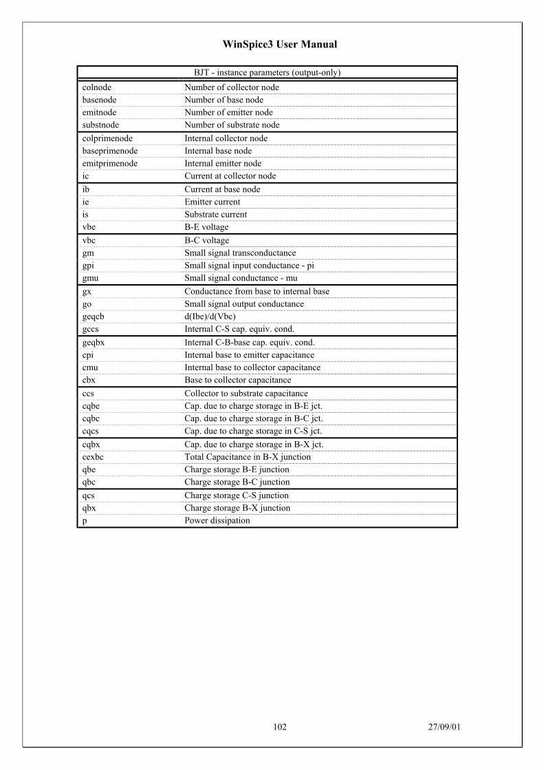
WinSpice3 User Manual
102 27/09/01
BJT - instance parameters (output-only)
colnode Number of collector nodebasenode Number of base nodeemitnode Number of emitter nodesubstnode Number of substrate node
colprimenode Internal collector nodebaseprimenode Internal base nodeemitprimenode Internal emitter nodeic Current at collector node
ib Current at base nodeie Emitter currentis Substrate currentvbe B-E voltage
vbc B-C voltagegm Small signal transconductancegpi Small signal input conductance - pigmu Small signal conductance - mu
gx Conductance from base to internal basego Small signal output conductancegeqcb d(Ibe)/d(Vbc)gccs Internal C-S cap. equiv. cond.
geqbx Internal C-B-base cap. equiv. cond.cpi Internal base to emitter capacitancecmu Internal base to collector capacitancecbx Base to collector capacitance
ccs Collector to substrate capacitancecqbe Cap. due to charge storage in B-E jct.cqbc Cap. due to charge storage in B-C jct.cqcs Cap. due to charge storage in C-S jct.
cqbx Cap. due to charge storage in B-X jct.cexbc Total Capacitance in B-X junctionqbe Charge storage B-E junctionqbc Charge storage B-C junction
qcs Charge storage C-S junctionqbx Charge storage B-X junctionp Power dissipation
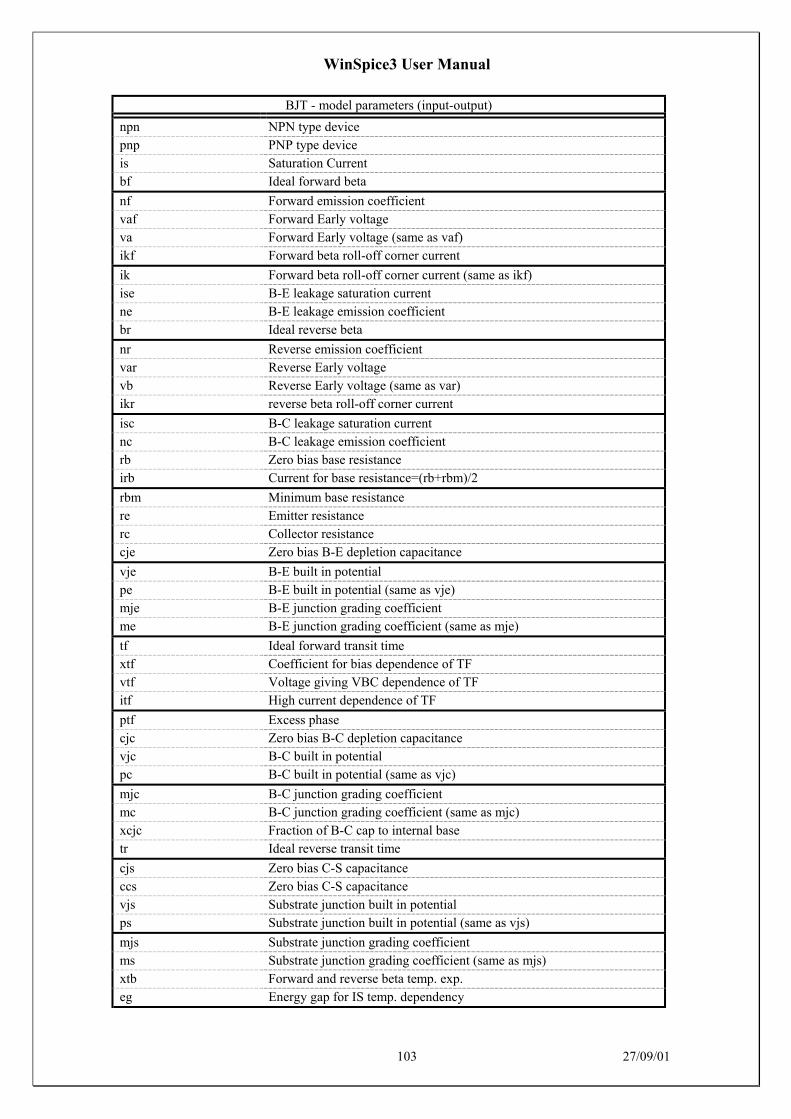
WinSpice3 User Manual
103 27/09/01
BJT - model parameters (input-output)
npn NPN type devicepnp PNP type deviceis Saturation Currentbf Ideal forward beta
nf Forward emission coefficientvaf Forward Early voltageva Forward Early voltage (same as vaf)ikf Forward beta roll-off corner current
ik Forward beta roll-off corner current (same as ikf)ise B-E leakage saturation currentne B-E leakage emission coefficientbr Ideal reverse beta
nr Reverse emission coefficientvar Reverse Early voltagevb Reverse Early voltage (same as var)ikr reverse beta roll-off corner current
isc B-C leakage saturation currentnc B-C leakage emission coefficientrb Zero bias base resistanceirb Current for base resistance=(rb+rbm)/2
rbm Minimum base resistancere Emitter resistancerc Collector resistancecje Zero bias B-E depletion capacitance
vje B-E built in potentialpe B-E built in potential (same as vje)mje B-E junction grading coefficientme B-E junction grading coefficient (same as mje)
tf Ideal forward transit timextf Coefficient for bias dependence of TFvtf Voltage giving VBC dependence of TFitf High current dependence of TF
ptf Excess phasecjc Zero bias B-C depletion capacitancevjc B-C built in potentialpc B-C built in potential (same as vjc)
mjc B-C junction grading coefficientmc B-C junction grading coefficient (same as mjc)xcjc Fraction of B-C cap to internal basetr Ideal reverse transit time
cjs Zero bias C-S capacitanceccs Zero bias C-S capacitancevjs Substrate junction built in potentialps Substrate junction built in potential (same as vjs)
mjs Substrate junction grading coefficientms Substrate junction grading coefficient (same as mjs)xtb Forward and reverse beta temp. exp.eg Energy gap for IS temp. dependency
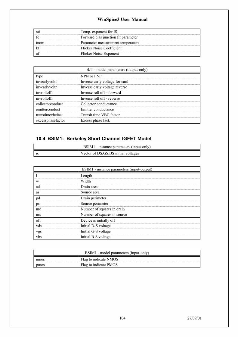
WinSpice3 User Manual
104 27/09/01
xti Temp. exponent for ISfc Forward bias junction fit parametertnom Parameter measurement temperaturekf Flicker Noise Coefficientaf Flicker Noise Exponent
BJT - model parameters (output-only)
type NPN or PNPinvearlyvoltf Inverse early voltage:forwardinvearlyvoltr Inverse early voltage:reverseinvrollofff Inverse roll off - forward
invrolloffr Inverse roll off - reversecollectorconduct Collector conductanceemitterconduct Emitter conductancetranstimevbcfact Transit time VBC factorexcessphasefactor Excess phase fact.
10.4 BSIM1: Berkeley Short Channel IGFET Model
BSIM1 - instance parameters (input-only)
ic Vector of DS,GS,BS initial voltages
BSIM1 - instance parameters (input-output)
l Lengthw Widthad Drain areaas Source area
pd Drain perimeterps Source perimeternrd Number of squares in drainnrs Number of squares in source
off Device is initially offvds Initial D-S voltagevgs Initial G-S voltagevbs Initial B-S voltage
BSIM1 - model parameters (input-only)
nmos Flag to indicate NMOSpmos Flag to indicate PMOS

WinSpice3 User Manual
105 27/09/01
BSIM1 - model parameters (input-output)
vfb Flat band voltagelvfb Length dependence of vfbwvfb Width dependence of vfbphi Strong inversion surface potential
lphi Length dependence of phiwphi Width dependence of phik1 Bulk effect coefficient 1lk1 Length dependence of k1
wk1 Width dependence of k1k2 Bulk effect coefficient 2lk2 Length dependence of k2wk2 Width dependence of k2
eta VDS dependence of threshold voltageleta Length dependence of etaweta Width dependence of etax2e VBS dependence of eta
lx2e Length dependence of x2ewx2e Width dependence of x2ex3e VDS dependence of etalx3e Length dependence of x3e
wx3e Width dependence of x3edl Channel length reduction in umdw Channel width reduction in ummuz Zero field mobility at VDS=0 VGS=VTH
x2mz VBS dependence of muzlx2mz Length dependence of x2mzwx2mz Width dependence of x2mzmus Mobility at VDS=VDD VGS=VTH, channel length modulation
lmus Length dependence of muswmus Width dependence of musx2ms VBS dependence of muslx2ms Length dependence of x2ms
wx2ms Width dependence of x2msx3ms VDS dependence of muslx3ms Length dependence of x3mswx3ms Width dependence of x3ms
u0 VGS dependence of mobilitylu0 Length dependence of u0wu0 Width dependence of u0x2u0 VBS dependence of u0
lx2u0 Length dependence of x2u0wx2u0 Width dependence of x2u0u1 VDS dependence of mobility, velocity saturationlu1 Length dependence of u1
wu1 Width dependence of u1x2u1 VBS dependence of u1lx2u1 Length dependence of x2u1wx2u1 Width dependence of x2u1

WinSpice3 User Manual
106 27/09/01
x3u1 VDS dependence of u1lx3u1 Length dependence of x3u1wx3u1 Width dependence of x3u1n0 Sub threshold slope
ln0 Length dependence of n0wn0 Width dependence of n0nb VBS dependence of sub threshold slopelnb Length dependence of nb
wnb Width dependence of nbnd VDS dependence of sub threshold slopelnd Length dependence of ndwnd Width dependence of nd
tox Gate oxide thickness in umtemp Temperature in degree Celsiusvdd Supply voltage to specify muscgso Gate source overlap capacitance per unit channel width(m)
cgdo Gate drain overlap capacitance per unit channel width(m)cgbo Gate bulk overlap capacitance per unit channel length(m)xpart Flag for channel charge partitioningrsh Source drain diffusion sheet resistance in ohm per square
js Source drain junction saturation current per unit areapb Source drain junction built in potentialmj Source drain bottom junction capacitance grading coefficientpbsw Source drain side junction capacitance built in potential
mjsw Source drain side junction capacitance grading coefficientcj Source drain bottom junction capacitance per unit areacjsw Source drain side junction capacitance per unit areawdf Default width of source drain diffusion in umdell Length reduction of source drain diffusion
10.5 BSIM2: Berkeley Short Channel IGFET Model
BSIM2 - instance parameters (input-only)
ic Vector of DS,GS,BS initial voltages

WinSpice3 User Manual
107 27/09/01
BSIM2 - instance parameters (input-output)
l Lengthw Widthad Drain areaas Source area
pd Drain perimeterps Source perimeternrd Number of squares in drainnrs Number of squares in source
off Device is initially offvds Initial D-S voltagevgs Initial G-S voltagevbs Initial B-S voltage
BSIM2 - model parameters (input-only)
nmos Flag to indicate NMOSpmos Flag to indicate PMOS

WinSpice3 User Manual
108 27/09/01
BSIM2 - model parameters (input-output)
vfb Flat band voltagelvfb Length dependence of vfbwvfb Width dependence of vfbphi Strong inversion surface potential
lphi Length dependence of phiwphi Width dependence of phik1 Bulk effect coefficient 1lk1 Length dependence of k1
wk1 Width dependence of k1k2 Bulk effect coefficient 2lk2 Length dependence of k2wk2 Width dependence of k2
eta0 VDS dependence of threshold voltage at VDD=0leta0 Length dependence of eta0weta0 Width dependence of eta0etab VBS dependence of eta
letab Length dependence of etabwetab Width dependence of etabdl Channel length reduction in umdw Channel width reduction in um
mu0 Low-field mobility, at VDS=0 VGS=VTHmu0b VBS dependence of low-field mobilitylmu0b Length dependence of mu0bwmu0b Width dependence of mu0b
mus0 Mobility at VDS=VDD VGS=VTHlmus0 Length dependence of mus0wmus0 Width dependence of musmusb VBS dependence of mus
lmusb Length dependence of musbwmusb Width dependence of musbmu20 VDS dependence of mu in tanh termlmu20 Length dependence of mu20
wmu20 Width dependence of mu20mu2b VBS dependence of mu2lmu2b Length dependence of mu2bwmu2b Width dependence of mu2b
mu2g VGS dependence of mu2lmu2g Length dependence of mu2gwmu2g Width dependence of mu2gmu30 VDS dependence of mu in linear term
lmu30 Length dependence of mu30wmu30 Width dependence of mu30mu3b VBS dependence of mu3lmu3b Length dependence of mu3b
wmu3b Width dependence of mu3bmu3g VGS dependence of mu3lmu3g Length dependence of mu3gwmu3g Width dependence of mu3g

WinSpice3 User Manual
109 27/09/01
mu40 VDS dependence of mu in linear termlmu40 Length dependence of mu40wmu40 Width dependence of mu40mu4b VBS dependence of mu4
lmu4b Length dependence of mu4bwmu4b Width dependence of mu4bmu4g VGS dependence of mu4lmu4g Length dependence of mu4g
wmu4g Width dependence of mu4gua0 Linear VGS dependence of mobilitylua0 Length dependence of ua0wua0 Width dependence of ua0
uab VBS dependence of ualuab Length dependence of uabwuab Width dependence of uabub0 Quadratic VGS dependence of mobility
lub0 Length dependence of ub0wub0 Width dependence of ub0ubb VBS dependence of ublubb Length dependence of ubb
wubb Width dependence of ubbu10 VDS dependence of mobilitylu10 Length dependence of u10wu10 Width dependence of u10
u1b VBS dependence of u1lu1b Length dependence of u1bwu1b Width dependence of u1bu1d VDS dependence of u1
lu1d Length dependence of u1dwu1d Width dependence of u1dn0 Sub threshold slope at VDS=0 VBS=0ln0 Length dependence of n0
wn0 Width dependence of n0nb VBS dependence of nlnb Length dependence of nbwnb Width dependence of nb
nd VDS dependence of nlnd Length dependence of ndwnd Width dependence of ndvof0 Threshold voltage offset AT VDS=0 VBS=0
lvof0 Length dependence of vof0wvof0 Width dependence of vof0vofb VBS dependence of voflvofb Length dependence of vofb
wvofb Width dependence of vofbvofd VDS dependence of voflvofd Length dependence of vofdwvofd Width dependence of vofd
ai0 Pre-factor of hot-electron effect

WinSpice3 User Manual
110 27/09/01
lai0 Length dependence of ai0wai0 Width dependence of ai0aib VBS dependence of ai
laib Length dependence of aibwaib Width dependence of aibbi0 Exponential factor of hot-electron effectlbi0 Length dependence of bi0
wbi0 Width dependence of bi0bib VBS dependence of bilbib Length dependence of bibwbib Width dependence of bib
vghigh Upper bound of the cubic spline functionlvghigh Length dependence of vghighwvghigh Width dependence of vghighvglow Lower bound of the cubic spline function
lvglow Length dependence of vglowwvglow Width dependence of vglowtox Gate oxide thickness in umtemp Temperature in degree Celsius
vdd Maximum Vdsvgg Maximum Vgsvbb Maximum Vbscgso Gate source overlap capacitance per unit channel width(m)
cgdo Gate drain overlap capacitance per unit channel width(m)cgbo Gate bulk overlap capacitance per unit channel length(m)xpart Flag for channel charge partitioningrsh Source drain diffusion sheet resistance in ohm per square
js Source drain junction saturation current per unit areapb Source drain junction built in potentialmj Source drain bottom junction capacitance grading coefficientpbsw Source drain side junction capacitance built in potential
mjsw Source drain side junction capacitance grading coefficientcj Source drain bottom junction capacitance per unit areacjsw Source drain side junction capacitance per unit areawdf Default width of source drain diffusion in umdell Length reduction of source drain diffusion
10.6 Capacitor: Fixed capacitor
Capacitor - instance parameters (input-output)
capacitance Device capacitanceic Initial capacitor voltagew Device widthl Device length

WinSpice3 User Manual
111 27/09/01
Capacitor - instance parameters (output-only)
i Device currentp Instantaneous device power
Capacitor - model parameters (input-only)
c Capacitor model
Capacitor - model parameters (input-output)
cj Bottom Capacitance per areacjsw Sidewall capacitance per meterdefw Default widthtc1 First order temp. coefficient
tc2 Second order temp. coefficientvc1 First order voltage coefficientvc2 Second order voltage coefficientnarrow Width correction factor
10.7 CCCS: Current controlled current source
CCCS - instance parameters (input-output)
gain Gain of sourcecontrol Name of controlling source
CCCS - instance parameters (output-only)
neg_node Negative node of sourcepos_node Positive node of sourcei CCCS output currentv CCCS voltage at outputp CCCS power
10.8 CCVS: Linear current controlled current source
CCVS - instance parameters (input-output)
gain Transresistance (gain)control Controlling voltage source
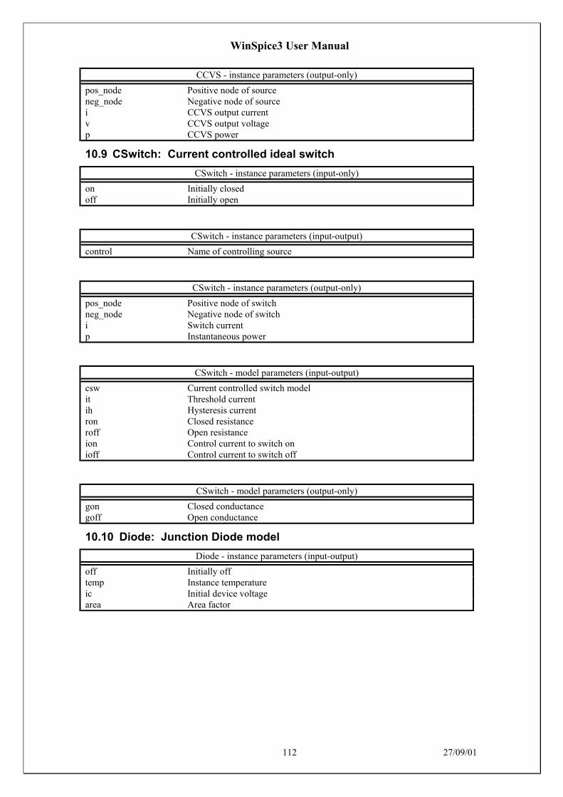
WinSpice3 User Manual
112 27/09/01
CCVS - instance parameters (output-only)
pos_node Positive node of sourceneg_node Negative node of sourcei CCVS output currentv CCVS output voltagep CCVS power
10.9 CSwitch: Current controlled ideal switch
CSwitch - instance parameters (input-only)
on Initially closedoff Initially open
CSwitch - instance parameters (input-output)
control Name of controlling source
CSwitch - instance parameters (output-only)
pos_node Positive node of switchneg_node Negative node of switchi Switch currentp Instantaneous power
CSwitch - model parameters (input-output)
csw Current controlled switch modelit Threshold currentih Hysteresis currentron Closed resistanceroff Open resistanceion Control current to switch onioff Control current to switch off
CSwitch - model parameters (output-only)
gon Closed conductancegoff Open conductance
10.10 Diode: Junction Diode model
Diode - instance parameters (input-output)
off Initially offtemp Instance temperatureic Initial device voltagearea Area factor

WinSpice3 User Manual
113 27/09/01
Diode – instance parameters (output-only)
vd Diode voltageid Diode currentc Diode currentgd Diode conductancecd Diode capacitancecharge Diode capacitor chargecapcur Diode capacitor currentp Diode power
Diode - model parameters (input-only)
d Diode model
Diode - model parameters (input-output)
is Saturation currenttnom Parameter measurement temperaturers Ohmic resistancen Emission Coefficienttt Transit Timecjo Junction capacitancecj0 (null)vj Junction potentialm Grading coefficienteg Activation energyxti Saturation current temperature exp.kf flicker noise coefficientaf flicker noise exponentfc Forward bias junction fit parameterbv Reverse breakdown voltageibv Current at reverse breakdown voltage
Diode - model parameters (output-only)
cond Ohmic conductance
10.11 Inductor: Inductors
Inductor - instance parameters (input-output)
inductance Inductance of inductoric Initial current through inductor
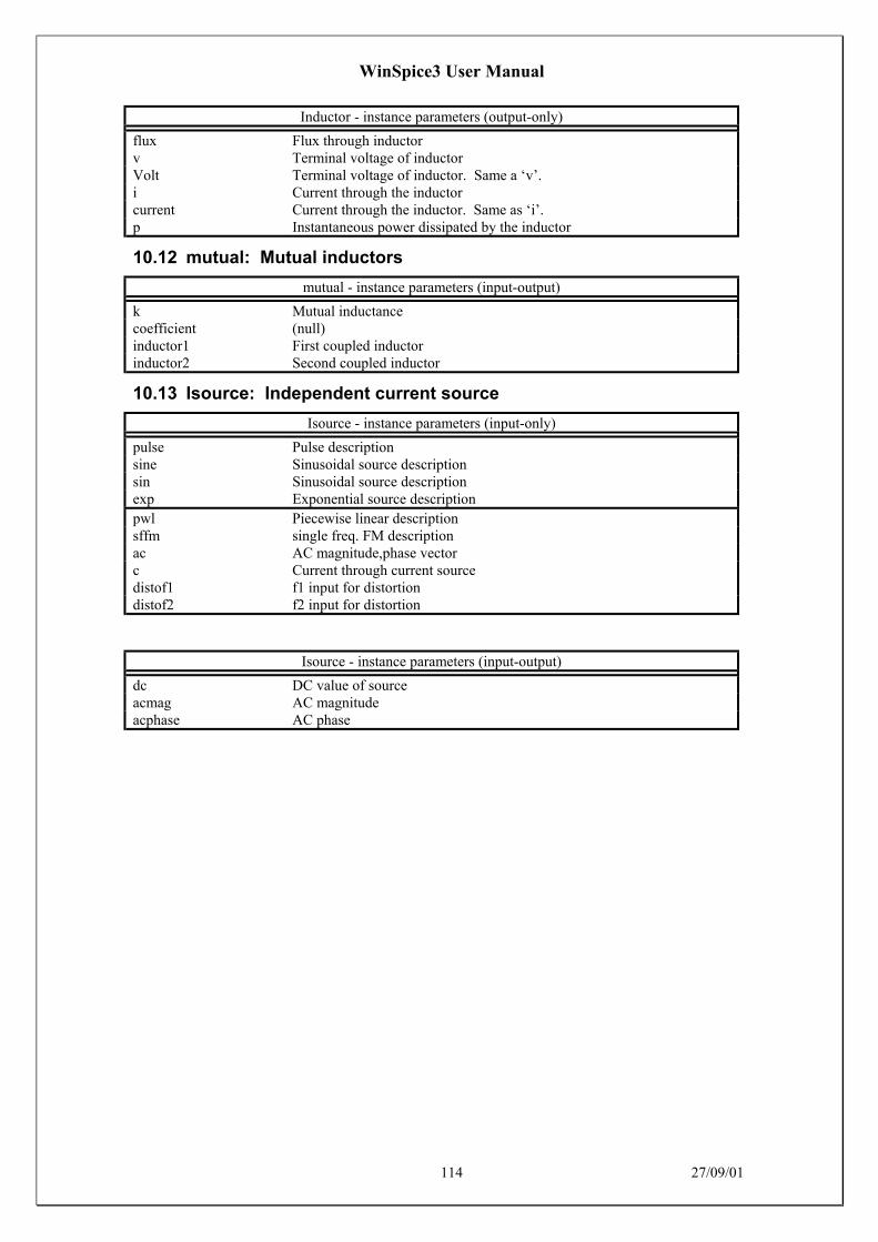
WinSpice3 User Manual
114 27/09/01
Inductor - instance parameters (output-only)
flux Flux through inductorv Terminal voltage of inductorVolt Terminal voltage of inductor. Same a ‘v’.i Current through the inductorcurrent Current through the inductor. Same as ‘i’.p Instantaneous power dissipated by the inductor
10.12 mutual: Mutual inductors
mutual - instance parameters (input-output)
k Mutual inductancecoefficient (null)inductor1 First coupled inductorinductor2 Second coupled inductor
10.13 Isource: Independent current source
Isource - instance parameters (input-only)
pulse Pulse descriptionsine Sinusoidal source descriptionsin Sinusoidal source descriptionexp Exponential source descriptionpwl Piecewise linear descriptionsffm single freq. FM descriptionac AC magnitude,phase vectorc Current through current sourcedistof1 f1 input for distortiondistof2 f2 input for distortion
Isource - instance parameters (input-output)
dc DC value of sourceacmag AC magnitudeacphase AC phase
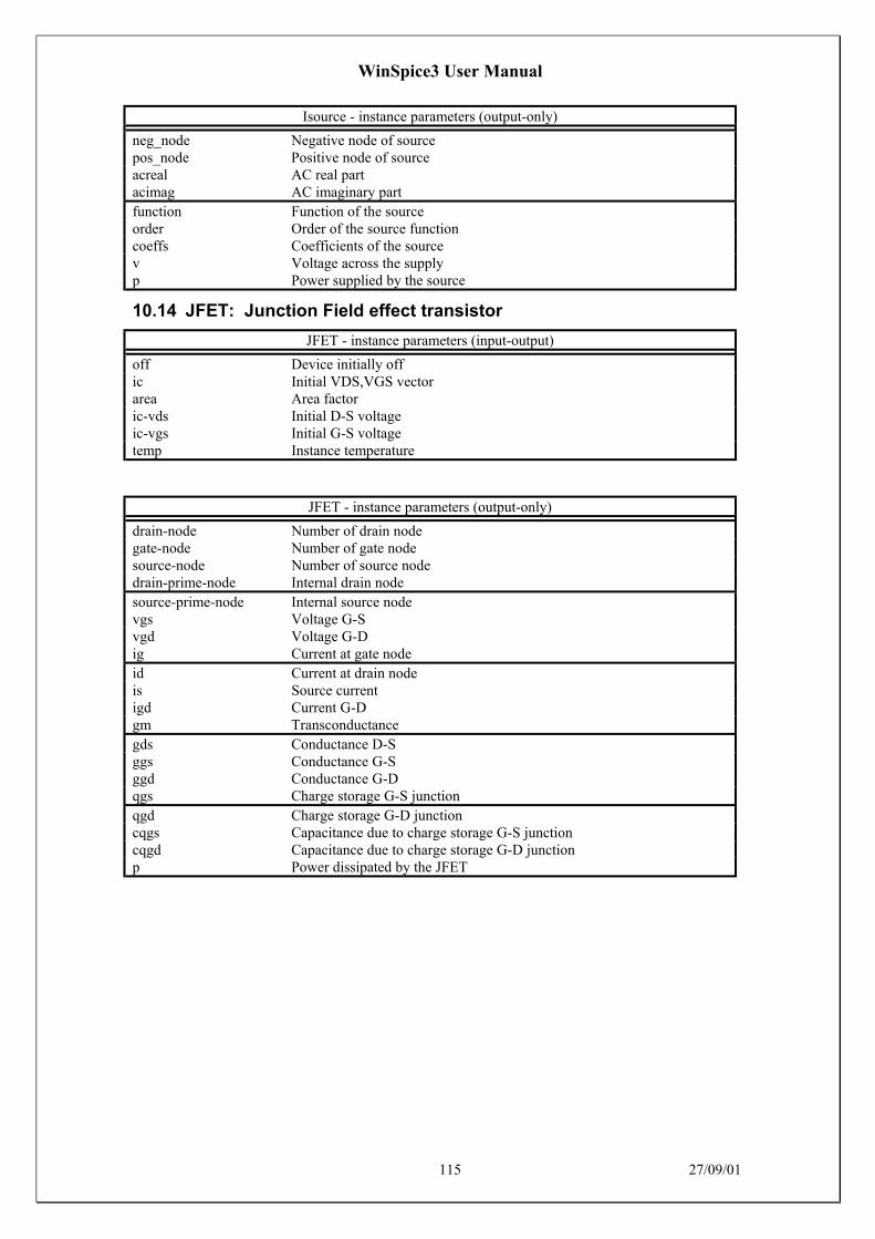
WinSpice3 User Manual
115 27/09/01
Isource - instance parameters (output-only)
neg_node Negative node of sourcepos_node Positive node of sourceacreal AC real partacimag AC imaginary partfunction Function of the sourceorder Order of the source functioncoeffs Coefficients of the sourcev Voltage across the supplyp Power supplied by the source
10.14 JFET: Junction Field effect transistor
JFET - instance parameters (input-output)
off Device initially offic Initial VDS,VGS vectorarea Area factoric-vds Initial D-S voltageic-vgs Initial G-S voltagetemp Instance temperature
JFET - instance parameters (output-only)
drain-node Number of drain nodegate-node Number of gate nodesource-node Number of source nodedrain-prime-node Internal drain nodesource-prime-node Internal source nodevgs Voltage G-Svgd Voltage G-Dig Current at gate nodeid Current at drain nodeis Source currentigd Current G-Dgm Transconductancegds Conductance D-Sggs Conductance G-Sggd Conductance G-Dqgs Charge storage G-S junctionqgd Charge storage G-D junctioncqgs Capacitance due to charge storage G-S junctioncqgd Capacitance due to charge storage G-D junctionp Power dissipated by the JFET

WinSpice3 User Manual
116 27/09/01
JFET - model parameters (input-output)
njf N type JFET modelpjf P type JFET modelvt0 Threshold voltagevto Threshold voltagebeta Transconductance parameterlambda Channel length modulation param.rd Drain ohmic resistancers Source ohmic resistancecgs G-S junction capacitancecgd G-D junction cappb Gate junction potentialis Gate junction saturation currentfc Forward bias junction fit parm.b Doping tail parametertnom Parameter measurement temperaturekf Flicker Noise Coefficientaf Flicker Noise Exponent
JFET - model parameters (output-only)
type N-type or P-type JFET modelgd Drain conductancegs Source conductance
10.15 LTRA: Lossy transmission line
LTRA - instance parameters (input-only)
ic Initial condition vector:v1,i1,v2,i2
LTRA - instance parameters (input-output)
v1 Initial voltage at end 1v2 Initial voltage at end 2i1 Initial current at end 1i2 Initial current at end 2
LTRA - instance parameters (output-only)
pos_node1 Positive node of end 1 of t-lineneg_node1 Negative node of end 1 of t.linepos_node2 Positive node of end 2 of t-lineneg_node2 Negative node of end 2 of t-line

WinSpice3 User Manual
117 27/09/01
LTRA - model parameters (input-output)
ltra LTRA modelr Resistance per metrel Inductance per metreg (null)c Capacitance per metrelen Length of linenocontrol No timestep controlsteplimit Always limit timestep to 0.8*(delay of line)nosteplimit Don't always limit timestep to 0.8*(delay of line)lininterp Use linear interpolationquadinterp Use quadratic interpolationmixedinterp Use linear interpolation if quadratic results look unacceptabletruncnr Use N-R iterations for step calculation in LTRAtrunctruncdontcut Don't limit timestep to keep impulse response calculation errors lowcompactrel Special reltol for straight line checkingcompactabs Special abstol for straight line checking
LTRA - model parameters (output-only)
rel Rel. rate of change of deriv. for bkptabs Abs. rate of change of deriv. for bkpt
10.16 MES: GaAs MESFET model
MES - instance parameters (input-output)
area Area factoricvds Initial D-S voltageicvgs Initial G-S voltage
MES - instance parameters (output-only)
off Device initially offdnode Number of drain nodegnode Number of gate nodesnode Number of source nodedprimenode Number of internal drain nodesprimenode Number of internal source nodevgs Gate-Source voltagevgd Gate-Drain voltagecg Gate capacitancecd Drain capacitancecgd Gate-Drain capacitancegm Transconductancegds Drain-Source conductanceggs Gate-Source conductanceggd Gate-Drain conductancecqgs Capacitance due to gate-source charge storagecqgd Capacitance due to gate-drain charge storageqgs Gate-Source charge storageqgd Gate-Drain charge storageis Source currentp Power dissipated by the mesfet

WinSpice3 User Manual
118 27/09/01
MES - model parameters (input-only)
nmf N type MESfet modelpmf P type MESfet model
MES - model parameters (input-output)
vt0 Pinch-off voltagevto Pinch-off voltagealpha Saturation voltage parameterbeta Transconductance parameterlambda Channel length modulation parm.b Doping tail extending parameterrd Drain ohmic resistancers Source ohmic resistancecgs G-S junction capacitancecgd G-D junction capacitancepb Gate junction potentialis Junction saturation currentfc Forward bias junction fit parm.kf Flicker noise coefficientaf Flicker noise exponent
MES - model parameters (output-only)
type N-type or P-type MESfet modelgd Drain conductancegs Source conductancedepl_cap Depletion capacitancevcrit Critical voltage
10.17 Mos1: Level 1 MOSFET model with Meyer capacitance model
Mos1 - instance parameters (input-only)
off Device initially offic Vector of D-S, G-S, B-S voltages
Mos1 - instance parameters (input-output)
l Lengthw Widthad Drain areaas Source areapd Drain perimeterps Source perimeternrd Drain squaresnrs Source squaresicvds Initial D-S voltageicvgs Initial G-S voltageicvbs Initial B-S voltagetemp Instance temperature

WinSpice3 User Manual
119 27/09/01
Mos1 - instance parameters (output-only)
id Drain currentis Source currentig Gate currentib Bulk currentibd B-D junction currentibs B-S junction currentvgs Gate-Source voltagevds Drain-Source voltagevbs Bulk-Source voltagevbd Bulk-Drain voltagednode Number of the drain nodegnode Number of the gate nodesnode Number of the source nodebnode Number of the nodednodeprime Number of int. drain nodesnodeprime Number of int. source nodevon Turn-on voltagevdsat Saturation drain voltagesourcevcrit Critical source voltagedrainvcrit Critical drain voltagers Source resistancesourceconductance Conductance of sourcerd Drain conductancedrainconductance Conductance of draingm Transconductancegds Drain-Source conductancegmb Bulk-Source transconductancegmbs Bulk-Source transconductancegbd Bulk-Drain conductancegbs Bulk-Source conductancecbd Bulk-Drain capacitancecbs Bulk-Source capacitancecgs Gate-Source capacitancecgd Gate-Drain capacitancecgb Gate-Bulk capacitancecqgs Capacitance due to gate-source charge storagecqgd Capacitance due to gate-drain charge storagecqgb Capacitance due to gate-bulk charge storagecqbd Capacitance due to bulk-drain charge storagecqbs Capacitance due to bulk-source charge storagecbd0 Zero-Bias B-D junction capacitancecbdsw0cbs0 Zero-Bias B-S junction capacitancecbssw0qgs Gate-Source charge storageqgd Gate-Drain charge storageqgb Gate-Bulk charge storageqbd Bulk-Drain charge storageqbs Bulk-Source charge storagep Instantaneous power

WinSpice3 User Manual
120 27/09/01
Mos1 - model parameters (input-only)
nmos N type MOSFET modelpmos P type MOSFET model
Mos1 - model parameters (input-output)
vto Threshold voltagevt0 Threshold voltagekp Transconductance parametergamma Bulk threshold parameterphi Surface potentiallambda Channel length modulationrd Drain ohmic resistancers Source ohmic resistancecbd B-D junction capacitancecbs B-S junction capacitanceis Bulk junction sat. currentpb Bulk junction potentialcgso Gate-source overlap cap.cgdo Gate-drain overlap cap.cgbo Gate-bulk overlap cap.rsh Sheet resistancecj Bottom junction cap per areamj Bottom grading coefficientcjsw Side junction cap per areamjsw Side grading coefficientjs Bulk jct. sat. current densitytox Oxide thicknessld Lateral diffusionu0 Surface mobilityuo Surface mobilityfc Forward bias jct. fit parm.nsub Substrate dopingtpg Gate typenss Surface state densitytnom Parameter measurement temperaturekf Flicker noise coefficientaf Flicker noise exponent
Mos1 - model parameters (output-only)
type N-channel or P-channel MOS
10.18 Mos2: Level 2 MOSFET model with Meyer capacitance model
Mos2 - instance parameters (input-only)
off Device initially offic Vector of D-S, G-S, B-S voltages

WinSpice3 User Manual
121 27/09/01
Mos2 - instance parameters (input-output)
l Lengthw Widthad Drain areaas Source areapd Drain perimeterps Source perimeternrd Drain squaresnrs Source squaresicvds Initial D-S voltageicvgs Initial G-S voltageicvbs Initial B-S voltagetemp Instance operating temperature
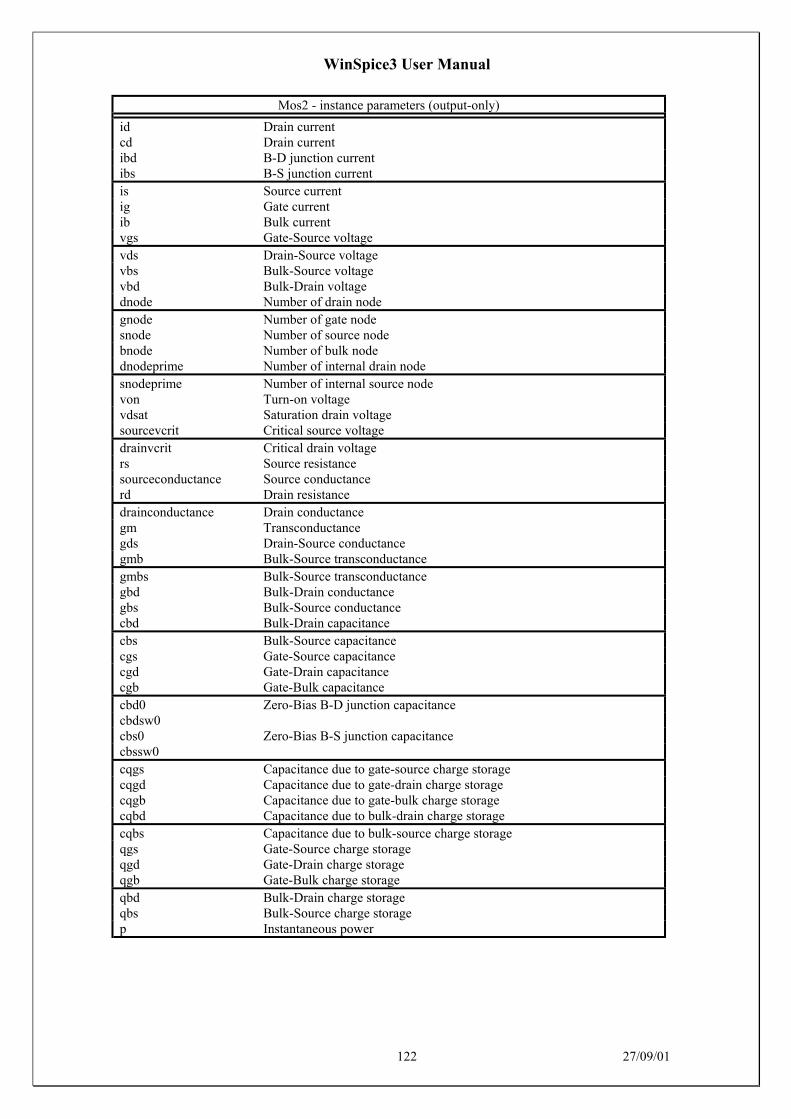
WinSpice3 User Manual
122 27/09/01
Mos2 - instance parameters (output-only)
id Drain currentcd Drain currentibd B-D junction currentibs B-S junction currentis Source currentig Gate currentib Bulk currentvgs Gate-Source voltagevds Drain-Source voltagevbs Bulk-Source voltagevbd Bulk-Drain voltagednode Number of drain nodegnode Number of gate nodesnode Number of source nodebnode Number of bulk nodednodeprime Number of internal drain nodesnodeprime Number of internal source nodevon Turn-on voltagevdsat Saturation drain voltagesourcevcrit Critical source voltagedrainvcrit Critical drain voltagers Source resistancesourceconductance Source conductancerd Drain resistancedrainconductance Drain conductancegm Transconductancegds Drain-Source conductancegmb Bulk-Source transconductancegmbs Bulk-Source transconductancegbd Bulk-Drain conductancegbs Bulk-Source conductancecbd Bulk-Drain capacitancecbs Bulk-Source capacitancecgs Gate-Source capacitancecgd Gate-Drain capacitancecgb Gate-Bulk capacitancecbd0 Zero-Bias B-D junction capacitancecbdsw0cbs0 Zero-Bias B-S junction capacitancecbssw0cqgs Capacitance due to gate-source charge storagecqgd Capacitance due to gate-drain charge storagecqgb Capacitance due to gate-bulk charge storagecqbd Capacitance due to bulk-drain charge storagecqbs Capacitance due to bulk-source charge storageqgs Gate-Source charge storageqgd Gate-Drain charge storageqgb Gate-Bulk charge storageqbd Bulk-Drain charge storageqbs Bulk-Source charge storagep Instantaneous power

WinSpice3 User Manual
123 27/09/01
Mos2 - model parameters (input-only)
nmos N type MOSFET modelpmos P type MOSFET model
Mos2 - model parameters (input-output)
vto Threshold voltagevt0 Threshold voltagekp Transconductance parametergamma Bulk threshold parameterphi Surface potentiallambda Channel length modulationrd Drain ohmic resistancers Source ohmic resistancecbd B-D junction capacitancecbs B-S junction capacitanceis Bulk junction sat. currentpb Bulk junction potentialcgso Gate-source overlap cap.cgdo Gate-drain overlap cap.cgbo Gate-bulk overlap cap.rsh Sheet resistancecj Bottom junction cap per areamj Bottom grading coefficientcjsw Side junction cap per areamjsw Side grading coefficientjs Bulk jct. sat. current densitytox Oxide thicknessld Lateral diffusionu0 Surface mobilityuo Surface mobilityfc Forward bias jct. fit parm.nsub Substrate dopingtpg Gate typenss Surface state densitydelta Width effect on thresholduexp Crit. field exp for mob. deg.ucrit Crit. field for mob. degradationvmax Maximum carrier drift velocityxj Junction depthneff Total channel charge coeff.nfs Fast surface state densitytnom Parameter measurement temperaturekf Flicker noise coefficientaf Flicker noise exponent
Mos2 - model parameters (output-only)
type N-channel or P-channel MOS
10.19 Mos3: Level 3 MOSFET model with Meyer capacitance model
Mos3 - instance parameters (input-only)
off Device initially off

WinSpice3 User Manual
124 27/09/01
Mos3 - instance parameters (input-output)
l Lengthw Widthad Drain areaas Source areapd Drain perimeterps Source perimeternrd Drain squaresnrs Source squaresicvds Initial D-S voltageicvgs Initial G-S voltageicvbs Initial B-S voltageic Vector of D-S, G-S, B-S voltagestemp Instance operating temperature

WinSpice3 User Manual
125 27/09/01
Mos3 - instance parameters (output-only)
id Drain currentcd Drain currentibd B-D junction currentibs B-S junction currentis Source currentig Gate currentib Bulk currentvgs Gate-Source voltagevds Drain-Source voltagevbs Bulk-Source voltagevbd Bulk-Drain voltagednode Number of drain nodegnode Number of gate nodesnode Number of source nodebnode Number of bulk nodednodeprime Number of internal drain nodesnodeprime Number of internal source nodevon Turn-on voltagevdsat Saturation drain voltagesourcevcrit Critical source voltagedrainvcrit Critical drain voltagers Source resistancesourceconductance Source conductancerd Drain resistancedrainconductance Drain conductancegm Transconductancegds Drain-Source conductancegmb Bulk-Source transconductancegmbs Bulk-Source transconductancegbd Bulk-Drain conductancegbs Bulk-Source conductancecbd Bulk-Drain capacitancecbs Bulk-Source capacitancecgs Gate-Source capacitancecgd Gate-Drain capacitancecgb Gate-Bulk capacitancecqgs Capacitance due to gate-source charge storagecqgd Capacitance due to gate-drain charge storagecqgb Capacitance due to gate-bulk charge storagecqbd Capacitance due to bulk-drain charge storagecqbs Capacitance due to bulk-source charge storagecbd0 Zero-Bias B-D junction capacitancecbdsw0 Zero-Bias B-D sidewall capacitancecbs0 Zero-Bias B-S junction capacitancecbssw0 Zero-Bias B-S sidewall capacitanceqbs Bulk-Source charge storageqgs Gate-Source charge storageqgd Gate-Drain charge storageqgb Gate-Bulk charge storageqbd Bulk-Drain charge storagep Instantaneous power

WinSpice3 User Manual
126 27/09/01
Mos3 - model parameters (input-only)
nmos N type MOSFET modelpmos P type MOSFET model
Mos3 - model parameters (input-output)
vto Threshold voltagevt0 Threshold voltagekp Transconductance parametergamma Bulk threshold parameterphi Surface potentialrd Drain ohmic resistancers Source ohmic resistancecbd B-D junction capacitancecbs B-S junction capacitanceis Bulk junction sat. currentpb Bulk junction potentialcgso Gate-source overlap cap.cgdo Gate-drain overlap cap.cgbo Gate-bulk overlap cap.rsh Sheet resistancecj Bottom junction cap per areamj Bottom grading coefficientcjsw Side junction cap per areamjsw Side grading coefficientjs Bulk jct. sat. current densitytox Oxide thicknessld Lateral diffusionu0 Surface mobilityuo Surface mobilityfc Forward bias jct. fit parm.nsub Substrate dopingtpg Gate typenss Surface state densityvmax Maximum carrier drift velocityxj Junction depthnfs Fast surface state densityxd Depletion layer widthalpha Alphaeta Vds dependence of threshold voltagedelta Width effect on thresholdinput_delta (null)theta Vgs dependence on mobilitykappa Kappatnom Parameter measurement temperaturekf Flicker noise coefficientaf Flicker noise exponent

WinSpice3 User Manual
127 27/09/01
Mos3 - model parameters (output-only)
type N-channel or P-channel MOS
10.20 Mos6: Level 6 MOSFET model with Meyer capacitance model
Mos6 - instance parameters (input-only)
off Device initially offic Vector of D-S, G-S, B-S voltages
Mos6 - instance parameters (input-output)
l Lengthw Widthad Drain areaas Source areapd Drain perimeterps Source perimeternrd Drain squaresnrs Source squaresicvds Initial D-S voltageicvgs Initial G-S voltageicvbs Initial B-S voltagetemp Instance temperature

WinSpice3 User Manual
128 27/09/01
Mos6 - instance parameters (output-only)
id Drain currentcd Drain currentis Source currentig Gate currentib Bulk currentibs B-S junction capacitanceibd B-D junction capacitancevgs Gate-Source voltagevds Drain-Source voltagevbs Bulk-Source voltagevbd Bulk-Drain voltagednode Number of the drain nodegnode Number of the gate nodesnode Number of the source nodebnode Number of the nodednodeprime Number of int. drain nodesnodeprime Number of int. source noders Source resistancesourceconductance Source conductancerd Drain resistancedrainconductance Drain conductancevon Turn-on voltagevdsat Saturation drain voltagesourcevcrit Critical source voltagedrainvcrit Critical drain voltagegmbs Bulk-Source transconductancegm Transconductancegds Drain-Source conductancegbd Bulk-Drain conductancegbs Bulk-Source conductancecgs Gate-Source capacitancecgd Gate-Drain capacitancecgb Gate-Bulk capacitancecbd Bulk-Drain capacitancecbs Bulk-Source capacitancecbd0 Zero-Bias B-D junction capacitancecbdsw0cbs0 Zero-Bias B-S junction capacitancecbssw0cqgs Capacitance due to gate-source charge storagecqgd Capacitance due to gate-drain charge storagecqgb Capacitance due to gate-bulk charge storagecqbd Capacitance due to bulk-drain charge storagecqbs Capacitance due to bulk-source charge storageqgs Gate-Source charge storageqgd Gate-Drain charge storageqgb Gate-Bulk charge storageqbd Bulk-Drain charge storageqbs Bulk-Source charge storagep Instantaneous power

WinSpice3 User Manual
129 27/09/01
Mos6 - model parameters (input-only)
nmos N type MOSFET modelpmos P type MOSFET model
Mos6 - model parameters (input-output)
vto Threshold voltagevt0 Threshold voltagekv Saturation voltage factornv Saturation voltage coeff.kc Saturation current factornc Saturation current coeff.nvth Threshold voltage coeff.ps Sat. current modification par.gamma Bulk threshold parametergamma1 Bulk threshold parameter 1sigma Static feedback effect par.phi Surface potentiallambda Channel length modulation param.lambda0 Channel length modulation param. 0lambda1 Channel length modulation param. 1rd Drain ohmic resistancers Source ohmic resistancecbd B-D junction capacitancecbs B-S junction capacitanceis Bulk junction sat. currentpb Bulk junction potentialcgso Gate-source overlap cap.cgdo Gate-drain overlap cap.cgbo Gate-bulk overlap cap.rsh Sheet resistancecj Bottom junction cap per areamj Bottom grading coefficientcjsw Side junction cap per areamjsw Side grading coefficientjs Bulk jct. sat. current densityld Lateral diffusiontox Oxide thicknessu0 Surface mobilityuo Surface mobilityfc Forward bias jct. fit parm.tpg Gate typensub Substrate dopingnss Surface state densitytnom Parameter measurement temperature

WinSpice3 User Manual
130 27/09/01
Mos6 - model parameters (output-only)
type N-channel or P-channel MOS
10.21 Resistor: Simple resistor
Resistor - instance parameters (input-output)
resistance Resistancetemp Instance operating temperaturel Lengthw Width
Resistor - instance parameters (output-only)
i Currentp Power
Resistor - model parameters (input-only)
r Device is a resistor model
Resistor - model parameters (input-output)
rsh Sheet resistancenarrow Narrowing of resistortc1 First order temp. coefficienttc2 Second order temp. coefficientdefw Default device widthtnom Parameter measurement temperature
10.22 Switch: Ideal voltage controlled switch
Switch - instance parameters (input-only)
on Switch initially closedoff Switch initially open
Switch - instance parameters (input-output)
pos_node Positive node of switchneg_node Negative node of switch
Switch - instance parameters (output-only)
cont_p_node Positive contr. node of switchcont_n_node Positive contr. node of switchi Switch currentp Switch power

WinSpice3 User Manual
131 27/09/01
Switch - model parameters (input-output)
sw Switch modelvt Threshold voltagevh Hysteresis voltageron Resistance when closedroff Resistance when openvon Control voltage to switch onvoff Control voltage to switch off
Switch - model parameters (output-only)
gon Conductance when closedgoff Conductance when open
10.23 Tranline: Lossless transmission line
Tranline - instance parameters (input-only)
ic Initial condition vector:v1,i1,v2,i2
Tranline - instance parameters (input-output)
z0 Characteristic impedancezo Characteristic impedancef Frequencytd Transmission delaynl Normalized length at frequency givenv1 Initial voltage at end 1v2 Initial voltage at end 2i1 Initial current at end 1i2 Initial current at end 2
Tranline - instance parameters (output-only)
rel Rel. rate of change of deriv. for bkptabs Abs. rate of change of deriv. for bkptpos_node1 Positive node of end 1 of t. lineneg_node1 Negative node of end 1 of t. linepos_node2 Positive node of end 2 of t. lineneg_node2 Negative node of end 2 of t. linedelays Delayed values of excitation
10.24 VCCS: Voltage controlled current source
VCCS - instance parameters (input-output)
gain Transconductance of source (gain)

WinSpice3 User Manual
132 27/09/01
VCCS - instance parameters (output-only)
pos_node Positive node of sourceneg_node Negative node of sourcecont_p_node Positive node of contr. sourcecont_n_node Negative node of contr. sourcei Output currentv Voltage across outputp Power
10.25 VCVS: Voltage controlled voltage source
VCVS - instance parameters (input-only)
ic Initial condition of controlling source
VCVS - instance parameters (input-output)
gain Voltage gain
VCVS - instance parameters (output-only)
pos_node Positive node of sourceneg_node Negative node of sourcecont_p_node Positive node of contr. sourcecont_n_node Negative node of contr. sourcei Output currentv Output voltagep Power
10.26 Vsource: Independent voltage source
Vsource - instance parameters (input-only)
pulse Pulse descriptionsine Sinusoidal source descriptionsin Sinusoidal source descriptionexp Exponential source descriptionpwl Piecewise linear descriptionsffm Single freq. FM descriptionac AC magnitude, phase vectordistof1 f1 input for distortiondistof2 f2 input for distortion
Vsource - instance parameters (input-output)
dc D.C. source valueacmag A.C. Magnitudeacphase A.C. Phase

WinSpice3 User Manual
133 27/09/01
Vsource - instance parameters (output-only)
pos_node Positive node of sourceneg_node Negative node of sourcefunction Function of the sourceorder Order of the source functioncoeffs Coefficients for the functionacreal AC real partacimag AC imaginary parti Voltage source currentp Instantaneous power