winslow fr-200 · fr-200 method form relief edge ... #5c spindle taper up to 1” collet #33...
TRANSCRIPT

1
Winslow® FR-200Form Relief Grinder

2
This Form Relief GrinderOutperforms Primary/SecondaryGrinding 6 Ways
1 One Machine Does Multiple
TasksStandard machine accommodates cutting tools with shaft diameters up to 1–1/2”, and requires no special tools, jigs, or xtures to complete sharpening operations. It’s complete in itself.
2 Better Cutting Edge Support
Reduces Tool WearForm relief grinding requires just a single setup and a slightly curved grinding path to dress the cutting edge; consequently, ample metal remains to support the edge and absorb damaging heat... the major cause of tool wear and breakage. The form relief method also improves tools previously sharpened by the primary/secondary relief method because less metal is removed with recurring sharpenings.
3 IncreasedBody Strength
Reduces Tool BreakageStep tools and others that perform two operations can be precision sharpened without undercutting at intersections. The elimination of intersection gashing increases tool body strength and greatly reduces tool breakage.
4 High-Speed Cutting Improves
Productivity And ProtBecause more metal remains behind the cutting edge to absorb heat and shock, the cutting tool can operate at higher cutting speeds. Result: Reduced manufacturing costs and higher quality performance.
5 ProperCutting-Tool
Balance Maintains EdgeTaps, counterbores, and reamers having several “lands” are sharpened with same length, diameter and relief on each cutting edge – so lands load evenly. This eliminates chatter, permits greater feedrates, and lengthens the interval between tool sharpenings.
6 Burr-FreeEdge Prevents
Cutter Failure Because the grinding wheel rotates into the cutting edge, a precision burr-free edge is produced at the intersection of relief and margin. If no margin is desired, a burr-free knife edge is produced with form relief extending from the cutting edge to the heel of the tool. This contributes to cooler operation, prevents galling and/or premature breakdown of the cutting edge.
The machines and products illustrated in this catalog are protected by United States and foreign patents, Illustrations and specications published in this catalog are not binding in detail as Winslow Engineering reserves the right to make and incorporate design changes and improvements without notice, as conditions warrant. Copyright 2001 Winslow Engineering, Inc.
StepSpotface
TrepanningCutter
SpiralFlute Tap
PunchInsert
StepReamer
MillCutter
3
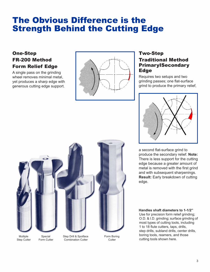
The Obvious Difference is theStrength Behind the Cutting Edge
One-Step FR-200 Method Form Relief Edge A single pass on the grinding wheel removes minimal metal, yet produces a sharp edge with generous cutting edge support.
Two-Step Traditional Method PrimaryISecondary EdgeRequires two setups and two grinding passes; one at-surface grind to produce the primary relief,
a second at-surface grind to produce the secondary relief. Note: There is less support for the cutting edge because a greater amount of metal is removed with the rst grind and with subsequent sharpenings. Result: Early breakdown of cutting edge.
Handles shaft diameters to 1-1/2” Use for precision form relief grinding; O.D. & I.D. grinding; surface grinding of most types of cutting tools, including 1 to 18 ute cutters, taps, drills, step drills, subland drills, center drills, boring tools, reamers, and those cutting tools shown here.
MultipleStep Cutter
SpecialForm Cutter
Step Drill & SpotfaceCombination Cutter
Form BoringCutter

4
Study, Compact Design BringsAll Elements to Your Fingertips
Trav-A-Dial lndicator Veries True GrindOptional indicator measures position movement in .001” increments over the full 26” of table
travel. Mounts on base. Allows inspection of cutting tool lengths prior to removing from workhead.
Handy Wheel Dresser Saves TimeThis ( optional ) accessory dresses the grinding wheel face parallel to the table and at any desired angle. Dresser diamond is adjustable. Column rotates 360°. Unit locks in table T-slots.
Optical Comparator Veries Tool FormOptional accessory has 10° diameter viewing screen and offers 10x & 20x magnication of work zone. Inspection of cutting tool for precise tolerances can be accomplished prior to removal from the workhead.
Machine Table Allows Fast Traverse And Precision PositioningTable has 60” x 14” work surface and slides on a hardened, precision-ground way system. Includes coolant lip and drain, and T-slot for mounting xtures and accessories. Table features rapid traverse and ne feed positioning and offers adjustable stops.
Machine Base Provides Stiff SupportThis heavy-duty weldment features coolant lip with drain and 3-point screw leveling. Designed for optional built-in coolant system.
Wheelhead Cross-Slide Positions In Increments of .0005”Heavy dovetail ways offer smooth precise motion. Stress-relieved steel leadscrew has double-nut adjustment to prevent backlash. Workhead Offers
Simple SetupAction zone is designed for quick operator access. All controls are visible and within easy reach. A single cam and two proportioning slides generate independent axis motions. Up to .100” radial relief and up to .250” axial relief can be generated separately or in any combination.

5
Workhead Motor Offers Variable Speed AdjustmentThe 1/8 hp, DC workhead drive system offers stepless speed adjustment from 0 to 85 rpm with either left or right-hand spindle rotation.
High-Speed, Grindwheel Attachment Increases Machine OutputOptional, self -contained spindle and motor unit provide variable speed from 10,000 to 40,000 rpm. Produces 1.5 hp continuously. Mounts to back side of column. Special controls provided. Refer to photo on page 7.
Wheelhead Holds Two Grinding Wheels To Save Time, Boost ProductivityStandard 1 hp drive system (230/460 ac) permits 3600 rpm power to both grinding wheels. Accommodates up to 7” diameter wheels. As an option, a variable speed drive is available for speeds up to 7200 rpm.
Wheelhead Column Mounts Firmly, Swivels 360°The 10” diameter column base provides rigid support for the traveling wheelhead unit(s) .Rotates 360° to use optional, high-speed wheelhead attachment.
Controls Center Offers Convenient Access
1 Grinding wheel and workhead controls, coolant
switch, comparator switch, worklight switch.
2 Fine-feed handwheel for table travel.
3 Table traverse handwheel.
4 Handwheel for column cross-slide.
Digital Readout For X & Y AxesA (2) axes digital readout unit can be provided to accomplish accurate table and column infeed positioning. The digital readout unit includes the following features: key entry, memory preset, inch/metric conversion, axis indicator, decimal point entry, absolute zero recall/ incremental positioning and self-diagnostics.
Steadyrest Unit AccommodatesLong ToolsSteadyrest attachment handles tools as long as 13 inches between centers. Longer parts can be accommodated using bushing supports.
Workhead
WorkheadMotor
OpticalComparator
DigitalReadout
MachineTable
High Speed Grind Wheel(mounted on back)
Steadty Rest
Base Machine
Controls
WheelheadCross-Slide
WheelheadColumn
Wheel Dresser
Wheelhead
1 2 3 4

6
Collet
WorkpieceSpring-LoadedTailstock
Driving Center Typical Bushings
BushingSupports
(two sizes supplied)
Variable SpeedD.C. Motor
Belt Drive
Cam
RadialSelector
RadialSlide
Axial SlideAxial Selector
Major Elements HaveHeavy-Duty Design andConvenience FeaturesWorkhead Design Speeds SetupThe standard workhead accepts collets that provide a maximum of 1” capacity through the spindle drawbar. Optional spindle utilizes a rubber- ex collet system and provides a maximum of 1-1/2” capacity through the spindle. When ordering, select one: #5C spindle taper
up to 1” collet #33 spindle
taper up to 1-1/2” collet
Workhead With Steadyrest Broadens Machine CapacityThe cast iron dovetail steadyrest unit is an extremely rigid attachment with capacity to hold tools up to 13” long between centers. Even longer parts can be handled using additional bushing supports. Spring - loaded tail stock and driving center provides rm, accurate support.
Wheelhead Assembly Features Precision Pope® Dual-Grinding Spindle
Pope spindle features axial and radial rigidity which eliminates wheel endplay and rollout. Designed for exceptional accuracy and durability, the double-ended grinding wheel design saves both setup and operation time. The optional variable speed
drive permits operation to 7200 rpm. The wheelhead tilts up to 25°
either side of horizontal and is graduated in 1°
increments.
The column vertical slide permits sufcient adjustment to clear a 4” diameter tool and is operated by a handwheel graduated in .001” increments.The column base rotates a full 360° to provide access to all wheel congurations and the optional
high-speed spindle.The column cross-slide has scraped cast iron dovetail ways to dampen vibration and is -operated by a hand-wheel graduated in .0005” increments. A precision- ground leadscrew is pre-loaded to minimize backlash.
VerticalAdjustment
Wheel Head
Column
Pope® is a trademark of the Pope Corporation.

7
High-Speed Spindle Attachment Boosts ProductivityThe optional high-speed grinding spindle is especially suited for ID tool grinding and the grinding of combination tools that have tight radius tolerances at the intersection of two cutting surfaces.
This spindle is mounted to the backside of the column opposite the wheelhead assembly. Rotate the column 180° and this spindle is ready to grind. The motor is rated at 1.5 hp (continuous) through the innitely variable speed range of 10,000 to 40,000 rpm. The motor mount swivels 360° to accommodate all special tool grinding requirements.
WorkheadSpindle
GrindingWheel
High SpeedSpindle
FR200

8
Model 100C & 1000CCDrill Point GrinderHigh production machines for grinding with high accuracy, including fully automatic cycle and wheel dresser. The 100C grinds drills from 1/16” (1.55 mm) to 1-1/2” (38.0 mm), point angles from 90º to 140º up to 500 units per hour. Point styles include conventional, Winslow-Helical, Racon®, Bickford Point®, core drills, step drills, taps and reamers. The hopper-feed 1000CC grinds jobber drills from 3/32” (2.4 mm) to 1/2” (13.0 mm), up to 600 units per hour. Point styles include conventional, Winslow-Helical and wide-web helical points. For drill manufacturers only.
Model 520Drill Point SplitterAutomatic wheel dressing and infeed cycle permits accurate splitting at a rate up to 350 per hour. Splits drills from 3/32” (2.4 mm) to 1/2” (12.5 mm); web thins drills from 5/16” (8.0 mm) to 3/4” (19.0 mm). Meets or exceeds all NAS 907 specications.
Model HRDrill Point GrinderAutomatic cycle sharpens drills from 1/16” (1.55 mm) to 1-1/2” (38.0 mm) at a rate up to 120 per hour. Handles right-hand and left-hand drills, point angles from 60º to 160º. Generates conventional, Winslow-Helical, Racon®, Bickford Point® and split points.
Winslow Engineering... for Every Drill Grinding Need
Winslow Engineering Inc.N7677 Peebles LaneFond du Lac, WI 54935
Phone: (920) 921-6404Fax: (920) 921-6409www.winsloweng.com
Model HCDrill Point GrinderExtremely versatile, semi-automatic machine from 1/16” (1.55 mm) to 1-1/2” (38.0 mm) at a rate up to 100 per hour. Handles right-hand and left-hand drills, point angles from 60º to 160º. Capable of grinding conventional, Winslow-Helical, Racon®, Bickford Point®, four-
Model 525Drill Point SplitterAutomatic chucking and indexing of the drill permits precision splitting at up to a rate up to 400 per hour. Splits drills from 1/16” (1.55 mm) to 1” (25.5 mm); web thins drills from 1/8” (3.2 mm) to 1” (25.5 mm). Meets or exceeds all NAS 907 specications.