winnipeg’s first rapid transit corridor – southwest...
TRANSCRIPT

Winnipeg’s First Rapid Transit Corridor – Southwest Transitway
Dave Krahn, P.Eng., Partner, Dillon Consulting Limited
Prepared for presentation at theBetter, Faster, Safer Road Construction Session
of the 2013 Conference of theTransportation Association of Canada
Winnipeg, Manitoba

2013 Annual Conference of the Transportation Association of CanadaWinnipeg’s First Rapid Transit Corridor – Southwest Transitway
Page 1
Paper Abstract
On April 8 2012, Winnipeg’s first rapid transit facility opened for service. Constructed during2009-2011, this initial stage of the Southwest Transitway includes a 3.6 km grade-separatedbusway, three highly-developed stations, a tunnel beneath the CN main line, a bridge over amajor arterial roadway, and active transportation facilities.
The newest buses in the fleet operate a network of 13 rapid transit routes over the transitway,offering one-seat trips for most passengers travelling between downtown and the growingsouthwest quadrant of the city. The rapid transit routes use the transitway in combination withother transit priority measures and real-time passenger information systems to provide servicethat is fast, reliable, comfortable, and convenient.
Project funding approval in 2008 included a commitment to complete construction of this $138million project by the end of 2011. With preliminary design only partially completed at the timeof funding approval, a condensed schedule for final design and construction was developed. Toachieve the construction target, the following major elements of the project were tenderedseparately:
3.6 km of transitway runningway. 2.5 km of land drainage sewer. A 350 m transitway tunnel underpass of seven CN tracks. A land drainage pump station for the tunnel underpass. A100 m overpass of a major arterial road. Three new transitway stations. Overall project signage, streetscaping, aesthetics and landscaping.
The technical paper discusses how the challenging features of site, location, and constructionconditions influenced implementation strategy, and how a unique mix of design ingenuity,technology, and equipment were used to successfully complete the project faster, and safer.

2013 Annual Conference of the Transportation Association of CanadaWinnipeg’s First Rapid Transit Corridor – Southwest Transitway
Page 2
1 PROJECT BACKGROUND
With an area population of 750,000 people, Winnipeg is growing at a pace that has not beenseen in several decades. While this growth presents challenges, it provides opportunities forinnovative and proactive transportation solutions to support Winnipeg’s prosperity in aneconomically, socially, and environmentally sustainable manner. The development of a rapidtransit system is a key component of the City’s Transportation Master Plan to provide citizenswith a viable alternative to the automobile, to reduce road congestion, and to build atransportation system that serves future generations.
Winnipeg began a multi-year comprehensive transit improvement program in 2007 that involvedan accelerated program of bus replacements, the implementation of upgrades to major stopsand terminals, transit priority measures, a leading-edge implementation of IntelligentTransportation System (ITS) technology for transit, and new park & ride facilities. Physicalimprovements are concentrated in the city’s “Transit Quality Corridors” where high levels oftransit service operate. These measures, in combination with real-time passenger informationmade possible by the ITS deployment, are designed to enhance the speed, reliability, comfort,accessibility, and convenience of the city’s transit service.
While the transit priority component of the improvement program includes such on-streetmeasures as new diamond lands, queue jumps, and priority signals for buses, its mostsignificant element is the development of a rapid transit network for the city. Operating inexclusive transit-only corridors, rapid transit in Winnipeg will shift a higher proportion of urbantravel to the transit system by offering a higher order service characterized by high speed, highreliability, high frequency, real-time passenger information, modern ITS-equipped vehicles, aflexible route network, beautiful stations, a high quality runningway, and a distinct image.
The consultant design team was assigned responsibility for the design and constructionmanagement of the initial phase of the rapid transit network, Stage 1 of the Southwest RapidTransit Corridor. Following the announcement of a funding agreement for the project by thethree levels of government in 2008, the consultant design team was tasked with fast-trackingthis complex $138 million project to achieve a targeted completion by the end of 2011. Theproject was delivered “on time and on budget”, and following Winnipeg Transit’s commissioning,testing, and training period, rapid transit service began operation on April 8, 2012.
Figure 1 – Rapid Transit Opening Day

2013 Annual Conference of the Transportation Association of CanadaWinnipeg’s First Rapid Transit Corridor – Southwest Transitway
Page 3
2 THE SOUTHWEST TRANSITWAY
The Southwest Transitway is a high-speed roadway for buses, physically separated from theregular street system. Buses operate at speeds up to 80 kph, free of any other traffic, providingvery fast, reliable service. Stage 1 of the transitway extends from Queen Elizabeth Way &Stradbrook to Pembina & Jubilee. Stage 2, planned for construction completion by 2018, willextend the transitway further south from Pembina & Jubilee to Bison Drive/University ofManitoba.
Figure 2 – Southwest Transitway Alignment – Overall Project
For the completed Stage 1 section of the transitway, there are two major structures: OsborneStation built atop a new bridge that overpasses Osborne Street and a tunnel beneath the CN railline. Bus-only access roads between the transitway and the street system let rapid transitbuses operate both on the street and on the transitway. This routing flexibility provides one-seattravel without transfer for most passengers. Buses transition between the street system and thetransitway at Queen Elizabeth & Stradbrook, at Harkness Station near Stradbrook & Harkness,at the east end of Warsaw Avenue, and at the Jubilee Overpass. Transit priority signals areused at several of these locations to provide efficient bus access/egress to/from the transitway.There is also a bus-only access road to the transitway at the Fort Rouge Transit Base. Thisprovides a fast, efficient way for buses to travel between the garage and route terminals at thestart and end of service.
There are 13 routes that operate on the Southwest Transitway. Most of the rapid transit routesoperate between the new Balmoral Station (former Greyhound Inter-City Bus Station – upgradedesign/construction performed as a separate project) at the University of Winnipeg in thedowntown and various destinations in southwest Winnipeg. These routes use the GrahamTransit Mall and diamond lanes on Main Street to access the transitway at Queen ElizabethWay & Stradbrook. The rapid transit routes then operate at high speed on the transitway(serving Harkness, Osborne, Fort Rouge Stations, and a stop at the Jubilee Overpass), thenexit the transitway at the Jubilee Overpass to proceed south on Pembina Highway, then branchoff Pembina Highway at several points to the routes’ ultimate destinations.
Routes that operate on Grant Avenue also use the Graham Mall, the Main Street diamondlanes, and the north portion of the Transitway between Queen Elizabeth Way and Warsaw

2013 Annual Conference of the Transportation Association of CanadaWinnipeg’s First Rapid Transit Corridor – Southwest Transitway
Page 4
Avenue (stopping at Harkness and Osborne Stations). At the east end of Warsaw Avenue, theyuse a bus-only link to exit the Transitway onto Warsaw and, from there, travel via Pembina toGrant Avenue.
3 PROJECT SCOPE
Based on the consultant’s functional and preliminary design work, funding for the detaileddesign and construction of Stage 1 of the Southwest Transitway was approved in 2008, with anaggressive construction completion target set by the client for the end of 2011. To achieve thattarget, a fast-track schedule for final design and construction was developed by separating theproject into the following tendered contracts:
Contract Description1 Land Drainage Sewer (2.5 km)2 Land Drainage Pumping Station for the Transitway Tunnel3 Transitway Roadway – Queen Elizabeth Way to Osborne Station (3.6 km)4 Transit Tunnel beneath 7 tracks of CN mainline (350 metres)5 Bridge (100 metres) over Osborne Street, including Osborne Station atop the Bridge6 Transitway Roadway – Tunnel to Jubilee; Landscaping7 Station Construction, Warsaw Reconstruction
A dedicated contract administration team was formed to provide a cohesive approach to themanagement of construction activities to encourage the forward momentum of this project.Coordination of the separate contracts and communication amongst the contract administrationteam, the contractors, City staff, utilities, and other stakeholders was vital to meeting the fast-track schedule. The contract administration team met weekly to discuss coordination ofoverlapping construction activities, safety concerns, and various other site issues facilitating anorganic evolution of the design, thus leading to innovations in the field. This collaborativeprocess helped to accelerate the project schedule and maintain a clear path for the work toproceed.
4 CONTRACTS 1 & 2 – LAND DRAINAGE SEWER & PUMP STATION
The City of Winnipeg’s urban land drainage system has two main types: combined sewer andseparate land drainage sewer systems. Stage 1 of the Southwest Transitway straddles anumber of Combined Sewer Districts including the River Sewer District adjacent to the northernportion of the right-of-way, the Baltimore/Jessie Sewer District in the central part, and theCockburn Sewer District at the southern end of the transitway. As some of these Districts arealready beyond capacity, a land drainage study was undertaken to determine possible drainageoptions for both the transitway and its immediately adjoining lands.
Based on site characteristics, two distinct drainage areas were established. Drainage Area 1included lands adjacent to the southern part of the transitway between Jubilee Avenue andOsborne Street. It is a brownfield site with no existing development, sewers, or streets in closeproximity to the transitway. Drainage Area 2 included the urbanized lands around the northernpart of the transitway between Osborne Street and Queen Elizabeth Way.

2013 Annual Conference of the Transportation Association of CanadaWinnipeg’s First Rapid Transit Corridor – Southwest Transitway
Page 5
Drainage Area 1 required a new land drainage sewer with a separate discharge to the RedRiver via an existing outfall at Glasgow Avenue. Connections to the existing combined sewersystem were not feasible as the existing system is at capacity. This new separate sewer drainsthe transitway tunnel, the transitway roadway south of the tunnel, the CN-owned lands locatedbetween the mainline and the transitway, and the privately-owned lands in the Fort RougeYards immediately east of the transitway. After extensive input from the consultant designteam, the City approved this sewer design as it provides sufficient capacity to accommodate thefuture development of the Fort Rouge Yards lands. The development agreement for the FortRouge Yards includes a provision for the City to recover from the developer the portion of theland drainage sewer installation costs attributable to the developer’s lands.
Drainage Area 2, located in the urbanized area of Donald Street, includes both a combined anda separated sewer system. The overall study concluded that any existing catchbasin inlets tiedinto the combined sewer be diverted to the land drainage sewer, and that any new transitwayinlets be connected to the existing land drainage system.
Contract 1, with a value of over $5 million in underground works, involved the installation of theland drainage sewer. It included installation of new manholes, abandonment of sewers andmanholes, restoration of gravel access roads/pavements/boulevards, and sewer videoinspection. A major component was the installation of 350 metres of large diameter (1350 mm)pipe immediately adjacent to the bus storage garage at the Fort Rouge Transit Base. TheTunnel Boring Method (TBM) was used for the installation of the sewer in this area as itprovided minimal disruption to the high volume of bus access/egress movements each day andit was less costly than other construction methods.
Contract 2 involved the construction of an operating pumping station for the tunnel underpass.It included site development, demolitions and removals, installation of gravity sewers,excavations and rough grading, shoring, dewatering, and substructure/superstructure/mechanical works. The design for these new land drainage facilities was based on a 5-yeardesign storm for the transitway roadway lands and a 25-year design storm for the underpass. Itis important to note that the operation of the pumping station is protected for a 700-year RedRiver elevation, which is the design event that governs the operation of the Red River Floodwayaround Winnipeg.
Figure 4 – Pumping StationFigure 3 – Large Diameter Pipe InstallationUsing TBM

2013 Annual Conference of the Transportation Association of CanadaWinnipeg’s First Rapid Transit Corridor – Southwest Transitway
Page 6
5 CONTRACT 3 – TRANSITWAY CONSTRUCTION (QUEEN ELIZABETH WAY TOOSBORNE STATION), DONALD/STRADBROOK/HARKNESS RECONSTRUCTIONAND ASSOCIATED WORKS
Contract 3 was carried out over 2009-10. During the first year, portions of Donald Street andStradbrook Avenue and the Stradbrook & Harkness intersection were realigned to create spacefor the northern portion of the transitway adjacent to the western side of the CN mainline. Thenorthern portion of the transitway was then constructed in 2010. Challenges related to propertyconstraints, construction staging, and access to existing businesses were met throughcollaboration with City staff and area stakeholders. As an example, concrete retaining wallswere used to protect area businesses from the construction required for the new vertical andhorizontal alignments of Donald Street.
A complex staging plan was used during the construction to minimize traffic disruptions andkeep traffic safely moving through the project area. This occasionally required “lane at a time”pavement installation, with traffic operating on existing or temporary lanes adjacent to contractoractivity. Each lane’s sequential construction approach included removal and relocation ofexisting infrastructure and utilities, excavation, limestone rock placement, and concrete paving.Pavement design was undertaken according to the “AASHTO Guide for Design of PavementStructures” incorporating local knowledge of sub-grade material, weather data, and pastpavement performance. The pavement design is a 230 mm concrete pavement slab with a 675mm limestone rock structure.
Further to the roadworks taking place onDonald and Stradbrook, it was determinedduring the course of design that the use of anurban roadway cross necessitated additionalland drainage sewer at various locations withinthe proposed project area. Where possible,existing lines were lengthened and expandedto accommodate additional flow. Where anexisting land drainage sewer did not exist orthe existing line could not be altered to accountfor the additional flows, a completely new linewas installed. A constraint encountered duringdesign of the land drainage system was therequirement that no additional flows bediverted to the City of Winnipeg’s existingcombined sewer system. This strengthenedthe need for additional land drainage sewer.
In 2010, the northern portion of the transitwaywas constructed between Queen ElizabethWay and Osborne Station. While mostremovals and relocations were completed aspart of the 2009 construction, a relocation of anexisting CN security fence and a realignmentof Lagopoulos Way were required to preserveaccess to the parking garage of two apartment Figure 5 – View of Corridor Parallel to Donald
Street Looking South

2013 Annual Conference of the Transportation Association of CanadaWinnipeg’s First Rapid Transit Corridor – Southwest Transitway
Page 7
buildings. A major issue identified fromdiscussions with CN during the design periodwas the need for reinforcement of the CN railembankment adjacent to the proposedHarkness Station site. To address this, asheet pile wall was installed between theembankment and the station to a depth ofapproximately 15 metres. The original tenderdid not include the construction of the sheetpile wall, but did include a clause stating thatthe successful contractor would have anopportunity to submit a cost to perform theinstallation at a later time. This provided anopportunity to optimize the design and obtaina favorable construction price if the initialsubmitted cost was above budget.
With necessary removals and relocations performed and the sheet pile wall at Harkness Stationcomplete, construction of the transitway could begin. Work began prior to frost formation in theearly winter of 2009 with excavation and limestone sub-base placement, allowing forconstruction of the concrete pavement slab and traffic barrier on each side of the transitway totake place immediately in spring of 2010. Survey staff used the latest in GPS and robotic totalstation technology allowing for more efficient and accurate layout and onsite verification ofcontractor work. To allow for a better overall pavement product and a faster constructiontimeline, a two-lane paver was used to place the 9.55 m concrete roadway.
A major constraint encountered during the excavation of the transitway related to the existingManitoba Hydro infrastructure located within the transitway right-of-way. For approximately 300m of the transitway adjacent to Donald Street, two 69 kilovolt power lines ran parallel andimmediately under the centerline of the proposed roadway. The depths of the lines varied butwere on average 0.5 m below the bottom of excavation. Manitoba Hydro imposed severalsafety constraints to protect the lines: at least 0.45 metres of in-situ cover be maintained on thelines, no vibratory compaction take place immediately above the lines, and a Manitoba Hydroinspector was required to be on site during all excavation activities above and adjacent to thelines.
Ancillary works of Contract 3 included the reconstruction of Scott Street and Gertrude Avenue totie-in with the relocated sections of Donald Street, and the construction of new activetransportation paths along the east side of Donald and the south side of Stradbrook as new linksin the City’s growing active transportation network.
To integrate transitway operations with the street network, new traffic signals were installed atStradbrook & Harkness to accommodate bus egress from Harkness Station and traffic signaltiming plans at the intersection and those upstream and downstream of it were reconfigured.
6 CONTRACT 4 - TUNNEL
Built in two phases, the transitway tunnel is a 200-metre cast-in-place concrete structure with anadditional 150 metres of retaining/wing walls. It was structurally shored during construction,
Figure 6 – Rapid Transit Bus on TransitwayBeside Donald Street

2013 Annual Conference of the Transportation Association of CanadaWinnipeg’s First Rapid Transit Corridor – Southwest Transitway
Page 8
required three phases of CN track relocation, features a 67° skew at the construction joint, andcan accommodate a future conversion of the transitway to a light rail transit (LRT) alignment.
Clearly the most important issue at the tunnel site was the potential for interference with the CNtracks in the area. A total of seven railway tracks crossed the path of the transitway,intersecting at the aforementioned skew angle. This skew made avoiding interference with thetracks during construction much more difficult than if the crossing was aligned perpendicular tothe tracks, which was not possible due to property constraints.
During design, extensive consultation was undertaken with several stakeholders to reach aworkable and cost-effective tunnel solution to underpass the CN mainline. These stakeholdersincluded CN, City departments, utilities, adjacent property owners, and the City’s ActiveTransportation Advisory Committee.
Several structural design options were initially considered, including overpass and tunnel coringalternatives, but were eliminated due to property constraints, unsuitable site conditions, andcost. Although an open cut excavation required closure of one or more tracks at various timesthroughout construction, a structurally shored open cut alternative with cast-in-placeconstruction was recommended on the basis of simplicity and more robust resistance to waterpenetration. A brief description of the design follows.
Originally, the foundation was to consist of driven precast piles supporting each side of thetunnel independently, with a simple slab-on-grade forming the roadway surface. However, thegeotechnical analysis of this arrangement showed the potential for uplift below the roadway slabcaused by the heavy train loads applied behind the tunnel walls on each side. As a result, thestructure was revised to be a closed box structure, with the roadway slab becoming structuraland forming the bottom of the section.
The tunnel has an inside width of 10.9 metres,providing two lanes of traffic and generousshoulders on each side. A tunnel of this widthwould often have a line of supports running downthe center but for operational and safety reasons theclient requested that the tunnel be kept free ofinterior supports, requiring an innovative structuraldesign. As a result, the roof slab is up to 1500 mmthick, reducing to 900 mm at the portal areas. Theroof slab was normally reinforced, with up to threeclosely-spaced layers of 35M bars required incritical areas of the tunnel. The critical areas arenot the deepest parts of the tunnel but the areas toeach side; although the deeper sections of thetunnel carry more soil, this extra depth of soil alsoserves to better distribute the weight of the trainsoverhead. As a result, the transition areas – wherethe soil depth is reduced but the train loads remainconstant – are the critical locations. To simplifyreinforcement detailing, the roof slab was designedas a simple span, with hinges located at the top ofeach wall.
Figure 7 – Tunnel Construction

2013 Annual Conference of the Transportation Association of CanadaWinnipeg’s First Rapid Transit Corridor – Southwest Transitway
Page 9
The floor slab experiences similar loads to the roof slab, as all the vertical loads transferreddown through the walls must be distributed into the soil below. As a result, the floor slab is alsovery massive, running to 1300 mm thick in some areas. The floor slab is not quite as thick asthe roof slab because it has been designed to be continuous with the side walls. This wasrequired due to the difficulty of designing a hinge at the bottom of the walls; a simple spandesign would have been preferred in order to simplify the reinforcement detailing.
The walls range from 900 mm to 1000 mm in thickness. Because of the fixity with the bottomslab, most of the reinforcement was required at the bottom of the outside face in order to carrymoments transferred around the corner from the bottom slab. The walls were designed withtemporary openings to allow the open excavation to be braced during construction. After thebracing was removed, these openings were sealed.
Although the water table is some distance below the underside of the tunnel, a perched watertable exists in the area just below the ground surface. As a result, waterproofing of the tunnelwas an important consideration. The main waterproofing system was a bituminouswaterproofing membrane installed over the top of the roof slab, down both walls, and extendingto the outside edge of the bottom slab. The bottom slab inside the tunnel is protected fromroadway runoff by a similar membrane. In addition to the membrane, construction joints wereprotected by two levels of waterstop protection – a continuous polyvinyl strip located at theoutside face of the tunnel and a hydrophilic waterstop (bentonite) located within the concreteitself – along the route that water would have to follow from the exterior surface to the interior ofthe tunnel.
The tunnel is built on a sag curve, so the low point in the tunnel clearly requires positivedrainage measures. A double catch basin was provided at this point to accept water into thenewly constructed land drainage system. As the base of the tunnel is below the elevation of thesurrounding land drainage system, a dedicated lift station was required to take storm water fromthe tunnel and pump it high enough to join into the existing system under gravity flow. This landdrainage lift station was constructed prior to the tunnel project under Contract 2.
To minimize future corrosion potential, all reinforcement in the tunnel was hot-dip galvanizedafter fabrication.
Figure 8 – Tunnel Sheet Piling Installation Figure 9 – Installation of Shoring System

2013 Annual Conference of the Transportation Association of CanadaWinnipeg’s First Rapid Transit Corridor – Southwest Transitway
Page 10
A Value Engineering exercise led by specialists within the engineering and constructioncommunity was undertaken to review the selected design and identify improvements
Given transitway alignment requirements to accommodate high speeds (grades, curve radii)and existing property constraints, the tunnel was required to underpass the seven tracks at asignificant skew. This created a significant challenge to meet CN’s requirement that tunnelconstruction not interfere with rail operations. As complete closure of all seven tracks for theduration of the construction was unacceptable to CN, construction was staged in a manner tomaintain rail operations. Some tracks were closed and new switches were installed to transfertrains to the four mainline tracks required to be maintained during the two stages of tunnelconstruction. To meet the requirements of both CN and the City, the tunnel construction wasphased as follows:
Phase Description1 First CN Track Detour: Non-essential tracks removed and remaining tracks shifted
eastward of CN’s permanent alignment to accommodate the construction of thewest half or the tunnel.
2 Construction of West Half of Tunnel3 Second CN Track Detour: Tracks shifted westward of CN’s permanent alignment
to accommodate the construction of the east half of the tunnel4 Construction of the East Half of Tunnel5 Re-installation and Re-location of all seven tracks to CN’s original permanent
alignment above the completed tunnel
One of the most complex components of the tunnel construction was the installation andremoval of the shoring system, along with the excavation works. Due to the depth of excavationrequired, close proximity of the CN rail tracks and the narrow constraints on site, it wasnecessary to design and implement a specialized shoring system prior to the installation of thetunnel structure. The contractor, together with the engineering design team, devised a shoringsystem that included sheet piling located on three sides of the tunnel structure and struts thatspanned between the sheet piles. Sheet piling installations commenced first, with excavationand strut installation staggering at equal intervals throughout the shoring structure to ensuremaximum support and containment. The benefits of this design are the lack of verticalobstacles allowing for more continuous unobstructed work and increased safety.
Shoring removal was synchronized with construction of the tunnel’s structural works. As theconstruction reached certain elevation points, backfill was placed and the associated struts wereremoved. Following completion of the structure and all backfill, the sheet piling was removed.
The Contractor was required to perform open and supported excavations throughout theconstruction of the tunnel structure. This excavation was time consuming and difficult due to thecomplicated shoring that was required because of the close proximity of CN tracks, as well asadjacent Pembina Dodge and Quintex properties. Excavation needed to be carried out instages and with smaller equipment so that critical shoring struts could remain in place to supportthe shoring. It was critical that the Contractor maintained conditions and protection of the CNrailway tracks and ensure that work activities did not at any time jeopardize the stability orimpact the performance of the tracks.

2013 Annual Conference of the Transportation Association of CanadaWinnipeg’s First Rapid Transit Corridor – Southwest Transitway
Page 11
Figure 10 – View of Tunnel Entrance
7 CONTRACT 5 – OSBORNE STATION
The transitway’s showpiece is Osborne Station. Located atop a new bridge, it spans a busyarterial roadway, Osborne Street, and is bounded by the Masonic Temple and Manitoba HydroSubstation on one side and by the CN mainline on the other.
Osborne Station consists of a fully enclosed steel structure over a steel “I” girder bridge with areinforced concrete bridge deck. The bridge has a total length of 70.5 metres with twoabutments and two piers. The curved steel structure (12.8 metre height) over the bridge has atotal length of 99.7 metres complete with smaller wind baffles (4.8 metre height) on either sideto limit the exposure to the elements inside the station. The structure forms the backbone of acomplex building that includes electronic passenger information displays, information kiosks,benches, illuminated signage, heaters, fire protection, bus exhaust management, lighting, and abus detection and warning system.
Passenger access to the station is gained from either side of Osborne Street. On the west side,there is an accessible ramp with an overhead canopy. On the east side, a large plaza providesa gathering and resting area as well as ramp access to the station. Both access points are fullylandscaped with trees, shrubs, and native plants. All aspects of the station (plazas, ramps,sidewalks, station interior) incorporate Universal Design, with visual and tactile cues in alllocations.

2013 Annual Conference of the Transportation Association of CanadaWinnipeg’s First Rapid Transit Corridor – Southwest Transitway
Page 12
There were many design challenges for this project: A skew angle of 51º for the bridge and building had to be maintained within a small
footprint. The site constraints required that the bridge’s width be narrowed to 9.4 metres from an
originally contemplated 15.5 metres. This required the termination of exterior girders atthe west pier. To mimic the profile of continuous girders, innovative methods of analysiswere used to generate a design that cast the terminated girders into the pier. Thisarrangement avoids damage to the concrete caused by differential movement of thegirders.
To provide sufficient roadway clearance beneath the bridge and the necessary verticalcurvature of the transitway on the bridge, a very shallow bridge girder was necessary.Because the bridge design must sustain LRT loadings, thick member sizes and tightgirder spacings were used. Site conditions dictated various span lengths, with a longcenter span and shorter end spans. This variability created uplift forces at theabutments under live load. To resolve this, a large dead load of non-compositely actingconcrete was placed in the area between the end span girders.
Expansion/contraction effects due to temperature variations were required to beconsidered in the design for both the bridge and the station superstructure, as the stationis not completely enclosed and heated. As the fixed points of the bridge and buildingsuperstructure are different, the superstructure could not be braced to the bridge. Thisrequired significantly larger member sizes for the side truss supports.
These design challenges had major implications for construction. The space available forstockpiling materials and construction was very limited. A rigorous staging schedule wasrequired to ensure that construction activities occurred without conflicts. Construction wasconducted over a busy arterial roadway and only limited closures were permitted during theproject’s year and a half duration. Extensive hoardings and platforms were required to provideprotection to traffic and pedestrians below the bridge.
The proximity to the CN main line also required careful staging for the excavation works. Someexcavations were within 5 metres of active tracks and shoring had to be provided in a veryspecific manner to avoid any horizontal or vertical deflection of the tracks. Any equipment thatcould potentially foul the tracks was required to be locked down during the passage of trains,which often slowed construction on an already tight schedule.
Figure 11 – Construction of Foundationsfor Bridge Substructure
Figure 12 – Erecting Bridge Girders forSuperstructure

2013 Annual Conference of the Transportation Association of CanadaWinnipeg’s First Rapid Transit Corridor – Southwest Transitway
Page 13
The subsurface conditions on the site were highly variable and required highly specializedexcavation techniques for the construction of rock-socketed concrete caissons. As examples,complications that arose included a high water table, uneven bedrock, a large fractured rocklayer above the bedrock, a deep till layer with both large and small boulders and fine sands. Tomaintain positive hydrostatic pressure and the integrity of the caisson shaft and to preventdeterioration of the rock strata, upwards of 10,000 litres of water were required to be injectedinto the shafts following excavation.
There was an extensive network of underground utilities on site including pressurized oil-filledelectrical ducts, a large combined sewer, and communication ducts. It was uncommon for anyexcavation to occur on site without encountering a utility line. Extreme caution was requiredwhenever any excavation was required, regardless of depth of cut. Due to the extensive worksabove the high voltage lines, a concrete and void-form system was designed to limit thepressures from heavy equipment to less than the equivalent weight of a normal passenger car.For example, when staging the 300 ton crane for superstructure erection, over 1.2 m of granularfill topped with 0.3 x0.3 m heavy timber mats were required to bring the pressures to withinallowable limits.
Figure 13 – View from Inside Osborne Station
The proximity of the structure to the Manitoba Hydro substation presented a significant safetyhazard. Although the existing substation fencing was grounded, you could be electrocutedduring a fault occurrence if you touched the substation fencing and the Station structure. As aresult, a non-conductive fencing was installed. This non-conductive fencing was also isolatedfrom the bridge and building structures using a canopy structure on the access ramp on thewest side of Osborne Street, portions of the building structure itself, and permanent fencing tolimit access. While it was determined that a non-conductive fencing was required, there werealso requirements that the fence meet smoke and fire spread requirements as imposed by theutility. The material used to provide the necessary requirements was fibre-reinforced polymer

2013 Annual Conference of the Transportation Association of CanadaWinnipeg’s First Rapid Transit Corridor – Southwest Transitway
Page 14
(FRP) formed into structural sections, the polymer of which was comprised of a specializedphenolic resin.
Another design challenge was to ensure the Station and spaces surrounding maintained anopen feeling, while reducing the impact of inclement weather on the users. Additionally this hadto be married with the safety design guidelines for sightlines, safe egress and overall user safetywithin the Station. Through the use of a blue tinted glass curtain wall, clear glass for the railingsand canopies, appropriate coverage and sightlines were maintained, which provides an openand safe ambience while being protected from the elements.
The design and construction challenges yielded many opportunities for collaborative success.One of the greatest triumphs of the Station was the development of the bus detection andwarning systems. As the wind baffles can partially impede sightlines of buses entering theStation, and the pedestrian crossings are just inside the wind baffles, a system was required todetect and monitor bus traffic and provide an alert to the users, through both audible and visualcues. In the original design, a concept was formed and specified based on that initial concept.Throughout construction, the design of the system was enhanced by communication andresearch efforts by the contractor, sub-contractors, sub-consultants, Dillon, and the TransitDepartment. The final design of the system provides a robust and reliable system of chimesand flashing lights to alert users when a bus will enter the Station and come near the pedestriancrossings. The buses are monitored in real time and due to the extreme flexibility of thedetection and warning system, can provide warning for 1 bus or 100 busses in a row withoutany adjustments or complications.
Figure 14 – Osborne Street Station

2013 Annual Conference of the Transportation Association of CanadaWinnipeg’s First Rapid Transit Corridor – Southwest Transitway
Page 15
Figure 15 – Slip Form Paving of Transit Corridor Figure 16 – Transit-only Access
8 CONTRACT 6 – TRANSITWAY CONSTRUCTION, LANDSCAPING & ASSOCIATEDWORKS
Contract 6 was carried out over 2010-11. The first year’s activities included site clearance,construction of the transitway between the south end of the tunnel and Jubilee Avenue,construction of a new bus access/egress between the Fort Rouge Transit Base and thetransitway, and installation of connections to the land drainage sewer.
The transitway pavement design used for the northern portion under Contract 3 was also usedfor this contract and involved excavation, limestone sub-base placement, and concrete paving.Similar to Contract 3, survey staff used the latest in GPS and robotic total station technologyallowing for more efficient and accurate layout and onsite verification of contractor work. Toallow for faster construction and better overall quality, the concrete roadway was placed usingan 8.2 m wide paver with integral mountable curb on either side. At the intersection of thetransitway and the Jubilee Overpass, coordination was required with those responsible for theJubilee Overpass rehabilitation project to ensure proper grades were installed at the bus egressand access locations at the overpass. Construction works immediately at the Jubilee tie-in werelimited to importing fill material to build the area up to design grade. Coordination was requiredwith the Jubilee overpass rehabilitation project to ensure proper grading was used at all tie-inlocations. Concrete was intended to take place during the 2011 construction season as thearea required considerable fill material, and settlement was expected. Road works taking placewithin the Transit base grounds were conducted to provide access to the transitway. Due to siterequirements and activities taking place as part of the tunnel project, this access was onlypartially complete. The remainder would be completed during the 2011 construction season.
Several drainage connections were made throughout the length of the transitway to the landdrainage sewer installed under Contract 1. In addition, several pipe segments were installedfrom the mainline sewer to the property line to accommodate the Fort Rouge Yardsdevelopment.
Activities in 2011 included construction of the transitway from Osborne Station through thetunnel to the transit base access/egress approach, the construction of an extension of MorleyAvenue and loop roads/parking at Fort Rouge Station, reconstruction of VIA Rail’s employeeparking lot (including paving, fence relocation, electrical works), and construction of a parkingarea at the tunnel’s pumping station.
2013 Annual Conference of the Transportation Association of CanadaWinnipeg’s First Rapid Transit Corridor – Southwest Transitway
Page 16
The construction required detailed coordination with other contracts and other projects.Between Osborne Station and the north end of the tunnel, the area was quite confined and, attimes, 3 general contractors and 10 subcontractors were working concurrently. Ventilation inthe tunnel during granular placement and paving operations was a priority as roadworks tookplace corresponding to the tunnel construction staging, meaning only one exit/entrance wasavailable while construction took place.
9 CONTRACT 7 – STATION CONSTRUCTION, WARSAW RECONSTRUCTION &ASSOCIATED WORKS
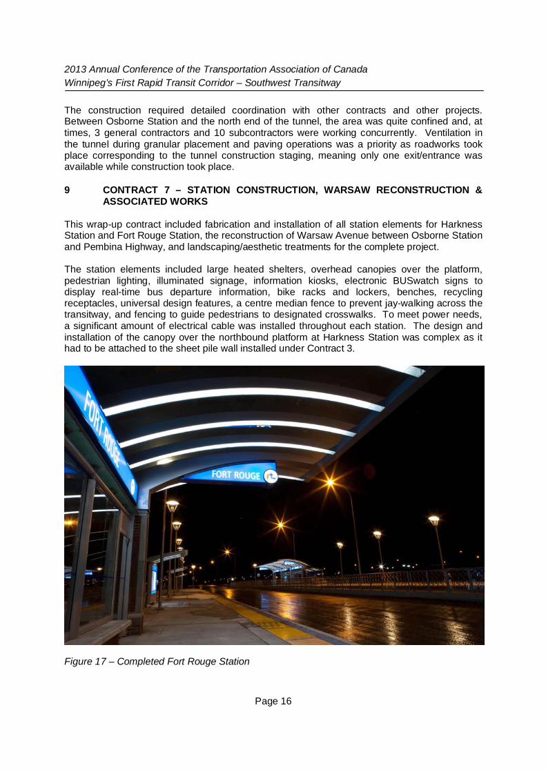
This wrap-up contract included fabrication and installation of all station elements for HarknessStation and Fort Rouge Station, the reconstruction of Warsaw Avenue between Osborne Stationand Pembina Highway, and landscaping/aesthetic treatments for the complete project.
The station elements included large heated shelters, overhead canopies over the platform,pedestrian lighting, illuminated signage, information kiosks, electronic BUSwatch signs todisplay real-time bus departure information, bike racks and lockers, benches, recyclingreceptacles, universal design features, a centre median fence to prevent jay-walking across thetransitway, and fencing to guide pedestrians to designated crosswalks. To meet power needs,a significant amount of electrical cable was installed throughout each station. The design andinstallation of the canopy over the northbound platform at Harkness Station was complex as ithad to be attached to the sheet pile wall installed under Contract 3.
Figure 17 – Completed Fort Rouge Station

2013 Annual Conference of the Transportation Association of CanadaWinnipeg’s First Rapid Transit Corridor – Southwest Transitway
Page 17
In addition to the station works, a substantial amount of roadwork was also included. Theroadway works included the construction of links between the transitway and the street system;these were left unfinished until the end of the project to discourage motorists from inadvertentlyaccessing the transitway during construction. Being the final of seven, this contract was seenas the completion contract. The two major areas of roadwork included within this project are atthe northern most extent of the transitway at Queen Elizabeth Way and at the Warsaw Streetaccess at the convergence of Contracts 4, 5, and 6. As mentioned in the description of Contract6 works, this small physical area had up to ten separate contractors working at any given time.Coordination of separate contracts and communication amongst contractors was vital forsuccess in this area.
The Warsaw work also involved the reconfiguration and reconstruction of the Pembina &Warsaw intersection, including new traffic signals to accommodate bus turning movementsto/from Pembina Highway. Physical work involved pavement reconstruction from PembinaHighway to the Manitoba Hydro substation immediately adjacent to the Osborne Station. Thisentailed removal of existing pavements, excavation, minimal land drainage sewer works,limestone sub-base placement, and concrete paving. Similar to Contracts 3 and 6, a concretedepth of 230 mm was utilized. The intersection at Pembina Highway and Warsaw Avenue alsowitnessed significant upgrades, including a left turn lane addition for southbound transit buseswishing to access the transitway via Warsaw, and signalization of the intersection to facilitatetransit movements to and from the transitway.
At the northern end of the transitway at Queen Elizabeth Way, traffic islands and roadway laneswere realigned to provide proper channelization for southbound buses to enter the transitwayand traffic signal upgrades were implemented to accommodate the new patterns of bus, traffic,cycling, and pedestrian movements.
10 ACTIVE TRANSPORTATION
Although the main focus of the Southwest Transitway was to provide improved transitinfrastructure, equally important was the opportunity to improve active transportation facilities,thus designing a system that supports active, accessible and healthy lifestyle options. Tosupport the City’s development of its AT network, several Active Transportation Paths (ATP)were constructed:
A major upgrade of the South Winnipeg Parkway ATP (along the west bank of the RedRiver between The Forks/Queen Elizabeth Way and Osborne & Glasgow)
ATP through the Fort Rouge Yards between Osborne & Glasgow and Jubilee Avenue ATP linking the Assiniboine Avenue Cycle Track, Queen Elizabeth Way, Harkness
Station, and Osborne Station via Stradbrook Avenue and Donald Street Canopy-protected bike racks and bike lockers at Harkness, Osborne, Fort Rouge
Stations
Planning considerations (connectivity, accessibility, safety, public/private property implications,flood protection impacts, etc.) and engineering considerations (i.e. City of Winnipeg and ATPdesign standards, implications for existing infrastructure, structural requirements, CN clearancerequirements. transit and vehicular traffic impacts, etc.) were taken into account during theactive transportation analysis. The active transportation component includes bicycle storage atrapid transit stations and new paths that connect with existing Active Transportation Pathways(ATPs).

2013 Annual Conference of the Transportation Association of CanadaWinnipeg’s First Rapid Transit Corridor – Southwest Transitway
Page 18
The criteria used to identify and lay out routing options for the connection between the FortRouge ATP (Osborne Street shared sidewalk) and the Donald - Stradbrook ATP was based ona minimum 3.5 m wide multi-use paved path. Where that path width was not feasible, aminimum 3.0 m wide shared sidewalk was considered.
All identified options were laid out to meet the universally accessible standards of the City ofWinnipeg (City of Winnipeg 2006). Ramp layouts used a 5% slope where feasible, withlandings provided when ramps exceeded recommended distances. All options were developedso that they could be used by both commuting and recreational ATP users.
Safety considerations were twofold: general public safety; and Crime Prevention ThroughEnvironmental Design (CPTED) principles. General safety of the public and users of the ATPincluded such considerations as the potential conflict with vehicular traffic along roadways,transit vehicles on the transitway, and rail traffic on the CN mainline. It also includedconsiderations of inappropriate access to public or private spaces (i.e. ability to throw objectsfrom structures onto the transitway or CN mainline or otherwise access and vandalize property).
The second aspect of safety considered CPTED principles. Options were developed andevaluated on whether they created opportunities for ‘natural surveillance’ (i.e. clear sight linesfrom busy streets or public spaces) and provided ‘natural access control’ (i.e. clear exits andentrances).
Figure 18 – Bike Lockers outside Fort Rouge Station

2013 Annual Conference of the Transportation Association of CanadaWinnipeg’s First Rapid Transit Corridor – Southwest Transitway
Page 19
11 PROJECT SUMMARY
Winnipeg’s rapid transit network will have very positive socioeconomic impacts in terms ofincreased ridership, reduced traffic congestion, greenhouse gas reductions, improved access todowntown, and new transit oriented development opportunities in lands adjacent to stations.Although faced with extraordinary challenges of location, site conditions, constructioncomplexity, and an aggressive schedule, the unique mix of design ingenuity, technology, andequipment facilitated the efficient and safe completion of this first phase of the rapid transitnetwork. Stage 1 of the Southwest Transitway sets a high standard for further systemexpansion, provides an important new transportation option for Winnipeggers, is good for theenvironment, and will support Winnipeg’s future growth.
Figure 19 – Harkness Station