window cleaning equipment exterior building maintenance
TRANSCRIPT

CITY OF INGLEWOOD, CALIFORNIA
REQUEST FOR BIDS
WINDOW CLEANING EQUIPMENT EXTERIOR BUILDING MAINTENANCE (EBM) EQUIPMENT
FAÇADE ACCESS EQUIPMENT
RFB-0116 BIDS DUE:
October 9, 2019 at 11:30am
AT THE OFFICE OF
CITY CLERK LOCATED ON THE 1ST FLOOR
OF INGLEWOOD CITY HALL
One Manchester Blvd. Inglewood, CA 90301
MANDATORY PRE-BID CONFERENCE and site walk is scheduled for September 25, 2019 at 11:00 am .Please meet at City Hall, First (1st) Floor, Information Booth, One Manchester Blvd., Inglewood, California 90301
THE CITY WILL ONLY ACCEPT BIDS
FROM THE BIDDERS ATTENDING THE PRE-BID CONFERENCE MEETING AND SITE WALK
Contact Person During Bid Period:
Michael H. Tate, Purchasing and Contract Services Manager (310) 412-5266
1
RFB-0116 WINDOW CLEANING EQUIPMENT EXTERIOR BUILDING
MAINTENANCE (EBM) EQUIPMENT FAÇADE ACCESS EQUIPMENT
TABLE OF CONTENTS
1. INVITATION TO SUBMIT BIDS ............................................................................................... 3
2. QUESTIONS CONCERNING BID REQUIREMENTS………………………………………...4
3. SUBMISSION OF BID…………………………………………………………………………..4
4. SPECIAL PROVISION……………………………………………………………………….....5
5. DECLARATION OF THE BIDDER …….……………………………………………….…...34
6. EXTENSION OF CONTRACT TO OTHER PUBLIC AGENCIES………………………......35
7. NON-COLLUSION DECLARATION………………………………………………………...36
8. NO BID FORM…………………………………….…………………………………..……….37
9. SCOPE OF WORK……………..……………………………………………………………. ..38
DESIGN INSTRUCTIONS (Pages 34-41) STRUCTUAL STEEL FRAMING SPECIFICATIONS Section 051200 (Pages 42-46) CAST-IN-PLACE CONCRETE Section 033000 (Pages 47-59) DESIGN DEVELOPMENT DRAWINGS (Pages 60-71) 10. PROPOSAL AND STATEMENT PAGE………………………………………………..72
2


QUESTIONS CONCERNING BID REQUIREMENTS
All questions and issues related to bid requirements or information expected for each statement package should be made in writing to City to the attention of: (email preferred)
Michael Tate City of Inglewood
City Hall, 8th floor (Office of Purchasing and Contract Services Division) 1 Manchester Blvd. Inglewood, CA 90301
Telephone: (310) 412-5266 Fax: (310) 330-5766 Email Address: [email protected] The City of Inglewood will only communicate with one person per bid. It is the responsibility of the bidder to ensure that the City has the correct name and address of the contact person, phone number, and e-mail address. All changes to instructions to this RFB will be done through written addendum and posted on the City’s website. SUBMISSION OF BID
Written responses to the RFB must be prepared as specified above as to form, content, and sequence. Respondents should follow the checklist to ensure that all requirements are met. No changes to responses may be made after the submittal deadline.
• One original, ATTN: The Office of the City Clerk, received on or before, but no later October, 9 ,2019 at 11:30 am. Any responses received after this time will not be considered by the City.
• The response shall be signed by an officer, or officers, authorized to execute legal documents on behalf of the bidder and submitted to:
The Office of City Clerk City of Inglewood 1st Floor
1 Manchester Blvd, Inglewood, CA 90301 The envelope shall be plainly marked in the upper left-hand corner with the name and address of the vendor and bear the words "Bid For..." followed by the name of the work under this Request for Bid and the date and hour of the bid opening.
The City reserves the right to waive informalities in any bid, to reject any or all bids, to reject one part of a bid and accept the other, except to the extent that bids are qualified by specific limitations, and to make awards to the lowest responsible bidder. Each firm is responsible for the timely delivery of any response. Additionally, the City will not be responsible for the delivery of any bid to the wrong address or City department. Each firm assumes all risks and/or consequences of an incorrect delivery or an untimely delivery of a bid.
4

SPECIAL PROVISIONS
TABLE OF CONTENTS Page
Section 1. DEFINITIONS .................................................................................................. 7
Section 2. CONTRACT DOCUMENTS ............................................................................. 7
Section 3. PICKUP OF PLANS AND SPECIFICATIONS .................................................. 7
Section 4. PRECEDENCE OF CONTRACT DOCUMENTS .............................................. 8
Section 5. THE PROPOSAL .............................................................................................. 8
Section 6. LOWEST RESPONSIBLE BIDDER ................................................................. 9
Section 7. BIDDER'S BOND .............................................................................................. 9
Section 8. CONSTRUCTION BOND ............................................................................... 10
Section 9. RETENTION .................................................................................................. 10
Section 10. INGLEWOOD BUSINESS TAX CERTIFICATE .......................................... 10
Section 11. LIABILITY INSURANCE ............................................................................. 10
Section 12. INDEMNIFICATION .................................................................................... 12
Section 13. PREVAILING WAGE AND OTHER LABOR CODE REQUIREMENTS .... 13
Section 14. NOTICE OF REQUIREMENT TO REGISTER TO SUBMIT BID OR
PERFORM WORK ON PUBLIC WORK PROJECT PURSUANT TO
LABOR CODE SECTION 1771.1 ................................................................. 14
Section 15. NONDISCRIMINATION IN EMPLOYMENT ............................................. 14
Section 16. SUBCONTRACTS ........................................................................................ 15
Section 17. AUTHORITY OF THE ENGINEER .............................................................. 15
Section 18. CHANGE ORDERS ...................................................................................... 15
Section 19. SERVICE OF NOTICE ................................................................................. 16
Section 20. WORK DONE BY OTHERS ......................................................................... 16
Section 21. PERMITS AND INSPECTION COSTS ......................................................... 16
Section 22. LOCAL CONDITIONS ................................................................................. 17
Section 23. "OR EQUAL" CLAUSE ................................................................................ 17
Section 24. SCOPE OF WORK ....................................................................................... 17
Section 25. RIGHTS-OF-WAY ........................................................................................ 18
Section 26. USE OF IMPROVEMENT DURING CONSTRUCTION ............................... 18
Section 27. EXECUTION OF CONTRACT ..................................................................... 19
Section 28. CONSTRUCTION SCHEDULE .................................................................... 19
5

Section 29. COMPLETION AND ACCEPTANCE ........................................................... 19
Section 30. TERMINATION OF CONTRACT ................................................................ 19
Section 31. TIME OF COMPLETION ............................................................................. 19
Section 32. LIQUIDATED DAMAGES ............................................................................ 20
Section 33. NOTIFICATION OF START OF WORK ...................................................... 20
Section 34. RECORD DRAWINGS ................................................................................. 20
Section 35. SUPERINTENDENTS ................................................................................... 20
Section 36. NOISE ABATEMENT ................................................................................... 20
Section 37. CLEANUP AND DUST CONTROL ............................................................... 20
Section 38. WATER FOR CONSTRUCTION .................................................................. 21
Section 39. EXISTING UTILITY LINES ......................................................................... 22
Section 40. TRAFFIC AND ACCESS .............................................................................. 23
Section 41. RIGHT OF CITY TO WITHHOLD PAYMENT ............................................ 23
Section 42. FINAL PAYMENT TERMINATES LIABILITY ........................................... 24
Section 43. CLAIMS AND PROTESTS ........................................................................... 24
Section 44. GUARANTEE ............................................................................................... 25
Section 45. ADDITIONAL REFERENCES ...................................................................... 25
Section 46. SURVEY WORK AND PRESERVATION OF SURVEY MONUMENTS ...... 26
Section 47. KEY POLICY FOR CITY FACILITIES ........................................................ 26
Section 48. CONSTRUCTION WASTE DISPOSAL CONTAINER ................................. 27
Section 49. CLEAN WATER ACT COMPLIANCE ......................................................... 27
Section 50. CONSTRUCTION & DEMOLITION DIVERSION PROGRAM PERMIT
AND REPORTS .......................................................................................... 27
Section 51. STAGING AREAS FOR CONSTRUCTION .................................................. 27
Section 52. ADDENDUMS (REVISIONS TO THIS DOCUMENT) ................................... 28
Section 53. CHOICE OF LAW AND VENUE ................................................................... 28
6

SPECIAL PROVISIONS
Except as otherwise provided in the Special Provisions, Scope of Work Specifications, or as modified herein, the work embraced herein shall be done in accordance with the appropriate provisions of the Standard Specifications for Public Works Construction, Latest Edition, which are hereinafter referred to as the Standard Specifications. The intention of the Contract Documents is to include all plant labor, services, materials, tools, equipment, supplies, transportation, utilities, and all other items and facilities necessary therefore, as provided in the Contract Documents for the proper execution and completion of the work on the Project in strict accordance with the Plans and Specifications.
Section 1. DEFINITIONS Whenever in the Specifications the following terms are used, they shall be understood to mean and refer to the following: AGENCY: CITY OF INGLEWOOD BOARD: CITY COUNCIL of the CITY OF INGLEWOOD CONSULTANT: The designated Consultant authorized by the Agency to represent the CITY (if applicable) Other terms appearing in the Standard Specifications shall have the intent and meaning specified therein.
Section 2. CONTRACT DOCUMENTS The Contract Documents are comprised of the following, including all additions, deletions, modifications, appendices, and all addenda as prepared prior to the date of bid opening setting forth modifications or interpretations of any of said Documents: The Invitation to Submit Bids, the Instructions to Bidders, the accepted Proposal, the List of Subcontractors, the Bid Security Forms, the Agreement, the Faithful Performance Bond, the Labor & Materials Bond, , the Plans (if any), Scope of Work Specifications, and these Special Provisions.
Section 3. PICKUP OF PLANS AND SPECIFICATIONS The Plans and Specifications and all other Documents comprising the pertinent Contract Documents, may be obtained at the Purchasing Division on the Eighth Floor of Inglewood City Hall, One Manchester Boulevard, Inglewood, CA, 90301.
7

Section 4. PRECEDENCE OF CONTRACT DOCUMENTS The order of precedence of Documents shall be: FIRST: Requirements of law, including the Charter and Ordinances of the City. SECOND: Permits from other Agencies as may be required by law or Ordinance. THIRD: Permits from City Departments as may be required by law or
Ordinance. FOURTH: Change Orders and/or Supplemental Agreements; whichever occurs
last. FIFTH: Contract/Agreement. SIXTH: Addenda. SEVENTH: Bid/Proposal. EIGHTH: Special Provisions. NINTH: Plans with detail drawings.
Section 5. THE PROPOSAL Proposals shall be submitted on the form provided by the City and shall be enclosed in a sealed envelope, marked, and addressed as hereinafter directed. The Bidder shall state in words and figures the specific sum for which he/she proposes to supply the labor, materials, supplies, or machinery, and perform the work required by the Plans and Specifications (Including all taxes and fees). In case words and figures do not agree, the words shall govern and the figures shall be disregarded. If the Proposal is made by an individual, it shall be signed and his/her full name and address shall be given; if it is made by a firm, it shall be signed with the co-partnership name by a member of the firm who shall also sign his/her own name and the name and address of each member shall be given; if it is made by a corporation, the name of the corporation shall be signed by its duly authorized officer or officers, attested by the corporate seal, and the names and titles of all officers of the corporation shall be given. No telegraphic proposal or telegraphic modification of the Proposal will be considered. Blank spaces in the Proposal shall be properly filled. The phraseology of the Proposal must not be changed and no additions shall be made to the items mentioned therein. Unauthorized conditions, limitations, or provisions attached to the Proposal will render it informal and may cause its rejection. Alterations by erasure or inter-lineation must be explained or noted in the Proposal over the signature of the Bidder. Alternative proposals will not be considered unless specifically provided for in the Bidding Sheet. A bidder may withdraw their proposal before the hour fixed for opening bids without prejudice to themselves by submitting a written request to the City Clerk for its withdrawal and the Proposal will be returned to him/her unopened when reached in the procedure of opening bids. No proposals may be withdrawn after the hour fixed for opening bids without rendering the accompanying bidder's bond, or certified or cashier check, or cash guaranty subject to forfeiture or liquidated damages in like manner as in the case of failure to execute contract after award, as hereinafter
8
provided. No proposal received after the time named or at any place other than the place stated in the Invitation to Submit Bids will be considered. All bids will be opened and declared publicly. Bidders, their representatives, and others interested are invited to be present at the opening. The City reserves the right to waive informality in any bid, to reject any or all proposals, to reject one part of a proposal and accept the other, except to the extent that bids are qualified by specific limitations, and to make awards to the lowest responsible bidder as the interest of the City may require. Any proposal which is so unbalanced between the various contract items as to be detrimental to the interests of the City may also be rejected. Where bonds are required, the bidder shall name in his/her proposal the Surety or Sureties which have agreed to furnish said bonds. The envelope enclosing the Proposal shall be sealed and addressed to the City Clerk, City of Inglewood, One Manchester Boulevard, Inglewood, CA, 90301. The envelope shall be plainly marked in the upper left-hand corner with the name and address of the bidder and bear the words "Proposal For..." followed by the name of the work and the date and hour of bid opening.
Section 6. LOWEST RESPONSIBLE BIDDER Section 2-200 of the Inglewood Municipal Code states: "The expression 'lowest responsible bidder' as used in this Article and the City's bidding documents shall be deemed to mean the lowest bidder whose offer best responds in quality, fitness, and capacity to the requirements of the proposed work or usage." In selecting the lowest responsible bidder, consideration will be given not only to the financial standing, but also to the general competence of the Bidder for the performance of the work covered by the Proposal. To receive favorable consideration, a bidder must present evidence that he/she has successfully performed similar work of comparable magnitude or submit other evidence satisfactory to the City that he/she or their associates are personally competent to manage the proposed undertaking and to carry it forward to a successful conclusion. Professional integrity and honesty of purpose shall be essential requirements. A showing of adequate financial resources is required, but will not alone determine whether a bidder is competent to undertake the proposed work. Each bidder must furnish, if required, a record of past performance and experience and show that his/her organization, capital, and equipment are adequate for the successful prosecution of the required work and its completion within the time specified.
Section 7. BIDDER'S BOND As a guaranty of good faith, each bidder shall submit with their proposal an unconditional Bidder's Bond or Certified or Cashier's Check, drawn on a solvent State or National bank, or cash in the sum stated in the Invitation to Submit Bids, payable to the “City of Inglewood,” said Bidder's Bond or check to be held uncollected until it becomes subject to disposal as herein provided. Any condition or limitation placed upon said Bidder's Bond or check will render it informal and may, at the option of the City, result in the rejection of the Proposal under which such Bidder's Bond or check is submitted. If a bidder to whom an award is made fails or refuses to execute the Contract and furnish the required bonds, all within the time stated, said Bidder's Bond or check and the monies represented thereby, or the cash guaranty, shall be and remain the property of the City and shall be subject to deposit with the Treasurer of the City as other monies belonging to the City, the amount thereof being agreed to by the Bidder as liquidated damages due the City. Within fifteen (15) days after the award of the Contract, the City will return the Proposal guarantees accompanying such as the Proposals, which are not to be considered in making the award. All other proposal guarantees will be
9

held until the Contract has been finally executed, after which they will be returned to the respective bidders whose proposal they accompany.
Section 8. CONSTRUCTION BOND Per Section 2-196 of the Inglewood Municipal Code, the Contractor agrees to at all times during the performance of the agreement obtain, keep, and maintain a Faithful Performance Bond in the amount of the Contract Sum, and a Contractor's Labor and Material Bond in the amount of the Contract Sum. Said bonds shall be in the form approved by the City Attorney and Surety on all bonds furnished must be satisfactory to the City.
Section 9. RETENTION Provisions of California Public Contract Code §22300 et. seq., substitution of eligible and equivalent securities for retention held by the City to ensure the Contractor’s performance under this Agreement will be permitted at the request and expense of the Contractor and in conformity with California Public Contract Code§22300. The forgoing notwithstanding, the Contractor shall have ten (10) days following action by the City to award the Agreement to the Contractor to submit its written request to the City to permit the substitution of securities for retention under California Public Contract Code §22300. The failure of such Contractor to make such written request to the City within said ten (10) day period shall be deemed a waiver of the Contractor’s rights under California Public Contract Code §22300. In the event the Contractor wishes to choose to exercise its rights under California Public Contract Code §22300, the Contractor shall enter into an escrow agreement with the City, and the escrow agent, a state or federally chartered bank in California with a current A.M. Best Rating of not less than “A”, in the form specified by said Section 22300. Contractor shall have the obligation of ensuring that such securities deposited are sufficient to maintain, in total fair market value, an amount equal to the cash amount of the sums to be withheld under the Agreement. If upon written notice from City or from the appropriate escrow agent, indicating that the fair market value of the securities has dropped below the dollar amount of monies to be withheld by City to ensure performance, Contractor shall, within five (5) days of the date of such notice, post additional securities as necessary to ensure that the total fair market value of all such securities held by City, or in escrow, is equivalent to the amount of money to be withheld by City under the Agreement.
Section 10. INGLEWOOD BUSINESS TAX CERTIFICATE The bidder agrees to, at all times during the performance of the agreement, obtain and maintain an Inglewood City Business Tax Certificate. The Certificate must be obtained prior to the of performance of services and a copy forwarded to the Purchasing and Contracts Services Division.
Section 11. LIABILITY INSURANCE
The Contractor shall furnish the City with Comprehensive General Liability Insurance including automobile, contractual liability, products, and completed operations, owner's protective and personal injury coverage, in which the City is named as an additional insured, with the Contractor's insurance to be primary. Any insurance in effect protecting the City shall be excess and shall be effective only upon exhaustion of Contractor's insurance. The Policy shall insure the City, its officials, officers, employees, agents and volunteers, while acting within the scope of their duties, against all claims arising out of or in connection with the work, except as provided for in Section 25 of these Special Provisions. The Policy or endorsement shall state clearly that the City shall be notified by registered mail at least thirty (30)
10

days prior to cancellation of the Policy for any reason.
Minimum Scope of Insurance
Coverage shall be at least as broad as:
1. Insurance Services Office Commercial General Liability Coverage (occurrence Form CG0001).
2. Insurance Services Office Form Number CA0001 covering Automobile Liability, Code 1
(any auto).
3. Workers’ Compensation Insurance as required by the State of California and Employer’s Liability Insurance.
Minimum Limits of Insurance The Contractor shall maintain these policies and shall cause all parties supplying services, labor, or materials to maintain the following insurance in amounts not less than those specified below: 1. General Liability: $1,500,000
(including operations, products, and completed operations)
Per occurrence for bodily injury, personal injury, and property damage. If Commercial General Liability Insurance or other form with a general aggregate limit is used, either the general aggregate limit shall apply separately to the Project/location OR the general aggregate limit shall be twice the required occurrence limit ($2,000,000). The "City of Inglewood, its officials, officers, employees, agents, and volunteers" must be separately endorsed to the policy as additional insured’s on an endorsement equivalent to the Insurance Services Office, Inc. (ISO) forms CG 20 10 11 85 or CG 20 26 11 85.
2. Automobile Liability: $1,500,000 Per accident for bodily injury and property damage covering Auto symbol 1 (Any auto).
3. Worker’s Compensation and Employer’s Liability: $1,500,000
Per accident for bodily injury or disease.
Deductibles and Self-Insurance Retentions
Any deductibles or self-insured retentions must be declared to and approved by the City Attorney. At the option of the City, either: the Insurer shall reduce or eliminate such deductibles or self-insured retentions as respects the City, its officers, officials, employees, agents and volunteers; or the Contractor shall provide a financial guarantee satisfactory to the City Attorney guaranteeing payment of losses and related investigations, claims administration, and defense expenses.
Other Insurance Provisions The Commercial General Liability and Automobile Liability policies are to contain, or be endorsed to
11

contain, the following provisions:
1. The City, its officers, officials, employees, agents and volunteers are to be covered as insured with respect to liability arising out of automobile owned, leased, hired, or borrowed by, or on behalf of, the Contractor: and with respect to liability arising out of work or operations performed by, or on behalf of, the Contractor, including materials, parts, or equipment furnished in connection with such work or operations. General liability coverage can be provided in the form of an endorsement to the Contractor’s insurance, or as a separate owner’s policy (CG 20 10 11 85).
2. For any claims related to this project, except as provided in Section 19 of the Special
Provisions, the Contractor’s insurance coverage shall be primary insurance as respects the City, its officers, officials, employees, agents and volunteers. Any insurance or self-insurance maintained by the City, its officers, officials, employees, or volunteers shall be excess of the Contractor’s insurance and shall not contribute with it.
3. Each insurance policy required by this clause shall be endorsed to state that coverage shall
not be canceled by either party, except after thirty (30) days prior written notice by Certified Mail, return receipt requested, has been given to the City.
4. Coverage shall not extend to any indemnity coverage for the active negligence of the
additional insured in any case where an agreement to indemnify the additional insured would be invalid under Subdivision (b) of Section 2782 of the Civil Code.
Acceptability of Insurers Insurance is to be placed with insurers with a current A.M. Best Company’s rating of no less that A:VII.
Verification of Coverage The Contractor shall furnish the City with original certificates and amendatory endorsements effecting coverage required to conform to the insurance requirements. All certificates and endorsements are to be received and approved by the City Attorney’s office before work commences. The City reserves the right to require complete, certified copies of all required insurance policies, including endorsements affecting the coverage required by these Special Specifications at any time. The Contractor shall include all subcontractors as insured under its policy.
Section 12. INDEMNIFICATION The Contractor shall indemnify and hold harmless the City and its officials, officers, employees, agents and volunteers (collective Indemnities) from and against all claims, damages, losses, and expenses, including attorney fees arising out of the performance of the work described herein, caused in whole or part by any negligent act or omission of the Contractor, any subcontractor, anyone directly or indirectly employed by any of them, or anyone for whose acts any of them may be liable, except where caused by the active, sole negligence, or willful misconduct of the City. If any action or proceeding is brought against Indemnities by reason of any act of the matters against which the Consultant has agreed to indemnify Indemnities as provided above, the Contractor, upon notice from the City, shall defend Indemnities at the Contractor’s expense by counsel acceptable to the
12

City, such acceptance not to be unreasonably withheld. Indemnities need not have first paid for any of the matters to which Indemnities are entitled to indemnification in order to be indemnified. The insurance required to be maintained by the Contractor under this Article shall ensure the Contractor’s obligations under this Section, but the limits of such insurance shall not limit the liability of the Contractor hereunder. The provisions of this Article shall survive the expiration or earlier termination of this Agreement.
Section 13. PREVAILING WAGE AND OTHER LABOR CODE REQUIREMENTS This is a public works project subject to the requirements of California Labor Code section 1720 et seq. and Inglewood Ordinance No. 15-05, requiring the payment of prevailing wages, training of apprentices and compliance with other applicable requirements of the Labor Code. Prevailing wages apply to all projects over $1,000, which are defined as a “public work” in the Labor Code. Contractors are reminded that the Labor Code requires a public works contract awarded by the City to contain language effectuating certain sections of the Code, including 1775, 1776, 1775.5, 1810, 1813, and 1860. Furthermore, any contract between a contractor and its subcontractors for the performance of work on a public works project shall include a copy of the provisions of Labor Code sections 1771, 1775, 1776, 177.5, 1813 and 1815. Below is a summary of these requirements. 1. Prevailing Wage Pursuant to Labor Code section 1773.2, the general prevailing rate of per diem wages for this project are on file in the City Clerk’s Office and will be made available to any interested party upon request. Contractor shall post a copy of applicable prevailing wage determination at each job site. The contractor who is awarded a public works contract, and any subcontractor under the contractor, shall pay not less than the specified prevailing rate of wages. Special prevailing wage rates generally apply to work performed on weekends, holidays and for certain shift work. Contractors and subcontractors are on notice that information about such special rates, holidays, premium pay, shift work and travel and subsistence requirements can be found on the Department of Industrial Relations website (www.dir.ca.gov). 2. Certified Payroll Records Contractor and their subcontractors must maintain certified payroll records in compliance with Labor Code sections 1776 and 1812, and any implementing regulations promulgated by the Department of Industrial Relations. The payroll records shall include the name, address, social security number, work classification, straight time and overtime hours worked each day and week, and the actual per diem wages paid to each journeyman, apprentice, worker, or other employee employed by the contractor or subcontractor in connection with the public work. Certified payroll records must be available for inspection at reasonable hours at the principal office of the contractor with any personal identifying information redacted as required by law. As a condition to receiving progress payments, final payment and payment of retention on any and all projects on which the payment of prevailing wages is required, the contractor agrees to present to the City, along with its request for payment, all applicable and necessary certified payrolls (for itself and all applicable subcontractors) for the time period covering such payment request.
4. Apprentices Pursuant to Labor Code section 1777.5(c), “[o]nly apprentices, as defined in Section 3077, who are in training under apprenticeship standards that have been approved by the Chief of the Division of Apprenticeship Standards and who are parties to written apprenticeship agreements under Chapter 4 (commencing with Section 3070) of Division 3 are eligible to be employed at the apprentice wage rate on public works.” Apprentices who are not properly supervised and employed in the appropriate ratio shall be paid the full journeyman wage for the classification of work performed. These apprentice requirements apply
13

to any contract worth $30,000 or more. It is the prime contractor’s responsibility to comply with all of the requirements contained in section 1777.5 and any contract for public works awarded to a prime contractor shall include language effectuating this section. 4. Work Day Pursuant to Labor Code section 1810, 8 hours of labor constitutes a legal day’s work and 40 hours of labor constitute a legal week’s work. Contractor and its subcontractors shall not permit any of their workers to perform more than 8 hours of work during any one calendar day or more than 40 hours of work during any one week, unless overtime is paid in accordance with Labor Code section 1815. Contractor and each subcontractor shall keep accurate records showing the name and actual hours worked each calendar day and each calendar week by each worker employed in connection with this public works project. These records shall be kept open at all reasonable hours for inspection by the City and the Division of Labor Standards Enforcement. 5. Workers’ Compensation In accordance with the provisions of Labor Code section 3700, every contractor will be required to secure the payment of compensation to his or her employees. Each contractor to whom a public works contract is awarded shall sign and file with the City the following certification prior to performing the work of the contract: “I am aware of the provisions of Section 3700 of the Labor Code which require every employer to be insured against liability for workers’ compensation or to undertake self-insurance in accordance with the provisions of that code, and I will comply with such provisions before commencing the performance of work of this contract.” 6. Penalties Penalties, including forfeitures and debarment, shall be imposed for any contractor or subcontractor’s failure to pay prevailing wages, failure to maintain and timely submit accurate certified payroll records upon request, failure to employ apprentices, and failure to pay employees for all hours worked at the correct prevailing wage, in accordance with Labor Code sections 1775, 1776, 1777.7 and 1813.
Section 14. NOTICE OF REQUIREMENT TO REGISTER TO SUBMIT BID OR PERFORM WORK ON PUBLIC WORK PROJECT PURSUANT TO LABOR CODE SECTION 1771.1 Pursuant to Labor Code section 1771.1, a contractor or subcontract may not be qualified to bid on, be listed in a bid proposal, or engage in the performance of any contract for public work unless currently registered and qualified to perform public work pursuant to section 1725.5. Section 1725.5 does not apply to work performed on a public works project of $25,000 or less when the project is for construction, alteration, demolition, installation, or repair work or to work performed on a public works project of $15,000 or less when the project is for maintenance. Unless otherwise exempt by state law, a bid shall not be accepted nor any contract or subcontract entered into without proof of the contractor or subcontractor’s current registration to perform work pursuant to Section 1725.5 of the Labor Code. Contractor and subcontractors who violate the requirements of Section 1771.1 shall be subject to penalties as prescribed therein.
Section 15. NONDISCRIMINATION IN EMPLOYMENT Contractor shall comply with all applicable laws prohibiting discrimination in the employment of persons and shall be subject to all punishment for any violation thereof. These prohibitions may be found in Labor Code sections 1735 and 1777.6, and Title VII of the Civil Rights Act of 1964, as amended. Labor Code section 1735 provides that “contractor shall not discriminate in the employment of persons
14

upon public works on any basis listed in subdivision (a) of Section 12940 of the Government Code, as those bases are defined in Sections 12926 and 12926.1 of the Government Code, except as otherwise provided in Section 12940 of the Government Code. Every contractor for public works who violates this section is subject to all penalties imposed for a violation of this chapter.” Labor Code section 1777.6 provides that an “employer or labor union shall not refuse to accept otherwise qualified employees as registered apprentices on any public works on any basis listed in subdivision (a) of Section 12940 of the Government Code, as those bases are defined in Sections 12926 and 12926.1 of the Government Code, except as provided in Section 3077 of this code and Section 12940 of the Government Code.”
Section 16. SUBCONTRACTS The Engineer shall have the authority to approve changes of, or additions of, subcontractors. Such permission shall be requested in writing and must be approved in writing. Nothing contained in the Contract Documents shall be held to create a direct contractual relationship between any subcontractor and the City. No subcontractor will be recognized as such; all persons engaged in the work of construction will be considered as employees of the Contractor, and the Contractor will be held responsible for their work, which shall be subject to all the Provisions of the Contract Documents.
Section 17. AUTHORITY OF THE ENGINEER All work of the Contract will be supervised by the Engineer. References to "Engineer" which concern administrative aspects of the Contract including provisions for time for commencing and completing work and extension of time shall be understood literally as meaning the Engineer or an authorized representative. The Engineer shall have the authority to give such general directions and exercise such control as may be necessary to ensure that work on the Project is in strict compliance with the Contract Documents. The Engineer shall determine the adequacy of the Contractor's methods, plant, and equipment, and may issue such directions relative to the sufficiency of forces as may be reasonably necessary to ensure proper and continuous execution of the work. The Engineer shall have the authority to stop the work, if necessary, to prevent its improper execution and shall determine the amount, quality, and fitness of the several kinds of work. The Engineer shall have the authority to reject all work which does not conform to the requirements of the Contract and shall have power to make such other decisions as provided in these Specifications. All instructions, rulings, and decisions of the Engineer shall be final and binding unless formal protest is made under the Provisions for "Claims and Protests" in Section 3 3 of these Specifications. The Engineer shall have executive authority to enforce such decisions and orders, which the Contractor shall carry out promptly. The Engineer shall have the authority to issue change orders not to exceed ten percent (10%) of the Contract amount, and time extensions as he/she deems necessary to best serve the City's interests.
Section 18. CHANGE ORDERS All administrative aspects involving change orders shall be authorized by Public Works Director/City Engineer or Project Manager.
15

Section 19. SERVICE OF NOTICE The delivering of any notice, instruction, claim, protest, or other written communication, personally to the Contractor or a representative on the Project, to the Engineer or a representative on the Project, or to the City or its representative at his/her office or legal place of business, shall constitute service thereof upon the Contractor, the Engineer, or the City, respectively. The depositing in a post-paid wrapper directed to the official address of the Contractor, the Engineer, or the City, in any post office box regularly maintained by the protestor, or other written communication, shall be deemed sufficient service thereof upon the Contractor, the Engineer, or the City, respectively, and the date of such service shall be considered to be the day following the date of such mailing. The official address of the Contractor shall be the address given in the accepted Proposal or such other address as the Contractor may subsequently designate in writing to the Engineer and the City. The official address of the City shall be: City of Inglewood; City Clerk's Office; One Manchester Boulevard; Inglewood, CA, 90301.
Section 20. WORK DONE BY OTHERS The City reserves the right to do other work and to let other contracts for work contiguous to the work set forth in the Contract Documents. In the event that work is done by the City or by other contractors contiguous to the work covered by this contract, the respective rights of the various interest involved shall be established by the Engineer. The Contractor shall afford the City and other contractors reasonable opportunity for the introduction and storage of their materials and for the execution of their work, and shall properly conduct and coordinate work with all other parties. If any part of the work under this contract depends for proper execution or result upon any other contiguous work, the Contractor shall inspect such work and promptly report to the Engineer any condition which may adversely affect the work under this contract. The Contractor’s failure to inspect and report same shall constitute an acceptance of said other contiguous work as fit and proper for the reception of the work under this contract, except as to deficiencies which may develop in said other work after the execution of the work covered under this contract.
Section 21. PERMITS AND INSPECTION COSTS Wherever the property of the Federal Government, the State of California, the County of Los Angeles, the City of Inglewood, any local utilities, or of any other agency affected by the work included in this contract, the Contractor shall bear the cost of all permits and inspection lawfully exacted by said Government, State, County, City, District, Department, or other agency during the time of performing the work affecting said property; also, the Contractor shall bear all cost of traffic regulation and traffic control devices lawfully exacted by said State, County, City, or other agency during the time of performing the work affecting said property. When working within the Railroad’s right of way, the Contractor shall contact Burlington Northern Santa Fe (BNSF) and/or Metropolitan Transportation Agency (MTA) and bear all cost of traffic regulation and traffic control during the time performing the work affecting said property.
16

Where required under the terms of the permits, the Contractor shall obtain liability insurance acceptable to and in an amount required by the public agency having jurisdiction. The policy shall insure said agency against all claims arising out of or in connection with the work to be performed and shall remain in full force and effect until the work is accepted by the City. The Contractor shall furnish to each such agency a certificate of protective liability insurance showing the protection afforded and the amount thereof. Neither the terms hereof nor anything shown on the Drawings in connection with rights-of-way provided by the City shall be construed to entitle the Contractor to conduct operations in said rights-of-way in violation of existing regulations restricting interference with watercourses and drainage channels. The Contractor shall take adequate precautions against obstructing storm water flow in any affected watercourse or channel, and shall not deposit excavated materials in any area where they might interfere with or be subject to erosion from such flow.
Section 22. LOCAL CONDITIONS Bidders shall read the Specifications, examine the Drawings, and make their own estimates of the existing facilities and the difficulties, which will attend the execution of the work called for by the proposed contract, including local conditions, uncertainty of weather, and all other contingencies. Bidders shall satisfy themselves by personal examination of the location of the proposed work and by such other means as they may choose so as to determine the actual conditions and requirements. Information derived from the maps, profiles, Plans and Specifications, Drawings, City Personnel, the Consultant, or his/her assistants, shall not relieve the Bidder of this responsibility.
Section 23. "OR EQUAL" CLAUSE Whenever a material, article, or piece of equipment is identified on the Plans or in the Specifications by reference to manufacturers' or vendors' names, trade names, catalogue numbers, etc., it is intended merely to establish a standard; and any material, article, or equipment of other manufacturers’ and vendors’ which will perform adequately the duties imposed by the general design, shall be considered equally acceptable provided the material, article, or equipment so proposed is, in the opinion of the Engineer, of equal substance and function. Said materials, articles, or equipment shall not be purchased or installed by the Contractor without the Engineer's written approval.
Section 24. SCOPE OF WORK The work to be performed under this contract shall consist of furnishing all plans, tools, equipment, materials, supplies, and manufactured articles, and for furnishing all transportation and services, including fuel, power, water, and essential communications, and for the performance of all labor, work, or other operations required for the fulfillment of the Contract in strict accordance with the Specifications, Drawings, schedules, and other Contract Documents, as herein before defined, all of which are made a part hereof, and including such detail sketches as may be furnished by the Engineer from time to time during construction in explanation of said Drawings. The work shall be complete, and all work, materials, and services not expressly called for in the Specifications or not shown on the Drawings, which may be necessary for the complete and proper construction of the work, in good faith shall be performed, furnished, and installed by the Contractor as though originally so specified or shown, at no increase in cost to the City. The Contractor shall check all dimensions and quantities on the Drawings or schedules herein contained or given by the Engineer, and shall notify the Engineer of all errors therein which may be discovered by examining and checking the Drawings. The Contractor shall not take advantage of any error or omission in these Specifications, or in the Drawings or schedules, but should such error or
17

omission be discovered, the Contractor shall obtain instructions from the Engineer and the Contractor shall carry out such instructions as if originally specified. The Contractor shall verify all dimensions in the field and shall check field conditions continuously during construction. The Contractor shall be solely responsible for any inaccuracies built into the work. The Contractor shall inspect related and appurtenant work and shall report in writing to the Engineer any conditions, which will prevent proper completion of the work. Any required removal, repair, or replacement caused by unsuitable conditions shall be done by the Contractor at his/her sole cost and expense.
Section 25. RIGHTS-OF-WAY Rights-of-way or easements as required for the prosecution of the work will be provided by the City. The Contractor shall be responsible for making their own arrangements for parking facilities, storage areas, and staging areas; the Contractor shall obtain written permission from the owners of the affected property for such use, and a copy of each such written permit shall be furnished to the City and property owners for their protection and records. The Contractor shall indemnify and hold the City harmless from all claims for damages occasioned by such actions.
Section 26. USE OF IMPROVEMENT DURING CONSTRUCTION The City reserves the right to take over and utilize all or parts of any completed facility or appurtenance. Such action by the City will relieve the Contractor of responsibility for injury or damage to said completed portions of the improvement resulting from use by public traffic or from the action of the elements or from any other cause except injury or damage resulting from the Contractor's operations or negligence. The Contractor will not be required to re-clean said utilized portions of the improvement before field acceptance, except for cleanup made necessary by their operations. Nothing in this Section shall be construed as relieving the Contractor from full responsibility for correcting defective work or materials. In the event the City exercises its right to place into service and utilize all or part of any completed facility or appurtenance, the City shall assume any responsibility and liability for injury to persons or property arising out of or resulting from the utilization of the facility or appurtenance so placed into service except for any such injury to person or property caused by any willful or negligent act or omission of the Contractor, subcontractor, their officers, employees, or agents. Notwithstanding the above, the City reserves all rights to use and maintain the public rights-of-way for pedestrian and vehicular traffic, except as may otherwise be provided in the Special Provisions. Such use of the public rights-of-way does not relieve the Contractor of any liability for damages to the improvements caused in whole or in part by the Contractor, any of his agents or subcontractors, or any other third party. Furthermore, such use of the public rights-of-way by City in no way constitutes acceptance of the work in whole or in part. The right is reserved to the City and to the owners of public utilities and franchises to enter at any time upon any public street, alley, right-of-way, or easement for the purpose of making changes in their property made necessary by the work of this contract.
18

Nothing herein shall be construed to entitle the Contractor to the exclusive use of any public street, alley, way, or parking area during the performance of the work hereunder and he shall so conduct his operations as not to interfere unnecessarily with the authorized work of utility companies or other agencies in such streets, alleys, ways, or parking areas.
Section 27. EXECUTION OF CONTRACT A bidder to whom award is made shall execute a written contract with the City and furnish good and approved bonds, if required in the Special Provisions all in accordance with the Provisions hereof and within the time stated in the Proposal. If a bidder to whom an award is made fails or refuses to enter into the Contract as herein provided or to conform to any of the stipulated requirements in connection therewith, the bid bond, check or cash guaranty shall become the property of the City as provided in Section 7 hereof, the award will be annulled and, in the discretion of the City, an award may be made to the Bidder whose proposal is next most acceptable to the City. Such bidder shall fulfill every stipulation embraced herein as if he/she were the party to whom the first award was made. A corporation to which an award is made will be required, before the Contract is finally executed, to furnish evidence of its corporate existence, of its rights to do business in California and of the authority of the officer signing the Contract and bonds for the corporation to so sign.
Section 28. CONSTRUCTION SCHEDULE The Contractor shall prepare and submit a complete construction schedule in a suitable form (i.e. “bar chart”) indicating starting time and completion of each subdivision of trade or work in the Project prior to start of work. The construction schedule shall be approved by the Engineer prior to commencement of construction. The construction schedule shall be submitted using Microsoft Project in 8.5”x11” – files schedule, and 24” x 32” wall schedule (if requested by City). Holidays and Fridays (every Friday City is closed) are “non-workdays.” Contractor will be provided a list of City Holidays. Contractor must receive prior approval before working on a “non-workday.” If work needs to be done on a non-workday, Contractor must submit a written request, to the Project Manager, at least 48 hours before the start of the work. If a request to work on a “non-workday” is approved, the Contractor shall compensate the City Inspector’s time at the following rates: Minimum six (6) hour inspection fee per day for Two Hundred and Seventy Dollars ($270), and Forty Five Dollars ($45) per hour, or portion thereof, thereafter. All work shall start after 8:00 a.m. and stop by 4:00 p.m. on regular working days.
Section 29. COMPLETION AND ACCEPTANCE It shall be within the area of responsibility of the City Engineer to make the final inspection of the work and to accept the completed work on behalf of the City.
Section 30. TERMINATION OF CONTRACT The City may terminate the Contract at its own discretion or when conditions encountered during the work make it impossible or impracticable to proceed, or when the Agency is prevented from proceeding with the Contract by law, or by official action of a public authority.
Section 31. TIME OF COMPLETION The Contractor shall complete the work within the time specified in the Proposal beginning with the date of the Notice to Proceed.
19

Section 32. LIQUIDATED DAMAGES It is agreed to by the parties to the Contract that in case all the work called for under the Contract is not completed before or upon the expiration of the time limit as set forth in these Specifications, damage will be sustained by the City, and that it is, and will be impracticable to determine the actual damage which the City will sustain in the event of and by reason of such delay; and it is, therefore, agreed that the Contractor will pay to the City the sum of seven hundred fifty dollars ($750) per day for each and every day's delay beyond the time prescribed to complete the work; and the Contractor agrees to pay such liquidated damages as herein provided, and in case the same are not paid, agrees that the City may deduct the amount thereof from any money due or that may become due the Contractor under the Contract.
Section 33. NOTIFICATION OF START OF WORK The Contractor shall notify the City of Inglewood Public Works Department Permit Section at (310) 412-5333, at least 48 hours prior to starting any construction within the street rights-of-way. The Contractor shall notify the Communications Center of the City at (310) 412-5251, at least 24 hours before commencing work. The Contractor shall formally notify, in writing, all residents and businesses that are located within a ½ mile radius from the construction site and/or are impacted by the construction work at least 72 hours before commencing work. Any and all correspondence to City Constituents shall be submitted no later than ten (10) working days for City Engineers approval prior to distribution. The Contractor shall also produce door knob hang tags containing general information related to the construction no later than ten (10) working days after receiving the Contract for City Manager’s approval. A sample shall be provided by the City.
Section 34. RECORD DRAWINGS The Contractor shall maintain at the job site a set of Plans and Specifications available at all times for inspection by the City, exclusively, and so marked for recording all changes in the work. The Contractor shall be responsible for seeing that any and all changes are recorded on this set each day. As Built drawing shall be submitted every payment request and before final payment.
Section 35. SUPERINTENDENTS The Contractor shall assign and designate a Project Superintendent responsible for the Project who will be on the site full-time and will be in charge of the project. Contractor shall submit “RESUME” of the Superintendent for review. If the contractor desires to changes the Superintendent at the middle of the project, request shall be submitted for review and approval by the City.
Section 36. NOISE ABATEMENT The Contractor shall conform to the noise regulations set forth in Chapter 5 of the Inglewood Municipal Code. All equipment used in the Project must be the quietest available for this type of work, said equipment shall not exceed 75 dba measured at an unobstructed distance of 25 feet, unless a permit and variance has been obtained from the City.
Section 37. CLEANUP AND DUST CONTROL Throughout all phases of construction, including suspension of work, and until final acceptance of the
20

Project, the Contractor shall keep the work site clean and free from rubbish and debris. The Contractor shall also abate dust nuisance by cleaning and sweeping, water trucks, or other means, as necessary. Materials and equipment shall be removed from the site as soon as they are no longer necessary; and upon completion of the work and before final inspection, the entire worksite shall be cleared of equipment, unused materials, and rubbish so as to present a satisfactory clean and neat appearance. All cleanup costs shall be included in the Contractor's Bid Items. Earth dams will not be permitted at catch basin openings, local depressions, or elsewhere, except in time of emergency. Temporary dams of sand bags, asphaltic concrete, or other acceptable material, may be permitted when necessary to protect the work, provided their use does not create a hazard or nuisance to the public. Such dams shall be removed from the site as soon as their use is no longer necessary. Failure of the Contractor to comply with the Engineer's cleanup orders may result in an order to suspend work until the condition is corrected. No additional compensation or extension of contract completion time will be allowed as a result of such suspension. After completion of all other work on the Project, and before making application for acceptance of the work, the Contractor shall clean the site of their operations, including all areas under the control of the City that have been used by the Contractor in connection with the work on the Project, and shall remove all debris, surplus material, and equipment of whatever nature, unless otherwise approved by the City. Final acceptance of the work by the City will be withheld until the Contractor has satisfactorily complied with the foregoing requirements for final cleanup of the Project site.
Section 38. WATER FOR CONSTRUCTION The City will provide a water meter, eddy valve, and construction water at a cost to the Contractor. The Contractor shall provide facilities for conveying the water from the fire hydrant or source designated by the City to points of use. The Contractor shall complete an application for a Construction Water Meter available at the Public Works Department with a deposit a check in the amount of one thousand dollars ($1000.00) payable to the “City of Inglewood”. The City shall install/relocate the water meter and eddy valve as requested by the Contractor. The Contractor shall provide notice at least forty-eight (48) hours in advance. The following fees shall be deducted from the deposit: Meter Installation/Removal $100.00 Monthly Service Charge $ 50.00 Meter Relocation $ 50.00 Commodity Charge $ 3.30 per CCF The City will install the fire hydrant meter assembly after receiving the deposit. Contractor shall not use water from a fire hydrant without the construction water meter. The Contractor shall be responsible for complying with all regulations of the California Administrative Code, Title 17, Chapter V, and the City Ordinance No. 88-10 associated with the Cross-Connection Control Program. No Cross-Connections shall be created at the points of use in which case backflow may occur. The Contractor is required to install a temporary Reduced Pressure Principle Backflow Prevention Device immediately downstream from the fire hydrant meter assembly to protect the domestic water
21

supply.
Section 39. EXISTING UTILITY LINES Those agencies that are known to have utilities located within the boundaries of the Project are listed in the Construction Plans. The City has diligently attempted to correctly locate and show all existing pipelines and other substructures in the vicinity of the work, but the City does not guarantee that there are no other substructures. Known underground utilities are identified in the Specifications and/or on the Plans and will be marked on the Project site prior to construction in accordance with the requirements of Section 4214 of the Government Code. The Contractor shall request USA alert to locate all existing utility lines, maintain to request protect all utilities and other improvements, which may be encountered during construction operations. It shall be the Contractor's responsibility to ascertain the actual location of all existing utilities an other improvements indicated on the Drawings or marked in the field, which may be encountered during construction operations, and to see that such utilities or other improvements are adequately protected from damage due to such operations. Because of the organization and incompleteness of some utility records, all underground interference may not be shown on the Plans and any underground facilities shown are not necessarily at the exact location and elevation indicated. The Contractor shall endeavor to take all possible precautions for the uninterrupted service of all utilities, and to provide such special protection as may be directed by the Engineer. Existing utility lines that are shown on the Drawings or the locations of which are made known to the Contractor prior to excavation and that are to be retained, and all utility lines that are encountered during excavation operations shall be protected and if damaged, shall be immediately repaired by the Contractor at his/her expense. The Contractor will not be assessed liquidated damages for delay in completion of the Project, when such delay is caused by failure or relocation of existing utility facilities. Notwithstanding any of the Provisions in Subsections 5-5 and 6-6.3 of the Standard Specifications relative to payment to the Contractor for actual loss due to utility delay; the Contractor will be entitled to an extension of time as provided in Subsection 6-6 but will not be entitled to any other compensation for such delay. The Contractor shall notify the following utility companies, as applicable, at least five (5) days in advance of his/her intention to excavate or work in the vicinity of the facilities of these utilities: UTILITY COMPANY TELEPHONE City of Inglewood Public Works Department (310) 412-5333 Los Angeles County Department of Public Works (626) 458-3109 Los Angeles County Sanitation Districts (562) 699-7411 Southern California Edison (310) 783-9354 Southern California Gas Co. (310) 687-2015 Golden State Water Company (310) 660-0320 AT&T Telephone Company (800) 750-2355 Spectrum (818)304-2342
22

Section 40. TRAFFIC AND ACCESS The Contractor shall personally inspect the site to familiarize himself/herself with the parking and traffic control problems and other special conditions relating to the Project, prior to submitting his/her bid. The Contractor shall at all time conduct his/her work so as to insure the least possible obstruction to parking areas and to the general public, and shall provide adequate protection of persons and property in the vicinity of the work. The Contractor will be required to maintain the pavement within construction areas. Any pavement damaged by the Contractor or subcontractors and all pavement constructed by the Contractor which becomes damaged shall be repaired or replaced, as directed by the Engineer, at no additional cost to the City. Specific requirements for traffic control and access in the vicinity of the Project may be detailed in the Scope of Work and other Specifications. All traffic control plan submittals shall comply with the latest edition of the Work Area Traffic Control Handbook (WATCH) and approved by the Engineer.
Section 41. RIGHT OF CITY TO WITHHOLD PAYMENT The City may withhold or nullify the whole or any part of any payment due the Contractor to such extent as may reasonably be necessary to protect the City from loss as a result of: A. Defective work not remedied in accordance with the Provisions of the Contract Documents; B. Claims or liens filed or reasonable evidence indicating probable filing of claims or liens; C. Failure of the Contractor to make payments properly for labor, services, materials, equipment, or
other facilities, or to the subcontractor; D. A reasonable doubt that the work can be completed for the balance then unearned; E. A reasonable doubt that the Contractor will complete the work within the agreed time limits; F. Costs to City resulting from failure of the Contractor to complete the work within the stipulated
time, or in accordance with the terms of the Contract; G. Damage to other work or property; H. Failure to fulfill all the requirements of the Contract Documents; I. When there is pending litigation against the City related to the Contract or reasonable anticipation
thereof; J. Failure of the Contractor to maintain all records as required; to submit progress schedules, weekly
payroll records, minority enterprise utilization reports and forms and any other such item required by these Specifications.
23

Whenever the City shall, in accordance herewith, withhold any monies otherwise due the Contractor, written notice of the amount withheld and the reasons therefore shall be given to the Contractor, and when the Contractor shall remove the grounds for such withholding, the City shall pay to the Contractor, within thirty-five (35) calendar days, the amount so withheld.
Section 42. FINAL PAYMENT TERMINATES LIABILITY No claim shall be made or be filed, and neither the City nor any of its officers or agents shall be liable or held to pay any money, except as specifically provided in the Contract Documents. The acceptance by the Contractor of the final payment aforesaid shall operate as, and shall be, a release to the City and its agents, from all claims and liabilities to the Contractor for anything done or furnished for, or relating to, the work or for any act or neglect of the City or of any person relating to or affecting the work, except the claim against the City for the remainder, if any there be, of the amounts kept or retained as provided elsewhere in these Specifications. Contractor shall provide a Conditional Waiver and Release from all subcontractors, material men, suppliers, etc., in a form in substantial compliance with California Civil Code 3662(d)(1) with every progress payment request. Contractor shall provide an Unconditional Waiver and Release from all subcontractors, material men, suppliers, etc., in a form in substantial compliance with California Civil Code 3662(d)(4) with every request for a final payment.
Section 43. CLAIMS AND PROTESTS If the Contractor considers any work demanded of him/her to be outside the requirements of the Contract, or considers any instruction, ruling, or decision of the Engineer to be unfair, the Contractor shall within ten (10) working days after any such demand is made, or any such instruction, ruling, or decision is given, file a written protest with the Engineer stating the nature of the protest and the reasons therefore. Except for such protests and objections as are made of record in the manner and within the time above stated, the Contractor shall be deemed to have waived and does hereby waive all claims for any extra work, damages, and extensions of time on account of such demands, instructions, rulings, and decisions of the Engineer. Upon receipt of any such protest from the Contractor, the Engineer will review the demand, instruction, ruling, or decision objected and will, within thirty (30) calendar days, advise the Contractor, in writing, of his/her final decision, which shall be binding upon all parties unless, within ten (10) working days after the date of said final decision, the Contractor shall file with the City Council formal protest against said final decision of the Engineer. The Council will then consider and render its final decision on any such protest within thirty (30) calendar days after receipt of such protest. It shall be understood and agreed that if a claim or protest is made in accordance with the foregoing provisions, and the Contractor refuses to accept the decision of the City Council as final, the dispute shall then be settled by arbitration in accordance with the Statutory Provisions of the State of California then prevailing.
24

If in conformity with the requirements of law at the time applicable, the following shall apply: Any controversy or claim arising out of or relating to the Contract or the breach thereof shall be settled by arbitration in accordance with the Construction Industry Arbitration Rules of the American Arbitration Association, and judgment upon the award rendered by the Arbitrator or Arbitrators may be entered in any court having jurisdiction thereof.
Section 44. GUARANTEE All work shall be guaranteed three (3) years for defective materials and workmanship, commencing at final acceptance. Work found to be defective or not in accordance with the contract Documents shall be corrected by the Contractor promptly after receipt of a written notice from the City. If the Contractor fails to make such repairs or replacements promptly, the City reserves the right to do the work and the Contractor and Surety company shall be liable to the City for the costs thereof.
Section 45. ADDITIONAL REFERENCES Conformance with the Provisions for safety practices set forth in the "Manual of Accident Prevention in Construction", published by the A.G.C.A., and in the "Construction Safety Orders", published by the State of California, Department of Industrial Relations, Division of Industrial Safety, shall take precedence over any requirements of these Specifications. Whenever in these Specifications references are made to published specifications, standards, or other requirements, it shall be understood that the latest specifications, standards, or requirements of the respective issuing agencies, which have published as of the date that the work is advertised for bids, shall apply; except as otherwise specified herein, and except to the extent that said standards or requirements may be in conflict with applicable laws, ordinances, or governing codes. No requirements set forth herein or shown on the Drawings shall be waived because of any provision of, or omission from, said standards or requirements. References in these specifications to "Standard Specifications" shall mean the Standard Specifications for Public Works Construction, Latest Edition of the Joint Committee of APWA-AGC, including all current supplements, addenda, and revisions thereof. References herein to "Standard Drawings" shall mean the various City of Inglewood Public Works Department Standards, which are hereby incorporated in and made a part of these Specifications. References herein to "OSHA Safety and Health Regulations for Construction" shall mean Title 29, Part 1926, Construction Safety and Health Regulations, Code of Federal Regulations (OSHA), including all changes and amendments thereto. References herein to "OSHA" Safety and Health Standards" shall mean Title 29, Part 1910, Occupational Safety and Health Standards, Code of Federal Regulations (OSHA), including all changes and amendments thereto. References herein to "Building Code" shall mean the California Building Code, 2001 Edition, as published by the International Conference of Building Officials, which Code is hereby incorporated in
25
and made a part of these Specifications to the extent of the applicable references thereto. Reference herein to “California Code of Regulations (CCR), Title 24”, also known as the “California Building Standards Code”, which Code is hereby incorporated in and made a part of these Specifications to the extent of the applicable references thereto. Reference is also made to the Standards of the American Water Works Association (AWWA), which shall serve as materials and equipment specifications for water system construction, except as herein modified, and any other reference cited in the Special Provisions, such as American National Standards Institute (ANSI).
Section 46. SURVEY WORK AND PRESERVATION OF SURVEY MONUMENTS The Contractor shall be responsible for the protection and preservation of existing permanent survey monuments, benchmarks, and centerline ties during construction. Damaged or lost monuments, benchmarks, and centerline ties shall be restored to existing condition by a State of California Registered Civil Engineer authorized to perform as a land surveyor or a Land Surveyor licensed by the State of California at no increase in cost to the City. The Contractor, at own expense, shall employ a qualified surveyor to perform all survey work required for the completion of the Project as specified in the Plans and Specifications, comply with the requirements of Section 8771 of the Land Surveyors Act as amended, and submit documentation from the County Surveyor as proof of compliance to the City of Inglewood.
Section 47. KEY POLICY FOR CITY FACILITIES When performance of the work requires access to City of Inglewood facilities, which are secured by the City’s keying system, and it is determined to be in the best interests of the City, keys may be requested from the Facilities Division of Public Works. The distribution of City keys to non-employees shall be at the discretion of the City’s Project Engineer and the Facilities Manager. Each non-employee who is issued keys to any City facility shall review and sign a document, which is an acceptance of liability associated with loss of or damage to such keys. The original notice of acceptance of liability shall be maintained by the Facilities Division of Public Works. The Contractors whose services necessitate keys to access City facilities be provided, shall be supplied with a minimum number of keys, for which they are responsible. The Contractor may incur liability if the keys are lost, loaned, mislaid, misplaced, or abused. The Contractor is prohibited from duplicating or causing the duplication of City keys, notwithstanding whether the keys may be stamped with a statement prohibiting duplication. The Contractor is prohibited from loaning City keys to anyone not specifically authorized to have a City key in his/her possession. The issuance of a City key does not convey rights or authority beyond that of permitting the Contractor to whom the key is issued to enter the City facility to perform the contracted work, and only during specified hours. The City may demand the return of any issued key and all duplicates, notwithstanding whether a duplicate was authorized by City, at any time, for any reason. The Contractor shall deposit two hundred dollars ($200.00) per key received. The deposit shall be
26

paid by a certified check, payable to the “City of Inglewood” and the Contractor shall be given a receipt for said deposit. Deposits are refundable upon return of the key(s). In no event shall any interest be paid to any contractor as a result of the $200.00 per key deposit. The Contractor is hereby advised that, in the event re-keying of any City facility is necessary as a result of lost, loaned, mislaid, misplaced, or abused keys, the $200.00 deposit may not cover the cost of re-keying the locks and/or any liability associated with the loss of keys. The City shall seek to recover all additional costs from the Contractor by all available legal means, including litigation, if necessary.
Section 48. CONSTRUCTION WASTE DISPOSAL CONTAINER The Contractor shall provide a waste disposal container at the construction site for the duration of the construction. The Contractor shall contact consolidated disposal service at (800) 299-4898 for a waste container.
Section 49. CLEAN WATER ACT COMPLIANCE The Contractor shall be responsible for complying with all regulations of the Clean Water Act including those associated with the National Pollutant Elimination Discharge System (NPEDS) Permit. The Contractor shall comply with the regulations set forth in the Inglewood Municipal code, and any other state and federal programs targeted at preventing and eliminating storm water and urban runoff pollution and shall abide to those regulations throughout all phases of the Project.
Section 50. CONSTRUCTION & DEMOLITION DIVERSION PROGRAM PERMIT AND REPORTS The Contractor shall obtain a Construction & Demolition Diversion Program Permit Application (attached) prior to removing any waste and other materials from job sites. If any material will be reused on site, the Contractor shall indicate the material and estimated quantity (in yards and/or tons). Upon completion of the job, the Contractor shall complete and submit a Construction & Demolition Diversion Program Final Compliance Disposal Report and provide the Engineer all disposal/recycle tickets for all material transported. The Contractor shall reproduce the forms as needed.
Section 51. STAGING AREAS FOR CONSTRUCTION The Contractor shall be responsible for all costs including permits and fees associated with the use of the staging areas or construction yard. The Contractor shall assume sole and complete responsibility for the lot condition during the course of construction of the Project, including safety of all persons and properties. This requirement shall be maintained continuously and not be limited to normal working hours. The Contractor shall assume sole and complete responsibility for all items stored within the lots. All the items stored within the lots shall be properly stored in accordance with all current requirements of most stringent codes, regulations, and ordinances.
27

The Contractor shall at all times keep the premises free from accumulation of waste materials or rubbish caused by his/her work. At the completion of the work, the Contractor shall remove all rubbish, tools, scaffolding, and surplus materials. The Contractor shall leave the lots broom-clean and at the pre-existing conditions. The Contractor shall be responsible for any damage to adjoining properties, public and private, caused by his/her employees, equipment, and materials. All repairs shall be done as necessary to restore the damaged areas to a condition equal to and matching the condition existing prior to damage. All repairs shall be made at the expense of the Contractor.
Section 52. ADDENDUMS (REVISIONS TO THIS DOCUMENT) In the event that it becomes necessary to clarify or revise this RFB, such clarification or revision will be by Addendum. Any Addendum will become part of this RFB and part of any contract awarded as a result of this RFB. ALL ADDENDA WIL BE ISSUED ON THE CITY OF INGLEWOOD “OPEN BIDS AND RFP’S” WEB PAGE. CLICK ON THE RFB NUMBER LISTED ON THE COVER PAGE OF THIS DOCUMENT. TO ACCESS ADDENDA USE THE FOLLOWING WEB PAGE ADDRESS:
https://www.cityofinglewood.org/Bids.aspx There are no designated dates for release of addenda. Therefore, interested bidders should check the Purchasing “Open Bids and RFP’s” webpage on a daily basis. Bidders with no access to the internet should call the Purchasing and Stores Division to inquire about any issued addendums. It is the bidder’s responsibility to either check the city website or call the Purchasing and Stores Division to obtain any addendums.
The City encourages bidders to send a signed copy of each addendum with your bid. If no signed addendum is returned with your bid, the City will assume that all pricing submitted includes any and all costs associated with any addendums issued.
Answers to questions that do not require an addendum will also be posted on the city website.
Section 53. CHOICE OF LAW AND VENUE This agreement shall be interpreted, construed and governed the according to laws of the State of California. In the event of litigation between the parties, venue in state trial courts shall lie exclusively in the County of Los Angeles, Superior Court, Southwest District, located at 825 Maple Avenue, Torrance, California, 90503-5058. In the event of litigation in the United States District Court, venue shall lie exclusively in the Central District of California, in Los Angeles.
THE BALANCE OF THIS PAGE IS INTENTIONALLY LEFT BLANK
28
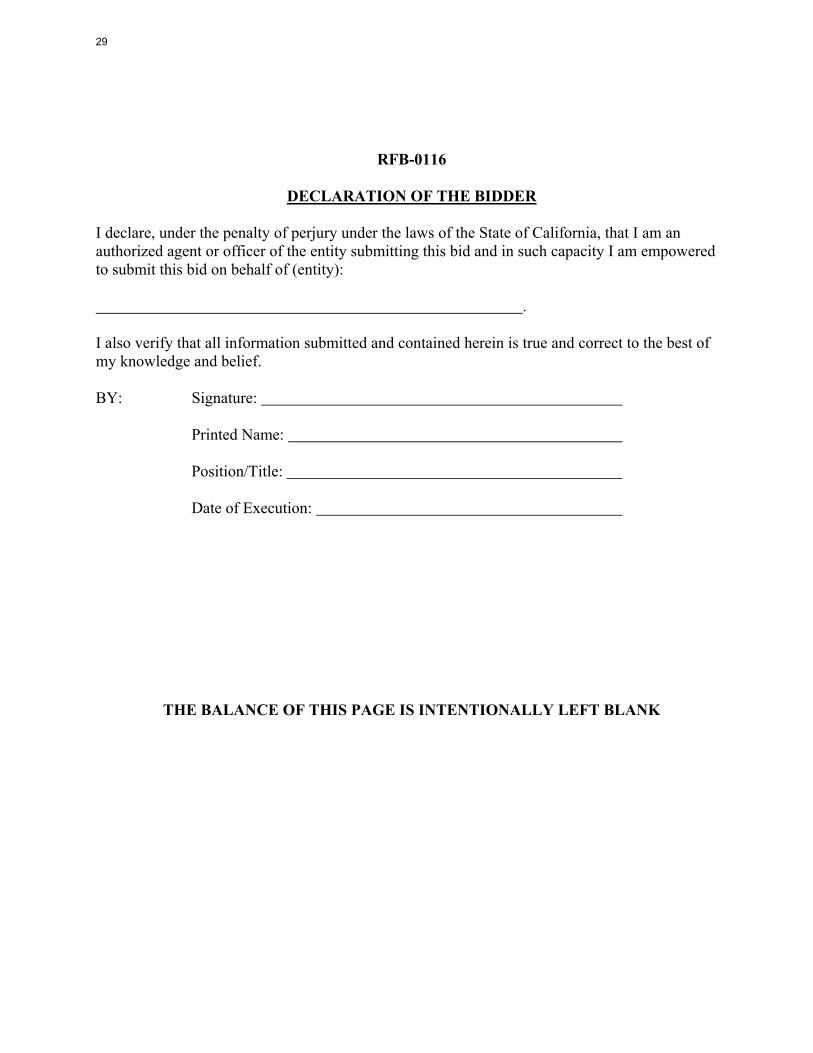
RFB-0116
DECLARATION OF THE BIDDER I declare, under the penalty of perjury under the laws of the State of California, that I am an authorized agent or officer of the entity submitting this bid and in such capacity I am empowered to submit this bid on behalf of (entity): . I also verify that all information submitted and contained herein is true and correct to the best of my knowledge and belief. BY: Signature: Printed Name: Position/Title: Date of Execution:
THE BALANCE OF THIS PAGE IS INTENTIONALLY LEFT BLANK
29

RFB-0116
EXTENSION OF CONTRACT TO OTHER PUBLIC AGENCIES
The prices, terms and conditions of this bid may be extended to other governmental agencies at the mutual agreement of both the City and the bidder. All requirements of the specifications, purchase orders, invoices, and payments with other agencies would be directly with the successful bidder. The City of Inglewood does not warrant any additional use of the contract by such agencies. The bidder’s response as requested below will no way affect the City of Inglewood’s consideration of this quote. Please indicate if this quote will be extended to other public agencies, and the length of time it will remain in effect from the opening date of this quote. Yes: No: Length of Time: Days /Months
THE BALANCE OF THIS PAGE IS INTENTIONALLY LEFT BLANK
30

RFB-0116
NON-COLLUSION DECLARATION
The undersigned hereby declares and says: That he has not, either directly or indirectly, entered into any agreement, participated in any collusion, or otherwise taken any action in restraint of free competitive bid offered in connection with the contract described below. (Full description of contract): I declare under penalty of perjury that the foregoing is true and correct to the best of my knowledge. Executed at , California, on (Month & Date) , 20 . Signature of Officer or Authorized Agent
31

NO BID FORM TO ALL BIDDERS: IF YOU DO NOT INTEND TO SUBMIT A BID FOR THIS PROJECT, PLEASE INDICATE BELOW AND
RETURN THIS FORM TO THE PURCHASING DIVISION OF THE CITY OF INGLEWOOD.
THE FIRM CANNOT SUPPLY THE SERVICES AS SPECIFIED, PLEASE CHANGE THE
CLASSIFICATION OF OUR FIRM TO THE FOLLOWING:
THE FIRM BELOW CANNOT SUBMIT A BID AT THIS TIME BECAUSE OF THE FOLLOWING:
.
THE FIRM BELOW IS NOT INTERESTED IN BEING ON THE CITY OF INGLEWOOD BIDDER LIST,
PLEASE REMOVE OUR NAME.
RFB Number: Name of Firm:
Address: Phone: Name of Individual: Signature: Date:
32

SCOPE OF WORK
DESIGN INSTRUCTIONS (Pages 34-41) STRUCTUAL STEEL FRAMING SPECIFICATIONS Section 051200 (Pages 42-46) CAST-IN-PLACE CONCRETE Section 033000 (Pages 47-59) DESIGN DEVELOPMENT DRAWINGS ( Pages 60-71)
NOTE: THAT THE FINAL PLANS MIGHT CHANGE ONCE THEY GO THROUGH THE BUILDING SAFETY PLAN CHECK PROCESS
AND ARE READY FOR BUILDING PERMIT ISSUANCE
33

CITY OF INGLEWOOD INGLEWOOD, CA WINDOW CLEANING EQUIPMENT 08.13.19 11 24 23-1
SECTION 11 24 23
WINDOW CLEANING EQUIPMENT EXTERIOR BUILDING MAINTENANCE (EBM) EQUIPMENT
FAÇADE ACCESS EQUIPMENT
PART 1 – GENERAL 1.1 SUMMARY
A. These performance specifications shall be read in conjunction with the Façade Access design drawings that are part of the construction documentation for this trade package, specifically sheets with “FA” prefix. Corresponding drawings were issue on 07.03.19 as Revision 5, 100% Design Development.
B. Provide all design, engineering, materials, manufacturing and installation labor required to deliver a complete Building Maintenance Unit (BMU) for EBM and Façade Access design necessary to provide access to all façade elements outlined on the Façade Access drawings. This project will result in an overall system complete with the following equipment, professional documentation and related work:
1. LEVEL ROOF
a. FIXED EQUIPMENT
1. One (1) - Building Maintenance Unit (BMU) 2. Two (2) – BMU Tracks
2. DOCUMENTATION
a. Original Equipment Manufacturer (OEM) Operations and Maintenance (O&M)
Manuals b. Demonstration of equipment
1.2 WORK EXCLUDED
A. The following are regulatory and operational project requirements not included in this section:
1. Guardrail systems. 2. Fixed ladders and other related access equipment. 3. Electronic two-way communication devices. 4. Electrical power receptacles and wiring as identified on drawings. 5. Water supply hose bibs as identified on drawings. 6. Waterproofing, flashings, etc. 7. Reinforcing of the building structure. 8. Operating Procedures Outline Sheet (OPOS).
1.3 RELATED SECTIONS
A. Division 1 General Requirements B. Division 3 Concrete C. Division 5 Metals
1.4 REGULATORY COMPLIANCE
A. All design, engineering, materials, equipment, system performance, inspection and testing, use
and written work product to comply with and be performed in compliance with the following applicable regulatory codes and standards. Special consideration shall be given to procuring the
34
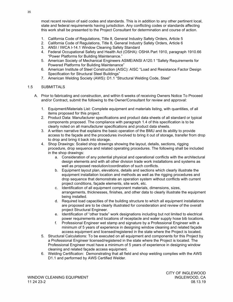
CITY OF INGLEWOOD WINDOW CLEANING EQUIPMENT INGLEWOOD, CA 11 24 23-2 08.13.19
most recent revision of said codes and standards. This is in addition to any other pertinent local, state and federal requirements having jurisdiction. Any conflicting codes or standards affecting this work shall be presented to the Project Consultant for determination and course of action. 1. California Code of Regulations, Title 8, General Industry Safety Orders, Article 5 2. California Code of Regulations, Title 8, General Industry Safety Orders, Article 6 3. ANSI / IWCA I-14.1 Window Cleaning Safety Standard 4. Federal Occupational Safety and Health Act (OSHA): OSHA Part 1910, paragraph 1910.66
“Power Platforms for Building Maintenance.” 5. American Society of Mechanical Engineers ASME/ANSI A120.1 “Safety Requirements for
Powered Platforms for Building Maintenance” 6. American Institute of Steel Construction (AISC): AISC “Load and Resistance Factor Design
Specification for Structural Steel Buildings” 7. American Welding Society (AWS): D1.1 “Structural Welding Code, Steel”
1.5 SUBMITTALS
A. Prior to fabricating and construction, and within 6 weeks of receiving Owners Notice To Proceed
and/or Contract, submit the following to the Owner/Consultant for review and approval: 1. Equipment/Materials List: Complete equipment and materials listing, with quantities, of all
items proposed for this project. 2. Product Data: Manufacturer specifications and product data sheets of all standard or typical
components proposed. The compliance with paragraph 1.4 of this specification is to be clearly noted on all manufacturer specifications and product data sheets.
3. A written narrative that explains the basic operation of the BMU and its ability to provide access to the façade and the procedures involved to bring it out of storage, transfer from drop to drop and bring it back into storage.
4. Shop Drawings: Scaled shop drawings showing the layout, details, sections, rigging procedure, drop sequence and related operating procedures. The following shall be included in the shop drawings:
a. Consideration of any potential physical and operational conflicts with the architectural design elements and with all other division trade work installations and systems as well as proposed resolution/coordination of such conflicts.
b. Equipment layout plan, elevations, details and sections which clearly illustrate the equipment installation location and methods as well as the rigging procedures and drop sequence that demonstrate an operation system without conflicts with current project conditions, façade elements, site work, etc.
c. Identification of all equipment component materials, dimensions, sizes, arrangements, thicknesses, finishes, and other data to clearly illustrate the equipment being installed.
d. Required load capacities of the building structure to which all equipment installations are proposed are to be clearly illustrated for consideration and review of the overall project Structural Engineer.
e. Identification of “other trade” work designations including but not limited to electrical power requirements and locations of receptacle and water supply hose bib locations.
f. Professional Engineer wet stamp and signature by a Professional Engineer with a minimum of 5 years of experience in designing window cleaning and related façade access equipment and licensed/registered in the state where the Project is located.
5. Structural Calculations: To be executed on all equipment and components for this Project by a Professional Engineer licensed/registered in the state where the Project is located. The Professional Engineer must have a minimum of 5 years of experience in designing window cleaning and related façade access equipment.
6. Welding Certification: Demonstrating that all field and shop welding complies with the AWS D1.1 and performed by AWS Certified Welder.
35

CITY OF INGLEWOOD INGLEWOOD, CA WINDOW CLEANING EQUIPMENT 08.13.19 11 24 23-3
B. After fabrication and construction, submit the following to the Owner/Consultant for review and approval: 1. Test results from all Inspections and Tests conducted per paragraph 3.3. 2. Equipment Warranty: Three (3) copies 3. Operation and Maintenance Manual: Three (3) copies, labeled, bound and neatly illustrated
documenting the operation and maintenance of the “specific” equipment installed on this Project. Minimum manual requirements are as follows:
a. Table of Contents b. Manufacturer c. Equipment Inventory complete with location and serial numbers. d. Warnings and Notices. e. Illustration of Labels and Notices affixed to permanent and portable equipment. f. Inspection Check List (Periodic and Maintenance Inspections). g. Inspection Log (Periodic, Maintenance, Daily). h. Maintenance procedures. i. Operating procedures. j. Troubleshooting. k. Rescue Plan. l. Rigging Access Plan. m. Warranty in triplicate.
1.6 QUALITY ASSURANCE
A. California Projects: All equipment is to be manufactured and installed by a manufacturer or
contractor possessing a current and valid Scaffold Inspection and Testing Agency (SIT) designation by the California Department of Industrial Relations, Division of Occupational Safety and Health.
B. Engineer Qualifications: Registered Professional Engineer licensed to practice in the jurisdiction where the Project is located possessing a minimum of 5 years experience in designing building maintenance, façade access and related fall protection equipment. Per CCR T8 GISO 3294(a)(1) and 3295(a)(1) the engineer shall be “experienced in such design”
C. Manufacturer Qualifications: Manufacturer’s primary trade is the design and manufacturing of window cleaning and related façade access equipment and has been actively engaged in this business for not less than 10 years.
D. Contractor/Installer Qualifications: Installer is required to be employed by manufacturer or provide written approval from manufacturer to install its products.
E. Welder Qualifications: AWS certified within the last 12 months for each type of weld required. F. Regulatory Compliance: Refer to paragraph 1.4
1.7 DELIVERY, STORAGE AND HANDLING
A. Deliver all equipment and material to the project properly packaged according to the
manufacturer’s packaging requirements in sizes as large as practical. B. Store materials under cover in a dry and clean location off the ground. C. Damaged or faulty equipment or materials are to be removed from the project and replaced with
acceptable equipment or materials.
1.8 WARRANTY
A. Provide Manufacturer’s Warranty for a period of three (3) year(s) to cover the following: 1. Material defects. 2. Workmanship. 3. Installation (self performed) 4. Installation (by other trades) 5. Certification clause of adherence to paragraph 1.4 (Regulatory Compliance)
36

CITY OF INGLEWOOD WINDOW CLEANING EQUIPMENT INGLEWOOD, CA 11 24 23-4 08.13.19
B. Warranty to be submitted on original certificated document. Three (3) originals to contain wet
signatures by the authorizing party.
C. Provide warranty for wire rope for the period of time set by the wire rope Manufacturer.
PART 2 - PRODUCTS 2.1 CONTRACTORS / INSTALLERS
A. Contractor / Installer Qualifications:
1. California Projects: All equipment is to be installed by a manufacturer or contractor
possessing a current and valid Scaffold Inspection and Testing Agency (SIT) designation by the California Department of Industrial Relations, Division of Occupational Safety and Health.
2. Installer is required to be employed by manufacturer or provide written approval from manufacturer to install its products and have a minimum of 5 years experience in the installation of this and related equipment.
2.2 DESIGN REQUIREMENTS
A. The complete Building Maintenance Equipment system including individual components and overall functionality is to be designed by or under the direction of a Professional Engineer registered in the state where the project is located. Duties and responsibilities include verification that all components supplied comply with the applicable portions of paragraph 1.4 above.
B. In addition to compliance with the design requirements of the various regulatory standards cited in paragraph 1.4, special attention shall be given to the following: 1. All loads transferred to the building structure by the equipment in this section are to be clearly
called out on the drawings and calculations and submitted for review to the overall Project Structural Engineer for review and consideration of any required additional reinforcing of the structure.
2. A minimum safety factor of four (4) is to be designed into all equipment in this section. Exceptions to this are the following:
a. Suspension Wire Rope: the minimum safety factor shall be ten (10). b. Tie-Back Anchors: 5000 pound anchorage and assembly strength for loads applied in
any direction without any permanent deflection. c. Horizontal / Catenary Lines: the minimum safety factor shall be two (2).
3. All parapets upon which working lines and safety lines are resting to be designed with consideration of the static and dynamic loading of the CDA system and potential shock loading of a fall arrest incident.
2.3 COMPONENTS
A. Building Maintenance Unit (BMU): Furnish a track mounted BMU for the application required that serves each elevation and that is designed, engineered and fabricated to the standards and regulations cited in this specification including but not limited to the following:
1. Prevailing Climatic Conditions for Project Location
a. The BMU shall be designed to withstand and operate normally under the winter months prevailing climatic conditions of the Project location including but not limited to: 1. All electric motors, gearboxes and other electrical enclosures shall be equipped
as follows: a. Conform to International Electrotechnical Commission (IEC), Ingress
Protection (IP) Rating of IP66 or equivalent.
37

CITY OF INGLEWOOD INGLEWOOD, CA WINDOW CLEANING EQUIPMENT 08.13.19 11 24 23-5
2. The hoist/drum and hydraulic motor enclosure shall be weather tight and prevent the intrusion of wind driven rain and snow.
3. All enclosure boxes shall have heating elements. 4. All Hydraulic Systems including hydraulic pumps, valves, fittings, lines, pistons,
rams, actuators shall be equipped as follows: a. Hydraulic pumps shall have a start rating allowing cold starts 0 degrees
Fahrenheit when equipped with compatible hydraulic oil. b. Hydraulic lines shall be equipped with heat trace elements, allowing the
intended pressurization and flow of hydraulic oil by the hydraulic pump. c. BMU operation under winter month prevailing climatic conditions for the
Project located in Inglewood, CA shall be considered operations during temperatures of 18 degrees Fahrenheit.
d. Any required cold start maintenance or procedures that may be required in order to operate the BMU under the prevailing climatic conditions shall be limited to those that are easily and readily performed by the BMU operator and shall not require the need for a specialized service technician.
2. Vibration, Harmonic Noise 1. Hydraulic Shock and Hammer: Any hydraulic system shall be design with
consideration to eliminate or minimize adverse hydraulic shock. This shall be accomplished hydraulic fluid velocity control by or a combination of; 1) hydraulic column diameter; 2) choking valve switching time; 3) Metering in or Metering Out flow control; or 4) any means necessary to prevent adverse noise and vibration transmission through the building.
3. The electrically powered BMU shall be designed and installed by the manufacturer/contractor, so as to safely maintain the suspended work platform (cradle) in working positions over the side of the building.
4. The BMU controls and safety system shall include safety interlocks as required. 5. The counter-weighted powered BMU system shall provide the following functions:
a. Provide transportation for the suspended cradle to any work position selected by the operators, as detailed, in order to provide coverage to all exterior areas of building designated to be maintained.
b. Provide suspension of the cradle as required and provide a safe and efficient means during raising and lowering the cradle during operational moves (as required).
c. The vertical travel of the cradle shall be by means of hoisting unit(s) located at the roof in the BMU carriage.
d. Provide an electrically powered system, controlled through a pendant or fixed station, which include the following powered features: 1. Slewing of the knuckle boom 2. Telescoping of the Boom 3. Slewing of the Spreader Bar. 4. Elevating Mast
e. Primary control of the BMU carriage should be at the platform (cradle). Secondary controls shall be provided at the carriage, with pendant (if required).
f. The control system between the platform (cradle) and the boom shall be hard wired. g. Access to, or function of, the operating controls shall be by controlled access (key or
code) to prevent unauthorized operation. h. The BMU and cradle shall be provided with electrical and mechanical interlocks to
prevent damage to the building façade elements including the curtain wall, parapet and any other adjacent building features.
i. Electrical and mechanical interlocks to prevent slewing of the BMU boom when the cradle is suspended below the parapet at a working position shall be provided.
j. The BMU shall travel on steel tracks. k. Finish: The total system shall be hot-dipped galvanized and then painted with (2)
coats of machinery enamel; color shall be selected by the Architect or Owner. l. The BMU shall include any and all features, as required, to allow storage in the
designated area and clearance behind the architectural features as shown on the FA drawings.
38

CITY OF INGLEWOOD WINDOW CLEANING EQUIPMENT INGLEWOOD, CA 11 24 23-6 08.13.19
m. The manufacturer/contractor shall complete the installation according to all applicable codes and standards having jurisdiction including those portions of City, State and Federal regulations.
n. Maintenance and Inspection Access: The BMU shall be designed to provide ready and free access to all components that require routine inspection and maintenance. Those include gear motors, hydraulic systems, racks and pinions, hang points, lugs, mechanical and electrical enclosures among others. Such access shall comply with applicable regulatory codes and consensus standards cited in this specification. In particular, maintenance access shall address fall protection and access requirements including the implementation of raised platforms, guardrails, ladders or stairs, etc.
6. The platform (cradle) shall be designed, furnished and installed by the manufacturer/contractor, so as to safely provide access to the building exterior as well as fulfill the following requirements:
a. Structural members shall be of aluminum alloy or steel. Materials shall be corrosion resistant or protected against corrosion according to best commercial practice. All fasteners and miscellaneous hardware shall be stainless steel or hot dipped galvanized. Zinc plated materials will be rejected.
b. The cradle shall be provided with attachment points of adequate strength for securing worker safety lanyards and harnesses and additional points for the restraint of miscellaneous hand tools.
c. Multiple non-marking, non-scuffing roller assemblies, adjustable; horizontally and extendable shall be provided. The quantity features and size of roller assemblies require approval of the Consultant.
d. Capacity: 500 pounds live load minimum. e. The safe working load in pounds and the number of personnel allowed to occupy the
cradle when suspended should be clearly indicated on the cradle. Such indications being readily visible to personnel when gaining access to the cradle.
f. Control station(s) with approved English Language controls and indicators shall be provided on the cradle.
g. Emergency “STOP” (red button) must be provided at the control station(s) which is pressed in case of emergency, shall shut off power, apply primary brakes, and stop all movement.
h. Lower obstruction limits that halt the downward travel of the cradle when an obstruction or overhang is encountered.
i. Slack cable switches that will stop the hoist if any slack develops in any suspension rope during operation.
7. The hoist should be roof mounted and fulfill the following requirements: a. Be provided with over speed locks. b. Have a primary, mechanical brake acting directly on the lifting motor shaft, which
would be automatically applied if either of the following conditions occurs: 1. Sudden downward acceleration. 2. Excess downward speed.
8. Automatic safety devices required: a. Overload sensor switch. b. Under load sensor switch. c. Second limit switch in main circuit that will directly interrupt the power supply to the
motor, independent of the working control circuit, if the limit switch in the control system fails.
d. Limit switch that stops the ascent of the cradle when an obstruction or overhang is encountered.
e. Limit switch that stops the descent of the cradle when an obstruction or overhang in encountered.
f. Provisions must be provided to lower the cradle manually, at a controlled rate, in case of an emergency after communication with cradle operators.
9. Factory Acceptance a. Prior to delivery of the completed BMU, a Factory Acceptance event shall take place
with the consultant present. The manufacturer shall submit a Factory Acceptance
39

CITY OF INGLEWOOD INGLEWOOD, CA WINDOW CLEANING EQUIPMENT 08.13.19 11 24 23-7
Test (FAT) checklist that lists all of the observations, functions and tests to be conducted. At minimum the FAT shall include: 1. Verification of:
a. BMU mass b. Wheel loads (storage and working for rated load and 2 x rated load)
2. Among other multiple customary functional and dimensional testing and verification.
PART 3 – EXECUTION 3.1 EXAMINATION
A. All affected and affecting work areas, installations, etc. shall be examined to ensure physical
conditions and other related conditions are adequate for the subsequent installation.
B. Consideration of any potential physical and operational conflicts with the architectural design elements and with all other division trade work installations and systems shall be made as well as proposed resolution/coordination of such conflicts be developed.
3.2 INSTALLATION
A. All installations shall be performed in accordance with all original design drawings, shop drawings, approved submittals, manufacturer specifications and applicable regulatory governmental compliance.
B. Coordination with other division trade work installations is mandatory.
3.3 FIELD QUALITY CONTROL
A. Tests and Inspections: The following inspections and tests shall be conducted on components and installed equipment to ensure compliance with this specification and full operational functionality of the overall system. Any material, equipment functionality and operational deficiencies noted as a result of these inspections and tests shall be corrected and re-inspected/tested to verify compliance with this specification. 1. All inspection criteria, operational testing procedures and load test prescriptions to be
obtained by the original equipment manufacturer, in writing, prior the conduction any of the following tests.
2. Tie-Back Anchors: Each loop to be tested in a manner as prescribed by the manufacturer to a load no less than 50% of its design load capacity but no more than 2500 pounds.
3. Suspension Equipment (Davits, Sockets, Pedestals, Outriggers, Carriages, etc.): Full live load and operational tests under the maximum live loading conditions over the complete range of the overall system. When Suspension Equipment also incorporate independent tieback or fall arrest anchorage, the assembly shall be load tested as listed in the “Tie Back Anchors” item of this section so that the load is transferred to the primary building structure.
4. Suspended Equipment: Verify the dead (self) weight of the platform. 5. Building Maintenance Units (BMU) and Carriages: In addition to the other applicable tests
included in this section, the following tests shall be conducted: a. Mass: Verify dead weight of the completely assembled BMU or Carriage laden with
and without the applicable rated loads of the work platform/cradle and any auxiliary hoisting equipment.
b. Reactions: Verify wheel loads for each working and storage configuration. c. Work platform / cradle: Verify dead weight.
6. The OEM design engineer is responsible for issuing a Certificate of Regulation Compliance as per the paragraph 3.4 of this specification.
7. Catenary Lines / Horizontal Life Lines: Each wire rope line shall be tested when fabricated in the shop or in the field to a load no less than 50% of its design load capacity.
40

CITY OF INGLEWOOD WINDOW CLEANING EQUIPMENT INGLEWOOD, CA 11 24 23-8 08.13.19
B. Structural Tests and Special Inspections: When any work involves activity regulated by the
Uniform Building Code Chapter 17, or any other authority having jurisdiction, any structural tests or special inspections required shall be coordinated and performed as per the requirements of the Uniform Building Code or any other authority having jurisdiction over such work.
C. All test results shall be recorded and submitted according to paragraph 1.5.
3.4 CERTIFICATION
A. Provide a written Certificate of Compliance for all components and equipment installed under this specification certifying the following:
1. All components and equipment have been manufactured and installed according to all Project
regulations and applicable regulatory jurisdiction. 2. The components and equipment has been inspected and tested according to the provisions
in paragraph 3.3 and have successfully passed. 3. The system is operational and ready for owner turnover. 4. Certificate of Compliance to be dated and signed by a qualified representative of the
contractor/manufacturer.
3.5 DEMONSTRATION
A. Only once the complete system has been installed, inspected and tested, and a Certificate of Compliance has been issued, a demonstration of said equipment is to be arranged with the General Contractor and Owner at a time that is mutually agreeable. The following conditions shall apply to the demonstration of the equipment:
1. The demonstration event shall not be used to satisfy the requirements of part 3.3 of this
specification. 2. The demonstration shall include, but is not limited to, the following:
a. One functional demonstration of each type of equipment at every unique building/rigging condition where that type of equipment occurs.
B. Instruction, as needed, shall be provided to Owner representatives during the demonstration.
END OF SECTION 11 24 23
41

Copyright 2010 AIA MasterSpec Outline 02/10
STRUCTURAL STEEL FRAMING 051200 - 1
SECTION 051200 - STRUCTURAL STEEL FRAMING
PART 1 - GENERAL
1.1 SUMMARY
A. Structural steel as classified by AISC 303.
B. Grout.
1.2 PERFORMANCE REQUIREMENTS
A. Connections: 1. Provide connections as shown or noted on Drawings. Design of connections not shown
or noted shall be provided by Structural Engineer-of-Record upon request.
1.3 QUALITY ASSURANCE
A. Fabricator Qualifications: AISC-Certified Plant, Category STD.
B. Installer Qualifications: AISC-Certified Erector, Category CSE.
C. Quality Standards: AISC 303 and AISC 360.
1.4 ACTION SUBMITTALS
A. Shop and Erection Drawings: Show location, fabrication, and assembly of structural-steel components.
1. Location of each piece or detail within the structure. 2. Include details of cuts, connections, splices, camber, holes, and other pertinent data. 3. Include embedment piece and setting drawings. 4. Indicate welds by standard AWS symbols, distinguishing between shop and field welds,
and show size, length, and type of each weld. Show backing bars that are to be removed and supplemental fillet welds where backing bars are to remain.
5. Indicate type, size, and length of bolts, distinguishing between shop and field bolts. Identify pretensioned and slip-critical high-strength bolted connections.
6. Drawings submitted in multiple packages shall contain individual submittals complete with all applicable erection drawings, details, and piece drawings.
7. Reproduction of Contract Documents is not permitted.
1.5 INFORMATIONAL SUBMITTALS
A. Qualification Data: For qualified Installer and fabricator.
42
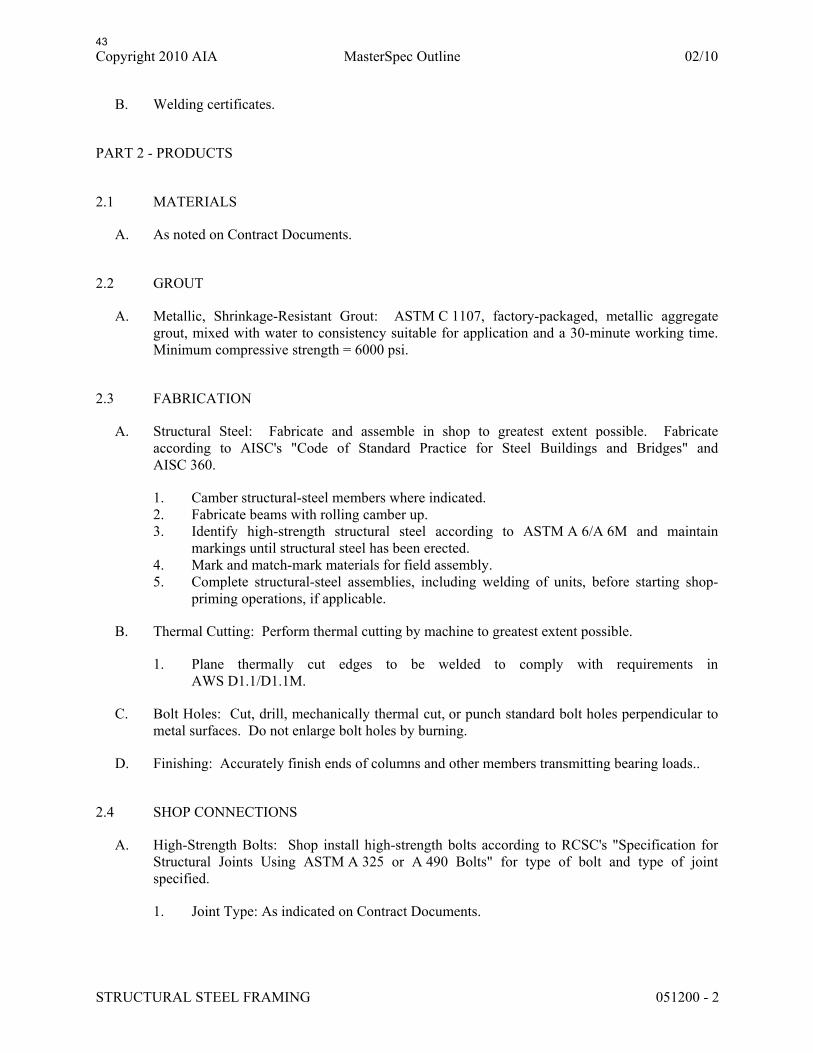
Copyright 2010 AIA MasterSpec Outline 02/10
STRUCTURAL STEEL FRAMING 051200 - 2
B. Welding certificates.
PART 2 - PRODUCTS
2.1 MATERIALS
A. As noted on Contract Documents.
2.2 GROUT
A. Metallic, Shrinkage-Resistant Grout: ASTM C 1107, factory-packaged, metallic aggregate grout, mixed with water to consistency suitable for application and a 30-minute working time. Minimum compressive strength = 6000 psi.
2.3 FABRICATION
A. Structural Steel: Fabricate and assemble in shop to greatest extent possible. Fabricate according to AISC's "Code of Standard Practice for Steel Buildings and Bridges" and AISC 360.
1. Camber structural-steel members where indicated. 2. Fabricate beams with rolling camber up. 3. Identify high-strength structural steel according to ASTM A 6/A 6M and maintain
markings until structural steel has been erected. 4. Mark and match-mark materials for field assembly. 5. Complete structural-steel assemblies, including welding of units, before starting shop-
priming operations, if applicable.
B. Thermal Cutting: Perform thermal cutting by machine to greatest extent possible.
1. Plane thermally cut edges to be welded to comply with requirements in AWS D1.1/D1.1M.
C. Bolt Holes: Cut, drill, mechanically thermal cut, or punch standard bolt holes perpendicular to metal surfaces. Do not enlarge bolt holes by burning.
D. Finishing: Accurately finish ends of columns and other members transmitting bearing loads..
2.4 SHOP CONNECTIONS
A. High-Strength Bolts: Shop install high-strength bolts according to RCSC's "Specification for Structural Joints Using ASTM A 325 or A 490 Bolts" for type of bolt and type of joint specified.
1. Joint Type: As indicated on Contract Documents.
43

Copyright 2010 AIA MasterSpec Outline 02/10
STRUCTURAL STEEL FRAMING 051200 - 3
B. Weld Connections: Comply with AWS D1.1/D1.1M for tolerances, appearances, welding procedure specifications, weld quality, and methods used in correcting welding work.
2.5 GALVANIZING
A. Hot-Dip Galvanized Finish: Apply zinc coating by the hot-dip process to structural steel according to ASTM A 123/A 123M.
2.6 DELIVERY, STORAGE, AND HANDLING
A. Store materials to permit easy access for inspection and identification. Keep steel members off ground and spaced by using pallets, dunnage, or other supports and spacers. Protect steel members and packaged materials from corrosion and deterioration.
1. Do not store materials on structure in a manner that might cause distortion, damage, or overload to members or supporting structures. Repair or replace damaged materials or structures as directed.
B. Store fasteners in a protected place in sealed containers with manufacturer's labels intact.
1. Fasteners may be repackaged provided Owner's testing and inspecting agency observes repackaging and seals containers.
2. Clean and relubricate bolts and nuts that become dry or rusty before use. 3. Comply with manufacturers' written recommendations for cleaning and lubricating
ASTM F 1852 fasteners and for retesting fasteners after lubrication.
2.7 SOURCE QUALITY CONTROL
A. Testing Agency: Owner engaged as indicated on Contract Documents.
PART 3 - EXECUTION
3.1 EXAMINATION
A. Verify, with steel Erector present, elevations of concrete, bearing plates, and other embedments for compliance with requirements.
1. Prepare a certified survey of bearing surfaces, anchor rods, bearing plates, and other embedments showing dimensions, locations, angles, and elevations.
B. Proceed with installation only after unsatisfactory conditions have been corrected.
3.2 PREPARATION
A. Provide temporary shores, guys, braces, and other supports during erection to keep structural steel secure, plumb, and in alignment against temporary construction loads and loads equal in
44

Copyright 2010 AIA MasterSpec Outline 02/10
STRUCTURAL STEEL FRAMING 051200 - 4
intensity to design loads. Remove temporary supports when permanent structural steel, connections, and bracing are in place unless otherwise indicated.
1. Coordinate installation of non-structural steel items that load the temporarily supported steel frame such that temporary supports are adequate to resist all imposed loads.
3.3 ERECTION
A. Set structural steel accurately in locations and to elevations indicated and according to AISC 303 and AISC 360.
B. Bearing Plates: Clean concrete-bearing surfaces of bond-reducing materials and clean bottom surface of plates.
1. Set plates for structural members on wedges, shims, or setting nuts as required. 2. Clean and moisten surfaces to receive grout. Immediately remove any remaining free
water. Promptly pack grout solidly between bearing surfaces and plates so no voids remain. Neatly finish exposed surfaces; protect grout and allow to cure. Comply with manufacturer's written installation instructions for shrinkage-resistant grouts.
C. Maintain erection tolerances of structural steel within AISC's "Code of Standard Practice for Steel Buildings and Bridges."
D. Align and adjust various members that form part of complete frame or structure before permanently fastening. Before assembly, clean bearing surfaces and other surfaces that will be in permanent contact with members. Perform necessary adjustments to compensate for discrepancies in elevations and alignment.
1. Level and plumb individual members of structure. 2. Make allowances for difference between temperature at time of erection and mean
temperature of 70° F when structure is completed and in service.
E. Do not enlarge unfair holes in members by burning or using drift pins. Ream holes that must be enlarged to admit bolts.
3.4 FIELD CONNECTIONS
A. High-Strength Bolts: Install high-strength bolts according to RCSC's "Specification for Structural Joints Using ASTM A 325 or A 490 Bolts" for type of bolt and type of joint specified.
1. Joint Type: As indicated on Contract Documents.
B. Weld Connections: Comply with AWS D1.1/D1.1M for tolerances, appearances, welding procedure specifications, weld quality, and methods used in correcting welding work.
1. Comply with AISC 303 and AISC 360 for bearing, alignment, adequacy of temporary connections, and removal of paint on surfaces adjacent to field welds.
2. Remove backing bars or runoff tabs where indicated on Drawings, back gouge, and grind steel smooth.
45

Copyright 2010 AIA MasterSpec Outline 02/10
STRUCTURAL STEEL FRAMING 051200 - 5
3.5 FIELD QUALITY CONTROL
A. Testing and Inspection: As indicated on Drawings.
3.6 REPAIRS AND PROTECTION
A. Galvanized Surfaces: Clean areas where galvanizing is damaged or missing and repair galvanizing to comply with ASTM A 780.
END OF SECTION 051200
46

Copyright 2014 AIA MasterSpec Premium 06/14
CAST-IN-PLACE CONCRETE 033000 - 1
SECTION 033000 - CAST-IN-PLACE CONCRETE
PART 1 - GENERAL
1.1 RELATED DOCUMENTS
A. Drawings and general provisions of the Contract, including General and Supplementary Conditions and Division 01 Specification Sections, apply to this Section.
1.2 SUMMARY
A. Section includes cast-in-place concrete, including formwork, reinforcement, concrete materials, mixture design, placement procedures, and finishes.
1.3 DEFINITIONS
A. Cementitious Materials: Portland cement alone or in combination with one or more of the following: blended hydraulic cement, fly ash, slag cement, other pozzolans, and silica fume; materials subject to compliance with requirements.
B. W/C Ratio: The ratio by weight of water to cementitious materials.
1.4 ACTION SUBMITTALS
A. Product Data: For each type of product.
B. Design Mixtures: For each concrete mixture. Submit alternate design mixtures when characteristics of materials, Project conditions, weather, test results, or other circumstances warrant adjustments.
1. Indicate amounts of mixing water to be withheld for later addition at Project site.
C. Steel Reinforcement Shop Drawings: Placing Drawings that detail fabrication, bending, and placement. Include bar sizes, lengths, material, grade, bar schedules, stirrup spacing, bent bar diagrams, bar arrangement, splices and laps, mechanical connections, tie spacing, hoop spacing, and supports for concrete reinforcement.
1.5 INFORMATIONAL SUBMITTALS
A. Material Certificates: For each of the following, signed by manufacturers:
1. Cementitious materials. 2. Admixtures. 3. Form materials and form-release agents. 4. Steel reinforcement and accessories.
47
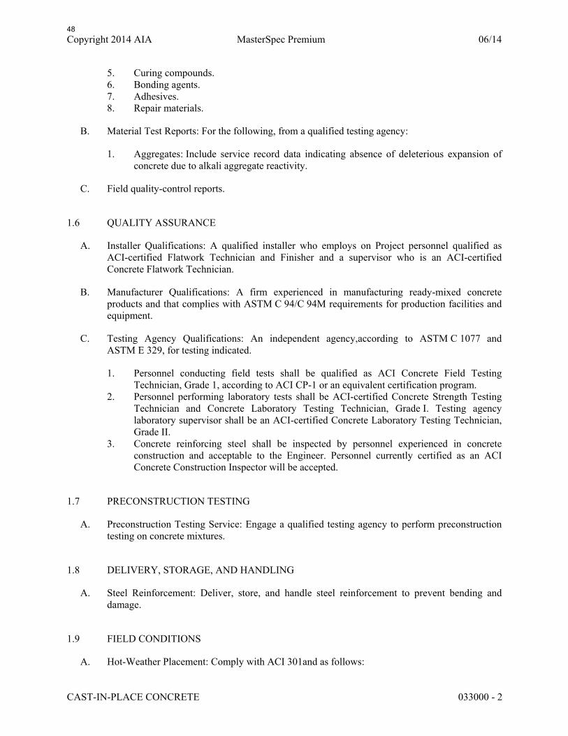
Copyright 2014 AIA MasterSpec Premium 06/14
CAST-IN-PLACE CONCRETE 033000 - 2
5. Curing compounds. 6. Bonding agents. 7. Adhesives. 8. Repair materials.
B. Material Test Reports: For the following, from a qualified testing agency:
1. Aggregates: Include service record data indicating absence of deleterious expansion of concrete due to alkali aggregate reactivity.
C. Field quality-control reports.
1.6 QUALITY ASSURANCE
A. Installer Qualifications: A qualified installer who employs on Project personnel qualified as ACI-certified Flatwork Technician and Finisher and a supervisor who is an ACI-certified Concrete Flatwork Technician.
B. Manufacturer Qualifications: A firm experienced in manufacturing ready-mixed concrete products and that complies with ASTM C 94/C 94M requirements for production facilities and equipment.
C. Testing Agency Qualifications: An independent agency,according to ASTM C 1077 and ASTM E 329, for testing indicated.
1. Personnel conducting field tests shall be qualified as ACI Concrete Field Testing Technician, Grade 1, according to ACI CP-1 or an equivalent certification program.
2. Personnel performing laboratory tests shall be ACI-certified Concrete Strength Testing Technician and Concrete Laboratory Testing Technician, Grade I. Testing agency laboratory supervisor shall be an ACI-certified Concrete Laboratory Testing Technician, Grade II.
3. Concrete reinforcing steel shall be inspected by personnel experienced in concrete construction and acceptable to the Engineer. Personnel currently certified as an ACI Concrete Construction Inspector will be accepted.
1.7 PRECONSTRUCTION TESTING
A. Preconstruction Testing Service: Engage a qualified testing agency to perform preconstruction testing on concrete mixtures.
1.8 DELIVERY, STORAGE, AND HANDLING
A. Steel Reinforcement: Deliver, store, and handle steel reinforcement to prevent bending and damage.
1.9 FIELD CONDITIONS
A. Hot-Weather Placement: Comply with ACI 301and as follows:
48

Copyright 2014 AIA MasterSpec Premium 06/14
CAST-IN-PLACE CONCRETE 033000 - 3
1. Maintain concrete temperature below 90 deg Fat time of placement. Chilled mixing water or chopped ice may be used to control temperature, provided water equivalent of ice is calculated to total amount of mixing water. Using liquid nitrogen to cool concrete is Contractor's option.
2. Fog-spray forms and steel reinforcement just before placing concrete. Keep substrate uniformly moist without standing water or dry areas.
PART 2 - PRODUCTS
2.1 CONCRETE, GENERAL
A. ACI Publications: Comply with the following unless modified by requirements in the Contract Documents:
1. ACI 301 2. ACI 117
2.2 FORM-FACING MATERIALS
A. Smooth-Formed Finished Concrete: Form-facing panels that provide continuous, true, and smooth concrete surfaces. Furnish in largest practicable sizes to minimize number of joints.
1. Plywood, metal, or other approved panel materials. 2. Exterior-grade plywood panels, suitable for concrete forms, complying with DOC PS 1,
and as follows:
a. High-density overlay, Class 1 or better. b. Medium-density overlay, Class 1 or better; mill-release agent treated and edge
sealed. c. Structural 1, B-B or better; mill oiled and edge sealed. d. B-B (Concrete Form), Class 1 or better; mill oiled and edge sealed.
B. Chamfer Strips: Wood, metal, PVC, or rubber strips, 3/4 by 3/4 inch, minimum.
C. Form-Release Agent: Commercially formulated form-release agent that does not bond with, stain, or adversely affect concrete surfaces and does not impair subsequent treatments of concrete surfaces.
1. Formulate form-release agent with rust inhibitor for steel form-facing materials.
D. Form Ties: Factory-fabricated, removable or snap-off glass-fiber-reinforced plastic or metal form ties designed to resist lateral pressure of fresh concrete on forms and to prevent spalling of concrete on removal.
1. Furnish units that leave no corrodible metal closer than 1 inch to the plane of exposed concrete surface.
2. Furnish ties that, when removed, leave holes no larger than 1 inchin diameter in concrete surface.
49

Copyright 2014 AIA MasterSpec Premium 06/14
CAST-IN-PLACE CONCRETE 033000 - 4
3. Furnish ties with integral water-barrier plates to walls indicated to receive dampproofing or waterproofing.
2.3 STEEL REINFORCEMENT
A. Reinforcing Bars: ASTM A 615/A 615M, Grade 60deformed.
2.4 REINFORCEMENT ACCESSORIES
A. Bar Supports: Bolsters, chairs, spacers, and other devices for spacing, supporting, and fastening reinforcing bars and welded-wire reinforcement in place. Manufacture bar supports from steel wire, plastic, or precast concrete according to CRSI's "Manual of Standard Practice," of greater compressive strength than concrete and as follows:
1. For concrete surfaces exposed to view, where legs of wire bar supports contact forms, use CRSI Class 1 plastic-protected steel wire or CRSI Class 2 stainless-steel bar supports.
2. For epoxy-coated reinforcement, use epoxy-coated or other dielectric-polymer-coated wire bar supports.
3. For zinc-coated reinforcement, use galvanized wire or dielectric-polymer-coated wire bar supports.
2.5 CONCRETE MATERIALS
A. Source Limitations: Obtain each type or class of cementitious material of the same brand from the same manufacturer's plant, obtain aggregate from single source, and obtain admixtures from single source from single manufacturer.
B. Cementitious Materials - Alternate cementitious materials, when proposed to control alkali-silica reactions and tested as part of a representative complete concrete mix in accordance with ASTM C1567, may be used subject to approval:
1. Portland Cement: ASTM C 150/C 150M, Type I/II, gray. 2. Fly Ash: ASTM C 618, Class F or C.
C. Normal-Weight Aggregates: ASTM C 33/C 33M, Class 3S coarse aggregate or better, graded. Provide aggregates from a single source.
1. Maximum Coarse-Aggregate Size: 3/4 inchnominal. 2. Fine Aggregate: Free of materials with deleterious reactivity to alkali in cement.
D. Chemical Admixtures: Certified by manufacturer to be compatible with other admixtures and that do not contribute water-soluble chloride ions exceeding those permitted in hardened concrete. Do not use calcium chloride or admixtures containing calcium chloride.
1. Water-Reducing Admixture: ASTM C 494/C 494M, Type A. 2. Retarding Admixture: ASTM C 494/C 494M, Type B. 3. Water-Reducing and Retarding Admixture: ASTM C 494/C 494M, Type D. 4. High-Range, Water-Reducing Admixture: ASTM C 494/C 494M, Type F. 5. High-Range, Water-Reducing and Retarding Admixture: ASTM C 494/C 494M, Type G.
50

Copyright 2014 AIA MasterSpec Premium 06/14
CAST-IN-PLACE CONCRETE 033000 - 5
6. Plasticizing and Retarding Admixture: ASTM C 1017/C 1017M, Type II.
E. Water: ASTM C 94/C 94M and potable.
2.6 CURING MATERIALS
A. Evaporation Retarder: Waterborne, monomolecular film forming, manufactured for application to fresh concrete.
B. Absorptive Cover: AASHTO M 182, Class 2, burlap cloth made from jute or kenaf, weighing approximately 9 oz./sq. yd. when dry.
C. Moisture-Retaining Cover: ASTM C 171, polyethylene film or white burlap-polyethylene sheet.
D. Water: Potable.
E. Clear, Solvent-Borne, Membrane-Forming Curing and Sealing Compound: ASTM C 1315, Type 1, Class A.
F. Clear, Waterborne, Membrane-Forming Curing and Sealing Compound: ASTM C 1315, Type 1, Class A.
2.7 RELATED MATERIALS
A. Expansion- and Isolation-Joint-Filler Strips: ASTM D 1751, asphalt-saturated cellulosic fiber
B. Bonding Agent: ASTM C 1059/C 1059M, Type II, nonredispersible, acrylic emulsion or styrene butadiene.
2.8 REPAIR MATERIALS
A. Repair Underlayment: Cement-based, polymer-modified, self-leveling product that can be applied in thicknesses from 1/8 inch and that can be feathered at edges to match adjacent floor elevations.
1. Cement Binder: ASTM C 150/C 150M, portland cement or hydraulic or blended hydraulic cement as defined in ASTM C 219.
2. Primer: Product of underlayment manufacturer recommended for substrate, conditions, and application.
3. Aggregate: Well-graded, washed gravel, 1/8 to 1/4 inch or coarse sand as recommended by underlayment manufacturer.
4. Compressive Strength: Not less than 4100 psi at 28 days when tested according to ASTM C 109/C 109M.
2.9 CONCRETE MIXTURES, GENERAL
A. Prepare design mixtures for each type and strength of concrete, proportioned on the basis of laboratory trial mixture or field test data, or both, according to ACI 301.
51

Copyright 2014 AIA MasterSpec Premium 06/14
CAST-IN-PLACE CONCRETE 033000 - 6
1. Use a qualified independent testing agency for preparing and reporting proposed mixture designs based on laboratory trial mixtures.
B. Cementitious Materials: Limit percentage, by weight, of cementitious materials other than portland cement in concrete as follows:
1. Fly Ash: 25 percent.
C. Limit water-soluble, chloride-ion content in hardened concrete to 0.30 percent by weight of cement.
D. Admixtures: Use admixtures according to manufacturer's written instructions.
1. Use water-reducing admixture in concrete, as required, for placement and workability. 2. Use water-reducing and -retarding admixture when required by high temperatures, low
humidity, or other adverse placement conditions. 3. Use water-reducing admixture in pumped concrete.
2.10 CONCRETE MIXTURES FOR BUILDING ELEMENTS
A. Proportion structural normal weight concrete mixture as noted on the drawings, unless aggregates are “potentially reactive” with alkalis based on the ASTM C295 or ASTM C1260 (or ASTM C1293) testing limits of Section 5.1 of “Guide Specification for Concrete Subject to Alkali-Silica Reactions” (2007 Portland Cement Association). When aggregates are “potentially reactive”, compliance with Section 5.2 of “Guide Specification for Concrete Subject to Alkali-Silica Reactions” (2007 Portland Cement Association) must be established through ASTM C1567 testing for proposed alternate concrete mixture. Submit test reports in accordance with the drawings and other sections of this specification.
2.11 FABRICATING REINFORCEMENT
A. Fabricate steel reinforcement according to CRSI's "Manual of Standard Practice."
2.12 CONCRETE MIXING
A. Ready-Mixed Concrete: Measure, batch, mix, and deliver concrete according to ASTM C 94/C 94M and furnish batch ticket information.
1. When air temperature is between 85 and 90 deg F, reduce mixing and delivery time from 1-1/2 hours to 75 minutes; when air temperature is above 90 deg F, reduce mixing and delivery time to 60 minutes.
B. Project-Site Mixing: Measure, batch, and mix concrete materials and concrete according to ASTM C 94/C 94M. Mix concrete materials in appropriate drum-type batch machine mixer.
1. For mixer capacity of 1 cu. yd. or smaller, continue mixing at least 1-1/2 minutes, but not more than 5 minutes after ingredients are in mixer, before any part of batch is released.
2. For mixer capacity larger than 1 cu. yd., increase mixing time by 15 seconds for each additional 1 cu. yd..
52

Copyright 2014 AIA MasterSpec Premium 06/14
CAST-IN-PLACE CONCRETE 033000 - 7
3. Provide batch ticket for each batch discharged and used in the Work, indicating Project identification name and number, date, mixture type, mixture time, quantity, and amount of water added. Record approximate location of final deposit in structure.
PART 3 - EXECUTION
3.1 FORMWORK INSTALLATION
A. Design, erect, shore, brace, and maintain formwork, according to ACI 301, to support vertical, lateral, static, and dynamic loads, and construction loads that might be applied, until structure can support such loads.
B. Construct formwork so concrete members and structures are of size, shape, alignment, elevation, and position indicated, within tolerance limits of ACI 117.
C. Limit concrete surface irregularities, designated by ACI 347 as abrupt or gradual, to Class C.
D. Construct forms tight enough to prevent loss of concrete mortar.
E. Construct forms for easy removal without hammering or prying against concrete surfaces. Provide crush or wrecking plates where stripping may damage cast-concrete surfaces.
1. Install keyways, reglets, recesses, and the like, for easy removal. 2. Do not use rust-stained steel form-facing material.
F. Set edge forms, bulkheads, and intermediate screed strips for slabs to achieve required elevations and slopes in finished concrete surfaces. Provide and secure units to support screed strips; use strike-off templates or compacting-type screeds.
G. Chamfer exterior corners and edges of permanently exposed concrete.
H. Clean forms and adjacent surfaces to receive concrete. Remove chips, wood, sawdust, dirt, and other debris just before placing concrete.
I. Retighten forms and bracing before placing concrete, as required, to prevent mortar leaks and maintain proper alignment.
J. Coat contact surfaces of forms with form-release agent, according to manufacturer's written instructions, before placing reinforcement.
3.2 EMBEDDED ITEM INSTALLATION
A. Place and secure anchorage devices and other embedded items required for adjoining work that is attached to or supported by cast-in-place concrete. Use setting drawings, templates, diagrams, instructions, and directions furnished with items to be embedded.
1. Install anchor rods, accurately located, to elevations required and complying with tolerances in Section 7.5 of AISC 303.
53

Copyright 2014 AIA MasterSpec Premium 06/14
CAST-IN-PLACE CONCRETE 033000 - 8
3.3 REMOVING AND REUSING FORMS
A. General: Formwork that does not support weight of concrete may be removed after cumulatively curing at not less than 50 deg F for 24 hours after placing concrete. Concrete has to be hard enough to not be damaged by form-removal operations, and curing and protection operations need to be maintained.
B. Clean and repair surfaces of forms to be reused in the Work. Split, frayed, delaminated, or otherwise damaged form-facing material are not acceptable for exposed surfaces. Apply new form-release agent.
C. When forms are reused, clean surfaces, remove fins and laitance, and tighten to close joints. Align and secure joints to avoid offsets.
3.4 STEEL REINFORCEMENT INSTALLATION
A. General: Comply with CRSI's "Manual of Standard Practice" for fabricating, placing, and supporting reinforcement.
B. Clean reinforcement of loose rust and mill scale and other foreign materials that reduce bond to concrete.
C. Accurately position, support, and secure reinforcement against displacement. Locate and support reinforcement with bar supports to maintain minimum concrete cover. Do not tack weld crossing reinforcing bars.
1. Weld reinforcing bars according to AWS D1.4/D 1.4M, where indicated.
D. Set wire ties with ends directed into concrete, not toward exposed concrete surfaces.
3.5 JOINTS
A. General: Construct joints true to line with faces perpendicular to surface plane of concrete.
B. Construction Joints: Install so strength and appearance of concrete are not impaired, at locations indicated or as approved by Engineer.
1. Place joints perpendicular to main reinforcement. Continue reinforcement across construction joints unless otherwise indicated.
3.6 CONCRETE PLACEMENT
A. Before placing concrete, verify that installation of formwork, reinforcement, and embedded items is complete and that required inspections are completed.
B. Before test sampling and placing concrete, water may be added at Project site, subject to limitations of ACI 301.
54

Copyright 2014 AIA MasterSpec Premium 06/14
CAST-IN-PLACE CONCRETE 033000 - 9
1. Do not add water to concrete after adding high-range water-reducing admixtures to mixture.
C. Deposit concrete continuously in one layer or in horizontal layers of such thickness that no new concrete is placed on concrete that has hardened enough to cause seams or planes of weakness. If a section cannot be placed continuously, provide construction joints as indicated. Deposit concrete to avoid segregation.
1. Deposit concrete in horizontal layers of depth not to exceed formwork design pressures and in a manner to avoid inclined construction joints.
2. Consolidate placed concrete with mechanical vibrating equipment according to ACI 301. 3. Do not use vibrators to transport concrete inside forms. Insert and withdraw vibrators
vertically at uniformly spaced locations to rapidly penetrate placed layer and at least 6 inches into preceding layer. Do not insert vibrators into lower layers of concrete that have begun to lose plasticity. At each insertion, limit duration of vibration to time necessary to consolidate concrete and complete embedment of reinforcement and other embedded items without causing mixture constituents to segregate.
3.7 FINISHING FORMED SURFACES
A. Rough-Formed Finish: As-cast concrete texture imparted by form-facing material with tie holes and defects repaired and patched. Remove fins and other projections that exceed specified limits on formed-surface irregularities.
B. Related Unformed Surfaces: At tops of walls, horizontal offsets, and similar unformed surfaces adjacent to formed surfaces, strike off smooth and finish with a texture matching adjacent formed surfaces. Continue final surface treatment of formed surfaces uniformly across adjacent unformed surfaces unless otherwise indicated.
3.8 MISCELLANEOUS CONCRETE ITEM INSTALLATION
A. Filling In: Fill in holes and openings left in concrete structures after work of other trades is in place unless otherwise indicated. Mix, place, and cure concrete, as specified, to blend with in-place construction. Provide other miscellaneous concrete filling indicated or required to complete the Work.
3.9 CONCRETE PROTECTING AND CURING
A. General: Protect freshly placed concrete from premature drying and excessive cold or hot temperatures. Comply with ACI 306.1 for cold-weather protection and ACI 301 for hot-weather protection during curing.
B. Evaporation Retarder: Apply evaporation retarder to unformed concrete surfaces if hot, dry, or windy conditions cause moisture loss approaching 0.2 lb/sq. ft. x h before and during finishing operations. Apply according to manufacturer's written instructions after placing, screeding, and bull floating or darbying concrete, but before float finishing.
55

Copyright 2014 AIA MasterSpec Premium 06/14
CAST-IN-PLACE CONCRETE 033000 - 10
C. Formed Surfaces: Cure formed concrete surfaces, including underside of beams, supported slabs, and other similar surfaces. If forms remain during curing period, moist cure after loosening forms. If removing forms before end of curing period, continue curing for remainder of curing period.
D. Unformed Surfaces: Begin curing immediately after finishing concrete. Cure unformed surfaces, including floors and slabs, concrete floor toppings, and other surfaces.
E. Cure concrete according to ACI 308.1, by one or a combination of the following methods:
1. Moisture Curing: Keep surfaces continuously moist for not less than seven days with the following materials:
a. Water. b. Continuous water-fog spray. c. Absorptive cover, water saturated, and kept continuously wet. Cover concrete
surfaces and edges with 12-inch lap over adjacent absorptive covers.
2. Curing Compound: Apply uniformly in continuous operation by power spray or roller according to manufacturer's written instructions. Recoat areas subjected to heavy rainfall within three hours after initial application. Maintain continuity of coating and repair damage during curing period.
a. Removal: After curing period has elapsed, remove curing compound without damaging concrete surfaces by method recommended by curing compound manufacturer.
3.10 CONCRETE SURFACE REPAIRS
A. Defective Concrete: Repair and patch defective areas when approved by Engineer. Remove and replace concrete that cannot be repaired and patched to Engineer's approval.
B. Patching Mortar: Mix dry-pack patching mortar, consisting of 1 part portland cement to 2-1/2 parts fine aggregate passing a No. 16 sieve, using only enough water for handling and placing.
C. Repairing Formed Surfaces: Surface defects include color and texture irregularities, cracks, spalls, air bubbles, honeycombs, rock pockets, fins and other projections on the surface, and stains and other discolorations that cannot be removed by cleaning.
1. Immediately after form removal, cut out honeycombs, rock pockets, and voids more than 1/2 inch in any dimension to solid concrete. Limit cut depth to 3/4 inch. Make edges of cuts perpendicular to concrete surface. Clean, dampen with water, and brush-coat holes and voids with bonding agent. Fill and compact with patching mortar before bonding agent has dried. Fill form-tie voids with patching mortar or cone plugs secured in place with bonding agent.
2. Repair defects on surfaces exposed to view by blending white portland cement and standard portland cement so that, when dry, patching mortar matches surrounding color. Patch a test area at inconspicuous locations to verify mixture and color match before proceeding with patching. Compact mortar in place and strike off slightly higher than surrounding surface.
56

Copyright 2014 AIA MasterSpec Premium 06/14
CAST-IN-PLACE CONCRETE 033000 - 11
3. Repair defects on concealed formed surfaces that affect concrete's durability and structural performance as determined by Engineer.
D. Repairing Unformed Surfaces: Test unformed surfaces, such as floors and slabs, for finish and verify surface tolerances specified for each surface. Correct low and high areas. Test surfaces sloped to drain for trueness of slope and smoothness; use a sloped template.
1. Repair finished surfaces containing defects. Surface defects include spalls, popouts, honeycombs, rock pockets, crazing and cracks in excess of 0.01 inch wide or that penetrate to reinforcement or completely through unreinforced sections regardless of width, and other objectionable conditions.
2. After concrete has cured at least 14 days, correct high areas by grinding. 3. Correct localized low areas during or immediately after completing surface finishing
operations by cutting out low areas and replacing with patching mortar. Finish repaired areas to blend into adjacent concrete.
4. Correct other low areas scheduled to receive floor coverings with a repair underlayment. Prepare, mix, and apply repair underlayment and primer according to manufacturer's written instructions to produce a smooth, uniform, plane, and level surface. Feather edges to match adjacent floor elevations.
5. Correct other low areas scheduled to remain exposed with a repair topping. Cut out low areas to ensure a minimum repair topping depth of 1/4 inch to match adjacent floor elevations. Prepare, mix, and apply repair topping and primer according to manufacturer's written instructions to produce a smooth, uniform, plane, and level surface.
6. Repair defective areas, except random cracks and single holes 1 inch or less in diameter, by cutting out and replacing with fresh concrete. Remove defective areas with clean, square cuts and expose steel reinforcement with at least a 3/4-inch clearance all around. Dampen concrete surfaces in contact with patching concrete and apply bonding agent. Mix patching concrete of same materials and mixture as original concrete, except without coarse aggregate. Place, compact, and finish to blend with adjacent finished concrete. Cure in same manner as adjacent concrete.
7. Repair random cracks and single holes 1 inch or less in diameter with patching mortar. Groove top of cracks and cut out holes to sound concrete and clean off dust, dirt, and loose particles. Dampen cleaned concrete surfaces and apply bonding agent. Place patching mortar before bonding agent has dried. Compact patching mortar and finish to match adjacent concrete. Keep patched area continuously moist for at least 72 hours.
E. Perform structural repairs of concrete, subject to Engineer’s approval, using epoxy adhesive and patching mortar.
F. Repair materials and installation not specified above may be used, subject to Engineer's approval.
3.11 FIELD QUALITY CONTROL
A. Special Inspections: Owner will engage a special inspector and qualified testing and inspecting agency to perform field tests and inspections and prepare test reports.
B. Testing Agency: Engage a qualified testing and inspecting agency to perform tests and inspections and to submit reports.
57
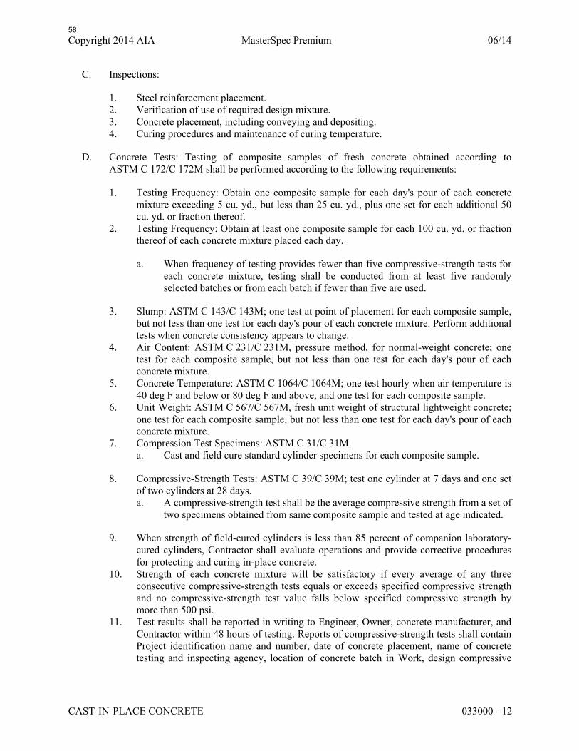
Copyright 2014 AIA MasterSpec Premium 06/14
CAST-IN-PLACE CONCRETE 033000 - 12
C. Inspections:
1. Steel reinforcement placement. 2. Verification of use of required design mixture. 3. Concrete placement, including conveying and depositing. 4. Curing procedures and maintenance of curing temperature.
D. Concrete Tests: Testing of composite samples of fresh concrete obtained according to ASTM C 172/C 172M shall be performed according to the following requirements:
1. Testing Frequency: Obtain one composite sample for each day's pour of each concrete mixture exceeding 5 cu. yd., but less than 25 cu. yd., plus one set for each additional 50 cu. yd. or fraction thereof.
2. Testing Frequency: Obtain at least one composite sample for each 100 cu. yd. or fraction thereof of each concrete mixture placed each day.
a. When frequency of testing provides fewer than five compressive-strength tests for each concrete mixture, testing shall be conducted from at least five randomly selected batches or from each batch if fewer than five are used.
3. Slump: ASTM C 143/C 143M; one test at point of placement for each composite sample, but not less than one test for each day's pour of each concrete mixture. Perform additional tests when concrete consistency appears to change.
4. Air Content: ASTM C 231/C 231M, pressure method, for normal-weight concrete; one test for each composite sample, but not less than one test for each day's pour of each concrete mixture.
5. Concrete Temperature: ASTM C 1064/C 1064M; one test hourly when air temperature is 40 deg F and below or 80 deg F and above, and one test for each composite sample.
6. Unit Weight: ASTM C 567/C 567M, fresh unit weight of structural lightweight concrete; one test for each composite sample, but not less than one test for each day's pour of each concrete mixture.
7. Compression Test Specimens: ASTM C 31/C 31M. a. Cast and field cure standard cylinder specimens for each composite sample.
8. Compressive-Strength Tests: ASTM C 39/C 39M; test one cylinder at 7 days and one set of two cylinders at 28 days. a. A compressive-strength test shall be the average compressive strength from a set of
two specimens obtained from same composite sample and tested at age indicated.
9. When strength of field-cured cylinders is less than 85 percent of companion laboratory-cured cylinders, Contractor shall evaluate operations and provide corrective procedures for protecting and curing in-place concrete.
10. Strength of each concrete mixture will be satisfactory if every average of any three consecutive compressive-strength tests equals or exceeds specified compressive strength and no compressive-strength test value falls below specified compressive strength by more than 500 psi.
11. Test results shall be reported in writing to Engineer, Owner, concrete manufacturer, and Contractor within 48 hours of testing. Reports of compressive-strength tests shall contain Project identification name and number, date of concrete placement, name of concrete testing and inspecting agency, location of concrete batch in Work, design compressive
58
Copyright 2014 AIA MasterSpec Premium 06/14
CAST-IN-PLACE CONCRETE 033000 - 13
strength at 28 days, concrete mixture proportions and materials, compressive breaking strength, and type of break for both 7- and 28-day tests.
12. Nondestructive Testing: Impact hammer, sonoscope, or other nondestructive device may be permitted by Engineer but will not be used as sole basis for approval or rejection of concrete.
13. Additional Tests: Testing and inspecting agency shall make additional tests of concrete when test results indicate that slump, air entrainment, compressive strengths, or other requirements have not been met, as directed by Engineer. Testing and inspecting agency may conduct tests to determine adequacy of concrete by cored cylinders complying with ASTM C 42/C 42M or by other methods as directed by Engineer.
14. Additional testing and inspecting, at Contractor's expense, will be performed to determine compliance of replaced or additional work with specified requirements.
15. Correct deficiencies in the Work that test reports and inspections indicate do not comply with the Contract Documents.
END OF SECTION 033000
59

OWNER:CITY OF INGLEWOOD1 MANCHESTER BLVD.P.O. BOX 6500INGLEWOOD, CA 90301
PROJECT INDEX
ENGINEER OF RECORD (EOR):MARTIN & MARTIN12499 W. COLFAX AVE.LAKEWOOD, CO 80215(303) 431-6100
FACADE ACCESS CONSULTANT:OLYMPIQUE FACADEACCESS CONSULTING (OFAC)23262 ENTERPRISE COURTLAKE FOREST, CA 92630(949) 309-2820
EXTERIOR BUILDING MAINTENANCE (EBM) EQUIPMENT SYSTEM
Inglewood City Hall
One W. Manchester Blvd, Inglewood, CA 90301
ARCHITECT OF RECORD:CHARLES LUCKMAN ASSOCIATES9220 SUNSET BOULEVARDLOS ANGELES, CA 90069
EB-16-021
26429 Rancho Parkway South #145, Lake Forest, CA 92630Phone: 949.309.2820 Fax: 949.613.5905
Website: www.facadeaccess.com
VV
DO
THIS DRAWING, ANY RELATED DOCUMENTS AND RELATED INFORMATION ARE THE PROPERTY OF OLYMPIQUE FACADE ACCESS CONSULTING. THEY MAY ONLY BE USED FOR THE SPECIFIC PURPOSE FOR WHICH THEY HAVE BEEN PROVIDED. NO REPRODUCTION, DUPLICATION OR DISCLOSURE OF THE DRAWING, DOCUMENTS AND INFORMATION IS PERMITTED WITHOUT THE PRIOR WRITTEN CONSENT OF OLYMPIQUE FACADE ACCESS CONSULTING.
0 25% DESIGN DEVELOPMENT SC03.02.17
5
Inglewood City Hall
11.02.16
One W. Manchester Blvd.
Inglewood, CA 90301
1 50% DESIGN DEVELOPMENT SC10.19.17
2 75% DESIGN DEVELOPMENT SC03.04.19
3 75% DESIGN DEVELOPMENT VV04.09.19
4 75% DESIGN DEVELOPMENT VV04.17.19
5 100% DESIGN DEVELOPMENT VV07.03.19
\\Oly
mpi
que-
nas\
elc\
Shar
ed\C
LIEN
TS\C
ity o
f Ing
lew
ood\
Ingl
ewoo
d Ci
ty H
all (
EB)\I
ngle
woo
d Ci
ty H
all (
EB) -
05
OFAC
\EB-
16-0
21 D
D 10
0%R5
.0.d
wg7
/3/2
019
4:57
:44
PM
FA0.0
N/A
COVER SHEET
FA0.0 COVER SHEETFA1.0 COMPOSITE ROOF PLANFA1.1 COMPOSITE ROOF PLANFA2.0 NORTH ELEVATIONFA3.0 WALL SECTION/ ENLARGED SECTIONFA9.0 DETAILSFA9.1 DETAILSFA9.2 DETAILSS-0.1 QA/QC NOTESS-1.0 ROOF PLAN RAILINGS-2.0 DETAILS
THIS SCOPE OF WORK INCLUDES THE DESIGN OF A NEW WINDOW CLEANING AND FACADE ACCESSEQUIPMENT SYSTEM TO MEET CURRENT REGULATIONS. NEW FACADE ACCESS EQUIPMENTINCLUDES BUT IS NOT LIMITED TO THE FOLLOWING:
1. NEW BMU2. NEW BMU TRACKS
ALL EQUIPMENT SHOWN ON THESE DRAWINGS IS CONCEPTUAL. THE ACTUAL SYSTEM &EQUIPMENT SHALL BE DESIGNED, FABRICATED AND INSTALLED BY AWARDED CONTRACTOR. ALLWORK SHALL BE PERFORMED IN CONFORMANCE WITH SPECIFICATION SECTION 11014 OR 112423AND THESE DRAWINGS.
1. THE CONTRACTOR SHALL BEAR RESPONSIBILITY FOR PROVIDING ALL WORK AND MATERIALS INACCORDANCE WITH APPLICABLE CODES AND STANDARDS (FEDERAL, STATE, AND COUNTY),HAVING JURISDICTION OVER SUCH WORK. ALL APPLICABLE REQUIREMENTS IN THESEREGULATIONS SHALL BE FOLLOWED THE SAME AS IF NOTED ON THE DRAWINGS.
2. THE CONTRACTOR AND SUBCONTRACTORS SHALL PERFORM ALL WORK IN STRICTCOMPLIANCE WITH THE CALIFORNIA OCCUPATION SAFETY AND HEALTH ACT.
3. CONTRACTOR IS FULLY RESPONSIBLE FOR LOCATING ALL EXISTING REINFORCING STEEL OROTHER ENCASED STEEL ASSEMBLIES PRIOR TO INSTALLATION OF ANCHORS OR DRILLEDHOLES, TO ENSURE THE EXISTING STEEL IS NOT DAMAGED. CONTRACTOR IS FULLYRESPONSIBLE FOR ALL WORK REQUIRED TO REPAIR DAMAGES CAUSED BY DRILLING AND/ORINSTALLATION OF ANCHORS.
4. ENGINEER OF RECORD / CONSULTANT WILL NOT SUPERVISE, DIRECT, CONTROL OF HAVEAUTHORITY OVER OR BE RESPONSIBLE FOR CONTRACTOR'S MEANS, METHODS, TECHNIQUES,SEQUENCES OR PROCEDURES OF CONSTRUCTION, OR THE SAFETY PRECAUTIONS ANDPROGRAMS INCIDENT THERETO, OR FOR ANY FAILURE OF CONTRACTOR TO COMPLY WITHLAWS AND REGULATIONS APPLICABLE TO THE FURNISHING OR PERFORMANCE OF THE WORK.
5. THE CONTRACTOR SHALL VERIFY THAT REQUIRED CLEARANCES ARE OBTAINED PRIOR TOCOMMENCEMENT OF THE WORK.
6. THE CONTRACTOR IS RESPONSIBLE FOR VERIFYING THE ACCURACY OF ALL DIMENSIONS FORBOTH EXISTING AND PROPOSED WORK PRIOR TO SYSTEM FABRICATION. CONTACTCONSULTANT IF ANY DIMENSIONS OR EXISTING BUILDING CONSTRUCTION VARIES FROM WHATIS SHOWN ON THESE DRAWINGS.
7. CONTRACTOR IS FULLY RESPONSIBLE FOR PATCHING AND WATERPROOFING ALLPENETRATIONS IN ROOF AND/OR WALL COVERINGS DUE TO INSTALLATION OF NEWASSEMBLIES.
8. AT NEW EQUIPMENT INSTALLATIONS, CONTRACTOR TO VERIFY THICKNESS OF ROOF SLAB,ROOFING MATERIAL, OR WALL CONSTRUCTION PRIOR TO EQUIPMENT FABRICATION TO ENSUREADEQUATE CLEARANCE WILL BE OBTAINED UPON INSTALLATION. CONTACT CONSULTANT IFADEQUATE CLEARANCES CANNOT BE OBTAINED.
9. PERFORM ALL WORK IN ACCORDANCE WITH LOCAL BUILDING CODES.10. DO NOT SCALE DRAWINGS. VERIFY DIMENSIONS IN FIELD PRIOR TO FABRICATION AND
INSTALLATION OF ASSEMBLIES.11. ALL LOADS SPECIFIED ON THESE DRAWINGS ARE WORKING LOADS, UNLESS NOTED
OTHERWISE. ALL COMPONENTS SHOWN ON THESE DRAWINGS SHALL BE DESIGNED TOSUPPORT THE WORKING LOADS SPECIFIED WITH A MINIMUM FACTOR OF SAFETY OF FOUR (4)AGAINST PERMANENT DEFORMATION OR FAILURE.
12. ALL STEEL ASSEMBLIES SHALL BE HOT DIP GALVANIZED AFTER FABRICATION AND PRIOR TOINSTALLATION.
13. ALL EXPOSED FIELD WELDS SHALL BE APPLIED WITH A COLD GALVANIZING SPRAY OREQUIVALENT CORROSIVE-RESISTANT SUBSTANCE.
14. PROVIDE SPECIAL INSPECTIONS OF ADHESIVE ANCHOR INSTALLATIONS, FIELD WELDING, ETC.AS REQUIRED BY BUILDING CODE.
15. COORDINATION WITH OTHER TRADE WORK IS MANDATORY.16. OPERATING PROCEDURES OUTLINE SHEET (OPOS) AS MAY BE REQUIRED BY CAL/OSHA FOR
THIS PROJECT IS NOT INCLUDED IN THIS SCOPE.17. CONTROLLED DESCENT APPARATUS EQUIPMENT, WORKER'S SAFETY LINES, HIGH REACH
WATER FED POLE, ARTICULATING BOOM LIFT AND SCISSOR LIFT, ARE NOT INCLUDED IN THISSCOPE.
18. THE STRUCTURAL ENGINEER OF RECORD FOR THE OVERALL PROJECT IS RESPONSIBLE FORCHECKING THE PRIMARY BUILDING STRUCTURE FOR LOADS TRANSFERRED TO IT BY THEEQUIPMENT AND WORKING CONDITIONS SHOWN IN THESE DRAWINGS.
CONSULTANT NOTES
ABBREVIATIONS
SHEET INDEX
PROJECT DESCRIPTION
100% Design Development Drawings
1. THE EXISTING STRUCTURE IS ADEQUATE TO SUPPORT THE LOADS ASSOCIATED WITH THEPROPOSED EQUIPMENT SHOWN ON THESE DRAWINGS BASED ON THE LOCATIONS ANDDIMENSIONS SHOWN.
2. THE NEW EQUIPMENT SHOWN ON THESE DRAWINGS IS CONCEPTUAL. THE FINAL DESIGN ANDENGINEERING OF ALL NEW EQUIPMENT SHALL BE BY AWARDED CONTRACTOR AND MUST BEDESIGNED TO ADEQUATELY TRANSMIT/DISTRIBUTE LOADS TO THE EXISTING STRUCTURE INACCORDANCE WITH THE EOR ANALYSIS AND MEET WEIGHT/LOAD REQUIREMENTS SPECIFIEDON THESE DRAWINGS.
ENGINEER OF RECORD (EOR) NOTES
1. STEEL & ALUMINUM WELDING TO BE DONE TO:a. ANSI STANDARDS SS-EN 729-1 TO 4;b. ANSI STANDARDS SS-EN 288-1 TO 8; SS-EN 287-1 TO 2;c. ISO ITR 1767-1 TO 4; ISO 9956-1 TO 4; ISO 9606-1 TO 4d. AMERICAN WELDING SOCIETY (AWS): D1.1 "STRUCTURAL WELDING CODE, STEEL"
2. STRUCTURAL STEEL TO CONFORM TO ASTM A500 GRADE B FOR HOLLOW STRUCTURALSECTIONS (HSS) AND ASTM A992 FOR WIDE FLANGES, OR APPROVED EQUAL.
3. PLATES AND ALL OTHER SHAPES SHALL CONFORM TO ASTM A36, OR APPROVED EQUAL,UNLESS SPECIFIED OTHERWISE HEREIN.
4. ALL STAINLESS STEEL PLATES TO BE TYPE 304 TO ASTM A666 (OR APPROVED EQUAL) WITH AMINIMUM YIELD OF 28.7 KSI AND AN ULTIMATE TENSILE STRENGTH OF 84 KSI.
5. ALL NON STAINLESS STEEL BOLTS SHALL BE GALVANIZED AND CONFORM TO ASTM A325. ALLNON STAINLESS STEEL NUTS AND WASHERS SHALL BE GALVANIZED AND CONFORM TO ASTMA563 AND F436 RESPECTIVELY.
6. ALL NON STAINLESS STEEL THREADED ROD TO CONFORM TO ASTM A449, OR APPROVEDEQUAL.
7. ALL STAINLESS STEEL BOLTS AND THREADED ROD TO BE TYPE B8 TO ASTM A193/A193M-91A(OR APPROVED EQUAL) WITH A MINIMUM YIELD OF 29.7 KSI AND AN ULTIMATE TENSILESTRENGTH OF 84 KSI WITH COMPATIBLE NUTS AND WASHERS.
8. ALL ALUMINUM COMPONENTS TO BE GRADE HA.4 GS11N-T6 (6061-T6) OR GHA.5 S11R-T6(6351-T6).
9. STEEL WELD FILLER MATERIAL TO BE ER70 S-6 AWS A5.18.10. ALUMINUM WELD FILLER MATERIAL TO BE ER4043 ANSI/AWS A5.1011. WIRE ROPE SHALL BE MIN. 5/16" DIA. XXIP IWRC GALVANIZED OR STAINLESS STEEL WITH MIN.
BREAKING STRENGTH OF 9,000#, UNLESS NOTED OTHERWISE.12. SLIDING RINGS SHALL GALVANIZED OR STAINLESS STEEL MATERIAL; CROSBY G-341 X 1/2" OR
EQ. WITH MIN. ULTIMATE LOAD LIMIT OF 5,000#.13. SHACKLES SHALL BE BOLT-TYPE, GALVANIZED OR STAINLESS STEEL MATERIAL; CROSBY
G-2130 X 5/8" OR EQ. WITH MIN. ULTIMATE LOAD LIMIT OF 5,000#.14. THIMBLES SHALL BE STAINLESS STEEL MATERIAL.15. OVAL SLEEVES SHALL BE ZINC PLATED OR STAINLESS STEEL MATERIAL.
MATERIAL SPECIFICATIONS
A AMPAFF ABOVE FINISHED FLOORAFR ABOVE FINISHED ROOFARCH ARCHITECTURALASSY ASSEMBLYBMU BUILDING MAINTENANCE UNITB.O. BOTTOM OFB.O.S. BOTTOM OF STRUCTURECDA CONTROLLED DESCENT APPARATUSCL CENTERLINECONC CONCRETEDIA DIAMETER(E) EXISTINGEA EACHEOR ENGINEER OF RECORDETFE ETHYLENE TETRAFLUOROETHYLENE
(POLYMER USED FOR PNEUMATICROOF PANELS)
FOW FACE OF WALLGC GENERAL CONTRACTORGL GRIDLINEHB HOSE BIBBHDG HOT DIPPED GALVANIZEDHLL HORIZONTAL LIFE LINEI.D. INNER DIAMETERISF INSIDE FACE
L.F. LINEAR FOOT (SURFACE LENGTH)MAX MAXIMUMMFR MANUFACTURERMIN MINIMUMMTL MATERIALNTS NOT TO SCALE(N) NEWNTS NOT TO SCALENIC NOT IN CONTRACTO.C. ON CENTERO.D. OUTER DIAMETEROPP OPPOSITEORIG ORIGINALQTY QUANTITYREF REFERENCESIM SIMILARSTRUC STRUCTURALT.O. TOP OFT.O.P. TOP OF PARAPETT.O.R. TOP OF ROOFT.O.S. TOP OF STRUCTURETYP TYPICALUNO UNLESS NOTED OTHERWISEUSM UNSCHEDULED MAINTENANCEV VOLTVIF VERIFY IN FIELD
60

20'
J
H
F
E
C
B
13 12 10 8 6 4
24'
24'
24'
20'
20' 24' 24' 24' 20'
14B22
14B22
8WF24
8WF24
8WF24
8WF24
8B15
8WF1
7
8WF1
7
8WF1
7
14B22
8WF24
8B15
8WF24
8WF24
8WF17
14B2
2
8WF2
4
8WF1
7
8WF2
4
8WF1
7
8WF2
4
14B2
2
8WF2
4
8WF2
4
8WF2
4
8WF24
8WF17
8WF2
4
8WF1
7
14B2
2
8WF24
8WF24
14B22
8B15
8WF24
8WF24
14B22
8WF24
8WF24
14B22
8WF24
8WF17
8WF2
4
8WF1
7
14B2
2
8WF2
4
8WF2
4
14B2
2
8WF2
4
8WF2
4
14B2
2
8WF2
4
8WF2
4
14B2
2
8WF24
8WF17
8WF2
4
8WF1
7
PENTHOUSE ROOF(±267'-6")
ROOF(±264'-0")
ROOF(±264'-0")
3RD FLOOR(±151'-6")
3RD FLOOR(±151'-6")3RD FLOOR
(±151'-6")
3RD FLOOR(±151'-6")
9TH FLOORROOF
(±235'-6")
9TH FLOORROOF
(±235'-6")
9TH FLOORROOF
(±235'-6")
9TH FLOOR ROOF(±235'-6")
(E) EYEBOLT TO BE DEMOLISHED. SEE DETAIL 1/FA9.2
WINDOW LINE TO BE ACCESSED BY EQUIPMENT
HB (E) WATER LOCATION TO BE VIF
(E) POWER LOCATION TO BE VIF: 480V (60Hz) 30ACENTRAL ELECTIC BOX WITH MAGNETOTHERMIC
(E) BEAM TRACK TO BE DEMOLISHED. SEE DETAIL2/FA9.2
RECESSED WINDOW LINE TO BE ACCESSEDBY EQUIPMENT
(N) SPLICE. SEE DETAILS 5/FA9.1
(N) BUILDING MAINTENANCE UNIT (BMU),SEE DETAIL 1/FA9.0
(N) BEAM @ CORNERS, SEE DETAIL 3 & 4/FA9.1
(N) BEAM TRACK. SEE DETAILS 1&2/FA9.1
LEGEND
EB-16-021
26429 Rancho Parkway South #145, Lake Forest, CA 92630Phone: 949.309.2820 Fax: 949.613.5905
Website: www.facadeaccess.com
VV
DO
THIS DRAWING, ANY RELATED DOCUMENTS AND RELATED INFORMATION ARE THE PROPERTY OF OLYMPIQUE FACADE ACCESS CONSULTING. THEY MAY ONLY BE USED FOR THE SPECIFIC PURPOSE FOR WHICH THEY HAVE BEEN PROVIDED. NO REPRODUCTION, DUPLICATION OR DISCLOSURE OF THE DRAWING, DOCUMENTS AND INFORMATION IS PERMITTED WITHOUT THE PRIOR WRITTEN CONSENT OF OLYMPIQUE FACADE ACCESS CONSULTING.
0 25% DESIGN DEVELOPMENT SC03.02.17
5
Inglewood City Hall
11.02.16
One W. Manchester Blvd.
Inglewood, CA 90301
1 50% DESIGN DEVELOPMENT SC10.19.17
2 75% DESIGN DEVELOPMENT SC03.04.19
3 75% DESIGN DEVELOPMENT VV04.09.19
4 75% DESIGN DEVELOPMENT VV04.17.19
5 100% DESIGN DEVELOPMENT VV07.03.19
\\Oly
mpi
que-
nas\
elc\
Shar
ed\C
LIEN
TS\C
ity o
f Ing
lew
ood\
Ingl
ewoo
d Ci
ty H
all (
EB)\I
ngle
woo
d Ci
ty H
all (
EB) -
05
OFAC
\EB-
16-0
21 D
D 10
0%R5
.0.d
wg7
/3/2
019
4:57
:45
PM
FA1.0
AS NOTED
COMPOSITE ROOF PLAN
Scale: 1/16" = 1' - 0"
DEMOLITION ROOF PLAN1 N
61

20'
J
H
F
E
C
B
13 12 10 8 6 4
24'
24'
24'
20'
20' 24' 24' 24' 20'
14B22
14B22
8WF24
8WF24
8WF24
8WF24
8B15
8WF1
7
8WF1
7
8WF1
7
14B22
8WF24
8B15
8WF24
8WF24
8WF17
14B2
2
8WF2
4
8WF1
7
8WF2
4
8WF1
7
8WF2
4
14B2
2
8WF2
4
8WF2
4
8WF2
4
8WF24
8WF17
8WF2
4
8WF1
7
14B2
2
8WF24
8WF24
14B22
8B15
8WF24
8WF24
14B22
8WF24
8WF24
14B22
8WF24
8WF17
8WF2
4
8WF1
7
14B2
2
8WF2
4
8WF2
4
14B2
2
8WF2
4
8WF2
4
14B2
2
8WF2
4
8WF2
4
14B2
2
8WF24
8WF17
8WF2
4
8WF1
7
PENTHOUSE ROOF(±267'-6")
ROOF(±264'-0")
ROOF(±264'-0")
3RD FLOOR(±151'-6")
3RD FLOOR(±151'-6")3RD FLOOR
(±151'-6")
3RD FLOOR(±151'-6")
1FA3.0
9TH FLOORROOF
(±235'-6")
9TH FLOORROOF
(±235'-6")
9TH FLOORROOF
(±235'-6")
9TH FLOOR ROOF(±235'-6")
1FA2.0
TYP.
BMU STORAGELOCATION
24' CRADLE STORAGELOCATION
±2'
-9"
(E) EYEBOLT TO BE DEMOLISHED. SEE DETAIL 1/FA9.2
WINDOW LINE TO BE ACCESSED BY EQUIPMENT
HB (E) WATER LOCATION TO BE VIF
(E) POWER LOCATION TO BE VIF: 480V (60Hz) 30ACENTRAL ELECTIC BOX WITH MAGNETOTHERMIC
(E) BEAM TRACK TO BE DEMOLISHED. SEE DETAIL2/FA9.2
RECESSED WINDOW LINE TO BE ACCESSEDBY EQUIPMENT
(N) SPLICE. SEE DETAILS 5/FA9.1
(N) BUILDING MAINTENANCE UNIT (BMU),SEE DETAIL 1/FA9.0
(N) BEAM @ CORNERS, SEE DETAIL 3 & 4/FA9.1
(N) BEAM TRACK. SEE DETAILS 1&2/FA9.1
LEGEND
EB-16-021
26429 Rancho Parkway South #145, Lake Forest, CA 92630Phone: 949.309.2820 Fax: 949.613.5905
Website: www.facadeaccess.com
VV
DO
THIS DRAWING, ANY RELATED DOCUMENTS AND RELATED INFORMATION ARE THE PROPERTY OF OLYMPIQUE FACADE ACCESS CONSULTING. THEY MAY ONLY BE USED FOR THE SPECIFIC PURPOSE FOR WHICH THEY HAVE BEEN PROVIDED. NO REPRODUCTION, DUPLICATION OR DISCLOSURE OF THE DRAWING, DOCUMENTS AND INFORMATION IS PERMITTED WITHOUT THE PRIOR WRITTEN CONSENT OF OLYMPIQUE FACADE ACCESS CONSULTING.
0 25% DESIGN DEVELOPMENT SC03.02.17
5
Inglewood City Hall
11.02.16
One W. Manchester Blvd.
Inglewood, CA 90301
1 50% DESIGN DEVELOPMENT SC10.19.17
2 75% DESIGN DEVELOPMENT SC03.04.19
3 75% DESIGN DEVELOPMENT VV04.09.19
4 75% DESIGN DEVELOPMENT VV04.17.19
5 100% DESIGN DEVELOPMENT VV07.03.19
\\Oly
mpi
que-
nas\
elc\
Shar
ed\C
LIEN
TS\C
ity o
f Ing
lew
ood\
Ingl
ewoo
d Ci
ty H
all (
EB)\I
ngle
woo
d Ci
ty H
all (
EB) -
05
OFAC
\EB-
16-0
21 D
D 10
0%R5
.0.d
wg7
/3/2
019
4:57
:50
PM
FA1.1
N/A
COMPOSITE ROOF PLAN
Scale: 1/16" = 1' - 0"
COMPOSITE ROOF PLAN1 N
62

1ST FLOOREL. 119.50'
2ND FLOOREL. 137.50'
3RD FLOOREL. 151.50'
4TH FLOOREL. 165.50'
5TH FLOOREL. 179.50'
6TH FLOOREL. 193.50'
7TH FLOOREL. 207.50'
8TH FLOOREL. 221.50'
9TH FLOOREL. 235.50'
PENTHOUSE FLOOREL. 249.50'
TOP PARAPET & PENTHOUSE ROOFEL. 267.50'
(N) BMU1FA9.0
WINDOWS TO BE ACCESSED FROM EXTERIORBY SUSPENDED OPERATIONS (WORK CRADLE/ BASKET)
24' CRADLE
EB-16-021
26429 Rancho Parkway South #145, Lake Forest, CA 92630Phone: 949.309.2820 Fax: 949.613.5905
Website: www.facadeaccess.com
VV
DO
THIS DRAWING, ANY RELATED DOCUMENTS AND RELATED INFORMATION ARE THE PROPERTY OF OLYMPIQUE FACADE ACCESS CONSULTING. THEY MAY ONLY BE USED FOR THE SPECIFIC PURPOSE FOR WHICH THEY HAVE BEEN PROVIDED. NO REPRODUCTION, DUPLICATION OR DISCLOSURE OF THE DRAWING, DOCUMENTS AND INFORMATION IS PERMITTED WITHOUT THE PRIOR WRITTEN CONSENT OF OLYMPIQUE FACADE ACCESS CONSULTING.
0 25% DESIGN DEVELOPMENT SC03.02.17
5
Inglewood City Hall
11.02.16
One W. Manchester Blvd.
Inglewood, CA 90301
1 50% DESIGN DEVELOPMENT SC10.19.17
2 75% DESIGN DEVELOPMENT SC03.04.19
3 75% DESIGN DEVELOPMENT VV04.09.19
4 75% DESIGN DEVELOPMENT VV04.17.19
5 100% DESIGN DEVELOPMENT VV07.03.19
\\Oly
mpi
que-
nas\
elc\
Shar
ed\C
LIEN
TS\C
ity o
f Ing
lew
ood\
Ingl
ewoo
d Ci
ty H
all (
EB)\I
ngle
woo
d Ci
ty H
all (
EB) -
05
OFAC
\EB-
16-0
21 D
D 10
0%R5
.0.d
wg7
/3/2
019
4:57
:55
PM
FA2.0
1/16"=1'-0"
NORTH ELEVATION
Scale: 1/16" = 1'-0"
NORTH ELEVATION1
63

3RD FLOOREL. 151.50'
4TH FLOOREL. 165.50'
5TH FLOOREL. 179.50'
6TH FLOOREL. 193.50'
7TH FLOOREL. 207.50'
8TH FLOOREL. 221.50'
9TH FLOOREL. 235.50'
PENTHOUSE FLOOREL. 249.50'
TOP PARAPET &PENTHOUSE ROOF
EL. 267.50'2-
13
2' TYP.
±6'-9"
(N) BMU
24' CRADLE
T.O. FINISHED ROOF(±264'-0")
13
2'-2" 2'-2"
9'-10" MAX. REACHROTATE 130°
(N) BEAM TRACK PER STRUCTURAL
(E) TIEBACK EYEBOLT TO BE DEMOLISHED
(E) MECHANICAL
8" 1'-1"
4'-4" 1'-9"
(E) COLUMN BEYOND
ROTATE 90°
2'-0" TYP.
T.O. PARAPET(±267'-6")
1-5FA9.1
1FA9.2
(N) CURB PER STRUCTURAL, TYP.
(N) BMU 1FA9.0
EB-16-021
26429 Rancho Parkway South #145, Lake Forest, CA 92630Phone: 949.309.2820 Fax: 949.613.5905
Website: www.facadeaccess.com
VV
DO
THIS DRAWING, ANY RELATED DOCUMENTS AND RELATED INFORMATION ARE THE PROPERTY OF OLYMPIQUE FACADE ACCESS CONSULTING. THEY MAY ONLY BE USED FOR THE SPECIFIC PURPOSE FOR WHICH THEY HAVE BEEN PROVIDED. NO REPRODUCTION, DUPLICATION OR DISCLOSURE OF THE DRAWING, DOCUMENTS AND INFORMATION IS PERMITTED WITHOUT THE PRIOR WRITTEN CONSENT OF OLYMPIQUE FACADE ACCESS CONSULTING.
0 25% DESIGN DEVELOPMENT SC03.02.17
5
Inglewood City Hall
11.02.16
One W. Manchester Blvd.
Inglewood, CA 90301
1 50% DESIGN DEVELOPMENT SC10.19.17
2 75% DESIGN DEVELOPMENT SC03.04.19
3 75% DESIGN DEVELOPMENT VV04.09.19
4 75% DESIGN DEVELOPMENT VV04.17.19
5 100% DESIGN DEVELOPMENT VV07.03.19
\\Oly
mpi
que-
nas\
elc\
Shar
ed\C
LIEN
TS\C
ity o
f Ing
lew
ood\
Ingl
ewoo
d Ci
ty H
all (
EB)\I
ngle
woo
d Ci
ty H
all (
EB) -
05
OFAC
\EB-
16-0
21 D
D 10
0%R5
.0.d
wg7
/3/2
019
4:58
:00
PM
FA3.0
N/A
SECTION/ ENLARGED SECTION
Scale: 1/16" = 1'-0"
TYPICAL SECTION @ BMU1
Scale: 1/2" = 1'-0"
ENLARGED SECTION @ BMU2
64

T.O. PARAPET(±267'-6")
T.O. FINISHED ROOF(±264'-0")
9'-10" MAX. REACH
ROTATE 130°
(N) BEAM TRACK
4'-4"
ROTATE 90°
TOP VIEW
24'-0
" CRA
DLE
±4'
-4"
24'-0" CRADLE
(N) BEAM TRACKS
(N) CURB
1-5FA9.1
(N) CURB PER STRUCTURAL, TYP.
DEAD WEIGHT = 23,260 LBRATED LOAD (Q) = 750 LB
MAX. ALLOWABLE LOADS
EB-16-021
26429 Rancho Parkway South #145, Lake Forest, CA 92630Phone: 949.309.2820 Fax: 949.613.5905
Website: www.facadeaccess.com
VV
DO
THIS DRAWING, ANY RELATED DOCUMENTS AND RELATED INFORMATION ARE THE PROPERTY OF OLYMPIQUE FACADE ACCESS CONSULTING. THEY MAY ONLY BE USED FOR THE SPECIFIC PURPOSE FOR WHICH THEY HAVE BEEN PROVIDED. NO REPRODUCTION, DUPLICATION OR DISCLOSURE OF THE DRAWING, DOCUMENTS AND INFORMATION IS PERMITTED WITHOUT THE PRIOR WRITTEN CONSENT OF OLYMPIQUE FACADE ACCESS CONSULTING.
0 25% DESIGN DEVELOPMENT SC03.02.17
5
Inglewood City Hall
11.02.16
One W. Manchester Blvd.
Inglewood, CA 90301
1 50% DESIGN DEVELOPMENT SC10.19.17
2 75% DESIGN DEVELOPMENT SC03.04.19
3 75% DESIGN DEVELOPMENT VV04.09.19
4 75% DESIGN DEVELOPMENT VV04.17.19
5 100% DESIGN DEVELOPMENT VV07.03.19
\\Oly
mpi
que-
nas\
elc\
Shar
ed\C
LIEN
TS\C
ity o
f Ing
lew
ood\
Ingl
ewoo
d Ci
ty H
all (
EB)\I
ngle
woo
d Ci
ty H
all (
EB) -
05
OFAC
\EB-
16-0
21 D
D 10
0%R5
.0.d
wg7
/3/2
019
4:58
:05
PM
FA9.0
N/A
DETAIL
Scale: 1/2" = 1'-0"
(N) BMU1
65

(N) CURB PER STRUCTURAL
(E) CONCRETE SLAB PERSTRUCTURAL
(N) SPLICE PLATEPER STRUCTURAL
(E) BEAM PER STRUCTURAL
(N) BEAM PER STRUCTURAL
(N) BOLTS PER STRUCTURAL
FRONT VIEW
NOTE: REFER TO DETAIL 2/S-2.0FOR ADDITIONAL INFORMATION
(E) CONCRETE COLUMN PERSTRUCTURAL
PER
EOR
PER
EOR
(N) BOLTS PER STRUCTURAL
(N) PLATE PER STRUCTURAL
WELD PER STRUCTURAL
WELD PER STRUCTURAL
(N) PLATE PER STRUCTURAL
PER EOR
PER EOR
TOP VIEW
FRONT VIEW
NOTE: REFER TO DETAIL 5/S-2.0FOR ADDITIONAL INFORMATION
(N) BEAM PER STRUCTURAL
(N) CURB PER STRUCTURAL
(N) HILTI ANCHORPER STRUCTURAL
PER
EOR
(E) CONCRETE SLABPER STRUCTURAL
(N) BOLT PER STRUCTURAL
(N) BEAM PER STRUCTURAL
PER EOR
PER
EOR
TOP VIEW
FRONT VIEW
NOTE: REFER TO DETAIL 3/S-2.0FOR ADDITIONAL INFORMATION
PER
EOR
(E) PIPE PER STRUCTURAL
WELD PER STRUCTURAL
(N) BOLTS PER STRUCTURAL
PER EOR
(N) PLATE PER STRUCTURAL
PER
EOR
TOP VIEW
FRONT VIEW
NOTE: REFER TO DETAIL 4/S-2.0FOR ADDITIONAL INFORMATION
PER EOR
PER EOR
(N) L BRACKET PER STRUCTURAL
(N) BOLTS PER STRUCTURAL
(N) CURB PER STRUCTURAL
(E) CONCRETE SLAB
(E) BEAM PER STRUCTURAL
(N) BOLTS PER STRUCTURAL
(N) PLATE PER STRUCTURALPER EOR
PER
EOR
PER EOR
PER
EOR
PER
EOR
FRONT VIEW
NOTE: REFER TO DETAIL 1/S-2.0FOR ADDITIONAL INFORMATION
(N) BEAM PER STRUCTURAL
EB-16-021
26429 Rancho Parkway South #145, Lake Forest, CA 92630Phone: 949.309.2820 Fax: 949.613.5905
Website: www.facadeaccess.com
VV
DO
THIS DRAWING, ANY RELATED DOCUMENTS AND RELATED INFORMATION ARE THE PROPERTY OF OLYMPIQUE FACADE ACCESS CONSULTING. THEY MAY ONLY BE USED FOR THE SPECIFIC PURPOSE FOR WHICH THEY HAVE BEEN PROVIDED. NO REPRODUCTION, DUPLICATION OR DISCLOSURE OF THE DRAWING, DOCUMENTS AND INFORMATION IS PERMITTED WITHOUT THE PRIOR WRITTEN CONSENT OF OLYMPIQUE FACADE ACCESS CONSULTING.
0 25% DESIGN DEVELOPMENT SC03.02.17
5
Inglewood City Hall
11.02.16
One W. Manchester Blvd.
Inglewood, CA 90301
1 50% DESIGN DEVELOPMENT SC10.19.17
2 75% DESIGN DEVELOPMENT SC03.04.19
3 75% DESIGN DEVELOPMENT VV04.09.19
4 75% DESIGN DEVELOPMENT VV04.17.19
5 100% DESIGN DEVELOPMENT VV07.03.19
\\Oly
mpi
que-
nas\
elc\
Shar
ed\C
LIEN
TS\C
ity o
f Ing
lew
ood\
Ingl
ewoo
d Ci
ty H
all (
EB)\I
ngle
woo
d Ci
ty H
all (
EB) -
05
OFAC
\EB-
16-0
21 D
D 10
0%R5
.0.d
wg7
/3/2
019
4:58
:10
PM
FA9.1
N/A
DETAILS
Scale: 1" = 1'-0"
(N) BEAM TRACK @ CURB AND CROSS BEAM1
Scale: 1 1/2" = 1'-0"
(N) BEAM TRACK @ CURB2Scale: 1" = 1'-0"
(N) BEAM TRACK @ COLUMN3
Scale: 1 1/2" = 1'-0"
(N) BEAM TRACK @ PIPE4
Scale: 1" = 1'-0"
(N) BEAM SPLICE5
66

(E) TIEBACK EYEBOLT TO BE DEMOLISHED
T.O. ROOF
(E) CURB TO BE DEMOLISHED
NOTE:1. WATER PROOFING BY OTHERS2. DAMAGE CONCRETE SLAB TO BEINFILLED
T.O. ROOF
(E) BEAM TRACK TO BE DEMOLISHED
(E) CURB TO BE DEMOLISHED
NOTE:1. WATER PROOFING BY OTHERS2. DAMAGE CONCRETE SLAB TO BEINFILLED
EB-16-021
26429 Rancho Parkway South #145, Lake Forest, CA 92630Phone: 949.309.2820 Fax: 949.613.5905
Website: www.facadeaccess.com
VV
DO
THIS DRAWING, ANY RELATED DOCUMENTS AND RELATED INFORMATION ARE THE PROPERTY OF OLYMPIQUE FACADE ACCESS CONSULTING. THEY MAY ONLY BE USED FOR THE SPECIFIC PURPOSE FOR WHICH THEY HAVE BEEN PROVIDED. NO REPRODUCTION, DUPLICATION OR DISCLOSURE OF THE DRAWING, DOCUMENTS AND INFORMATION IS PERMITTED WITHOUT THE PRIOR WRITTEN CONSENT OF OLYMPIQUE FACADE ACCESS CONSULTING.
0 25% DESIGN DEVELOPMENT SC03.02.17
5
Inglewood City Hall
11.02.16
One W. Manchester Blvd.
Inglewood, CA 90301
1 50% DESIGN DEVELOPMENT SC10.19.17
2 75% DESIGN DEVELOPMENT SC03.04.19
3 75% DESIGN DEVELOPMENT VV04.09.19
4 75% DESIGN DEVELOPMENT VV04.17.19
5 100% DESIGN DEVELOPMENT VV07.03.19
\\Oly
mpi
que-
nas\
elc\
Shar
ed\C
LIEN
TS\C
ity o
f Ing
lew
ood\
Ingl
ewoo
d Ci
ty H
all (
EB)\I
ngle
woo
d Ci
ty H
all (
EB) -
05
OFAC
\EB-
16-0
21 D
D 10
0%R5
.0.d
wg7
/3/2
019
4:58
:15
PM
FA9.2
N/A
DETAILS
Scale: 1-1/2" = 1'-0"
(E) TIEBACK EYEBOLT & CURB DEMOLITION1
Scale: 1-1/2" = 1'-0"
(E) BEAM TRACK & CURB DEMOLITION2
67

1) CONNECTIONS:1A) PROVIDE CONNECTIONS AS SHOWN IN THE DETAILS HEREIN.
2) WELDING REQUIREMENTS:2A) WELDERS: HAVE IN POSSESSION CURRENT EVIDENCE OF PASSING THE APPROPRIATE AWS. QUALIFICATION TESTS.
2B) MINIMUM WELDS: AISC SPECIFICATION, NOT LESS THAN 3/16” FILLET, CONTINUOUS UNLESS OTHERWISE NOTED.
2C)WELD SIZES AND LENGTHS CALLED FOR ON THE DRAWINGS ARE THE NET EFFECTIVE REQUIRED. INCREASE WELD SIZE IF GAPS EXIST AT THE FAYING SURFACE.
2D)WELD SIZES SHALL BE AS SHOWN UNLESS A GREATER SIZE IS REQUIRED BY ANSI/AISC 360-05 TABLES J2.3 AND J2.4.
2E) ALL GROOVE WELDS SHALL BE COMPLETE PENETRATION UNLESS NOTED.
2F) FIELD WELDING SYMBOLS INDICATE SEQUENCE CONSIDERED DURING DESIGN. THE CONTRACTOR SHALL REQUEST APPROVAL FROM THE ENGINEER TO MODIFY WELD INSTALLATION LOCATION INDICATED ON THE DOCUMENTS:- FROM SHOP TO FIELD - FROM FIELD TO SHOP
3) STRUCTURAL STEEL INSTALLATION:3A) UNLESS INDICATED OTHERWISE, SNUG TIGHTEN ALL JOINTS AS DEFINED BY AISC
1) CODES AND STANDARDS:1A) GENERAL DESIGN- CALIFORNIA BUILDING CODE 2016
2) FALL PROTECTION LOADS2A) LOADS PROVIDED BY OLYMPIQUE FACADE ACCESS CONSULTANTS ON DRAWINGS DATED 04/17/2019
1) GENERAL:1A) ENGINEER: REFERENCES ON THE STRUCTURAL DRAWINGS TO ‘ENGINEER’ MEAN THE STRUCTURAL ENGINEER OF RECORD. OTHER ENTITIES ARE SPECIFICALLY NOTED AS “MECHANICAL ENGINEER”, ETC.
1B) STRUCTURAL ELEMENTS ARE CENTERED ON GRID LINES AND GRID LINE INTERSECTIONS UNLESS DIMENSIONED OTHERWISE.
2) EXISTING STRUCTURES:2A) CONTRACT DOCUMENTS HAVE BEEN PREPARED USING AVAILABLE DRAWINGS AND SITE OBSERVATION AS PERMITTED BY ACCESS RESTRICTIONS DURING DESIGN.
2B) DURING CONSTRUCTION, THE CONTRACTOR MAY ENCOUNTER EXISTING CONDITIONS WHICH ARE NOT NOW KNOWN OR ARE AT VARIANCE WITH PROJECT DOCUMENTATION. CONTRACTOR SHALL NOTIFY THE ENGINEER OF ALL CONDITIONS NOT PER THE CONTRACT DOCUMENTS. EXAMPLES INCLUDE:- SIZES OR DIMENSIONS OTHER THAN THOSE SHOWN- DAMAGE OR DETERIORATION TO MATERIALS AND COMPONENTS- CONDITIONS OF INSTABILITY OR LACK OF SUPPORT- ITEMS NOTED AS EXISTING ON THE DRAWINGS BUT NOT FOUND IN THE FIELD
2C)PREPARE DIMENSIONAL DRAWINGS OF ALL DISCOVERED ITEMS.
2D)CONTRACTOR SHALL FIELD VERIFY ALL EXISTING STRUCTURAL CONDITIONS PRIOR TO SUBMITTING SHOP DRAWINGS.
2E) CONTRACTOR SHALL MAKE ALLOWANCE FOR THE RESOLUTION OF SUCH DISCOVERIES IN THE CONSTRUCTION SCHEDULE.
2F) SUBMIT A DIMENSIONED DRAWING OF ALL NEW OPENINGS THROUGH EXISTING STRUCTURE AND SECURE APPROVAL PRIOR TO CUTTING. DRAWING SHALL SHOW VERTICAL & HORIZONTAL LOCATION AND SIZE OF PROPOSED OPENING.
3) USE OF DRAWINGS:3A) DO NOT SCALE DRAWINGS.
3B) DETAILS ON DRAWINGS TAKE PRECEDENCE OVER GENERAL NOTES AND TYPICAL DETAILS.
3C)DETAILS NOTED TYPICAL APPLY TO ALL SIMILAR CONDITIONS. WHERE NO SPECIFIC DETAILS ARE SHOWN, CONSTRUCTION SHALL CONFORM TO SIMILAR WORK ELSEWHERE ON THE PROJECT.
3D)WHERE DISCREPANCIES OCCUR BETWEEN PLANS, DETAILS, GENERAL NOTES AND SPECIFICATIONS:- CONTACT THE ENGINEER PRIOR TO PROCEEDING WITH CONSTRUCTION- THE MORE STRINGENT REQUIREMENTS SHALL GOVERN FOR BIDDING / PRICING
4) TEMPORARY CONDITIONS:4A) CONTRACTOR’S CONSTRUCTION AND/OR ERECTION SEQUENCES SHALL RECOGNIZE AND CONSIDER THE EFFECTS OF THERMAL MOVEMENTS OF STRUCTURAL ELEMENTS DURING THE CONSTRUCTION PERIOD.
5) SUBMITTALS AND SUBSTITUTIONS:5A) SUBMITTALS: - IF THE CONTRACTOR REQUESTS A CHANGE FROM THE STRUCTURAL DRAWINGS, IT SHALL BE APPROVED AND DESIGNED BY MARTIN/MARTIN, INC. PRIOR TO SUBMITTING SHOP DRAWINGS. VARIATION SHALL BE INDICATED ON THE SHOP DRAWINGS. CONTRACTOR SHALL COMPENSATE MARTIN/MARTIN, INC. FOR MAKING THE CHANGE.- CONSTRUCTION DOCUMENTS SHALL NOT BE REPRODUCED FOR USE IN SUBMITTALS- ALL SHOP DRAWINGS SHALL REFERENCE THE STRUCTURAL DRAWING NUMBER AND DETAIL USED TO PREPARE THE SUBMITTAL
5B) SUBSTITUTIONS: ENGINEER'S APPROVAL SHALL BE SECURED FOR ALL SUBSTITUTIONS
5C)NONCONFORMANCE: NOTIFY ENGINEER OF CONDITIONS NOT CONSTRUCTED PER THE CONTRACT DOCUMENTS PRIOR TO PROCEEDING WITH CORRECTIVE WORK. SUBMIT PROPOSED REPAIR TO THE ENGINEER FOR ACCEPTANCE. CONTRACTOR SHALL COMPENSATE MARTIN/MARTIN, INC. FOR DESIGNING THE REPAIR.
6) CAL-OSHA STANDARDS:6A) THE STRUCTURE IS DESIGNED TO FUNCTION AS A UNIT UPON COMPLETION. NOTHING SHOWN ON THE STRUCTURAL DRAWINGS SHALL BE CONSTRUED AS ELIMINATING THE NEED FOR THE CONTRACTOR TO COMPLY WITH ALL CAL-OSHA REQUIREMENTS.
6B) WHERE THE STRUCTURAL DRAWINGS APPEAR TO CONFLICT WITH CAL-OSHA REQUIREMENTS, THE STRUCTURAL DRAWINGS REPRESENT FINAL CONDITIONS ONLY. THE CONTRACTOR SHALL ADD ALL ERECTION FRAMING NECESSARY TO COMPLY WITH CAL-OSHA.
7) CONSTRUCTION ENGINEERING:7A) THE STRUCTURE DEFINED ON THE CONTRACT DOCUMENTS HAS BEEN DESIGNED ONLY FOR LOADS ANTICIPATED ON THE STRUCTURE DURING ITS SERVICE LIFE. PROVIDE ALL REQUIRED ENGINEERING AND OTHER MEASURES TO ACHIEVE THE MEANS, METHODS, AND SEQUENCES OF WORK. SUCH ENGINEERING MAY INCLUDE, BUT IS NOT LIMITED TO:- LAYOUT- DESIGN OF CONCRETE MIXES- WELD PROCEDURES- SURVEYING TO VERIFY CONSTRUCTION TOLERANCES- EVALUATION OF TEMPORARY CONSTRUCTION LOADS ON STRUCTURE DUE TO EQUIPMENT AND MATERIALS- STRUCTURAL ENGINEERING TO RESIST ANY OTHER LOADS NOT IDENTIFIED ON DESIGN DRAWINGS
8) COORDINATION:STRUCTURAL DRAWINGS ARE NOT STAND-ALONE DOCUMENTS AND ARE INTENDED TO BE USED IN CONJUNCTION WITH DRAWINGS FROM OTHER CONSULTANTS. THE CONTRACTOR SHALL COORDINATE ALL REQUIREMENTS OF THE CONTRACT DOCUMENTS INTO SHOP DRAWINGS AND WORK.
1) GENERAL:1A) ALL WORK SHALL CONFORM WITH ACI 301-10, UNLESS NOTED OTHERWISE IN DRAWINGS OR PROJECT SPECIFICATIONS.
2) REINFORCING MATERIALS:2A) USE ASTM A615 Fy=60KSI REINFORCING BARS.
3) STRUCTURAL CONCRETE MIX REQUIREMENTS:3A) ALL CONCRETE SHALL BE NORMAL-WEIGHT AND PROPORTIONED TO MEET THE FOLLOWING PROPERTIES: - 28-DAY STRENGTH f’c = 4.0 ksi- MAXIMUM AMOUNT OF FLY ASH = 25% - MAXIMUM WATER TO CEMENT RATIO, INCLUDING FLY ASH = 0.50- MAXIMUM AGGREGATE SIZE = 3/4”
4) NON-SHRINK GROUT:4A) CONFORM TO ASTM C1107
4B) ACHIEVE 6000 PSI COMPRESSIVE STRENGTH AT 28 DAYS.
1) PERSONNEL REQUIREMENTS:1A) THE CONTRACTOR SHALL ARRANGE AN ANCHOR MANUFACTURER’S REPRESENTATIVE TO PROVIDE ONSITE INSTALLATION TRAINING FOR ALL OF THEIR ANCHORING PRODUCTS SPECIFIED. SUBMIT DOCUMENTED CONFIRMATION THAT ALL OF THE CONTRACTOR’S PERSONNEL WHO INSTALL ANCHORS HAVE PASSED THE TRAINING COURSE PRIOR TO THE COMMENCEMENT OF INSTALLING ANCHORS.
2) INSTALLATION REQUIREMENTS:2A) ALL POST-INSTALLED ANCHORS SHALL BE INSTALLED ACCORDING TO MANUFACTURER'S PRINTED INSTALLATION INSTRUCTIONS AND PER MANUFACTURER'S ON-SITE TRAINING.
- DRY CONCRETE, UNLESS NOTED OTHERWISE.- CONCRETE TEMPERATURE AT TIME OF INSTALLATION THROUGH CURE TIME MUST BE WITHIN THE TEMPERATURE RANGE SPECIFIED IN MANUFACTURER'S PRINTED INSTALLATION INSTRUCTION FOR ADHESIVE GEL AND CURE TIMES.- ANCHOR HOLES TO BE HAMMER DRILLED AND CLEANED.- CONCRETE MUST BE AT LEAST 21 DAYS OLD BEFORE INSTALLATION OF ANCHORS.
2B) THE POSITION OF EXISTING REINFORCING BARS IN THE CONCRETE STRUCTURE SHALL BE LOCATED PRIOR TO INSTALLING POST INSTALLED ANCHORS OR REINFORCEMENT. EXISTING REINFORCEMENT SHALL BE LOCATED USING A SCANNER, GPR, X-RAY, CHIPPING OR OTHER MEANS. DO NOT DAMAGE OR CUT EXISTING REINFORCEMENT.
3) SUBSTITUTION REQUESTS:3A) SUBSTITUTION REQUESTS FOR ALTERNATE PRODUCTS MUST BE APPROVED IN WRITING BY THE STRUCTURAL ENGINEER PRIOR TO USE. CONTRACTOR SHALL PROVIDE CALCULATIONS AND PRODUCT DATA DEMONSTRATING THAT THE SUBSTITUTED PRODUCT IS IN COMPLIANCE WITH THE RELEVANT BUILDING CODES, LOAD RESISTANCE, INSTALLATION CATEGORY, IN-SERVICE TEMPERATURE AND INSTALLATION TEMPERATURE OF THE SPECIFIED PRODUCT.
Ma
rtin
/Mar
tin
, In
c. c
on
sid
ers
th
at
de
sig
n d
ata
is o
nly
in
its
fin
al f
orm
on
plo
tted
dra
win
gs
wit
h o
rig
ina
l sig
na
ture
s a
nd
pro
fes
sio
nal
cer
tifi
cati
on
be
ing
vis
ibly
pre
sen
t o
n t
he
dra
win
gs.
Dat
a s
up
pli
ed v
ia c
om
pu
ter
gen
era
ted
fo
rma
t d
oes
no
t c
on
tain
th
is a
pp
rova
l o
r c
ert
ific
atio
n. T
he
rece
ive
r o
f e
lec
tro
nic
ally
tra
ns
mit
ted
dra
win
gs
is r
es
po
ns
ible
fo
r v
erif
yin
g t
he
info
rma
tio
n c
on
tain
ed w
ith
in t
he
ele
ctro
nic
da
ta a
gai
ns
t th
e re
cord
ed
or
ap
pro
ved
do
cum
ents
.
Th
e u
se o
f el
ect
roni
cally
tra
nsm
itte
d d
raw
ings
is c
on
sid
ere
d to
be
at
your
ow
n r
isk.
Mar
tin/M
artin
, In
c. a
ssu
mes
no
resp
onsi
bili
ty f
or
any
cla
ims
or d
am
age
s re
sulti
ng
from
yo
ur u
se o
f th
is in
form
atio
n. E
lect
ron
ic in
form
atio
n is
pro
vid
ed f
or th
e co
nve
nie
nce
of
the
re
cip
ient
on
ly.
Th
e re
cip
ien
t of t
his
file
ag
ree
s th
at t
he in
form
atio
n m
ay
no
t be
tran
sfer
red
to a
ny o
the
r p
arty
.
PROJECT NO:
DATE:
REVISIONS
SHEET TITLE:
SHEET NUMBER:
MM
JO
B #
:P
RIN
CIP
AL:
EO
R:
PR
OJE
CT
MA
NA
GE
R:
DE
SIG
NE
RS
:LE
AD
RE
VIT
TE
CH
:D
AT
E P
RIN
TE
D:
FIL
E P
AT
H:
7/3/
2019
11:
48:4
2 A
MC
:\Pro
j\BS
17.0
268.
S.0
1-O
ne M
anch
este
r B
oule
vard
- S
19_L
Wal
do.rv
t
ING
LEW
OO
D C
ITY
HA
LL
1 W
. MA
NC
HE
ST
ER
BLV
D. I
NG
LEW
OO
D, C
ALI
FO
RN
IA 9
0301
BS17.0268.S.01
7/1/2019
S-0.0
GENERAL NOTES
© MARTIN/MARTIN 2018
I. IV
AN
OV
A
L. W
ALD
O
E. G
UG
LIE
LMO
BS
17.0
268.
S.0
1
L. W
ALD
O
M. S
TE
AR
NS
STEEL NOTES
OTHER SHAPES A36 36 58 --
WF, WT A992 50 65 --
WELDINGELECTRODES,THICKNESS OFTHINNER PART > 0.1INCHES (12 GA)
E70 PER AWS
PLATES A36 36 58 --
BOLTSF3125 - TYPE
A325 OR F1852-- 120
BOLTS ARE 3/4"Ø UNO, USETENSION- CONTROLLED WHEREPOSSIBLE
STEEL ELEMENT ASTM/TYPEFy
(KSI)Fu (KSI) COMMENTS
STEEL MATERIAL TABLE
DESIGN CRITERIAGENERAL NOTESCONCRETE NOTES
POST-INSTALLED ANCHOR NOTES
NO. ISSUE DATE
1 PERMIT AND BID 7/1/2019
7/03/2020
68

QUALITY ASSURANCE GENERAL NOTES
1. GENERAL:1A. SCOPE OF WORK- THE OWNER WILL ENGAGE A QUALIFIED INSPECTION AND TESTING AGENCY(S) TO PERFORM SPECIAL INSPECTIONS FOR ALL STRUCTURAL MEMBERS AND ASSEMBLIES AS NOTED HEREIN.- SPECIAL INSPECTIONS ARE IN ADDITION TO INSPECTIONS BY THE AUTHORITY HAVING JURISDICTION REQUIRED BY IBC 2015 SECTION 110.- REFER TO ARCH/MECH DRAWINGS FOR ADDITIONAL SPECIAL INSPECTION AND TESTING THAT MAY BE REQUIRED.- SPECIAL INSPECTIONS AND TESTING ARE APPLICABLE TO ALL REVISIONS AND/OR FUTURE WORK ADDED BY AMENDMENTS TO THESE DOCUMENTS.
1B. DEFINITIONS- SPECIAL INSPECTOR: THE AGENCY ENGAGED BY THE OWNER AND APPROVED BY THE AUTHORITY HAVING JURISDICTION TO ACT AS THE DESIGNATED REPRESENTATIVE TO PERFORM INSPECTIONS.- SPECIAL INSPECTION: INSPECTION PERFORMED BY THE SPECIAL INSPECTOR ACCORDING TO IBC 2015 SECTION 1704 TO ENSURE COMPLIANCE WITH APPROVED CONSTRUCTION DOCUMENTS AND REFERENCED STANDARDS. - (P) PERIODIC INSPECTION: THE PART-TIME OR INTERMITTENT OBSERVATION BY THE SPECIAL INSPECTOR OF WORK BEING PERFORMED. SPECIAL INSPECTOR SHALL BE PRESENT IN THE AREA WHERE THE WORK IS BEING PERFORMED. OBSERVATION OF ALL WORK (100% VISUAL) SHALL BE MADE AT THE COMPLETION OF THE WORK. - (C) CONTINUOUS INSPECTION: THE FULL-TIME OBSERVATION BY THE SPECIAL INSPECTOR OF WORK BEING PERFORMED. SPECIAL INSPECTOR SHALL BE PRESENT IN THE AREA WHERE THE WORK IS BEING PERFORMED. OBSERVATION OF ALL WORK (100% VISUAL) SHALL BE MADE AT THE COMPLETION OF THE WORK.
1C. DEFICIENCIES IN WORK- CORRECT DEFICIENCIES IN WORK THAT TESTS AND INSPECTIONS INDICATE DO NOT COMPLY WITH THE CONTRACT DOCUMENTS AND REFERENCED STANDARDS.- ALL COST OF ADDITIONAL TESTING AND/OR INSPECTIONS FOR CORRECTIVE WORK SHALL BE BORNE BY THE CONTRACTOR.
2. SHOP FABRICATIONS:2A. GENERAL- PERFORM INSPECTIONS AND TESTING FOR ALL SHOP FABRICATED STRUCTURAL MEMBERS AND ASSEMBLIES AS NOTED HEREIN. SPECIAL INSPECTOR SHALL PERFORM SPECIAL INSPECTIONS AND TESTING UNLESS THE FABRICATOR IS REGISTERED AND APPROVED BY THE AUTHORITY HAVING JURISDICTION TO PERFORM SUCH WORK WITHOUT SPECIAL INSPECTION OR FABRICATION HAS A CURRENT ICC-ES EVALUATION REPORT. - SPECIAL INSPECTOR SHALL VERIFY THE FABRICATOR MAINTAINS AND FOLLOWS DETAILED SHOP FABRICATION AND QUALITY CONTROL PROCEDURES, UNLESS FABRICATOR IS REGISTERED AND APPROVED.- AT THE COMPLETION OF FABRICATION, THE APPROVED FABRICATOR SHALL SUBMIT A CERTIFICATE OF COMPLIANCE TO THE AUTHORITY HAVING JURISDICTION ACCORDING TO IBC 2015 SECTION 1704.2.5.2.- APPROVED FABRICATORS MAY PERFORM TESTING NOTED HEREIN EXCEPT THAT NONDESTRUCTIVE TESTING (NDT) SHALL ONLY BE PERFORMED BY PERSONNEL WITH QUALIFICATIONS THAT MEET OR EXCEED THE CRITERIA OF AWS D1.1 SUBCLAUSE 6.14.6 AND AMERICAN SOCIETY FOR NONDESTRUCTIVE TESTING (ASNT) SNT-TC-1A OR ASNT CP-189.
2B. SHOP FABRICATIONS INCLUDED- SHOP FABRICATED STRUCTURAL STEEL
STATEMENT OF STRUCTURAL SPECIAL
INSPECTIONS AND TESTING
Ma
rtin
/Mar
tin
, In
c. c
on
sid
ers
th
at
de
sig
n d
ata
is o
nly
in
its
fin
al f
orm
on
plo
tted
dra
win
gs
wit
h o
rig
ina
l sig
na
ture
s a
nd
pro
fes
sio
nal
cer
tifi
cati
on
be
ing
vis
ibly
pre
sen
t o
n t
he
dra
win
gs.
Dat
a s
up
pli
ed v
ia c
om
pu
ter
gen
era
ted
fo
rma
t d
oes
no
t c
on
tain
th
is a
pp
rova
l o
r c
ert
ific
atio
n. T
he
rece
ive
r o
f e
lec
tro
nic
ally
tra
ns
mit
ted
dra
win
gs
is r
es
po
ns
ible
fo
r v
erif
yin
g t
he
info
rma
tio
n c
on
tain
ed w
ith
in t
he
ele
ctro
nic
da
ta a
gai
ns
t th
e re
cord
ed
or
ap
pro
ved
do
cum
ents
.
Th
e u
se o
f el
ect
roni
cally
tra
nsm
itte
d d
raw
ings
is c
on
sid
ere
d to
be
at
your
ow
n r
isk.
Mar
tin/M
artin
, In
c. a
ssu
mes
no
resp
onsi
bili
ty f
or
any
cla
ims
or d
am
age
s re
sulti
ng
from
yo
ur u
se o
f th
is in
form
atio
n. E
lect
ron
ic in
form
atio
n is
pro
vid
ed f
or th
e co
nve
nie
nce
of
the
re
cip
ient
on
ly.
Th
e re
cip
ien
t of t
his
file
ag
ree
s th
at t
he in
form
atio
n m
ay
no
t be
tran
sfer
red
to a
ny o
the
r p
arty
.
PROJECT NO:
DATE:
REVISIONS
SHEET TITLE:
SHEET NUMBER:
MM
JO
B #
:P
RIN
CIP
AL:
EO
R:
PR
OJE
CT
MA
NA
GE
R:
DE
SIG
NE
RS
:LE
AD
RE
VIT
TE
CH
:D
AT
E P
RIN
TE
D:
FIL
E P
AT
H:
7/3/
2019
11:
48:4
2 A
MC
:\Pro
j\BS
17.0
268.
S.0
1-O
ne M
anch
este
r B
oule
vard
- S
19_L
Wal
do.rv
t
ING
LEW
OO
D C
ITY
HA
LL
1 W
. MA
NC
HE
ST
ER
BLV
D. I
NG
LEW
OO
D, C
ALI
FO
RN
IA 9
0301
BS17.0268.S.01
7/1/2019
S-0.1
QA/QC NOTES
© MARTIN/MARTIN 2018
I. IV
AN
OV
A
L. W
ALD
O
E. G
UG
LIE
LMO
BS
17.0
268.
S.0
1
L. W
ALD
O
M. S
TE
AR
NS
- AFTER INSTALLATIONOF ATTACHEDASSEMBLY
100% VISUAL -VERIFY NUMBER, EDGE DISTANCES, ANDANCHOR FLUSH WITH AND PERPENDICULARTO THE RECEIVING SURFACE
- DURING INSTALLATIONOF ANCHOR
C ICC-ES REPORT
CONTINUOUS INSPECTION REQUIREDREGARDLESS IF PERIODIC INSPECTION ISPERMITTED BY ICC-ES REPORT. VERIFY HOLEDIMENSIONS, HOLE CLEANING, ANCHOREMBEDMENT, EDGE DISTANCES ANDSPACING
- PRIOR TOINSTALLATION OFANCHOR
EACH ANCHOR ICC-ES REPORT
VERIFY TYPE, DIAMETER, LENGTH, FINISH,AND BASE MATERIAL. VERIFY SOLIDGROUTED AREA AROUND ANCHORS INGROUTED MASONRY. VERIFY MAXIMUMIMPACT WRENCH TORQUE RATING FORSCREW ANCHORS
- PRIOR TO START OFWORK - ICC-ES REPORT
REVIEW CONTRACTOR'S INSTALLATIONPROCEDURE
EXPANSION ANCHORS, SLEEVE ANCHORS, SCREW ANCHORS
ITEM FREQUENCY STANDARD CRITERIA
POST-INSTALLED ANCHORS/REINFORCING STEEL SPECIALINSPECTIONS
OBSERVE - OBSERVE THESE ITEMS ON A RANDOM BASISPERFORM - THESE INSPECTIONS SHALL BE PERFORMED FOR EACH WELDED CONNECTION, EACHBOLTED CONNECTION, AND EACH ITEM, PRIOR TO ACCEPTANCE
- DOCUMENT ACCEPTANCE ORREJECTION OF BOLTEDCONNECTIONS
PERFORM
DOCUMENTACCEPTANCE
OR REJECTIONOF WELDEDMEMBER OR
JOINT
-
AFTER BOLTING
- PROPER STORAGE FORFASTENER COMPONENTS OBSERVE
AISC 360,CHAPTER N
-
- CONNECTING ELEMENTSMEET REQUIREMENTS,INCLUDING HOLE REPARATIONAND FAYING SURFACE
OBSERVEAISC 360,
CHAPTER N-
- PROPER FASTENERS ANDBOLTING PROCEDURESELECTED FOR JOINT DETAIL
OBSERVEAISC 360,
CHAPTER N-
- FASTENERS MARKS INACCORDANCE WITH ASTMREQUIREMENTS
OBSERVEAISC 360,
CHAPTER N-
- REVIEW MANUFACTURERCERTIFICATIONS FORFASTENER MATERIALS
PERFORMAISC 360,
CHAPTER N-
PRIOR TO BOLTING
- DOCUMENT ACCEPTANCE ORREJECTION OF WELDEDMEMBER OR JOINT
PERFORMAISC 360,
CHAPTER N-
- REPAIR ACTIVITIESPERFORM
AISC 360,CHAPTER N
-
- K-AREAPERFORM
AISC 360,CHAPTER N
-
- ARC STRIKESPERFORM
AISC 360,CHAPTER N
-
- WELDS MEET VISUALACCEPTANCE CRITERIA
PERFORMAISC 360,
CHAPTER N,AWS D1.1
WHERE INSPECTOR OBSERVESQUESTIONABLE WELDS,NON-DESTRUCTIVE TESTING SHALL BEPERFORMED
- SIZE, LENGTH, AND LOCATIONOF WELDS PERFORM
AISC 360,CHAPTER N
-
- WELDS CLEANEDOBSERVE
AISC 360,CHAPTER N
-
AFTER WELDING
- WELDING TECHNIQUES -SINGLE PASS WELDS OBSERVE
AISC 360,CHAPTER N
-
- ENVIRONMENTALCONDITIONS, AND WPSFOLLOWED
OBSERVEAISC 360,
CHAPTER N-
- NO WELDING OVER CRACKEDTACK WELDS OBSERVE
AISC 360,CHAPTER N
-
- CONTROL AND HANDLING OFWELDING CONSUMABLES OBSERVE
AISC 360,CHAPTER N
-
- USE OF QUALIFIED WELDERSOBSERVE
AISC 360,CHAPTER N
-
DURING WELDING
- WELDER IDENTIFICATIONSYSTEM OBSERVE
AISC 360,CHAPTER N
-
- MATERIAL IDENTIFICATIONOBSERVE
AISC 360,CHAPTER N
-
- FIT UP OF WELDS, INCLUDINGJOINT GEOMETRY, ANDCONFIGURATIONS AND FINISHOF ACCESS HOLES
OBSERVEAISC 360,
CHAPTER N-
- REVIEW MANUFACTURERCERTIFICATIONS FORWELDING CONSUMABLES ANDWELDING PROCEDURESPECIFICATIONS
PERFORMAISC 360,
CHAPTER N-
PRIOR TO WELDING
- PRIOR TO FABRICATION ORERECTION
PERFORMAISC 360,
CHAPTER N
REVIEW MATERIAL TEST REPORTSAND CERTIFICATIONS FORSTRUCTURAL STEEL, FASTENERS,ANCHOR RODS, HEADED STUDANCHORS
ITEMINSPECTION
TASKSTANDARD CRITERIA/REMARKS
STRUCTURAL STEEL INSPECTIONS
- CURINGP
ACI 31826.5.3-26.5.5
-
- PLACEMENT OFCONCRETE C ACI 318 26.5.2 -
- FORMWORK PRIOR TOPLACEMENT OFCONCRETE
P ACI 318 26.11.1 INSPECT FIRST POUR
- MIX DESIGNEACH DAY -
VERIFY USE OF APPROVED DESIGN MIXTUREFOR EACH MIX
CONCRETE
- PRIOR TO PLACEMENTOF CONCRETE
100% -
VERIFY TYPE, FINISH, DIAMETER, LENGTH,QUANTITY, EMBEDMENT LENGTH, SPACINGAND EDGE DISTANCES. VERIFY USE OFPLACING TEMPLATE WHERE SPECIFIED
BOLTS AND EMBEDMENTS
- FIELD BENDING P ACI 301 3.3.2.8 -
- PRIOR TO PLACEMENTOF CONCRETE 100%
- DURING PLACEMENTP
ACI 318 7.7, 8.7,11.7, 20.2, 20.4,20.6, 25, 26.6
VERIFY GRADE, FINISH, SIZE, BAR QUANTITY,LOCATION, SPACING, COVER, HOOKLENGTHS, SPLICE LENGTH, SPLICELOCATIONS, BEND DIAMETERS, SURFACECONDITION, AND SUPPORT
REINFORCING STEEL
ITEM FREQUENCY STANDARD CRITERIA
STRUCTURAL CONCRETE SPECIAL INSPECTIONS (ACI 318-14)
- TENSION TEST
FIRST 3 AND1% OF
REMAINING
ASTM E488STATIC TENSION
TEST THE INSTALLATION OF THE FIRST 3OF EACH TYPE, BASE MATERIAL, ANDPOSITION (DOWN, HORIZONTAL,OVERHEAD). OBSERVE ASTM E488MINIMUM EDGE DISTANCES FORDETERMINING TEST LOCATIONS. SUBMITPROPOSED TESTLOCATIONS AND REQUESTS FORREQUIREDTENSION TEST LOAD VALUES TOENGINEER
ADHESIVE ANCHORS, REINFORCING STEEL ANCHORED INTO HARDENED CONCRETE
- TORQUE TEST
100% -
TEST ANCHOR WITH CALIBRATED TORQUEWRENCH TO 100% OF THE INSTALLATIONTORQUE NOTED IN ICC-ES REPORT.ATTAIN SPECIFIED TORQUE WITHIN 1/2TURN OF THE NUT
EXPANSION ANCHORS, SLEEVE ANCHORS, SCREW ANCHORS
ITEM FREQUENCY STANDARD CRITERIA
POST-INSTALLED ANCHOR/REINFORCING STEEL TESTING
NO. ISSUE DATE
1 PERMIT AND BID 7/1/2019
7/03/2020
69

468101213
J
H
F
E
C
B
20'-0" 24'-0" 24'-0" 24'-0" 20'-0"
112'-0"
20'-0"
24'-0"
24'-0"
24'-0"
20'-0"
112'-0"
W8
W8
W8
W8
W8
W8
W8
W8
W8
W8
W8
W8
W8
W8
W8
W8
W8
W8
W8
W8
W8
W8
W8
W8
W8
W8
W8
W8
W8
W8
W8W8
W8
W8
W8
W8
W8
W8
W8
W8
W8
W8
W8
W8x40 W8x40
W8x40
(E)PIPE COLUMN
W8x40
2
S-2.0
4
S-2.0
TYP @ CORNER BEAM
1
1
1
1
5
S-2.0
TYP @ CORNER BEAM
1
1
1
1
2
S-2.0
2
S-2.0 TYPICAL AT NEW RAIL AND CURB OVER EXISTING BEAM BELOW
2
S-2.0
NORTH
(E) STEEL BEAMS BELOW, TYP AT PERIMETER OF MECHANICAL WELLS; FIELD VERIFY THAT CENTERLINE OF EXISTING BEAMS AND RAILS ARE < 12" APART
(E) GRATING OVER MECHANICAL WELL BELOW, (5) LOCATIONS ALONG SOUTH FACE
EXISTING STEEL BEAMS BELOW RAIL AND DECK, TYPICAL. FIELD VERIFY ALL MEMBERS.
DEMOLISH EXISTING INNER AND OUTER RAILS AND CURBS COMPLETELY. INSTALL NEW W12x22 RAIL TO MATCH LOCATION AND BEND RADIUS OF EXISTING RAILS. GC TO COORDINATE BEAM ALIGNMENT WITH BMU MANUFACTURER'S REQUIRED TOLERANCES. FIELD LOCATE RAIL SPLICES DIRECTLY OVER SUPPORTING STEEL MEMBERS; SPLICE RAIL PER . 1/S-2.0
(E)PIPE COLUMN(E)PIPE COLUMN
(E)PIPE COLUMN
EXISTING GRIDS AND DIMENSIONS SHOWN HERE ARE TO BE FIELD VERIFIED
W8
W8
W8
W8
W8
W8
W8
W8
W8
W8
W8
W8
W8
W8
W8
W8
3
S-2.0 TYPICAL AT NEW RAIL AND CURB BETWEEN EXISTING BEAMS
3
S-2.0
3
S-2.0
3
S-2.0TYPICAL AT NEW RAIL AND CURB BETWEEN EXISTING BEAMS
TYPICAL AT NEW RAIL AND CURB OVER EXISTING BEAM BELOW
TYPICAL AT NEW RAIL AND CURB OVER EXISTING BEAM BELOW
TYPICAL AT NEW RAIL AND CURB BETWEEN EXISTING BEAMS
TYPICAL AT NEW RAIL AND CURB BETWEEN EXISTING BEAMS
TYPICAL AT NEW RAIL AND CURB OVER EXISTING BEAM BELOW
EXISTING EXTERIOR WALL SYSTEM SHOWN FOR REFERENCE ONLY
W8 BELOW
W10 BELOW
W8 BELOW
W10 BELOW
W8 BELOW
W10 BELOW
W8 BELOW
W10 BELOW
W8 BELOW
W10 BELOW
KEYNOTE LEGEND:
1 REINFORCE EXISTING BEAMS PER 6/S-2.0
Ma
rtin
/Mar
tin
, In
c. c
on
sid
ers
th
at
de
sig
n d
ata
is o
nly
in
its
fin
al f
orm
on
plo
tted
dra
win
gs
wit
h o
rig
ina
l sig
na
ture
s a
nd
pro
fes
sio
nal
cer
tifi
cati
on
be
ing
vis
ibly
pre
sen
t o
n t
he
dra
win
gs.
Dat
a s
up
pli
ed v
ia c
om
pu
ter
gen
era
ted
fo
rma
t d
oes
no
t c
on
tain
th
is a
pp
rova
l o
r c
ert
ific
atio
n. T
he
rece
ive
r o
f e
lec
tro
nic
ally
tra
ns
mit
ted
dra
win
gs
is r
es
po
ns
ible
fo
r v
erif
yin
g t
he
info
rma
tio
n c
on
tain
ed w
ith
in t
he
ele
ctro
nic
da
ta a
gai
ns
t th
e re
cord
ed
or
ap
pro
ved
do
cum
ents
.
Th
e u
se o
f el
ect
roni
cally
tra
nsm
itte
d d
raw
ings
is c
on
sid
ere
d to
be
at
your
ow
n r
isk.
Mar
tin/M
artin
, In
c. a
ssu
mes
no
resp
onsi
bili
ty f
or
any
cla
ims
or d
am
age
s re
sulti
ng
from
yo
ur u
se o
f th
is in
form
atio
n. E
lect
ron
ic in
form
atio
n is
pro
vid
ed f
or th
e co
nve
nie
nce
of
the
re
cip
ient
on
ly.
Th
e re
cip
ien
t of t
his
file
ag
ree
s th
at t
he in
form
atio
n m
ay
no
t be
tran
sfer
red
to a
ny o
the
r p
arty
.
PROJECT NO:
DATE:
REVISIONS
SHEET TITLE:
SHEET NUMBER:
MM
JO
B #
:P
RIN
CIP
AL:
EO
R:
PR
OJE
CT
MA
NA
GE
R:
DE
SIG
NE
RS
:LE
AD
RE
VIT
TE
CH
:D
AT
E P
RIN
TE
D:
FIL
E P
AT
H:
7/3/
2019
11:
48:4
3 A
MC
:\Pro
j\BS
17.0
268.
S.0
1-O
ne M
anch
este
r B
oule
vard
- S
19_L
Wal
do.rv
t
ING
LEW
OO
D C
ITY
HA
LL
1 W
. MA
NC
HE
ST
ER
BLV
D. I
NG
LEW
OO
D, C
ALI
FO
RN
IA 9
0301
BS17.0268.S.01
7/1/2019
S-1.0
ROOF PLANRAILING
© MARTIN/MARTIN 2018
I. IV
AN
OV
A
L. W
ALD
O
E. G
UG
LIE
LMO
BS
17.0
268.
S.0
1
L. W
ALD
O
M. S
TE
AR
NS
1/8" = 1'-0"
ROOF PLAN
NO. ISSUE DATE
1 PERMIT AND BID 7/1/2019
7/03/2020
70

A
A
A
A
A
A
RAIL BEAM; SEE PLAN
PL3/8x6x1'-1 W/ (8) 3/4" BOLTS W/ HORIZONTAL SLOTTED HOLES IN BEAM
NEW CURB, DEMO (E) CURB
(E) CONCRETE
SLAB
(4) 3/4" Ø ROD
WT4x10.5x0'-9"
1 1/2"3"
3 1/4"3"1 1/2"
2"
1 1/
2"
3"
1 1/
2"
(E) BEAM; SEE
PLAN
2
S-2.0
1/4" MAX GAP
3" TYP 1 1/2" ES
DOUBLE NUT & WASHER
DOUBLE NUT & WASHER AT UNDERSIDE
NUT & WASHER AT TOP SIDE
ALL EXPOSED STEEL TO BE HOT DIPPED GALVANIZED
TOP OF NEW RAIL
SEE PLAN FOR TOLERANCE NOTES
8" MIN
VA
RIE
S
(E) CONCRETE SLAB
(E) BEAM, SEE PLAN
NOTES1. SEE FOR MORE INFORMATION1/S-2.0
NEW CURB, DEMO (E) CURB
TOP OF NEW RAIL
SPLICE PLATE AS OCCURS
ELEVATION VARIES
SEE FOR REINFORCEMENT INFORMATION
3/S-2.0
SEE PLAN FOR TOLERANCE NOTES
TOP OF (E) RAIL
DEMOLISHED
(E) W8 BEAM, SEE PLAN
WT4x6.5x5'-0" CENTERED ON (E)W8 WEB; SCRIBE WT STEM IF NEEDED TO FIT TIGHT
1/4 2-121/4 2-12
TYPICAL
1/4 81/4 8
EACH END
(E) CONCRETE
COLUMN
PL1/2x10x0'-10" EACH SIDE
(2) 5/8"Ø HILTI KWIK BOLT TZ w/ 3.25" EMBEDMENT
1 1/
2"4"
4 1/
2" M
IN
3/163/16
3/16FIELD WELDOPTION
COPE AS REQUIRED BASED ON CLEARANCE BETWEEN (E) COLUMN AND (E) ROOF DECK
PL1/2x6x0'-6"
3" M
IN
6" BEARING ON EXISITNG COLUMN, GROUT BELOW FOR SOLID BEARING
6 81/128"
5/165/16
1 1/2" MIN3" MAX
1 1/
2" M
IN, T
YP
3" M
IN
PL3/8x4x0'-6"
(E) 3"Ø PIPE
COLUMN
(2) 3/4" Ø BOLTS
(E) PIPE COLUMN IS LOCATED INSIDE PARTITION WALL, REMOVE PARTITION MATERIAL TO EXPOSE COLUMN
1 1/2"
VA
RIE
S
(E) CONCRETE
SLAB
NOTES1. SEE AND FOR MORE INFORMATION1/S-2.0
NEW CIP CONCRETE CURB
(2) #3 CONT TOP AND BOTTOM
#4 @ 2'-0 OC, ADHESIVE ANCHOR W/ HILTI HIT 200
ROUGHEN TO 1/4" AMPLITUDE
(2) 3/4" BOLT @ 4'-0" OC, EMBEDMENT = 4"
CO
VE
R1
1/2"
4"
STAGGER BOLTS 4" MINIMUM
3"
2/S-2.0
1"
Ma
rtin
/Mar
tin
, In
c. c
on
sid
ers
th
at
de
sig
n d
ata
is o
nly
in
its
fin
al f
orm
on
plo
tted
dra
win
gs
wit
h o
rig
ina
l sig
na
ture
s a
nd
pro
fes
sio
nal
cer
tifi
cati
on
be
ing
vis
ibly
pre
sen
t o
n t
he
dra
win
gs.
Dat
a s
up
pli
ed v
ia c
om
pu
ter
gen
era
ted
fo
rma
t d
oes
no
t c
on
tain
th
is a
pp
rova
l o
r c
ert
ific
atio
n. T
he
rece
ive
r o
f e
lec
tro
nic
ally
tra
ns
mit
ted
dra
win
gs
is r
es
po
ns
ible
fo
r v
erif
yin
g t
he
info
rma
tio
n c
on
tain
ed w
ith
in t
he
ele
ctro
nic
da
ta a
gai
ns
t th
e re
cord
ed
or
ap
pro
ved
do
cum
ents
.
Th
e u
se o
f el
ect
roni
cally
tra
nsm
itte
d d
raw
ings
is c
on
sid
ere
d to
be
at
your
ow
n r
isk.
Mar
tin/M
artin
, In
c. a
ssu
mes
no
resp
onsi
bili
ty f
or
any
cla
ims
or d
am
age
s re
sulti
ng
from
yo
ur u
se o
f th
is in
form
atio
n. E
lect
ron
ic in
form
atio
n is
pro
vid
ed f
or th
e co
nve
nie
nce
of
the
re
cip
ient
on
ly.
Th
e re
cip
ien
t of t
his
file
ag
ree
s th
at t
he in
form
atio
n m
ay
no
t be
tran
sfer
red
to a
ny o
the
r p
arty
.
PROJECT NO:
DATE:
REVISIONS
SHEET TITLE:
SHEET NUMBER:
MM
JO
B #
:P
RIN
CIP
AL:
EO
R:
PR
OJE
CT
MA
NA
GE
R:
DE
SIG
NE
RS
:LE
AD
RE
VIT
TE
CH
:D
AT
E P
RIN
TE
D:
FIL
E P
AT
H:
7/3/
2019
11:
48:4
4 A
MC
:\Pro
j\BS
17.0
268.
S.0
1-O
ne M
anch
este
r B
oule
vard
- S
19_L
Wal
do.rv
t
ING
LEW
OO
D C
ITY
HA
LL
1 W
. MA
NC
HE
ST
ER
BLV
D. I
NG
LEW
OO
D, C
ALI
FO
RN
IA 9
0301
BS17.0268.S.01
7/1/2019
S-2.0
DETAILS
© MARTIN/MARTIN 2018
I. IV
AN
OV
A
L. W
ALD
O
E. G
UG
LIE
LMO
BS
17.0
268.
S.0
1
L. W
ALD
O
M. S
TE
AR
NS
1" = 1'-0"1RAIL SPLICE AND ANCHOR TOCROSSBEAM
1 1/2" = 1'-0"2SECTION AT CURB AT (E)CROSSBEAM
3" = 1'-0"6 (E) BEAM REINFORCEMENT
1" = 1'-0"5CORNER BEAM @ (E) CONCRETECOLUMN
1 1/2" = 1'-0"4 CORNER BEAM @ (E) PIPE COLUMN
1 1/2" = 1'-0"3 SECTION AT CURB
NO. ISSUE DATE
1 PERMIT AND BID 7/1/2019
7/03/2020
71

RFB-0116
BIDDER'S PROPOSAL AND STATEMENT PAGE CITY OF INGLEWOOD,
WINDOW CLEANING EQUIPMENT EXTERIOR BUILDING MAINTENANCE (EBM) EQUIPMENT FAÇADE ACCESS
EQUIPMENT To the Mayor and City Council Members City of Inglewood Inglewood, CA 90301 The undersigned declares that he/she has carefully examined the location of the proposed work and has otherwise satisfied himself/herself as to the nature and location of the work, and is fully informed as to all conditions and matters which can in any way affect the work or cost thereof, that he/she has examined the Specifications and Plans, and has read the accompanying "SCOPE OF WORK" and hereby agrees to provide the following: To furnish all labor, materials, equipment, transportation, and services and to do all the work required for the " WINDOW CLEANING EQUIPMENT EXTERIOR BUILDING MAINTENANCE
(EBM) EQUIPMENT FAÇADE ACCESS EQUIPMENT “and in strict conformity with the plans and specifications and at the following total lump sum prices, to Wit. Bids must include the cost of all expenses , taxes and fees.
ITEM DESCRIPTION TOTAL
1 PROVIDE ALL DESIGN, ENGINEERING, MATERIALS ,MANUFACTURING AND INSTALLATION LABOR REQUIRED TO DELIVER A COMPLETE BUILDING MAINTENANCE UNIT (BMU) FOR EBM AND FAÇADE ACCESS DESIGN NECESSARY TO PROVIDE ACCESS TO ALL FAÇADE ELEMENTS OUTLINED ON THE FAÇADE ACCESS DRAWINGS. THIS PROJECT WILL RESULT IN AN OVERALL SYSTEM COMPLETE WITH THE EQUIPMENT ,SPECIFICATIONS, AND RESPONSIBILITIES DESCRIBED IN THIS DOCUMENT.
$
GRAND TOTAL
$ __________________
72

___________________________________________________________________________ IN CASE OF DISCREPANCY BETWEEN THE WORDS AND FIGURES, THE WRITTEN AMOUNT IN WORDS SHALL PREVAIL. The undersigned understands that the City of Inglewood reserves the right to accept or reject any or all bids submitted and to re-advertise at its discretion. Company’s Legal Name Street Address of Company City State Zip code Phone number Authorized Signature Title Date Type or Print Above Name Tax Identification Number The original copy of the BID must be signed in writing, and sealed in an envelope or package.
73