wind farm siting in complex terrain using cfd
TRANSCRIPT

Wind Farm Siting in Complex Terrain
using CFD
Ben Martinez,
Vattenfall Wind R&D
Vindkraftnet meeting Kolding, Denmark
01-06-2017
Confidentiality - Low (C2)

Outline
Intro:
Vattenfall’s wind assets
Our needs for wind farm siting CFD
Vattenfall’s approach to micro-siting modelling
An insight into Vattenfall’s siting CFD tool capabilities
CFD experiences in Sweden
Modelling atmospheric stability

Vattenfall’s wind assets (2016)
Total operating capacity in 2016 ~ 2,2 GW
~60% offshore versus ~40% onshore

Vattenfall’s need for CFD…
Growth in onshore wind power portfolio mainly in Sweden & UK- Areas affected by forest in complex terrain
- Areas affected by severe icing
Sweden has 60-65% forest cover - About 18% of all forest in Europe
- Forest coverage in comparison: • Denmark: 11%
• United Kingdom: 12% (Scotland 15%)
• Germany: 31%
• European average: 35-45%
CFD can better model site conditions in forested & complex terrains- Non-linear effects are larger
- High turbulence and wind shear
- A matter of techno-economical risk mitigation
It’s hilly!!
It’s full of forest!!
It’s icy!!

Quick review: What is micro-siting?
Micro-siting considers the detailed
layout of a wind farm
Aim is to map the ‘expected’ average
atmospheric conditions (wind speed,
shear, vear, turbulence intensity…)
to be expected at every wind turbine
position

Quick review: micro-siting models
TEM 75 Topical Expert meeting | Ben Martinez | 12/11/2013
CFD Linearized
Non-linear
RANS / LES approach
Linear
(Perturbation theory)
3D
No vertical extrapolation
necessary
2D
Vertical profiles assumed
logarithmic
Flow separation predicted
Suitable for complex terrainSeparation not predicted
Computationally intensive Runs fast
Models Turbulence No Turbulence modeled
Forest modelling:
Turbulence source and
momentum sink terms;
different tree heights and
types
Forest modelling:
Simplified parametric model
; constant tree height
WAKES: Actuator Disk
Actuator Line
WAKES: Semi-empirical or
linealized CFD
Flat versus complex terrain
15 deg. critical angle
Forest treatment in CFD:

Quick review: micro-siting models
TEM 75 Topical Expert meeting | Ben Martinez | 12/11/2013
CFD Linearized
Non-linear
RANS / LES approach
Linear
(Perturbation theory)
3D
No vertical extrapolation
necessary
2D
Vertical profiles assumed
logarithmic
Flow separation predicted
Suitable for complex terrainSeparation not predicted
Computationally intensive Runs fast
Models Turbulence No Turbulence modeled
Forest modelling:
Turbulence source and
momentum sink terms;
different tree heights and
types
Forest modelling:
Simplified parametric model
; constant tree height
WAKES: Actuator Disk
Actuator Line
WAKES: Semi-empirical or
linealized CFD
Flat versus complex terrain
15 deg. critical angle
Forest treatment (linear):
Uses
Displacement
height

Onshore site classification
1. CFD
Terrain
type
1. Flat 2. Forest 3. Hilly 4. Complex 5. Icy
Model(s)
Linearized
Mesoscale modelling
Wind Farm Terrain type CFD requirement
Klim (DK) 1 No
Juktan (SE) 2 + 3 + 5 Yes
Clashindarroch (UK) 2 + 4 Yes
Hoge Vag (SE) 2 + 3 Yes
Pen y Cymoedd (UK) 2 + 4 Yes
Many onshore sites require CFD Different level of need

Combine linear and
CFD model runs
Modelling strategy
Terrain
type
1. Flat 2. Forest 3. Hilly 4. Complex 5. Icy
Model(s)
If site is 2, 3, 4 or any combination including at least 2,3 or 4:
Similar P50 and wind statistics results:
Lowers modelling uncertainty
Much higher confidence
Distant P50 and wind statistics results:
Detects divergence in results! Raises the flag
A deeper investigation should clarify which
model to trust depending on type of terrain.

Our CFD tool for micro-siting
Customized CFD tool based on
the CFX RANS solver (Ansys)
Graphical user interphase is developed to
ease its use
Fully integrated into our high performance
computing cluster (HPC)
Additional Post-processing add-on’s are
implemented at R&D
Site prospecting and constraint mapping tool
Cross-prediction module
Energy assessment module
Report generation tool

Workflow
Straight forward Workflow: Pre-processing (serial)
Solver (parallelized)
Post-processing (serial)
Scripts can be easily modified (Perl based)
Terrain data Mesh generation CFD pre-processing24 / 36 sectors
CFD solutionCFD post-processing
Roughness
& Forest description
Energy
Assessment
Cross
predictions
Site Prospecting /
Constraint map
Report
Mast &
(WT locations)

Generating Mesh
Standalone automatic mesher
Creates block structured hexahedral meshes
The mesh is projected on to the STL terrain geometry
Peripheral blending or extention is applied by default
Vertical and horizontal cell expansion factors are applied ( r < 1.2)

Solving strategy
K-epsilon or K-omega SST models
Assumption: Reynolds number independent flow
Neutral atmospheric stability good assumption in moderate to high speed winds
Speed-up’s are wind speed independent 1 simulation per wind sector
Generally 24 to 36 simulations per site
Reconstruction of target (wind turbine) time series
i = 1,…., num of turbines
j = 1,…., num of sectors

Post-processing: Site prospecting / constraint map tool
Tool aimed to map unwanted wind turbine positions
and to choose wind turbine type following IEC 61400-1 Ed3 Standard
Site assessment checklist:
1. 0 < Average shear coefficient < 0.2
2. Abs(Flow inclination) < 8 deg (for any direction)
3. Extreme Wind speed < Vref
4. Wind distribution <= IEC design distribution
5. Effective TI <= Representative TI
(Tool provides Average ambient TI
or TI at specific wind speed)

Example: Mapping average TI and applying contraints
Average Ambient TI < 14 %
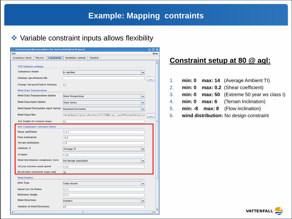
Example: Mapping contraints
Variable constraint inputs allows flexibility
Constraint setup at 80 @ agl:
1. min: 0 max: 14 (Average Ambient TI)
2. min: 0 max: 0.2 (Shear coefficient)
3. min: 0 max: 50 (Extreme 50 year ws class I)
4. min: 0 max: 6 (Terrain Inclination)
5. min: -8 max: 8 (Flow inclination)
6. wind distribution: No design constraint

Example: Mapping contraints
COMBINED CONSTRAINTS
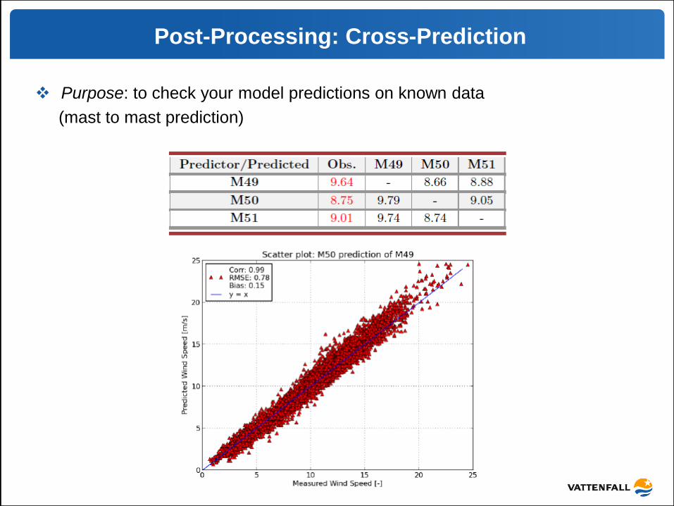
Post-Processing: Cross-Prediction
Purpose: to check your model predictions on known data
(mast to mast prediction)

Post-Processing: Cross-Prediction
Sectorwise cross-predictions for wind speed and ambient TI
Wind standard deviation extrapolated using the Reynolds number independent
assumption

Post-Processing: Cross-Prediction
Wind climatology at every WT position
Sectorwise shear coefficient and Turbulence intensity at 10 m/s tables
highlighting problematic sectors

Report generation tool
Results from site prospecting / Cross-prediction / Energy assessment
are sumarized in .pdf report.

CFD experiences in Sweden
Common practice is to run: CFD + WAsP
Most of the projects are hilly and forested
Site classification (2 + 3, hilly and forest)
• Main difference forest treatment
a) Forest heights seen by CFD at site X b) Wasp only sees roughness
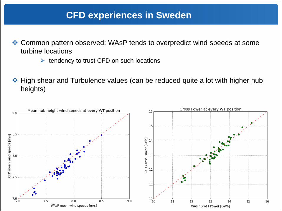
CFD experiences in Sweden
Common pattern observed: WAsP tends to overpredict wind speeds at some
turbine locations
tendency to trust CFD on such locations
High shear and Turbulence values (can be reduced quite a lot with higher hub
heights)

Modelling atmospheric stability
In-house R&D project was set to investigate the potential added value
of modelling atmospheric stability using the available Ansys-CFX windmodeller
stability model.
transient model solving an extra model equation on Enthalpy
buoyancy term is present in the momentum equations
Due to the lack of 2-height temperature measurement met-masts in our assets
it has been difficult to arrive to statistically meaningful conclusions
Modelling challenges:
Not a steady-state flow
spurious gravity waves difficult to handle
longer simulation times
convergence issues (unstable flows especially)
Risk of garbage-in - garbage-out
Non-Reynolds dependant flow >>> several simulations per wind sector
(time consuming)

THANK YOU FOR YOUR ATTENTION !