wil 19020 e 02-1600s-web
TRANSCRIPT

HighPressure
H25
WIL-11180-E-02Replaces EOM Rhino 1600S 8/03
EOME n g i n e e r i n g O p e r a t i o n &M a i n t e n a n c eAdvanced™ Series METAL Pumps
A d v a n c e y o u r p r o c e s s
TABLE OF CONTENTSPAGE #
SECTION 1 — PUMP DESIGNATION SYSTEM ......................................... 1
SECTION 2 — HOW IT WORKS (PUMP) .......................................................... 2
SECTION 3 — CAUTIONS — READ FIRST! ................................................... 3
SECTION 4 — DIMENSIONAL DRAWING ....................................................... 4
SECTION 5 — PERFORMANCE CURVE .......................................................... 5
SECTION 6 — INSTALLATION & OPERATIONA. Installation........................................................................................................................... 6
B. Installation — Wetted Path................................................................................................. 7
C. Installation — Remote Solenoid ......................................................................................... 7
D. Operation & Maintenance................................................................................................... 8
E. Installation — Electrical Connections................................................................................. 8
F. Troubleshooting .................................................................................................................. 9
SECTION 7 — DIRECTIONS FOR DISASSEMBLY/REASSEMBLYA. Model H25/1600S Wetted Path Disassembly .................................................................... 10
B. Reassembly Hints & Tips, Torque Specs ........................................................................... 13
SECTION 8 — EXPLODED VIEW/PARTS LISTING .................................. 14
SECTION 9 — ELECTRICAL INFORMATION ................................................ 16
Cla
ss
I &II Ozone
Depleting Substanc
esNON
USEU.S. Clean Air Act
Amendments of 1990

MODEL H25/1600S MATERIAL CODES
SECTION 1
WILDEN PUMP DESIGNATION SYSTEM
MODELH25 = 6 mm (¹/⁴") CONNECTIONS
MAX. DISCHARGE PRESSURE1600 = 110.3 BAR (1,600 PSIG)
PUMP TYPES = SIMPLEX
LIQUID CHAMBERA = ALUMINUM
CHAMBER COVERA = ALUMINUM
VALVE SEATSS = STAINLESS STEEL
VALVE SEAT O-RINGSBN = BUNA-N
SPECIALTY CODES150 = 24V DC COIL151 = 24V AC COIL153 = 24V AC, NEMA 7 COIL154 = 24V DC, NEMA 7 COIL155 = 110V AC COIL156 = 110V AC, NEMA 7 COIL157 = INTERNATIONAL 24V DC COIL** International 24V DC Coil is explosion proof per PTB File#EX-91.C.2027
AIR VALVEA = ALUMINUM
LIQUID PISTON SEALSPU = POLYURETHANE
VALVE BALLSSS = STAINLESS STEEL

SECTION 2
H25/1600S — HOW IT WORKSThe Wilden piston pump is an air-operated, positive displacement, self-priming pump. These drawings show the flow patternthrough the pump upon its initial stroke. It is assumed the pump has no fluid in it prior to its initial stroke.
FIGURE 1: When air pressure is supplied to the pump andthe solenoid coil is unpowered, the air valve directs air pres-sure to the front side (A) of the power/liquid piston throughthe tubing connected to the air valve. At this time, thepower/liquid piston is on its suction stroke. At the same time,the air on the back side (B) of the power/liquid piston is beingforced out to atmosphere through the exhaust port locatedtowards the top of the air valve. Movement of thepower/liquid piston away from the liquid chamber creates avacuum within the wetted portion of the pump, atmosphericpressure on the inlet fluid forces the inlet valve ball off its seatand allows the fluid being pumped to fill the liquid chamber.
FIGURE 2: When the solenoid is powered, the air valve redi-rects pressurized air to the back side (B) of the power/liquidpiston which forces the power/liquid piston to move towardsthe liquid chamber. The movement of the power/liquid pistontowards the liquid chamber moves the discharge valve balloff its seat and allows the fluid being pumped to exit thedischarge port. At this same time, the air on the front side (A)of the power/liquid piston is being forced out to atmospherethrough the exhaust port located towards the bottom of theair valve. This constitutes one complete pumping cycle. Thepump may take several cycles to completely prime depend-ing on the conditions of the application.
OUTLET
CLOSED
OPEN
INLET
A
A
B
B
AIR
AIR
CLOSED
OPEN
INLET
OUTLET
A
A
B
B
AIR
AIR
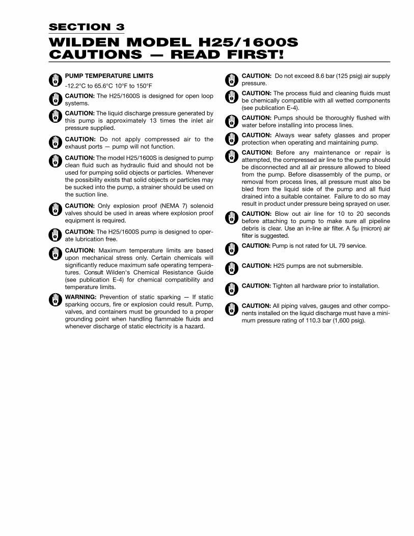
SECTION 3
WILDEN MODEL H25/1600SCAUTIONS — READ FIRST!
PUMP TEMPERATURE LIMITS
-12.2°C to 65.6°C 10°F to 150°F
CAUTION: The H25/1600S is designed for open loopsystems.
CAUTION: The liquid discharge pressure generated bythis pump is approximately 13 times the inlet airpressure supplied.
CAUTION: Do not apply compressed air to theexhaust ports — pump will not function.
CAUTION: The model H25/1600S is designed to pumpclean fluid such as hydraulic fluid and should not beused for pumping solid objects or particles. Wheneverthe possibility exists that solid objects or particles maybe sucked into the pump, a strainer should be used onthe suction line.
CAUTION: Only explosion proof (NEMA 7) solenoidvalves should be used in areas where explosion proofequipment is required.
CAUTION: The H25/1600S pump is designed to oper-ate lubrication free.
CAUTION: Maximum temperature limits are basedupon mechanical stress only. Certain chemicals willsignificantly reduce maximum safe operating tempera-tures. Consult Wilden's Chemical Resistance Guide(see publication E-4) for chemical compatibility andtemperature limits.
WARNING: Prevention of static sparking — If staticsparking occurs, fire or explosion could result. Pump,valves, and containers must be grounded to a propergrounding point when handling flammable fluids andwhenever discharge of static electricity is a hazard.
CAUTION: Do not exceed 8.6 bar (125 psig) air supplypressure.
CAUTION: The process fluid and cleaning fluids mustbe chemically compatible with all wetted components(see publication E-4).
CAUTION: Pumps should be thoroughly flushed withwater before installing into process lines.
CAUTION: Always wear safety glasses and properprotection when operating and maintaining pump.
CAUTION: Before any maintenance or repair isattempted, the compressed air line to the pump shouldbe disconnected and all air pressure allowed to bleedfrom the pump. Before disassembly of the pump, orremoval from process lines, all pressure must also bebled from the liquid side of the pump and all fluiddrained into a suitable container. Failure to do so mayresult in product under pressure being sprayed on user.
CAUTION: Blow out air line for 10 to 20 secondsbefore attaching to pump to make sure all pipelinedebris is clear. Use an in-line air filter. A 5µ (micron) airfilter is suggested.
CAUTION: Pump is not rated for UL 79 service.
CAUTION: H25 pumps are not submersible.
CAUTION: Tighten all hardware prior to installation.
CAUTION: All piping valves, gauges and other compo-nents installed on the liquid discharge must have a mini-mum pressure rating of 110.3 bar (1,600 psig).

A
C
E
H
J
K
D
F
G
B
DIMENSIONS – H25/1600S
ITEM METRIC (mm) STANDARD (inch)A 188 7.4B 86 3.4C 20 0.8D 236 9.3E 183 7.2F 28 1.1G 188 7.4H 13 0.5J 150 5.9K 10 0.4
SECTION 4
DIMENSIONAL DRAWINGWILDEN MODEL H25/1600S PUMP
6 mm (1/4") FNPT DISCHARGE
10 mm (3/8") FNPT AIR INLET
13 mm (1/2") FNPT INLET
Top View
Side View
Bottom View
End View

SECTION 5
PERFORMANCE CURVEWILDEN H25/1600S PUMPHeight ....................................236 mm (9.3")Width .....................................188 mm (7.4")Depth .....................................183 mm (7.2")Ship Weight ..............Aluminum 7 kg (16 lbs)Air Inlet......................................10 mm (³⁄₈")Inlet ...........................................13 mm (¹⁄²")Outlet ..........................................6 mm (¹⁄⁴")Suction Lift .........................7.8 m Dry (25.5')
9.2 m Wet (30.1')Max. Flow Rate .................4.1 lpm (1.1 gpm)
Example: To pump 2.6 lpm (0.7 gpm) againsta discharge head of 20.7 bar (300 psig)requires 4.1 bar (60 psig) and 20.4 Nm3/h(12 scfm) air consumption (see dot on chart).
Caution: Do not exceed 8.6 bar (125 psig) airsupply pressure.
Flow rates indicated on chart were determined by pumping water.

SECTION 6A
SUGGESTED INSTALLATIONThe H25/1600S has a 13 mm (₁⁄₂") inlet and 6 mm (₁⁄₄") outlet and is designed for discharge pressure to 110.3bar (1600 psig). Refer to Section 5 for performance charac-teristics. The H25/1600S pump is manufactured withwetted parts of aluminum. The H25/1600S is available withan aluminum air valve.
The suction pipe size should be at least 13 mm (₁⁄₂")diameter or larger if highly viscous material is beingpumped. The suction hose must be non-collapsible, rein-forced type as the H25/1600S is capable of pulling a highvacuum. Discharge piping should be at least 6 mm (₁⁄₄") andmust have a minimum pressure rating of 110.3 bar (1,600psig); larger diameter can be used to reduce friction losses.It is critical that all fittings and connections are airtight or areduction of pump suction capability will result.
All wiring used to operate the pump should be placed andconnected according to all applicable electrical codes. It isimportant that the wiring be of adequate gauge to carry thecurrent required to operate the pump. In addition, it isnecessary that the electrical power supply be large enoughto supply the current required to operate the pump. Wiringshould be above ground level if possible (in case of fluidspill or leakage), and all wiring and connections whichcould become wet or damp should be made watertight.
INSTALLATION: Months of careful planning, study, andselection efforts can result in unsatisfactory pump perfor-mance if installation details are left to chance.
Premature failure and long term dissatisfaction can beavoided if reasonable care is exercised throughout theinstallation process.
LOCATION: Noise, safety, and other logistical factorsusually dictate where equipment will be situated on theproduction floor. Multiple installations with conflictingrequirements can result in congestion of utility areas, leav-ing few choices for additional pumps.
Within the framework of these and other existing conditions,every pump should be located in such a way that five keyfactors are balanced against each other to maximumadvantage.
ACCESS: First of all, the location should be accessible. Ifit’s easy to reach the pump, maintenance personnel willhave an easier time carrying out routine inspections andadjustments. Should major repairs become necessary, easeof access can play a key role in speeding the repair processand reducing total downtime.
AIR SUPPLY: Every pump location should have an air linelarge enough to supply the volume of air necessary toachieve the desired pumping rate (see Section 5). Use airpressure up to a maximum of 8.6 bar (125 psig) dependingon pumping requirements.
For best results, the pumps should use a 5µ (micron) airfilter, needle valve and regulator. The use of an air filterbefore the pump will ensure that the majority of any pipelinecontaminants will be eliminated.
ELEVATION: Selecting a site that is well within the pump’sdynamic lift capability will assure that loss-of-prime trou-bles will be eliminated. In addition, pump efficiency can beadversely affected if proper attention is not given to sitelocation.
PIPING: Final determination of the pump site should not bemade until the piping problems of each possible locationhave been evaluated. The impact of current and futureinstallations should be considered ahead of time to makesure that inadvertent restrictions are not created for anyremaining sites.
The best choice possible will be a site involving the short-est and straightest hook-up of suction and dischargepiping. Unnecessary elbows, bends, and fittings should beavoided. Pipe sizes should be selected so as to keep fric-tion losses within practical limits. All piping should besupported independently of the pump. In addition, thepiping should be aligned so as to avoid placing stress onthe pump fittings.
If the pump is to be bolted down to a solid location, amounting pad placed between the pump and the founda-tion will assist in minimizing pump vibration.
If the pump is to be used in a self-priming application, besure that all connections are airtight and that the suction liftis within the model’s ability.
When pumps are installed in applications involving floodedsuction or suction head pressures, a gate valve should beinstalled in the suction line to permit closing of the line forpump service.
THE MODEL H25/1600S SHOULD NOT BE USED WITHMEDIA CONTAINING SOLIDS. WHENEVER THE POSSIBIL-ITY EXISTS THAT SOLID OBJECTS MAY BE SUCKED INTOTHE PUMP, A STRAINER SHOULD BE USED ON THESUCTION LINE.
CAUTION: THE H25/1600S PUMP IS DESIGNED FOROPEN LOOP SYSTEMS.
CAUTION: DO NOT EXCEED 8.6 BAR (125 PSIG) AIRSUPPLY PRESSURE.
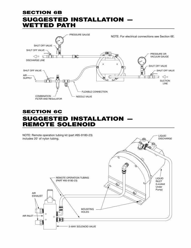
REMOTE OPERATION TUBING(PART #95-9180-23)
MOUNTINGHOLES
AIREXHAUST
AIR INLET
5-WAY SOLENOID VALVE
LIQUIDINLET(LocatedUnderPump)
LIQUIDDISCHARGE
NOTE: Remote operation tubing kit (part #95-9180-23)includes 20' of nylon tubing.
NOTE: For electrical connections see Section 6E.
SECTION 6B
SUGGESTED INSTALLATION — WETTED PATH
SECTION 6C
SUGGESTED INSTALLATION — REMOTE SOLENOID
PRESSURE GAUGE
SHUT OFF VALVE
SHUT OFF VALVE
SHUT OFF VALVE
DISCHARGE LINE
AIRSUPPLY
COMBINATION FILTER AND REGULATOR
NEEDLE VALVE
FLEXIBLE CONNECTION
SUCTIONLINE
SHUT OFF VALVE
SHUT OFF VALVE
PRESSURE ORVACUUM GAUGE

COMMON CONNECTION
FLICKER MODE RELAY OR BATCH CONTROLLER
SWITCHED (CONTROL)CONNECTION
GROUNDCONNECTION
SECTION 6D
SUGGESTED OPERATION ANDMAINTENANCE INSTRUCTIONSOPERATION: The H25/1600S is pre-lubricated and does notrequire in-line lubrication. Additional lubrication will notdamage the pump, however if the pump is heavily lubricatedby an external source, the pump operation may be affected.It may need to be disassembled and re-lubricated asdescribed in the ASSEMBLY/DISASSEMBLY INSTRUCTIONS.
Pump discharge rate can be controlled by limiting the volumeand/or pressure of the air supply to the pump (preferredmethod). A regulator is used to control air pressure while aneedle valve is used to control volume. Pump discharge ratecan also be controlled by throttling the pump discharge bypartially closing a valve in the discharge line of the pump.This action increases friction loss which reduces flow rate.(See Section 5.) This is useful when the need exists to controlthe pump from a remote location. When the pump dischargepressure equals or exceeds approximately 13 times the airinlet pressure, the pump will stop; no bypass or pressurerelief valve is needed, and pump damage will not occur. Thepump has reached a “deadhead” situation and can berestarted by reducing the fluid discharge pressure or increas-ing the air inlet pressure. The Wilden R.025/1600S pumpruns solely on compressed air and generates little heat,therefore your process fluid temperature will not be affected.
MAINTENANCE AND INSPECTIONS: Since each applica-tion is unique, maintenance schedules may be different forevery pump. Frequency of use, line pressure, viscosity andabrasiveness of process fluid all affect the parts life of aWilden pump. Periodic inspections have been found tooffer the best means for preventing unscheduled pumpdowntime. Personnel familiar with the pump’s constructionand service should be informed of any abnormalities thatare detected during operation.
RECORDS: When service is required, a record should bemade of all necessary repairs and replacements. Over aperiod of time, such records can become a valuable tool forpredicting and preventing future maintenance problemsand unscheduled downtime. In addition, accurate recordsmake it possible to identify pumps that are poorly suited totheir applications.
SECTION 6E
INSTALLATION—ELECTRICAL CONNECTIONS When the solenoid is unpowered, the back side of the powerpiston is pressurized with air and the power/liquid pistonassembly is in its full discharge stroke position. When electricpower is applied, the solenoid valve shifts and the pressureon the back side of the power piston is exhausted while thefront side of the power piston is pressurized with air. By alter-nately applying and removing power, the solenoid operatedpump reciprocates.
The speed of the pump is controlled electrically. Since eachstroke is controlled by an electrical signal, the pump is idealfor batching and other electrically controlled dispensingapplications.
Although the speed of the pump is controlled electrically,the air pressure is important. Air pressure displaces the fluid,and if the pressure is insufficient to complete the physicalstroke before an electronic impulse signals the pump toshift, the shift will not be completed, and the displacementper stroke will be reduced. This does not harm the unit inany way, but it may cause inaccuracy when attempting tobatch specific quantities with high precision if this effect isnot taken into account.
There are three coil voltage options available. One coil allowsfor 24V DC operation. The second coil option allows foroperation with either 12V DC or 24V AC at 50 or 60 Hz andthe third coil option allows for 110V AC operation.
ELECTRICAL CONNECTIONS

SECTION 6F
TROUBLESHOOTINGPump will not run or runs slowly.1. Check for pressurized air at the inlet.2. Check air inlet and filter for debris.3. Connect a test lamp to the two wires which run to pump
and ensure that the lamp cycles on and off.4. Make sure that the air valve manual override (small red
knob on front of valve) is switched to the "0" position.5. Check pilot pressure vent at the top of the operator/coil
assembly to ensure that it is not clogged.6. Check for a worn out air valve. If air continually blows
out the exhaust in very large quantities, the air valveseals may be worn beyond their ability to function. Inthis case, the valve must be replaced.NOTE: It is possible that a malfunctioning valve can besaved by completely disassembling the valve, cleaningand re-lubricating for proper operation.
7. Disassemble pump and check for obstructions in the airpassageways or objects which would obstruct themovement of internal parts.
8. Remove shipping plugs.
Pump runs but little or no product flows.1. Check that the discharge isolation valve is not closed.2. Check that the electric signal is slow enough that the
pump is able to complete each physical stroke before itis signaled to change direction. The time required tocomplete the stroke is determined by a variety of factorswhich include fluid viscosity and head pressure.
3. Check for pump cavitation; slow pump speed down tomatch the thickness of the material being pumped.
4. Check for sticking ball and check valves. If the materialbeing pumped is not compatible with the pump elas-tomers, swelling may occur. Replace seals with theproper elastomers.
5. Check to make sure that all suction connections are airtight, and that the fasteners are properly tightened.
Air bubbles in pump discharge.1. Check for damaged or worn liquid piston seal.2. Check tightness of fasteners, and the integrity of the O-
rings, especially at intake manifold plate.
Product comes out air exhaust.1. Check for damaged or worn power piston seal.2. Check tightness of liquid piston to liquid piston screw.
Solenoid buzzes or solenoid burnout.1. Incorrect voltage, faulty or dirty solenoid.
Solenoid valve fails to shift electrically but shifts withmanual override.1. Incorrect voltage, defective coil or wiring.
Valve shifts but fails to return.1. Broken spring, mechanical binding.
Excessive leaking from air valve vent.1. Worn seals in air valve.

SECTION 7A
MODEL H25/1600S PUMPDIRECTIONS FOR DISASSEMBLY/REASSEMBLY
DISASSEMBLY:
Step 1. Figure 1
Before starting disassembly, mark a line from the liquidchamber to the chamber cover. This line will assist in properalignment during reassembly.
CAUTION: Before any maintenance or repair is attempted, thecompressed air line to the pump should be disconnected andall air pressure allowed to bleed from the pump. Disconnect allintake, discharge, and air lines. Drain the pump by turning itupside down and allowing any fluid to flow into a suitablecontainer. Be aware of the hazardous effects associated withcontact with your process fluid.
The H25/1600S metal pump has a 13 mm (₁⁄₂") inlet and 6 mm(₁⁄₄") outlet and is designed for flows up to 4.1 lpm (1.1 gpm).The H25/1600S is available with aluminum wetted parts, cham-ber cover and air valve.
TOOLS REQUIRED:6 mm (¹⁄₄") Hex Head Wrench5 mm (³⁄¹⁶") Hex Head Wrench 14 mm (⁹⁄¹⁶") WrenchO-ring PickAir Nozzle (rubber dipped)Adjustable WrenchVise equipped w/soft jaws(such as plywood, plastic or other suitable material)
Step 2. Figure 2
Using a 14mm (₉⁄¹⁶") wrench, loosenfastener connecting nylon tube to liquidchamber by turning counter-clockwise.
Step 3. Figure 3
Disconnect nylon tube by pulling tubeaway from brass elbow.
Step 4. Figure 4
Using a 14mm (₉⁄¹⁶") wrench, loosenfastener connecting nylon tube tochamber cover by turning counter-clockwise.

Step 5. Figure 5
After disconnecting nylon tube, lift airvalve away from the pump.
Step 6. Figure 6
Using a 6mm (¹⁄⁴") hex head wrench,remove the liquid chamber bolts thatconnect the chamber cover to the liquidchamber.
Step 7. Figure 7
Lift the chamber plate away to exposethe chamber plate O-ring and the powerpiston. Inspect chamber plate O-ring fornicks, gouges, chemical attack orabrasive wear. Replace worn parts withgenuine Wilden parts for reliableperformance.
Step 8. Figure 8
To remove the power piston from the liquidchamber, first place the liquid chamberonto a table or sturdy flat surface. Next,with the liquid chamber resting on thebolted flange, apply 1.0 bar (15 psig) of airpressure, via a rubber tipped air nozzle,into the brass elbow located at the sameside as the pump discharge port.CAUTION: The power piston may comeout of the liquid chamber with consid-erable force. Altering the disassemblymethod above is not recommended andmay cause physical harm.
Step 9. Figure 9
The air pressure will force the powerpiston away from the liquid chamber toallow for easy removal.
Step 10. Figure 10
Using a 5mm (³⁄¹⁶") hex head wrench,remove the liquid piston from the powerpiston by turning the power pistonscrew counter-clockwise.
Chamber Plate O-ring
Power Piston
PowerPiston

Step 11. Figure 11
Lift the liquid piston away from thepower piston.
Step 12. Figure 12
Inspect the power piston O-rings for nicks,gouges, chemical attack or abrasive wear.Replace worn parts if necessary.
Step 13. Figure 13
Inspect the liquid piston bore cup sealsfor nicks, gouges, chemical attack orabrasive wear.
Step 14. Figure 14
If the cup seals are damaged and needto be replaced, install new cup seals.When installing new cup seals, cup sideof both seals should face away from one-another. The cup on the inner cup sealshould face towards the bolt flange onthe liquid chamber. The cup on the outercup seal should face towards the valveball area of the liquid chamber.
Step 15. Figure 15
To inspect or replace the dischargemanifold O-ring, valve seat O-ring, valveseat, valve ball and ball cage, firstremove the combo manifold plate locatedat the top of the liquid chamber. To inspect or replace the inlet manifoldO-ring, valve seat O-ring, valve seat,valve ball and ball cage, repeat process.
Step 16. Figure 16
With the combo manifold plate removed,the manifold O-ring, valve seat O-ring,valve seat, valve ball and ball cage canbe inspected for nicks, gouges, chemicalattack or abrasive wear. Repeat processat inlet manifold plate. Replace wornparts with genuine Wilden parts forreliable performance.
InnerCup Seal
Cup areaof seal
OuterCup Seal

ASSEMBLY:Upon performing applicable maintenance to the air distrib-ution system, the pump can now be reassembled. Pleaserefer to the disassembly instructions for photos and partsplacement. To reassemble the pump, follow the disassem-bly instructions in reverse order. Please find the applicabletorque specifications on this page. The following tips willassist in the assembly process.
• To ease in the reassembly process, mark a line from theliquid chamber to the chamber cover. This will assistwith proper alignment during reassembly.
• Apply a small amount of Loctite® 242 to thepower/liquid bolt threads.
• If air continually blows out the exhaust in very largequantities, it is possible that it may be saved bycompletely disassembling the valve, cleaning allcomponents and re-lubricating the valve.
• If pump stops running or begins to run slowly, inspectreturn spring located at the bottom portion of air valvefor damage.
• When installing inlet air or exhaust connections, usecorrect porting on the air valve or pump will not run.(See example below for correct connections).
Description of Part TorqueInlet Manifold Plate 13.5 N•m [10 ft.-lbs.]Combo Manifold Plate 13.5 N•m [10 ft.-lbs.]Liquid Chamber 13.5 N•m [10 ft.-lbs.]
MAXIMUM TORQUE SPECIFICATIONS
SECTION 7B
REASSEMBLY HINTS & TIPS
Air ExhaustAir Inlet

5
6
2
3
4
1
13
1514
7
1110
9
2221201918
16
23
12
8
17
24
24
SECTION 8
EXPLODED VIEW/PARTS LISTING
H25/1600S

H25/1600S PumpItem Qty. per
# Part Description Pump Part Number1 Solenoid Valve Assy (Includes Items 2-5) 1 95-2000-99-1502 Main Valve Body (Includes item 3) 1 95-2000-01-1503 Solenoid Operator 1 00-2120-994 Coil 1 00-2110-99-1505 Terminal Connector (NEMA 4 Only) 1 00-2130-996 3/8" Muffler 2 95-3240-077 Tube & Fitting Assy. 1 95-9230-998 Liquid Chamber 1 95-5000-019 Liquid Piston 1 95-3723-09
10 Power Piston, Simplex 1 95-3722-0111 Screw, 5/16-18 X 3/4" 1 95-6222-0812 Piston Seal Kit 1 95-9210-9913 Chamber Cover 1 95-3001-0114 Support Foot 1 95-5541-0115 Screw, SHC, 5/16-18 X 1/2" 2 08-6031-08-60R16 Inlet Manifold Plate 1 95-5080-0117 Combo Manifold Plate 1 95-5050-0118 Manifold O-ring 2 04-2390-5219 Valve Seat 2 95-1120-0320 Valve Seat O-ring 2 00-2390-52-70021 Valve Ball 2 95-1080-0322 Ball Cage 2 95-5350-0323 Screw, SHC, 5/16-18 X 1-3/4" 4 95-6010-0824 Screw, SHC, 5/16-18 X 1" 10 95-6011-08
Remote Operation tubing (Not Showing)* 1 95-9180-23
*Not included with purchase of pump.All boldface items are primary wear parts.
Specialty Code Part Number Description150 95-2000-99-150 24V DC Valve Assembly
151 95-2000-99-151 24V AC / 12V DC Valve Assembly
153 95-2000-99-153 24V AC / 12V DC Valve Assembly (NEMA 7)
154 95-2000-99-154 24V DC Valve Assembly (NEMA 7)
155 95-2000-99-155 110V AC Valve Assembly
156 95-2000-99-156 110V AC Valve Assembly (NEMA 7)
157 95-2000-99-157 International 24V DC Valve Assembly1
Item 1 Valve Assembly Options(CONSISTS OF VALVE BODY, COIL, OPERATOR AND CONNECTOR)
Item 2 Main Valve Body OptionsPart Number Description95-2000-01-150 Main Valve Body
95-2000-01-154 Main Valve Body (NEMA 7)
Item 3 & 4 Coil & Operator OptionsSpecialty Code Part Number Description Solenoid Operator P/N
150 00-2110-99-150 24V DC Coil 00-2120-99
151 00-2110-99-151 24V AC / 12V DC Coil 00-2120-99
153 00-2110-99-153 24V AC / 12V DC Coil (NEMA 7) 00-2121-99
154 00-2110-99-154 24V DC Coil (NEMA 7) 00-2121-99
155 00-2110-99-155 110V AC Coil 00-2120-99
156 00-2110-99-156 110V AC Coil (NEMA 7) 00-2121-99
157 00-2110-99-157 International 24V DC Coil1 00-2120-99
1Meet European standards and regulations; CENELEC/PTB file # EX-9.C.2027.

SECTION 9
ELECTRICAL INFORMATIONNEMA 4 / UL / CSA
Voltage ±10% Current (A)AC AC
DC Power (W) DC ResistivityPart Number 60 Hz 50 Hz ±10% Inrush Holding ( )00-2110-99-150 24 48 44 4.8 .20 .20 .20 12100-2110-99-151 12 24 22 4.8 .40 .40 .40 3200-2110-99-155 60 120 110 4.8 .08 .08 .06 840
NEMA 7 / UL / CSAVoltage ±10% Current (A)
AC ACDC Power (W) DC Resistivity
Part Number 60 Hz 50 Hz ±10% Inrush Holding ( )00-2110-99-153 12 24 22 7 .60 .55 .32 1900-2110-99-154 24 48 44 7 .30 .30 .18 7500-2110-99-156 60 120 110 7 .12 .13 .06 475
INTERNATIONAL EXPLOSION PROOF / CENELEC / PTB FILE # EX-91.C.2027Current (A)
DC Voltage ±10% Power (W) ResistivityPart Number ±10% Inrush Holding ( )00-2110-99-157 24 3.3 .135 .135 177

TT5178