wide-area robust h control with pole placement for …cdn.intechweb.org/pdfs/23883.pdf ·...
TRANSCRIPT

15
Wide-Area Robust H2/H∞ Control with
Pole Placement for Damping Inter-Area Oscillation of Power System
Chen He1 and Bai Hong2
1State Power Economic Research Institute, State Grid Corporation of China 2China Electric Power Research Institute
China
1. Introduction
The damping of inter-area oscillations is an important problem in electric power systems
(Klein et al., 1991; Kundur, 1994; Rogers, 2000). Especially in China, the practices of
nationwide interconnection and ultra high voltage (UHV) transmission are carrying on and
under broad researches (Zhou et al., 2010), bulk power will be transferred through very long
distance in near future from the viewpoints of economical transmission and requirement of
allocation of insufficient resources. The potential threat of inter-area oscillations will
increase with these developments. If inter-area oscillations happened, restrictions would
have to be placed on the transferred power. So procedures and equipments of providing
adequate damping to inter-area oscillations become mandatory.
Conventional method coping with oscillations is by using power system stabilizer (PSS) that
provides supplementary control through the excitation system (Kundur, 1994; Rogers, 2000;
Larsen et al., 1981), or utilizing supplementary control of flexible AC transmission systems
(FACTS) devices (Farsangi et al., 2003; Pal et al., 2001; Chaudhuri et al., 2003, 2004).
Decentralized construction is often adopted by these controllers. But for inter-area
oscillations, conventional decentralized control may not work so well since they have not
observability of system level. Maximum observability for particular modes can be obtained
from the remote signals or from the combination of remote and local signals (Chaudhuri et
al., 2004; Snyder, et al., 1998; Kamwa et al., 2001). Phasor measurement units (PMUs)-based
wide-area measurement system (WAMS) (Phadke, 1993) can provide system level
observability and controllability and make so-called wide-area damping control practical.
On the other hand, power system exists in a dynamic balance, its operating condition always changes with the variations of generations or load patterns, as well as changes of system topology, etc. From control theory point of view, these changes can be called uncertainty. Conventional control methods can not systemically consider these uncertainties, and often need tuning or coordination. Therefore, so-called robust models are derived to take these uncertainties into account at the controller design stage (Doyle et al., 1989; Zhou et al., 1998). Then the robust control is applied on these models to realize both disturbance attenuation and stability enhancement.
www.intechopen.com

Challenges and Paradigms in Applied Robust Control
332
In robust control theory, H2 performance and H∞ performance are two important specifications. H∞ performance is convenient to enforce robustness to model uncertainty, H2 performance is useful to handle stochastic aspects such as measurement noise and capture the control cost. In time-domain aspects, satisfactory time response and closed-loop damping can often be achieved by enforcing the closed-loop poles into a pre-determined subregion of the left-half plane (Chilali et al., 1996). Combining there requirements to form so-called mixed H2/H∞ design with pole placement constrains allows for more flexible and accurate specification of closed-loop behavior. In recent years, linear matrix inequalities (LMIs) technique is often considered for this kind of multi-objective synthesis (Chilali et al., 1996; Boyd et al., 1994; Scherer et al., 1997, 2005). LMIs reflect constraints rather than optimality, compared with Riccati equations-based method (Doyle et al., 1989 ; Zhou et al., 1998), LMIs provide more flexibility for combining various design objectives in a numerically tractable manner, and can even cope with those problems to which analytical solution is out of question. Besides, LMIs can be solved by sophisticated interior-point algorithms (Nesterov et al., 1994). In this chapter, the wide-area measurement technique and robust control theory are combined together to design a wide-area robust damping controller (WRC for short) to cope with inter-area oscillation of power system. Both local and PMU-provided remote signals, which are selected by analysis results based on participation phasor and residue, are utilized as feedback inputs of the controller. Mixed H2/H∞ output-feedback control design with pole placement is carried out. The feedback gain matrix is obtained through solving a family of LMIs. The design objective is to improve system damping of inter-area oscillations despite of the model changes which are caused mainly by load changes. Computer simulations on a 4-generator benchmark system model are carried out to illustrate the effectiveness and robustness of the designed controller, and the results are compared with the conventional PSS. The rest of this chapter is organized as follows: In Section 2 a mixed H2/H∞ output-feedback control with pole placement design based on the mixed-sensitivity formulation is presented. The transformation into numerically tractable LMIs is provided in Section 3. Section 4 gives the benchmark power system model and carries out modal analyses. The synthesis procedures of wide-area robust damping controller as well as the computer simulations are presented in Section 5. The concluding remarks are provided in Section 6.
2. H2/H∞ Control with pole placement constrain
2.1 H∞ mixed-sensitivity control
Oscillations in power systems are caused by variation of loads, action of voltage regulator due to fault, etc. For a damping controller these changes can be considered as disturbances on output y (Chaudhuri et al., 2003, 2004), the primary function of the controller is to minimize the impact of these disturbances on power system. The output disturbance rejection problem can be depicted in the standard mixed-sensitivity (S/KS) framework, as shown in Fig. 1, where sensitivity function S(s)=(I-G(s)K(s))-1. An implied transformation existing in this framework is from the perturbation of model uncertainties (e.g. system load changes) to the exogenous disturbance. Consider additive model uncertainty as shown in Fig. 2, The transfer function from perturbation d to controller output u, Tud, equals K(s)S(s). By virtue of small gain theory, ǁTud∆(s)ǁ∞<1 if and only if ǁW2(s)Tudǁ∞<1 with a frequency-depended weighting function ∣W2(s)∣>∣∆(s)∣. So a system with additive model uncertain perturbation (Fig. 2) can be transformed into a disturbance
www.intechopen.com

Wide-Area Robust H2/H∞ Control with Pole Placement for Damping Inter-Area Oscillation of Power System
333
rejection problem (Fig. 1) if the weighted H∞ norm of transfer function form d to u is small than 1, and the weighting function W2(s) is the profile of model uncertainty.
Fig. 1. Mixed sensitivity output disturbance rejection
Fig. 2. System with additive model uncertainty
The design objective of standard mixed-sensitivity design problem, shown in Fig. 1, is to
find a controller K(s) from the set of internally stabilizing controller such that
1
2
( ) ( )min 1
( ) ( ) ( )K
s s
s s s
W S
W K S (1)
In (1), the upper inequality is the constraint on nominal performance, ensuring disturbance rejection, the lower inequality is to handle the robustness issues as well as limit the control effort. Knowing that the transfer function from d to y, Tyd, equals S(s). So condition (1) is equivalent to
1
2
( )min 1
( )
yd
Kud
s
s
W T
W T (2)
or
min 1dK
z T
(3)
The system performance and robustness of controlled system is determined by the proper selection of weighting function W1(s) and W2(s) in (1) or (2). In the standard H∞ control
www.intechopen.com

Challenges and Paradigms in Applied Robust Control
334
design, the weighting function W1(s) should be a low-pass filter for output disturbance rejection and W2(s) should be a high-pass filter in order to reduce the control effort and to ensure robustness against model uncertainties. But in some cases, there would be a low-pass requirement on W2(s) when the open-loop gain is very high by applying standard lower-pass design, which will result in a conflict in the nature of W2(s) to ensure robustness and minimize control effort (Pal et al., 2001). So the determination of W2(s) should be careful.
2.2 H2 performance for control cost requirement
It is known that the control cost can be more realistically captured through H2 norm, see (Pal et al., 2001) and its reference, this enlightens directly adding H2 performance on controller output u at the design stage, i.e. consider constraint
3 22( ) uds W T (4)
to constrain the control effort and mitigate the burden of selection of W2(s). The weighting function W3(s) is used to compromise between the control effort and the disturbance rejection performance, as shown in Fig. 3.
Fig. 3. Mixed sensitivity output disturbance rejection with other constraint
2.3 Pole placement constraint
H2/H∞ design deals mostly with frequency-domain aspects and provides little control over the transient behavior and closed loop pole location. Satisfactory time response and closed-loop damping can often be achieved by forcing the closed-loop poles into a suitable subregion of the left-half plane, and fast controller dynamics can also be prevented by prohibiting large closed-loop poles. Therefore, besides H∞ and H2 norm constraint, pole placement constraint that confine the poles to a LMI region is also considered. A LMI region S(α, r, θ) is a set of complex number x+jy such that x<-α<0, |x+jy|< r, and
tan(θ)x<-|y|, as shown in Fig. 4. Confining the closed-loop poles to this region can ensure
a minimum decay rate α, and minimum damping ratio ζ=cos(θ), and a maximum undamped natural frequency ωd = rsin(θ). The standard mathematical description of LMI region can be found in (Chilali et al., 1996). The multiple-objective design including H∞/H2 norm and pole placement constrains can be formulated in the LMIs framework and the controller is obtained by solving a family of LMIs.
www.intechopen.com

Wide-Area Robust H2/H∞ Control with Pole Placement for Damping Inter-Area Oscillation of Power System
335
Fig. 4. LMI region S(α, r, θ)
3. Multiple-objective synthesis using LMI method
General mixed H2/H∞ control with pole placement scheme has multi-channel form as shown in Fig. 5. G(s) is a linear time invariant generalized plant, d is vector representing the disturbances or other exogenous input signals, z∞ is the controlled output associated with H∞ performance and z2 is the controlled output associated with H2 performance, u is the control input while y is the measured output.
Fig. 5. Multiple-objective synthesis
The state-space description of above system can be written as
1 2
2 2 21 22
w u
y y
x = Ax + B d B u
z = C x D d D u
z = C x D d D u
y C x D d
(5)
The goal is to compute a output-feedback controller K(s) in the form of
www.intechopen.com

Challenges and Paradigms in Applied Robust Control
336
K K
K K
= A + B y
u C D y
(6)
such that the closed-loop system meets mixed H2/H∞ specifications and pole placement constraint. The closed-loop system can be written as
1 1
2 2 2
c c c c
c c c
c c c
x = A x + B d
z = C x + D d
z = C x + D d
(7)
By virtue of bounded real lemma (Boyd et al., 1994) and Schur’s formula for the determinant of a partitioned matrix, matrix inequality condition (3) is equivalent to the existence of a symmetric matrix X∞>0 such that
1
1
1 1
c c c c
c c
c c
A X + X A B X C
B I D < 0
C X D I
(8)
The closed-loop poles lie in the LMI region (see Fig. 4) S(0, 0, θ) if and only if there exists a symmetric matrix XD such that (Chilali et al., 1996):
) )
) )
sin( )( cos( )(
cos( )( sin( )(
D D D D
D D D D
0AX + X A AX X A
X A AX AX + X A (9)
For H2 performance, ǁW3(s)Tud(s)ǁ2 does not exceed ┛2 if and only if Dc2=0 and there exist two symmetric matrices X2>0 and Q>0 such that
2 2
22 2
2
2 2 2
, Trace
c c c
T
c
c
c
A X + X A B< 0
B I
Q C X0 (Q) <
X C X
(10)
This condition can be deduced from the definition of H2 norm (Chilali et al., 1996 ; Scherer et al., 1997). The multiple-objective synthesis of controller is through solving matrix inequality (8) to (10). But this problem is not jointly convex in the variable and nonlinear, for example nonlinear entry AcX∞ in (8), so they are not numerically tractable. Choosing a single Lyapunov matrix X=X∞=X2=XD and linearizing change of variables can cope with this problem. Choosing a single Lyapunov matrix makes the resulting controller not globally optimal, but is not overly conservative from the practical point of view. The linearizing change of variables is important for multiple-objective output feedback robust synthesis based LMIs. The details can be found in (Chilali et al., 1996 ; Scherer et al., 1997) and the references in them. Finally the result can be obtained as
www.intechopen.com

Wide-Area Robust H2/H∞ Control with Pole Placement for Damping Inter-Area Oscillation of Power System
337
min
s.t. linearized LMIs constraints from (8) to (10)
c x
(11)
This standard LMI problem (Boyd et al., 1994) is readily solved with LMI optimization software. An efficient algorithm for this problem is available in hinfmix() function of the LMI control toolbox for Matlab (Gahinet et al., 1995).
4. A Benchmark system with undamped inter-area oscillation
4.1 Low frequency oscillation in power system One of the major problems in power system operation is low frequency (between 0.1 and 2 Hz) oscillatory instability. Normally no apparent warning can be identified for the occurrence of such kinds of growing oscillations caused by the changes in the system's operating condition or by improper-tuned sustained excitation. The change in electrical torque of a synchronous machine following a perturbation can be resolved as ΔTe=TSΔδ+ TDΔω, where TSΔδ is the component of torque change in phase with the rotor angle perturbation Δ├ and is referred as the synchronizing torque component, TS is the synchronizing torque coefficient. Lack of sufficient synchronizing torque will result in aperiodic drift in rotor angle. TDΔω is the component of torque in phase with the speed deviation Δω and is referred to as the damping torque component, TD is the damping torque coefficient. Lack of sufficient damping torque will result in oscillatory instability. In next section, an example will be used to illustrate the low frequency oscillation of a weak-tied system and the design of a wide-robust damping controller (WRC) to effectively increase the damping ratio of inter-area mode.
4.2 System model and modal analysis A 4-generator benchmark system shown in Fig. 6 is considered. The system parameters is from (Klein et al., 1991) or (Kundur, 1994). However some modifications have been made to facilitate the simulations. The generator G2 is chosen as angular reference to eliminate the undesired zero eigenvalues. Saturation and speed governor are not modeled. Excitation system is chosen by thyristor exciter with a high transient gain. All loads are represented by constant impedance model and complete system parameters are listed in Appendix.
Fig. 6. 4-generator benchmark system model
www.intechopen.com

Challenges and Paradigms in Applied Robust Control
338
After linearization around given operating condition and elimination of algebraic variables, the following state-space representation is obtained.
u
y
x Ax B u
y C x
(12)
where x is state vector; u is input vector, y is output vector; A is the state matrix depending on the system operating conditions, Bu and Cy are input and output matrices, respectively. The number of the original state variables is 28, since generator 2 has been chosen as angular reference, 2 sates are eliminated, so the number of state variables is 26. Following the small-signal theory (Kundur, 1994), the eigenvalues of the test system and corresponding frequencies, damping ratios and electromechanical correlation ratios are calculated. The results are classified in Table 1. It can be found that mode 3 is undamped, which means that the disturbed system can not hold transient stability. The electromechanical correlation ratio in Table 1 is determined by a ratio between summations of eigenvectors relating to rotor angle and rotor speed and summations of other eigenvectors. If the absolute value of one entry (correlation ratio) is much higher than 1, the corresponding mode is considered as electromechanical oscillation.
No. Mode Frequency (Hz) Damping Ratio
(%) Electromechanical Correlation Ratio
1 −0.7412±6.7481 1.0740 0.1092 5.7087
2 −0.7154±6.9988 1.1139 0.1017 5.6918
3 0.0196±3.9141 0.6229 −0.0050 13.2007
Table 1. Results of Modal Analysis
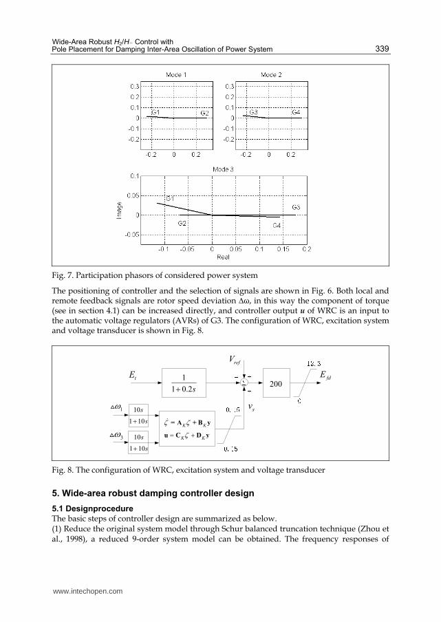
A conception named participation phasor is used to facilitate the positioning of controller and the selection of remote feedback signal. Participation phasor is defined in this easy way: its amplitude is participation factor (Klein et al., 1991; Kundur, 1994) and its phase angle is angle of eigenvector. The analysis results are shown in Fig. 7, in which all vectors are originated from origin (0, 0) and vector arrows are omitted for simplicity. It can be seen that
Mode 1 is a local mode between G1 and G2. The Participation phasor of G3 and G4 are too small to be identified;
Mode 2 is a local mode between G3 and G4. The Participation phasor of G1 and G2 are too small to be identified;
Mode 3 is an inter-area mode between G1, G2 and G3, G4. Wide-area controller is located in G3, which has highest participation factor than others. Even if using local signal only, the controller locating in G3 will have more effects than locating in other generators. Often the residue indicates the sensitivity of eigenvalues to feedback transfer function (Rogers, 2000), that is to say if residue is 0 then feedback control have no effects on controlled system, so residue is used to select suitable remote feedback signal provided by PMU. The residue corresponding to the transfer function between rotor speed output of G1 and excitation system input of G3 is 1.58 (normalized value), while the residue corresponding to the transfer function between rotor speed output of G2 and excitation system input of G3 is 1 (normalized value). So the remote signal is chosen from G1.
www.intechopen.com
Wide-Area Robust H2/H∞ Control with Pole Placement for Damping Inter-Area Oscillation of Power System
339
Fig. 7. Participation phasors of considered power system
The positioning of controller and the selection of signals are shown in Fig. 6. Both local and remote feedback signals are rotor speed deviation ∆ω, in this way the component of torque (see in section 4.1) can be increased directly, and controller output u of WRC is an input to the automatic voltage regulators (AVRs) of G3. The configuration of WRC, excitation system and voltage transducer is shown in Fig. 8.
sv
200fdE1
1 0.2s
refV
K K
K K
= A + B y
u C D y
1
3
tE
10
1 10
s
s10
1 10
s
s
Fig. 8. The configuration of WRC, excitation system and voltage transducer
5. Wide-area robust damping controller design
5.1 Designprocedure
The basic steps of controller design are summarized as below. (1) Reduce the original system model through Schur balanced truncation technique (Zhou et al., 1998), a reduced 9-order system model can be obtained. The frequency responses of
www.intechopen.com

Challenges and Paradigms in Applied Robust Control
340
original and reduced model are compared in Fig. 9, it shows that reduced system has proper approximation to original system within considered frequency range.
Fig. 9. Frequency response of original system model and reduced system model
(2) Formulate the generalized plant in Fig. 5 using the reduced model and the weighting function. The weighting functions are chosen as follows:
1 2 3
80 8.6 4( ) , ( ) , ( ) 1
41 4
ss s s
s s
W W W (13)
The weighting functions are in accordance with the basic requirements of mixed-sensitivity design. W1(s) is a low-pass filter for output disturbance rejection, W2(s) is a high-pass filter for covering the additive model uncertainty, and W3(s) is a weight on H2 performance. (3) Controller design by using the Robust Control Toolbox in Matlab. The solution is numerically sought using suitably defined objectives in the arguments of the hinfmix() function of the Robust Control Toolbox. The LMI region is chosen as a conic sector with inner angle equals 2*acos(0.17) (corresponding damping ratio 17%) and apex at the origin. (4) Controller reduction through Schur balanced truncation technique. A 4-order 2-input 1-output controller is obtained. The state-space representation of the designed controller is
5.4 11.6 4.0 0.1
1.9 14.2 16.1 0.5
9.3 25.2 14.5 0.0
3.3 125.6 10.4 2.7
K
A ,
0.36 6.66
0.36 8.82
0.72 14.94
8.1 25.52
K
B
19.5 25.7 60 2.1K C , 0
0K D .
A washout filter 10s/(10s+1) is added in each feedback channel as shown in Fig. 8. This is a standard practice to prevent the damping controllers from responding to very slow
www.intechopen.com

Wide-Area Robust H2/H∞ Control with Pole Placement for Damping Inter-Area Oscillation of Power System
341
variations in the system conditions (Kundur, 1994). A limit of [―0.15, 0.15] (pu) is imposed
on the output of the designed controller.
5.2 Computer simulations and robustness validation
Computer simulations are carried out to test the effectiveness and performance of the designed controller and validate the robustness in different operating conditions. The simulation is carried out by Matlab-Simulink. A 5%-magnitude pulse, applied for 12 cycles at the voltage reference of G1, is used to simulate the modes of oscillation. For comparison, one conventional PSS is also considered. The PSS has one gain, one washout and two phase compensations, the block diagram representation of the conventional PSS is shown in Fig. 10. The parameters are adopted directly from (Kundur, 1994).
sv10
1 10
s
s1 3.0
1 5.4
s
s
1 0.05
1 0.02
s
s
Fig. 10. Block diagram of conventional PSS
Figure 11 shows the tie line (transmission lines between bus 7 and bus 9 in Fig. 6) active power response to the pulse disturbance without any damping controller (with only AVRs in each generator). It shows that the open-loop system oscillates and is unstable.
Fig. 11. Tie line active power response with AVRs only
The pulse response with the designed WRC is shown in Fig. 12, which is compared with the response with one conventional PSS located in G3. The state variable is the tie line active power. Both of the damping controllers can ensure the system asymptotic stable but better damping performance is achieved by the WRC.
www.intechopen.com
Challenges and Paradigms in Applied Robust Control
342
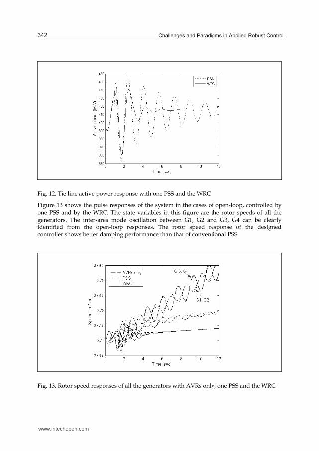
Fig. 12. Tie line active power response with one PSS and the WRC
Figure 13 shows the pulse responses of the system in the cases of open-loop, controlled by one PSS and by the WRC. The state variables in this figure are the rotor speeds of all the generators. The inter-area mode oscillation between G1, G2 and G3, G4 can be clearly identified from the open-loop responses. The rotor speed response of the designed controller shows better damping performance than that of conventional PSS.
Fig. 13. Rotor speed responses of all the generators with AVRs only, one PSS and the WRC
www.intechopen.com
Wide-Area Robust H2/H∞ Control with Pole Placement for Damping Inter-Area Oscillation of Power System
343
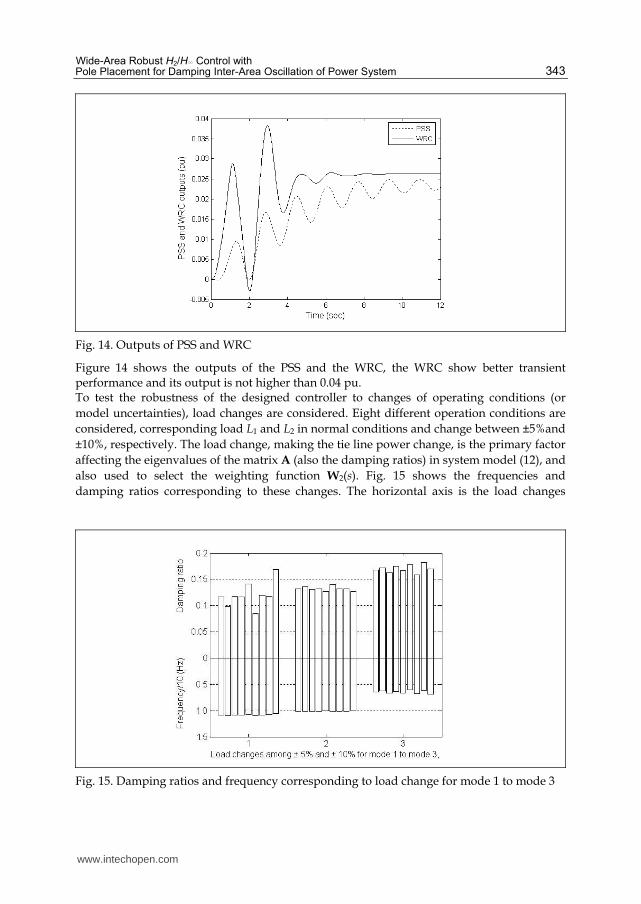
Fig. 14. Outputs of PSS and WRC
Figure 14 shows the outputs of the PSS and the WRC, the WRC show better transient performance and its output is not higher than 0.04 pu. To test the robustness of the designed controller to changes of operating conditions (or
model uncertainties), load changes are considered. Eight different operation conditions are
considered, corresponding load L1 and L2 in normal conditions and change between ±5%and
±10%, respectively. The load change, making the tie line power change, is the primary factor
affecting the eigenvalues of the matrix A (also the damping ratios) in system model (12), and
also used to select the weighting function W2(s). Fig. 15 shows the frequencies and
damping ratios corresponding to these changes. The horizontal axis is the load changes
Fig. 15. Damping ratios and frequency corresponding to load change for mode 1 to mode 3
www.intechopen.com

Challenges and Paradigms in Applied Robust Control
344
(including the nominal operating condition) for mode 1 to mode 3. The upper vertical axis is the damping ratios corresponding to each load change, the lower vertical axis is the frequencies corresponding to each damping ratio. For inter-area mode, mode 3, the damping ratios are higher than 0.15 in all these load levels. The damping rations of the whole system is higher than 0.08 in all cases. The controlled system has proper damping performance and keeps robustness against the variations of system loads.
6. Conclusion
This chapter applies robust control theory to power system, to design wide-area robust
damping controller to cope with inter-area oscillation. Both local signal and suitable chosen
PMU-provided remote signal are utilized to construct the feedback loop. A conception
named participation vector is used for facilitating the positioning of controller, and the
residue is utilized to select suitable remote signal. The controller is designed based on mixed
H2/H∞ output-feedback control with pole placement, and the controller parameters are
obtained through solving a family of linear matrix inequalities. The designed controller is
applied on a 4-generator power system model. The computer simulations are performed for
pulse disturbance as well as system operating changes. The designed controller shows better
damping than conventional PSS and keeps robustness with load variations.
7. Appendix: Benchmark system model parameters
Synchronous machine data (pu)
Xd=1.8, Xd'=0.3, Xd″=0.25, Xq=1.7, Xq'=0.55, Xq″=0.25, Xl=0.2, Ra=0.0025, Td0'=8, Td0″=0.03,
Tq0'=0.4, Tq0″=0.05, H1=6.5, H2=6.175.
Transmission system data in per unit
r=0.0001, xL=0.001, bC=0.0018, xT=0.15.
Excitation system data (pu)
KA=200, TR=0.01, EFMAX=12.3, EFMIN =0.
Generation (power flow results calculated by Matlab-Simulink) (MW, MVar)
G1: P=700, Q=146.5; G2: P=678.9, Q=137.3;
G3: P=719, Q=138.1; G4: P=700, Q=109.1.
Load model (MW, MVar)
L1: PL= 967, QL=100, QC=187;
L2: PL= 967, QL=100, QC=187.
Shunt capacitor: (MVar)
C1: QC=100; C2: QC=250.
8. Acknowledgment
The authors thank Prof. Guangxiong Wang and Prof. Huijun Gao, Harbin Institute of
Technology, for their kindly discussions on robust control theory.
www.intechopen.com

Wide-Area Robust H2/H∞ Control with Pole Placement for Damping Inter-Area Oscillation of Power System
345
9. References
Klein, M.; Rogers, G. J. & Kundur, P. (1991). A Fundamental Study of Inter-Area Oscillations in Power Systems. IEEE Trans. Power Syst., Vol. 6, No. 3, pp. 914-921, ISSN: 0885-8950
Kundur, P. (1994). Power System Stability and Control. McGraw-Hill Professional, ISBN 007035958X, New York, USA
Rogers, M. G. (2000). Power System Oscillations. Springer, ISBN 978-0-7923-7712-2, Boston, USA
Zhou, X. X.; Yi, J.; Song, R. H.; Yang, X. Y.; Lia, Y. & Tang, H. Y. (2010) et al, An Overview of Power Transmission Systems in China, Energy, Vol. 35, Issue 11, pp. 4302-4312, ISSN: 1540-7977
Larsen, E. V. & Swann, D. A. (1981). Applying Power System Stabilizers, Part I-III. IEEE Trans. Power Apparat. Syst., Vol. PAS-100, Issue.6, ( February 1981), pp. 3017 - 3024, ISSN: 0018-9510
Farsangi, M. M.; Song, Y. H. & Tan, M.(2003). Multi-Objective Design of Damping Controllers of Facts Devices via Mixed H2/H∞ With Regional Pole Placement.
Electrical Power and Energy Systems, Vol. 25, pp. 339-346, ISSN: 0142-0615 Pal, B. C.; Coonick, A. H. & Cory, B. J. (2001). Linear Matrix Inequality Versus Root-Locus
Approach for Damping Inter-Area Oscillations in Power Systems, Electrical Power and Energy Systems, Vol. 23, No. 6, pp. 481-489, ISSN: 0142-0615
Chaudhuri, B.; Pal, B. C.; Zolotas, A. C.; Jaimoukha, I. M. & Green, T. C. (2003). Mixed-Sensitivity Approach to H∞ Control of Power System Oscillations Employing
Multiple Facts Devices, IEEE Trans. Power Syst., Vol. 18, No. 3, pp. 1149-1156, ISSN: 0885-8950
Chaudhuri, B. & Pal, B. C. (2004). Robust Damping of Multiple Swing Modes Employing Global Stabilizing Signals With a TCSC, IEEE Trans. Power Syst., Vol. 19, No. 1, pp. 499-506, ISSN: 0885-8950
Snyder, A. F.; Hadjsaid, N.; Georges, D.; Mili, L.; Phadke, A. G.; Faucon, O. & Vitet, S. (1998). Inter-Area Oscillation Damping With Power System Stabilizers and Synchronized Phasor Measurements, Proceedings of International Conference on Power System Technology, pp.790-794, ISBN: 0-7803-4754-4, Beijing , China, August 1998.
Kamwa, I.; Grondin, R.; & Hebert, Y. (2001). Wide-Area Measurement Based Stabilizing Control of Large Power Systems -A Decentralized/Hierarchical Approach, IEEE
Trans. Power Syst., Vol. 16, pp. 136-153, ISSN: 0885-8950 Phadke, A. G. (1993). Synchronized Phasor Measurement in Power Systems, IEEE Computer
Applications in Power, Vol. 6, No. 2, pp. 10-15, ISSN: 0895-0156 Doyle, J. C.; Glover, K.; Khargonekar, P. P. & Francis B. A. (1989). State-space solutions to
standard H2 and H∞ control problems, IEEE Trans. Automat. Contr., Vol. 34, No. 8, pp. 831–847, ISSN: 0018-9286
Zhou, K.; Doyle, J. C. (1998). Essentials of Robust Control. Prentice Hall, ISBN 0-13-525833-2, New Jersey, USA
Chilali, M.; Gahinet, P. (1996). H∞ Design With Pole Placement Constraints: An LMI Approach, IEEE Trans. Automat. Contr., Vol. 41, No. 3, pp. 358-367, ISSN: 0018-9286
Boyd, S.; Ghaoui, L. El; Feron, E. & Balakrishnan, V. (1994). Linear Matrix Inequalities in System and Control Theory, Volume 15 of Studies in Applied Mathematics. SIAM, ISBN 0-89871-334-X, Philadelphia, PA, June 1994.
www.intechopen.com

Challenges and Paradigms in Applied Robust Control
346
Scherer C. W. & Weiland S (2005). Lecture notes DISC course on linear matrix inequalities in control-2004/2005. Delft University of Technology, Netherlands. Compilation: pp. 70-71. [Online]. Available: http://www.cs.ele.tue.nl/sweiland/lmi.html
Scherer, C. W.; Gahinet, P.; Chilail, M. (1997). Multiobjective Output- Feedback Control via LMI Optimization, IEEE Trans. Automat. Contr., Vol. 42, No. 7, pp. 896-911, ISSN: 0018-9286
Nesterov, Y. & Nemirovski, A. (1994). Interior Point Polynomial Algorithms in Convex Programming. SIAM publications, ISBN: 0898715156, Philadelphia, USA
Gahinet, P.; Nemirovskii, A.; Laub, A. J. & Chilali, M. (1995). LMI Control Toolbox. The MathWorks Inc, 1995.
www.intechopen.com

Challenges and Paradigms in Applied Robust ControlEdited by Prof. Andrzej Bartoszewicz
ISBN 978-953-307-338-5Hard cover, 460 pagesPublisher InTechPublished online 16, November, 2011Published in print edition November, 2011
InTech EuropeUniversity Campus STeP Ri Slavka Krautzeka 83/A 51000 Rijeka, Croatia Phone: +385 (51) 770 447 Fax: +385 (51) 686 166www.intechopen.com
InTech ChinaUnit 405, Office Block, Hotel Equatorial Shanghai No.65, Yan An Road (West), Shanghai, 200040, China
Phone: +86-21-62489820 Fax: +86-21-62489821
The main objective of this book is to present important challenges and paradigms in the field of applied robustcontrol design and implementation. Book contains a broad range of well worked out, recent application studieswhich include but are not limited to H-infinity, sliding mode, robust PID and fault tolerant based controlsystems. The contributions enrich the current state of the art, and encourage new applications of robustcontrol techniques in various engineering and non-engineering systems.
How to referenceIn order to correctly reference this scholarly work, feel free to copy and paste the following:
Chen He and Bai Hong (2011). Wide-Area Robust H2/H∞ Control with Pole Placement for Damping Inter-AreaOscillation of Power System, Challenges and Paradigms in Applied Robust Control, Prof. Andrzej Bartoszewicz(Ed.), ISBN: 978-953-307-338-5, InTech, Available from: http://www.intechopen.com/books/challenges-and-paradigms-in-applied-robust-control/wide-area-robust-h2-h-control-with-pole-placement-for-damping-inter-area-oscillation-of-power-system