why grounding?
TRANSCRIPT

Introduction
WHY GROUNDING?
By grounding or earthing we mean making a connection to the general mass of earth. Practically every point of the supply network, from the generators to the apparatus on the consumers’ earth electrodes will be found. Some standards discriminate between grounding and earthling, it define erthing as connecting to earth, but grounding is defined as common reference to the network. In this book grounding and earthing will be used as the same meaning. The purposes of grounding are:
1. Increases the reliability of the supply service2. It helps to provide stability of voltage conditions, preventing excessive
voltage sparks during disturbances3. It provides protection against lightning4. It creates path for the protection of electrical networks against earth
faults5. It ensures safety for human and animal’s bodies by discharging the
electrical energy to the earth6. To provide means to carry electric currents into the earth under normal
and fault conditions without exceeding any operating and equipment limits or adversely affecting continuity of service.
7. To assure that a person in the vicinity of grounded facilities is not exposing to the danger of critical electric shock.
GROUNDING OR EARTHING PRINCIPLES DEFINITIONS
Grounding or Earthing
It is defined as a connection to general mass of earth by means of an earth electrode. An object is earthed when it is electrically connected to an earth
viii
Introduction
electrode by a conductor. Practically the earthing or grounding can be classified to neutral or power grounding in which the neutral point is connected to the earth and safety grounding in which the metallic cover or sheath of the equipment is connected to the earth.
Solidly Grounding
When the object is electrically connected to an earth electrode without a fuse, switch circuit breaker, resistance or impedance in the earth connection, the object grounding is define as solid grounding.
Earth Electrode
It is defined as a metal plate, rod, grid or other conductors buried in or driven into the ground and used for grounding metal work of electrical network.
Grounding Lead
The final conductor by which the connection to the earth electrode is made
Live Object
An object is said to be live when:
1. A difference of potential exists between it and earth2. It is connected to common return, or neutral of a supply system in which
such common return or neutral is not solidly earthed.
Earth Leakage Switch
It is an automatic device used to disconnect faulty appliances and is operated by a small leakage current flowing as result of the connection of the metal work to an earth electrode through the operating coil of the switch.
Core Balance Relay
An automatic device to disconnect faulty appliances as result of the out of balance currents of the supply circuit to the leakage of part of the current to earth through an earth electrode connected to the frame.
ix

Introduction
Grounding Resistance
The ohmic resistance between an earth electrode system and general mass of earth is defined as grounding resistance. In the case of consumer grounding, the resistance is the sum of the resistance of the consumer earth continuity conductor and grounding rod, and the resistance of the earth electrode to the general mass of earth. Measurements show that 90% of the total resistance around an earth rod is within a radius of three meters.
Earth Resistivity
It could be in ohms per cubic centimeter of a sample of earth, or in ohm. Meter
Ground Potential Rise (GPR)
It is the maximum electrical potential that a substation grounding grid may attain relative to a distant grounding point assumed to be at the potential of remote earth. This voltage, (GPR), equals the maximum grid current times the grid resistance as reported by the IEEE 80 standard (2000).
Mesh Voltage
It is the maximum touch voltage within a mesh of a ground grid as explained by the IEEE 80 standard (2000)
Step Voltage
It is defined as the difference in surface potential experienced by a person bridging a distance of 1 m with the feet without contacting any other grounded object.
The IEEE 80 standard (2000) uses the maximum mesh voltage as the touch voltage, and this usually exists at the corner mesh. UK practice (2011) defines the touch voltage differently. In practice, the voltage at the surface of the ground is a maximum adjacent to a corner of a grid. UK practice is to define touch voltage as the sum of the step voltage plus the voltage difference between the ground surface adjacent to a corner and the grid beneath. Although the mesh voltage is used as the defining touch voltage in American practice, the maximum permitted touch voltage used is less than that used in British
x
Introduction
Standards. In practice, compliance with American usage thus also ensures the arrangement will comply with UK requirements.
Touch Voltage
It is defined as the potential difference between the ground potential rise (GPR) and the surface potential at the point where a person is standing while at the same time having a hand in contact with a grounded structure. This is reported by the IEEE 80 standard (2000)
Transferred Voltage
It is considered as a special case of the touch and step voltages where the voltage is transferred into or out of the substation from or to a remote point external to the substation site
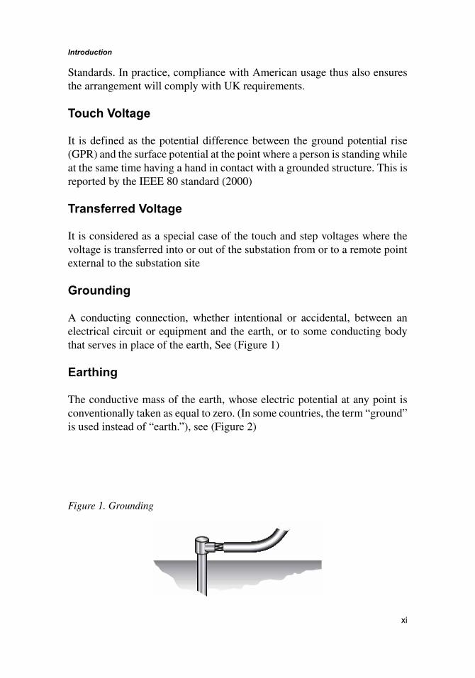
Grounding
A conducting connection, whether intentional or accidental, between an electrical circuit or equipment and the earth, or to some conducting body that serves in place of the earth, See (Figure 1)
Earthing
The conductive mass of the earth, whose electric potential at any point is conventionally taken as equal to zero. (In some countries, the term “ground” is used instead of “earth.”), see (Figure 2)
Figure 1. Grounding
xi

Introduction
Grounding Grid
A system of horizontal ground electrodes that consists of a number of interconnected, bare conductors buried in the earth, providing a common ground for electrical devices or metallic structures, usually in one specific location.
Grounding Mat
A solid metallic plate or a system of closely spaced bare conductors that are connected to and often placed in shallow depths above a ground grid or elsewhere at the earth surface, in order to obtain an extra protective measure minimizing the danger of the exposure to high step or touch voltages in a critical operating area or places that are frequently used by people. Grounded metal gratings placed on or above the soil surface or wire mesh placed directly under the crushed rock, are common forms of a ground mat.
Bonding
It is defined as the permanent joining of metallic parts to form an electrically conductive path that will ensure electrical continuity and the capacity to conduct safely any current likely to be imposed. See (Figure 3)
Figure 2. Earthing
Figure 3. Bonding
xii
Introduction
Ungrounded System
A power system not having any intentional connection to ground is referred to as an ungrounded system. However, because of the capacitive coupling between the phase conductors and ground, an ungrounded system is in reality grounded through the distributed capacitance of the system conductors to ground. A line to ground fault on an ungrounded system cause a very small ground fault current to flow through the capacitance of cables, transformers, and other electrical equipment on the system. Thus, ungrounded systems are designed to operate such that phase over current devices do not trip for the first phase to ground fault. If a second ground fault occurs on another phase, the result is a line to line fault with high fault current. The relatively high current of the L-L fault should trip phase over current devices, as it would with the high resistance grounded system.
OBJECTIVES OF SAFE GROUNDING DESIGN
The good grounding design of the electrical networks must achieve two main goals:
1. To provide means to carry electric currents into the earth under normal and fault conditions without exceeding any operating and equipment limits or adversely affecting continuity of service.
2. To assure that a person in the vicinity of grounded facilities is not exposed to the danger of critical electric shock.
A good grounding system should satisfy the following criteria:
• To provide a low impedance return path for surge current which is necessary for the timely operation of the over current/voltage protection system.
• To reduce the risks of breakdown hazard to electrical systems or electronic equipment.
• To reduce electric shock hazard to personnel.• To minimize the cost of the grounding system.
For the electrical/electronic systems connected to the grounding structure, the voltage/ (voltage difference) due to the surge current should not be larger
xiii
Introduction
than the breakdown value of the system. It is well known that different systems have different breakdown voltages. In order to meet the above said criteria, there are several basic rules that should be followed:
1. The size of the grounding system should be large enough to reduce the maximum potential rise when the surge current enters it.
2. The spacing between the grounding wires should be so arranged that the touch and step voltages will be smaller than the safe value for the personnel.
3. The downward conductor should be connected to the grounding system at such points in order to reduce the ground potential rise, for example, at the mid-point of the grounding system.
4. For different soil structures, the grounding system should be laid in such a way that it can take advantage of the low resistivity part of the soil to reduce the ground potential rise as much as possible.
5. The effective length/area should be considered when one tries to minimize the cost.
6. Consequently, a good grounding system can dissipate the fault/lightning current into the soil as fast as possible, thereby, reduce the potential rise and potential difference within the different parts of the system and finally, there will be minimum damage to inter connected electronic devices and injury to the personnel working on site.
ADVANTAGES OF GROUNDING
The following are the grounded network merits:
1. The star point is always at earth potential to that when an earth fault occurs on one line. The potential difference between the healthy line and earth cannot exceed the phase voltage.
2. The maintenance and operation expenses are less.3. Simple protection system based on the direction of the earth leakage
current.4. The system provides greater safety to person and equipment.5. An arc in ground fault cannot occur.6. The system provides a reliable service.
xiv

Introduction
DESIGN CONSIDERATION OF GROUNDING SYSTEM
Some parameters have to be considered in designing the grounding system of electrical networks and apparatus. These parameters include:
1. Purpose of facility2. Design life of facility3. Soil resistivity at three different depths4. Corrosive nature of soil5. Shape and available area of facility site6. Existing structures and their grounding systems7. Seasonal variations in moisture and temperature for facility site8. Public access and personnel use9. Adjacent facilities and electrical systems10. Future uses, additions, equipment for facility
For proper operation of over current devices, it is important to have a low DC ohmic resistance to remote earth. In many instances, this is best achieved by installing a deep ground electrode on site. It should be driven deep enough to reach the permanent water table. For dissipation of direct or indirect lightning currents, it is better to have many horizontal ground conductors in the soil, preferably in a radial array. This provides a low impedance path of dissipation to the high frequency component of the lightning energy. For safety of personnel, particularly where people congregate or where equipment operators will be located, it is important to have a grid system or other equipotential plane to reduce “step potential” and have equipment and metal structures bonded to the ground system to reduce “touch potential”.
A proper facility grounding system incorporates these necessities in the most cost-effective manner that will last for the design life of the facility.
GROUNDING RESISTANCE VALUES
There is a good deal of confusion as to what constitutes a good ground and what the ground resistance value needs to be. Ideally a ground should be of zero ohms resistance. The NEC has stated that “A single electrode consisting of a rod, pipe, or plate which does not have a resistance to ground of 25 ohms or less shall be augmented by one additional electrode.” Once you have added the supplemental ground you have met the requirement for the NEC.
xv
Introduction
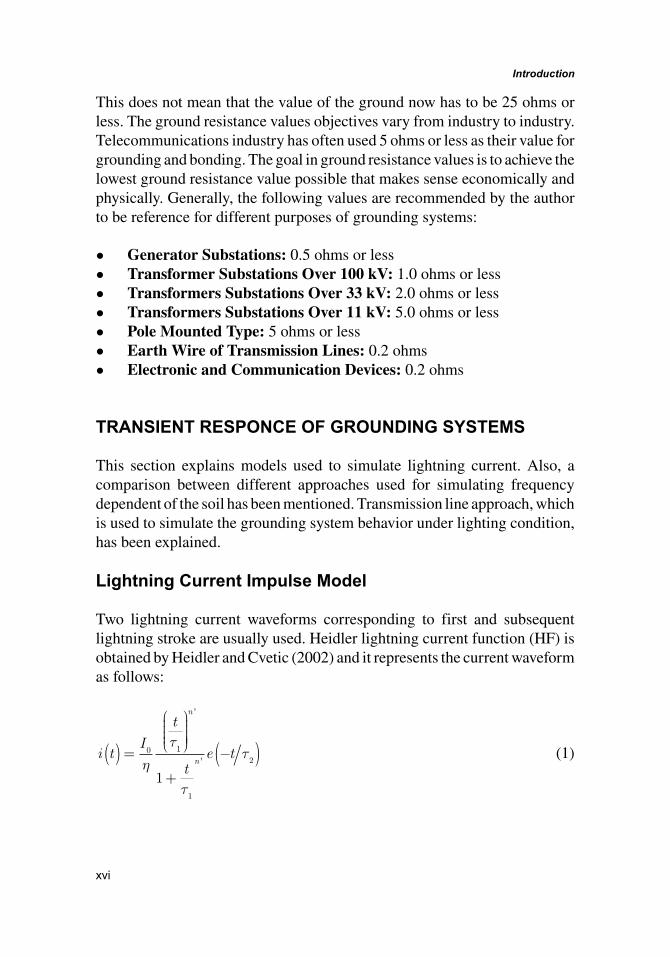
This does not mean that the value of the ground now has to be 25 ohms or less. The ground resistance values objectives vary from industry to industry. Telecommunications industry has often used 5 ohms or less as their value for grounding and bonding. The goal in ground resistance values is to achieve the lowest ground resistance value possible that makes sense economically and physically. Generally, the following values are recommended by the author to be reference for different purposes of grounding systems:
• Generator Substations: 0.5 ohms or less• Transformer Substations Over 100 kV: 1.0 ohms or less• Transformers Substations Over 33 kV: 2.0 ohms or less• Transformers Substations Over 11 kV: 5.0 ohms or less• Pole Mounted Type: 5 ohms or less• Earth Wire of Transmission Lines: 0.2 ohms• Electronic and Communication Devices: 0.2 ohms
TRANSIENT RESPONCE OF GROUNDING SYSTEMS
This section explains models used to simulate lightning current. Also, a comparison between different approaches used for simulating frequency dependent of the soil has been mentioned. Transmission line approach, which is used to simulate the grounding system behavior under lighting condition, has been explained.
Lightning Current Impulse Model
Two lightning current waveforms corresponding to first and subsequent lightning stroke are usually used. Heidler lightning current function (HF) is obtained by Heidler and Cvetic (2002) and it represents the current waveform as follows:
i tI
t
te t
n
n( ) =
+
−( )0 1
1
2
1η
τ
τ
τ
'
' (1)
xvi

Introduction
ηττ
ττ
=−
′′
en
n1
2
2
1
1
(2)
where
I0 = the amplitude of the current pulse.τ
1 = the front time constant.τ
2 = the decay time constant.′n = exponent having values between 2 to 10.η = the amplitude correction factor.
The first stroke waveform is reproduced by one and the subsequent stroke is reproduced by the sum of two Heidler’s functions with the parameters given
Table 1. Parameters for the return stroke currents
ParametersI0 τ1 τ2 ′n I0 τ1 τ2 ′n
First stroke 28 1.8 95 2 -- -- -- --
Subsequent stroke 10.7 0.25 2.5 2 6.5 2 230 2
Figure 4. Typical waveforms of lightning first and subsequent return strokeAdapted by Heidler and Cvetic (2002).
xvii

Introduction
in Table 1. (Figure 4) shows lightning current wave of first and subsequent return stroke according to equations 1 and 2.
Modeling of Grounding System Under Lightning
There are several numerical methods used to study the performance of grounding systems under lightning current stroke such as:
1. Circuit approach as reported by Leonid Grcev (2009)2. Transmission line approach as discussed by L. Grcev and S. Grceva,
(2009).3. Electromagnetic field approach as reported by L.Grcev and F. Dawalibi,
(1990).4. Hybrid approach as reported by P. Yuttagowith, A. ametani, N. Nagaoka,
and Y. Baba, (2011).
Transmission line method is usually used by the authors to simulate the grounding grids as transmission line. In this method, any transmission line is divided into N segment each segment consists of R C
g g, , and L
g. The
formula of R Cg g, , and L
g are as follows:
Resistance for vertical electrode is
Rlag
= −
ρπ2
41ln (3)
And the resistance for the horizontal electrode is
Rl
adg= −
ρπln
2
21 (4)
The grounding capacitance is
CRg
=ρε (5)
The inductance of electrode is
xviii

Introduction
Llag
= −
� ln
µπ2
21 (6)
where μ is permeability of soil (H/m)After calculating the parameter of the transmission line, the transient
behavior of grounding systems can be simulated by ATP-EMTP, ATP rule book, Can/Am EMTP User Group, (1995). In ATP-EMTP, each electrically small segment of the transmission line is represented by lumped resistance, inductance, and capacitance. The number of the segments required for an accurate simulation is dependent on the highest frequency of the injected impulse, the higher the frequency, the larger the number of sections is required. Another solution to simulate transient behavior of grounding systems is simple analytical equation. These simplified equations are used to calculate the harmonic impedance, transient voltage, impulse impedance, impulse coefficient, effective length and decrement factor.
1. Harmonic Impedance: One of the most important properties in the high-frequency analysis of grounding system is harmonic impedance to ground Z jw( ) . It can be computed as the input impedance of an open transmission line in frequency domain as reported by Leonid Grcev (2000) and (2007). This is discussed also by Grcev, Markovski, Arnautovski-Toseva et al. (2012).
Z jw Z lo( ) = ( )coth γ (7)
Zj L
Rj C
g
gg
0
1=
+
ω
ω
(8)
γ ω ω= +
j LR
j Cg
gg
1 � (9)
xix
Introduction
From above equations, it is noticed that the harmonic impedance depends on only geometry, electromagnetic properties of the ground system and electric soil parameter.
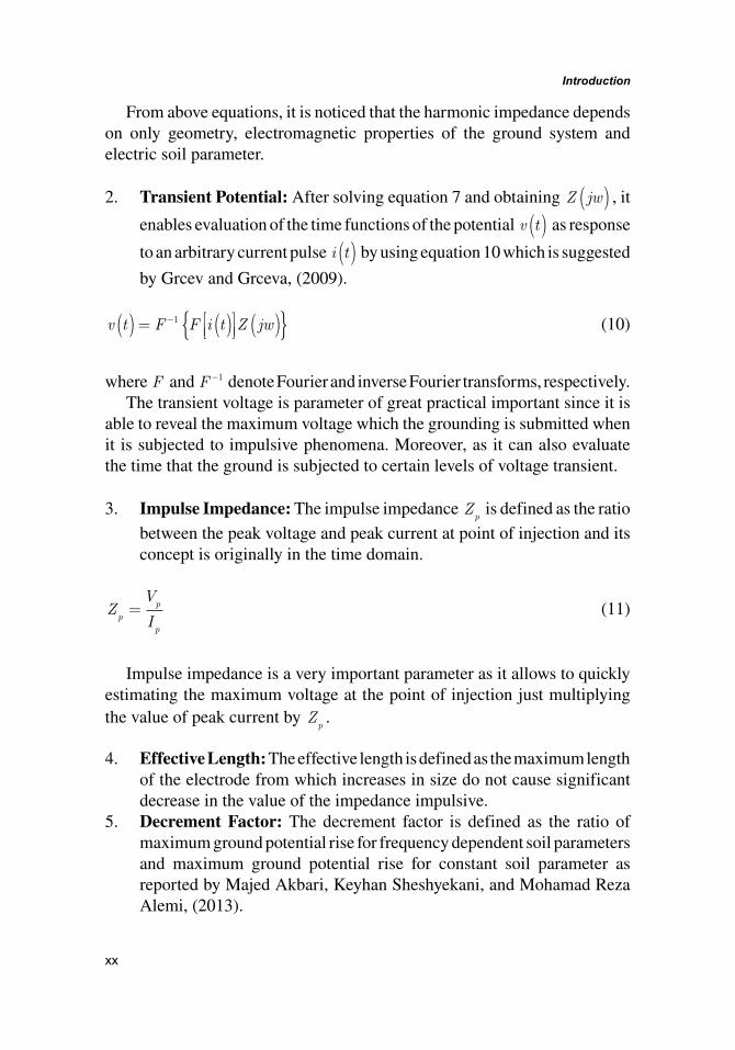
2. Transient Potential: After solving equation 7 and obtaining Z jw( ) , it enables evaluation of the time functions of the potential v t( ) as response to an arbitrary current pulse i t( ) by using equation 10 which is suggested by Grcev and Grceva, (2009).
v t F F i t Z jw( ) = ( ) ( ){ }−1 (10)
where F and F−1 denote Fourier and inverse Fourier transforms, respectively.The transient voltage is parameter of great practical important since it is
able to reveal the maximum voltage which the grounding is submitted when it is subjected to impulsive phenomena. Moreover, as it can also evaluate the time that the ground is subjected to certain levels of voltage transient.
3. Impulse Impedance: The impulse impedance Zp is defined as the ratio
between the peak voltage and peak current at point of injection and its concept is originally in the time domain.
ZV
Ipp
p
= (11)
Impulse impedance is a very important parameter as it allows to quickly estimating the maximum voltage at the point of injection just multiplying the value of peak current by Z
p.
4. Effective Length: The effective length is defined as the maximum length of the electrode from which increases in size do not cause significant decrease in the value of the impedance impulsive.
5. Decrement Factor: The decrement factor is defined as the ratio of maximum ground potential rise for frequency dependent soil parameters and maximum ground potential rise for constant soil parameter as reported by Majed Akbari, Keyhan Sheshyekani, and Mohamad Reza Alemi, (2013).
xx
Introduction
DFGPRforfrequencydependentsoilparameter
GPRforc=
{ }�max� �
max oons tsoilparametertan ��
{ } (12)
Frequency Dependent Soil Models
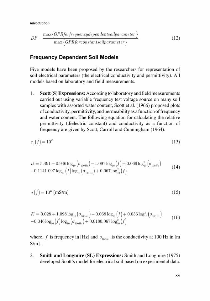
Five models have been proposed by the researchers for representation of soil electrical parameters (the electrical conductivity and permittivity). All models based on laboratory and field measurements.
1. Scott (S) Expressions: According to laboratory and field measurements carried out using variable frequency test voltage source on many soil samples with assorted water content, Scott et al. (1966) proposed plots of conductivity, permittivity, and permeability as a function of frequency and water content. The following equation for calculating the relative permittivity (dielectric constant) and conductivity as a function of frequency are given by Scott, Carroll and Cunningham (1964).
εr
Df( ) = 10 (13)
D fHz Hz
= + ( )− ( )+5 491 0 946 1 097 0 06910 100 10 10
2100
. . log . log . logσ σ(( )− ( ) ( )+ ( )0 1141 097 0 067
10 10 100 102. . log log . logf f
Hzσ
(14)
σ f( ) = 10K [mS/m] (15)
K fHz Hz
= + ( )− ( )+0 028 1 098 0 068 0 03610 100 10 10
2100
. . log . log . logσ σ(( )− ( ) ( )+ ( )0 046 0 0180 067
10 10 100 102. log log . . logf f
Hzσ
(16)
where, f is frequency in [Hz] and σ100Hz
is the conductivity at 100 Hz in [m S/m].
2. Smith and Longmire (SL) Expressions: Smith and Longmire (1975) developed Scott’s model for electrical soil based on experimental data.
xxi
Introduction
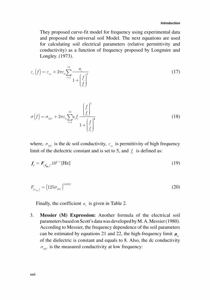
They proposed curve-fit model for frequency using experimental data and proposed the universal soil Model. The next equations are used for calculating soil electrical parameters (relative permittivity and conductivity) as a function of frequency proposed by Longmire and Longley. (1973).
ε ε πεr
i
i
i
fa
ff
( ) = +
+
∞=∑2
1
01
13
2 (17)
σ σ πεf a f
ff
ff
DCi
i ii
i
( ) = +
+
=∑2
1
01
13
2
22 (18)
where, σDC
is the dc soil conductivity, ε∞ is permittivity of high frequency limit of the dielectric constant and is set to 5, and f
i is defined as:
f Fi Ãi
DC= ( )
−.10 1 [Hz] (19)
FDC
DCσσ( ) = ( )125
0 8312. (20)
Finally, the coefficient ai is given in Table 2.
3. Messier (M) Expression: Another formula of the electrical soil parameters based on Scott’s data was developed by M. A. Messier (1980). According to Messier, the frequency dependence of the soil parameters can be estimated by equations 21 and 22, the high-frequency limit µ∞ of the dielectric is constant and equals to 8. Also, the dc conductivity σDC
is the measured conductivity at low frequency:
xxii

Introduction
εεε
σπ εrDCff
( ) = +
∞
∞0
1 (21)
σ σπ εσ
ff
DCDC
( ) = +
∞1
4 [S/m] (22)
4. Visacor and Portola (VP) Expressions: Based on the Laboratory measurements of many soil samples in the frequency range 40 Hz to 2 MHz Visacor and Portela (2007) developed empirical equations for soil permittivity and conductivity as function of frequency as follows
εσr
Hz
f f( ) = ×
⋅−
−2 34 1016
100
0 535
0 597.
.
. (23)
Table 2. Coefficients ai for universal soil
i ai
1 3.4 × 10⁶
2 2.74 × 10⁵
3 2.58 × 10⁴
4 3.38 × 10³
5 5.26 × 10²
6 1.33 × 10²
7 2.72 × 101
8 1.25 × 101
9 4.8 × 100
10 2.17 × 100
11 9.78 × 10⁻¹
12 3.92 × 10⁻¹
13 1.73 × 10⁻¹
Reported by Cavka, Mora and Rachidi (2014).
xxiii
Introduction
σ σff
Hz( ) =
100
0 072
100
.
(24)
5. Visacor and Alipio (VA) Expression: A new expression based on experimental data to determine the frequency variation of soil resistivity and permittivity is suggested by Visacor and Alipio (2012). The following equations are formed by the authors based on measurements in field condition:
εrf f f( ) = × +−7 6 10 1 33 0 4. .. (26)
σ σσ
fHz
Hz
( ) = × + ×
−100
6
100
0 73
1 1 2 101
.
.
ff −( )
1000 63.
(27)
The frequency range suggested by above models is 10 KHz to 4 MHz for relative permittivity, while it is 100 KHz to 4MHz for conductivity.
REFERENCES
Akbari, M., Sheshyekani, K., & Alemi, M. R. (2013). The effect of frequency dependence of soil electrical parameters on the lightning performance of grounding systems. IEEE Trans. Electromagnetic Compatibility, 55(4), 739–746.
Damir, C., Nicolas, M., & Farhad, R. (2014). A Comparison of Frequency-Dependent Soil Models: Application to the Analysis of Grounding Systems. IEEE Transactions on Electromagnetic Compatibility, 56(1), 177–187. doi:10.1109/TEMC.2013.2271913
Grcev, L. (2007). Impulse efficiency of grounding electrode arrangements. In Proceedings of the 18th International Conference Zurich symposium on EMC, Munich /Germany (pp. 325-328).
Grcev, L., & Grceva, S. (2009). On high-frequency circuit of horizontal grounding electrodes. IEEE Transactions on Electromagnetic Compatibility, 51(3), 873–875. doi:10.1109/TEMC.2009.2023330
xxiv
Introduction
Grcev, L., Markovski, B., Arnautovski-Toseva, V., & Drissi, K. E. K. (2012). Transient analysis of grounding systems without computer. In Proceedings of the International Conference on Lightning Protection, Vienna, Austria.
Heidler, F., & Cvetic, J. (2002). A Class of analytical functions to study the lightning effects associated with the current front. Electrical Energy Systems, 12(2), 141–150.
IEEE. (2000). Std. 80. IEEE Guide for Safety in AC Substation Grounding.
IEEE. (2011). Code of Practice for Protective Earthing of Electrical Installations, BS7430 IEEE 80, 2000 BS7430.
Leonid, G. (2000). High-frequency performance of ground rods in highly resistive soil. In Proceedings of the International Conference on grounding and earthing, Belo Horizonte, Brazil (pp. 85-89).
Longmire, C. L., & Longley, H. J. (1973). Time domain treatment of media with frequency parameters (Theoretical Notes 113). Defense Nuclear Agency, Santa Barbara, CA. Retrieved from https://www.ece.unm.edu/summa/notes/Theoretical.html
Messier, M. A. (1980). The propagation of an electromagnetic impulse through soil: Influence of frequency dependent parameters (Tech. Rep. MRC-N-415). Mission Res. Corp., Santa Barbara, CA.
Scott, J. H. (1966). Electrical and magnetic properties of rock and soil (Theoretical Note 18). U.S. Geological Survey. Retrieved from https://www.ece.unm.edu/summa/notes/Theoretical.html
Scott, J. H., Carroll, R. D., & Cunningham, D. R. (1964). Dielectric Constant and Electrical Conductivity of Moist Rock from Laboratory Measurements, Sensor and Simulation Note 116. NM: Kirtland AFB.
Smith, K.S., & Longmire, C.L. (1975). A universal impedance for soils (Topical Report for Period Jul). Defense Nuclear Agency, Alexandria, VA, USA.
Visacor, S. (2007). A Comprehensive Approach to the Grounding Response to Lightning Currents. IEEE Transactions on Power Delivery, 22(1), 381–386. doi:10.1109/TPWRD.2006.876707
xxv

Introduction
Alipio, R., & Visacro, S. (2012). How the frequency dependence of soil parameters affect the lightning response of grounding electrodes. In Proceedings of the International Conference on Lightning Protection, Vienna, Austria.
xxvi