who better than you to talk about it! -...
TRANSCRIPT

Lexic:who better than you to talk about it!
A COMPLETE RANGE FOR ALL APPLICATIONS

In choosing Lexic, I feel we have opted for a universal
solution which answers all the problems we may
encounter on site. This complete range guarantees consistency
and uniformity in our consumer units.
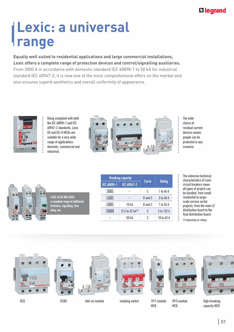
Breaking capacityCurve Rating
IEC 60898-1 IEC 60947-2
3000 - C 1 to 40 A
4500 - B and C 2 to 40 A
6000 10 kA B and C 1 to 63 A
10000 12.5 to 25 kA(1) C 2 to 125 A
- 50 kA C 10 to 63 A
LExIC ALso InCLudEs a complete range of additional functions: signalling, time delay, etc.
Lexic: a universal range
Equally well suited to residential applications and large commercial installations, Lexic offers a complete range of protection devices and control/signalling auxiliaries. From 3000 A in accordance with domestic standard IEC 60898-1 to 50 kA for industrial standard IEC 60947-2, it is now one of the most comprehensive offers on the market and also ensures superb aesthetics and overall uniformity of appearance.
The extensive technical characteristics of Lexic circuit breakers mean all types of project can be handled, from small residential to large-scale service sector projects, from the main LV distribution board to the final distribution board.(1) depending on ratings
Add-on moduleRCBo 1P/1 module MCB
3P/3 module MCB
Isolating switchRCd High breaking capacity MCB
The wide choice of residual current devices means people can be protected in any scenario.
Being compliant with both the IEC 60898-1 and IEC 60947-2 standards, Lexic dx and dx-H MCBs are suitable for a very wide range of applications: domestic, commercial and industrial.
01

02
I know that Legrand attaches particular importance
to the performance of its Lexic circuit breakers.
Individually tested in the factory and conforming to international
standards such as NF, the user can be sure of high-quality
operation. We find it very reassuring!
03
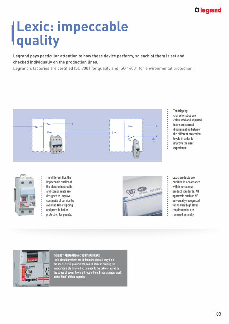
Lexic: impeccable quality
Legrand pays particular attention to how these device perform, so each of them is set and checked individually on the production lines. Legrand's factories are certified ISO 9001 for quality and ISO 14001 for environmental protection.
The tripping characteristics are calculated and adjusted to ensure correct discrimination between the different protection levels in order to improve the user experience.
Lexic products are certified in accordance with international product standards. All approvals such as nF, universally recognised for its very high level requirements, are renewed annually.
The different Hpi, the impeccable quality of the electronic circuits and components are designed to improve continuity of service by avoiding false tripping and provide better protection for people.
THE BEsT-PERFoRMIng CIRCuIT BREAkERsLexic circuit breakers are in limitation class 3: they limit the short-circuit power in the cables and can prolong the installation's life by avoiding damage to the cables caused by the stress of power flowing through them. Products never work at the “limit” of their capacity.

04
I really appreciate the chance to mix and match protection
and control devices on the same row. The Lexic range
offers us real freedom of installation while letting us stick to our
usual wiring practices!
05
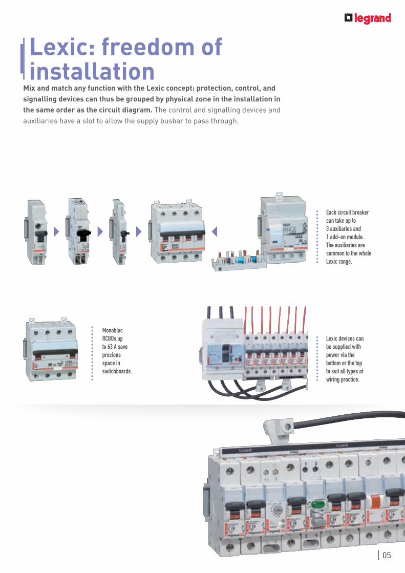
Lexic: freedom of installation
Mix and match any function with the Lexic concept: protection, control, and signalling devices can thus be grouped by physical zone in the installation in the same order as the circuit diagram. The control and signalling devices and auxiliaries have a slot to allow the supply busbar to pass through.
Lexic devices can be supplied with power via the bottom or the top to suit all types of wiring practice.
Monobloc RCBos up to 63 A save precious space in switchboards.
Each circuit breaker can take up to 3 auxiliaries and 1 add-on module. The auxiliaries are common to the whole Lexic range.

The Lexic range is reassuringly well designed. All the
devices have 35 mm² terminals so I can make connections
which are perfectly safe. I have complete peace of mind when wiring
up my switchboards.
06

Lexic: safety and ease of connection
The Lexic range ensures safety of installation and simplifies wiring operations. With wide terminals providing reliable, lasting connections, a wire guide and enhanced cable tensile resistance, Lexic ensures ease of installation and peace of mind.
Prong or fork-type supply busbars eliminate any risk of short-circuits and provide a totally reliable connection via the top or bottom of the device. Easy to use, they can be adapted to suit any type of connection practice.
The Lexic range guarantees IP2x protection. It prevents any risk of contact with live parts, even when the faceplate is open.
Lexic devices have a wire guide flap on their terminals, which avoids connection errors.
ALL LExIC swITCHEs And CIRCuIT BREAkERs HAVE LARgE-CAPACITy 35 MM² TERMInALs FoR EAsE oF ConnECTIon. - The shape of the screws and terminals guarantees excellent
mechanical withstand of the wires and limits the contact impedance, temperature rise and heat loss.
ExCLusIVE To LEgRAnd
07

08
Marking of product characteristics, protected
label holder… really useful features which save me
precious time when undertaking maintenance!

09
Lexic: simplicity and safety of maintenance
The many advantages of the Lexic range can optimise intervention times during maintenance operations without compromising on safety: product marking, circuit identification and coloured handles mean functions can be quickly identified… Genuinely useful features which simplify operation and maintenance.
Circuit diagram
Curve and rated currentBreaking capacity
in accordance with IEC 60898-1Limitation class
Rated voltage
Breaking capacity in accordance with IEC 60947-2
Control handle- grey: isolating switch- black: circuit breaker
double clips on the back of the products can be used to remove individual devices without unscrewing the whole row.
The clear and comprehensive marking on products makes the technical characteristics easier to read and allows the user to intervene quickly without the risk of making a mistake. The state of the contacts can be seen quickly thanks to the colour-coded marking on the handle (red: closed, green: open).
I - on/red o - oFF/green
The label holder on the product front face protects the labels effectively and durably so that the circuits are easily identifiable.
To make it safe to work on the consumer unit and prevent accidental restarts, the handles can be padlocked.

10
CataloguePagesOn the following pages,
you will find all the technical information
and product characteristics for the Lexic offer.
11
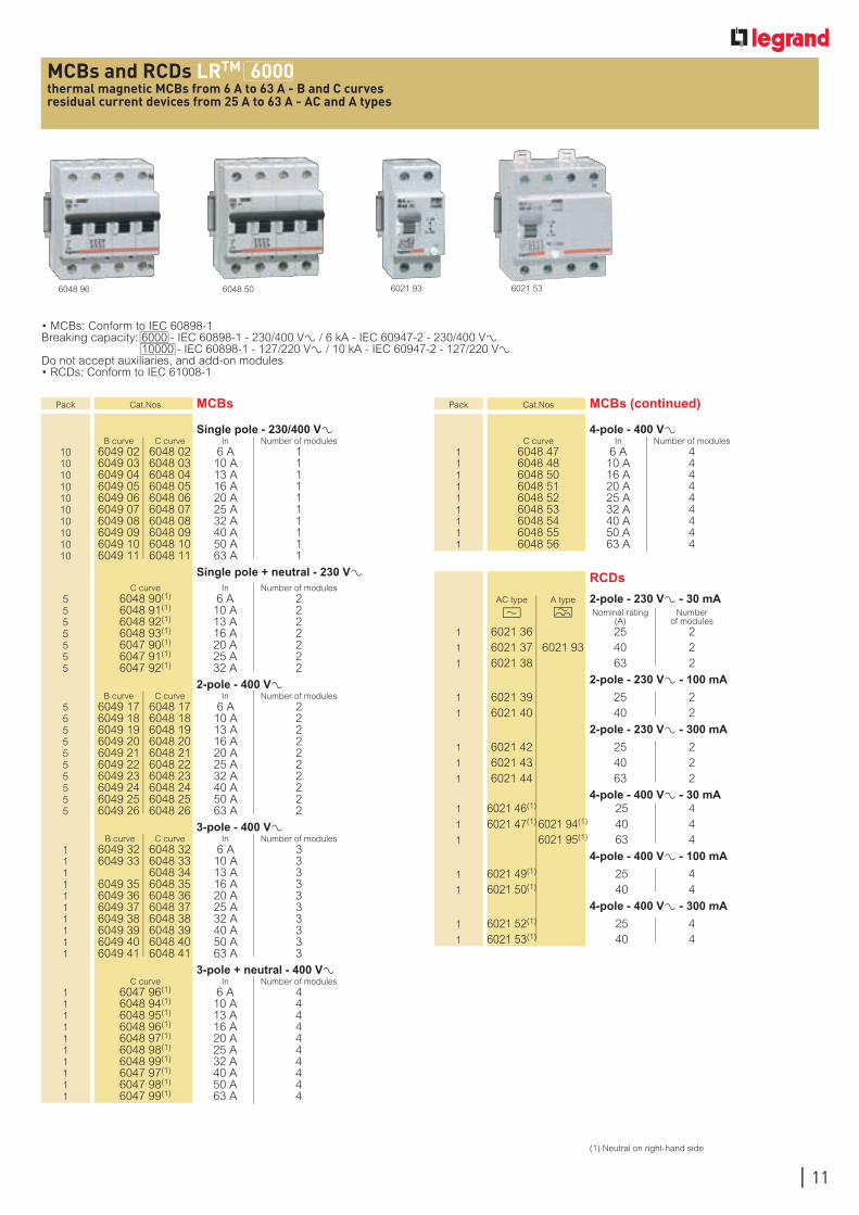
MCBs and RCDs LRTM 6000thermal magnetic MCBs from 6 A to 63 A - B and C curvesresidual current devices from 25 A to 63 A - AC and A types
• MCBs: Conform to IEC 60898-1Breaking capacity: 6000 - IEC 60898-1 - 230/400 V± / 6 kA - IEC 60947-2 - 230/400 V± 10000 - IEC 60898-1 - 127/220 V± / 10 kA - IEC 60947-2 - 127/220 V±Do not accept auxiliaries, and add-on modules• RCDs: Conform to IEC 61008-1
Pack Cat.Nos MCBs
Single pole - 230/400 V± B curve C curve In Number of modules 10 6049 02 6048 02 6 A 1 10 6049 03 6048 03 10 A 1 10 6049 04 6048 04 13 A 1 10 6049 05 6048 05 16 A 1 10 6049 06 6048 06 20 A 1 10 6049 07 6048 07 25 A 1 10 6049 08 6048 08 32 A 1 10 6049 09 6048 09 40 A 1 10 6049 10 6048 10 50 A 1 10 6049 11 6048 11 63 A 1
Single pole + neutral - 230 V± C curve In Number of modules 5 6048 90(1) 6 A 2 5 6048 91(1) 10 A 2 5 6048 92(1) 13 A 2 5 6048 93(1) 16 A 2 5 6047 90(1) 20 A 2 5 6047 91(1) 25 A 2 5 6047 92(1) 32 A 2
2-pole - 400 V± B curve C curve In Number of modules 5 6049 17 6048 17 6 A 2 5 6049 18 6048 18 10 A 2 5 6049 19 6048 19 13 A 2 5 6049 20 6048 20 16 A 2 5 6049 21 6048 21 20 A 2 5 6049 22 6048 22 25 A 2 5 6049 23 6048 23 32 A 2 5 6049 24 6048 24 40 A 2 5 6049 25 6048 25 50 A 2 5 6049 26 6048 26 63 A 2
3-pole - 400 V± B curve C curve In Number of modules 1 6049 32 6048 32 6 A 3 1 6049 33 6048 33 10 A 3 1 6048 34 13 A 3 1 6049 35 6048 35 16 A 3 1 6049 36 6048 36 20 A 3 1 6049 37 6048 37 25 A 3 1 6049 38 6048 38 32 A 3 1 6049 39 6048 39 40 A 3 1 6049 40 6048 40 50 A 3 1 6049 41 6048 41 63 A 3
3-pole + neutral - 400 V± C curve In Number of modules 1 6047 96(1) 6 A 4 1 6048 94(1) 10 A 4 1 6048 95(1) 13 A 4 1 6048 96(1) 16 A 4 1 6048 97(1) 20 A 4 1 6048 98(1) 25 A 4 1 6048 99(1) 32 A 4 1 6047 97(1) 40 A 4 1 6047 98(1) 50 A 4 1 6047 99(1) 63 A 4
Pack Cat.Nos MCBs (continued)
4-pole - 400 V± C curve In Number of modules 1 6048 47 6 A 4 1 6048 48 10 A 4 1 6048 50 16 A 4 1 6048 51 20 A 4 1 6048 52 25 A 4 1 6048 53 32 A 4 1 6048 54 40 A 4 1 6048 55 50 A 4 1 6048 56 63 A 4
(1) Neutral on right-hand side
6048 96 6048 50
RCDs
AC type A type 2-pole - 230 V± - 30 mA ? M Nominal rating Number
(A) of modules 1 6021 36 25 2 1 6021 37 6021 93 40 2 1 6021 38 63 2
2-pole - 230 V± - 100 mA
1 6021 39 25 2 1 6021 40 40 2
2-pole - 230 V± - 300 mA
1 6021 42 25 2 1 6021 43 40 2 1 6021 44 63 2
4-pole - 400 V± - 30 mA 1 6021 46(1) 25 4 1 6021 47(1) 6021 94(1) 40 4 1 6021 95(1) 63 4
4-pole - 400 V± - 100 mA
1 6021 49(1) 25 4 1 6021 50(1) 40 4
4-pole - 400 V± - 300 mA
1 6021 52(1) 25 4 1 6021 53(1) 40 4
6021 93 6021 53
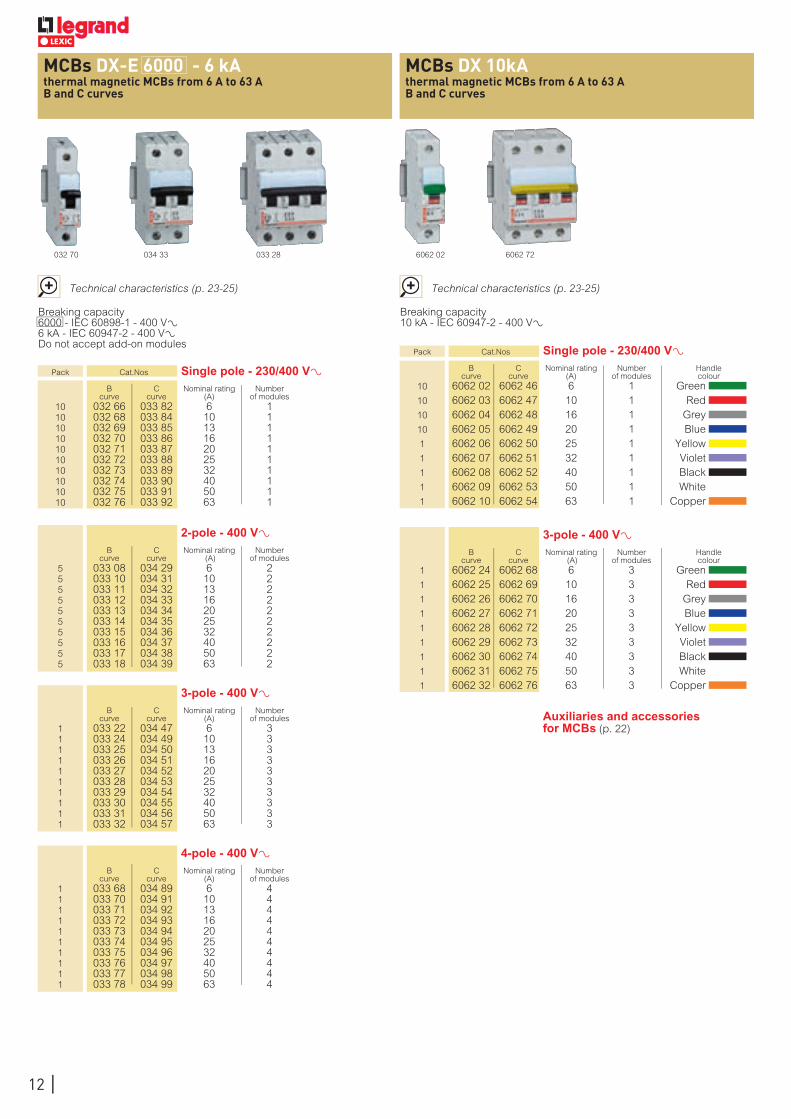
MCBs DX-E 6000 - 6 kAthermal magnetic MCBs from 6 A to 63 AB and C curves
MCBs DX 10kAthermal magnetic MCBs from 6 A to 63 AB and C curves
033 28034 33 6062 72
Breaking capacity 6000 - IEC 60898-1 - 400 VA 6 kA - IEC 60947-2 - 400 VA Do not accept add-on modules
Breaking capacity 10 kA - IEC 60947-2 - 400 VA
Pack Cat.Nos Single pole - 230/400 V± B C Nominal rating Number curve curve (A) of modules 10 032 66 033 82 6 1 10 032 68 033 84 10 1 10 032 69 033 85 13 1 10 032 70 033 86 16 1 10 032 71 033 87 20 1 10 032 72 033 88 25 1 10 032 73 033 89 32 1 10 032 74 033 90 40 1 10 032 75 033 91 50 1 10 032 76 033 92 63 1
Pack Cat.Nos Single pole - 230/400 V± B C Nominal rating Number Handle curve curve (A) of modules colour 10 6062 02 6062 46 6 1 Green 10 6062 03 6062 47 10 1 Red 10 6062 04 6062 48 16 1 Grey 10 6062 05 6062 49 20 1 Blue 1 6062 06 6062 50 25 1 Yellow 1 6062 07 6062 51 32 1 Violet 1 6062 08 6062 52 40 1 Black 1 6062 09 6062 53 50 1 White 1 6062 10 6062 54 63 1 Copper
2-pole - 400 V± B C Nominal rating Number curve curve (A) of modules 5 033 08 034 29 6 2 5 033 10 034 31 10 2 5 033 11 034 32 13 2 5 033 12 034 33 16 2 5 033 13 034 34 20 2 5 033 14 034 35 25 2 5 033 15 034 36 32 2 5 033 16 034 37 40 2 5 033 17 034 38 50 2 5 033 18 034 39 63 2
3-pole - 400 V± B C Nominal rating Number Handle curve curve (A) of modules colour 1 6062 24 6062 68 6 3 Green 1 6062 25 6062 69 10 3 Red 1 6062 26 6062 70 16 3 Grey 1 6062 27 6062 71 20 3 Blue 1 6062 28 6062 72 25 3 Yellow 1 6062 29 6062 73 32 3 Violet 1 6062 30 6062 74 40 3 Black 1 6062 31 6062 75 50 3 White 1 6062 32 6062 76 63 3 Copper
3-pole - 400 V± B C Nominal rating Number curve curve (A) of modules 1 033 22 034 47 6 3 1 033 24 034 49 10 3 1 033 25 034 50 13 3 1 033 26 034 51 16 3 1 033 27 034 52 20 3 1 033 28 034 53 25 3 1 033 29 034 54 32 3 1 033 30 034 55 40 3 1 033 31 034 56 50 3 1 033 32 034 57 63 3
4-pole - 400 V± B C Nominal rating Number curve curve (A) of modules 1 033 68 034 89 6 4 1 033 70 034 91 10 4 1 033 71 034 92 13 4 1 033 72 034 93 16 4 1 033 73 034 94 20 4 1 033 74 034 95 25 4 1 033 75 034 96 32 4 1 033 76 034 97 40 4 1 033 77 034 98 50 4 1 033 78 034 99 63 4
Technical characteristics (p. 23-25) Technical characteristics (p. 23-25)
032 70 6062 02
12
Auxiliaries and accessories for MCBs (p. 22)
073 61 023 58
Pack Cat.Nos Remote trip head isolating switches
Red handle (main device) Visible contact indication Remote tripping with associated control auxiliary Compatible with the following auxiliaries: - Control auxil. Cat.No 073 60/61/65/66/68/69 (p. 154) - Signalling auxil. Cat.No 073 50/54 (p. 154) Visual indication of the actual status of the contacts: - Closed position or fault (red indicator - I) - Open position (green indicator) on handle In case of fault when opening, the red position indicator indicates the faulty pole and the handle is in the central position
2P - 400 V± Nominal Number rating (A) of modules 2 023 56 40 2 2 023 57 63 2 2 023 58 100 2 2 023 59 125 2
3P - 400 V± 1 023 66 40 3 1 023 67 63 3 1 023 68 100 3 1 023 69 125 3
4P - 400 V± 1 023 76 40 4 1 023 77 63 4 1 023 78 100 4 1 023 79 125 4
043 26
Pack Cat.Nos Isolating switches
Can be equipped with 1 signalling auxiliary Cat.Nos 073 50 or 073 54 (p. 154)
1P - 250 V± Nominal Number rating (A) of modules 10 043 01 16 1 10 043 02 20 1 10 043 05 32 1 10 043 07 40 1 10 043 10 63 1 10 043 14 100 1
1P with indicator - 250 V± Supplied with lamp
10 043 03 20 1
2P - 400 V± 10 043 21 16 1 10 043 22 20 1 10 043 25 32 1 5 043 27 40 2 5 043 30 63 2 5 043 34 100 2 5 043 38 125 2
2P with indicator - 250 V± Supplied with lamp
10 043 23 20 1 10 043 26 32 1
3P - 400 V± 5 043 42 20 2 5 043 45 32 2 3 043 47 40 3 3 043 50 63 3 3 043 54 100 3 3 043 58 125 3
4P - 400 V± 5 043 62 20 2 5 043 65 32 2 2 043 67 40 4 2 043 70 63 4 2 043 74 100 4 2 043 78 125 4
Technical characteristics (p. 23-25) Technical characteristics (p. 23-25)
For three-phase version, please consult us
043 74023 66
AC 22 A according to IEC 60947 - 3 Double break contacts
AC 22 A according to IEC 60947 - 3 Double break contacts
043 22
remote trip isolating switches DXTM - ISfrom 16 A to 125 A
isolating switches DXTM - ISfrom 16 A to 125 A
13
14
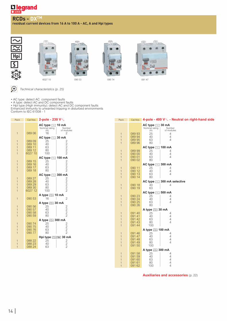
RCDs - DXTM
residual current devices from 16 A to 100 A - AC, A and Hpi types
Technical characteristics (p. 25)
090 53 090 746027 10
• AC type: detect AC component faults• A type: detect AC and DC component faults• Hpi type (High immunity): detect AC and DC component faultsEnhanced immunity to unwanted tripping in disturbed environmentsConform to IEC 61008 - 1
Pack Cat.Nos 2-pole - 230 V± AC type ? 10 mA Nominal rating Number
(A) of modules 1 089 06 16 2
AC type ? 30 mA 1 089 09 25 2 1 089 10 40 2 1 089 11 63 2 1 089 12 80 2 1 6027 10 100 2
AC type ? 100 mA 1 089 15 25 2 1 089 16 40 2 1 089 17 63 2 1 089 18 80 2
AC type ? 300 mA 1 089 27 25 2 1 089 28 40 2 1 089 29 63 2 1 089 30 80 2 1 6027 12 100 2
A type M 10 mA 1 090 53 16 2
A type M 30 mA 1 090 56 25 2 1 090 57 40 2 1 090 58 63 2 1 090 59 80 2
A type M 300 mA 1 090 74 25 2 1 090 75 40 2 1 090 76 63 2 1 090 77 80 2
Hpi type MH 30 mA 1 088 22 25 2 1 088 23 40 2 1 088 24 63 2
Pack Cat.Nos 4-pole - 400 V± - Neutral on right-hand side
AC type ? 30 mA Nominal rating Number
(A) of modules
1 089 93 25 4 1 089 94 40 4 1 089 95 63 4 1 089 96 80
AC type ? 100 mA 1 089 99 25 4 1 090 00 40 4 1 090 01 63 4 1 090 02 80
AC type ? 300 mA 1 090 11 25 4 1 090 12 40 4 1 090 13 63 4 1 090 14 80
AC type ? 300 mA selective 1 090 18 40 4 1 090 19 63
AC type ? 500 mA 1 090 23 25 4 1 090 24 40 4 1 090 25 63 4 1 090 26 80
A type M 30 mA 1 091 40 25 4 1 091 41 40 4 1 091 42 63 4 1 091 43 80 4 1 091 44 100
A type M 100 mA 1 091 46 25 4 1 091 47 40 4 1 091 48 63 4 1 091 49 80 4 1 091 50 100
A type M 300 mA 1 091 58 25 4 1 091 59 40 4 1 091 60 63 4 1 091 61 80 4 1 091 62 100 4
091 47
Auxiliaries and accessories (p. 22)

15
DXTM- IS isolating switches and DXTM-RCDstechnical characteristics
RCDs - DXTM
residual current devices from 25 A to 100 A - AC, A and Hpi types (continued)
Technical characteristics (p. 25)
086 95
• AC type: detect AC component faults• A type: detect AC and DC component faults• Hpi type (High immunity): detect AC and DC component faultsEnhanced immunity to unwanted tripping in disturbed environmentsConform to IEC 61008 - 1
4-pole - 400 V± - Neutral on left-hand side
AC type ? 30 mA Nominal rating Number
(A) of modules
1 086 93 25 4 1 086 94 40 4 1 086 95 63 4
A type M 30 mA 1 090 98 25 4 1 090 99 40 4 1 091 00 63 4
Pack Cat.Nos 4-pole - 400 V± - Neutral on right-hand side (continued)
A type M 300 mA selective Nominal rating Number
(A) of modules 1 091 65 40 4 1 091 66 63 4
A type M 500 mA 1 091 71 40 4 1 091 72 63 4 1 091 74 100 4
Hpi type MH 30 mA 1 6021 08 25 4 1 6021 09 40 4 1 6021 10 63 4
n AC type ? - Standard applications
AC type RCDs detect AC residual currents In the majority of cases (standard applications), they are used for AC current detection at 50/60 Hz
n A type M - Specific applications: dedicated lines
In addition to the characteristics of AC type RCDs, A type RCDs also detect DC residual currentsThey are used whenever fault currents are not sinusoidalThey are particularly suitable for the following specific applications (hobs, washing machines…) or materials may produce DC fault currents, speed drives with frequency inverters, etc.
n Hpi type M H - Special applications
Type Hpi RCDs are devices which offer additional immunity to unwanted tripping which significantly exceeds the level required by the standardThey are also able to detect AC and DC residual currents (A type)Operation between - 25 °C and + 40 °CThey are used in special applications where:• Loss of information is potentially damaging, e.g. power supply lines for computer equipment (banks, equipment on military bases, flight reservation centres, etc.)• Loss of operation is potentially damaging (automated machinery, medical equipment, freezer cable, etc.)They are also used:• On sites where there is an increased risk of lightning strikes (see p. 164) • On sites where cables are subject to high levels of interference (use of fluorescents, etc.)• On sites where very long cables are used
n DX - IS isolating switches
Electrical characteristics
Thermal rating (Ith) 16 - 32 A 40 - 63 A 100 - 125 A
Connection
flexible 1.5 to 16 mm2 1.5 to 25 mm2 6 to 35 mm2
rigid 1.5 to 35 mm2 4 to 50 mm2
Insulation voltage (Hi) 250 - 400 V± 250 - 400 V± 250 - 400 V±
Impulse withstand voltage (Uimp)
4 kV 4 kV 4 kV
Category of use(1) AC 22 A AC 22 A AC 22 A AC 23 A AC 23 A AC 23 A
Short time withstand current (Icw)
750 A 1700 A 2500 A
Short-circuit making capacity (Icm)
1500 A 3000 A 3700 A
No. of electrical operations > 30000 > 30000 > 30000
Protection index IP 2X IP 2X IP 2X wired wired (> 25 mm2)
(1) test conditions according to IEC 60947-3 AC 22 A: combined motor/resistor breaking AC 23 A: inductive motor breaking at In/2
n DX - RCDs (residual circuit devices)
Connection cross-section
RCDs Cable (mm2)
rigid flexible
Connection at top and bottom 50 35

16
MCBs DXTM 6000 - 10 kAthermal magnetic MCBs from 0.5 A to 63 AB and C curves
064 91
Breaking capacity 6000 - IEC 60898-1 - 400 VA (230 VA for single pole + neutral) 10 kA - IEC 60947-2 - 400 VA (230 VA for single pole + neutral)
Pack Cat.Nos Single pole - 230/400 V± Nominal Number of Breaking capacity B C rating modules IEC 60947-2 (kA) curve curve (A) 230 V± 1 061 52 063 68 1 1 10 1 061 53 063 69 2 1 10 1 061 54 063 70 3 1 10 1 061 55 063 71 4 1 10 10|1 061 56 063 72 6 1 10 10 061 58 063 74 10 1 10 10 061 60 063 76 16 1 10 10|1 061 61 063 77 20 1 10 10|1 061 62 063 78 25 1 10 10|1 061 63 063 79 32 1 10 1 061 64 063 80 40 1 10 1 061 65 063 81 50 1 10 1 061 66 063 82 63 1 10
Single pole + neutral - 230 V± Neutral on right-hand side
Nominal Number of Breaking capacity B C rating modules IEC 60947-2 (kA) curve curve (A) 230 V± 1 064 01 0.5 1 10 1 064 03 1 1 10 1 061 95 064 04 2 1 10 1 061 96 064 05 3 1 10 1 061 97 064 06 4 1 10 1 061 98 064 07 6 1 10 10 062 00 064 09 10 1 10 10 062 02 064 12 16 1 10 1 062 03 064 13 20 1 10 1 062 04 064 14 25 1 10 1 062 05 064 15 32 1 10 1 062 06 064 16 40 1 10
3-pole + neutral - 400 V± Neutral on right-hand side
Nominal Number of Breaking capacity B C rating modules IEC 60947-2 (kA) curve curve (A) 400 V± 230 V± 1 063 31 065 39 6 4 10 25 1 063 34 065 41 10 4 10 25 1 063 36 065 43 16 4 10 25 1 063 37 065 44 20 4 10 25 1 063 38 065 45 25 4 10 25 1 063 39 065 46 32 4 10 25 1 063 40 065 47 40 4 10 25 1 063 41 065 48 50 4 10 25 1 063 42 065 49 63 4 10 25
2-pole - 230/400 V± Nominal Number of Breaking capacity B C rating modules IEC 60947-2 (kA) curve curve (A) 400 V± 230 V± 1 062 57 064 60 1 2 10 25 1 062 58 064 61 2 2 10 25 1 062 59 064 62 3 2 10 25 1 062 60 064 63 4 2 10 25 1|5 062 61 064 64 6 2 10 25 5 062 63 064 66 10 2 10 25 5 062 65 064 68 16 2 10 25 1|5 062 66 064 69 20 2 10 25 1 062 67 064 70 25 2 10 25 1 062 68 064 71 32 2 10 25 1 062 69 064 72 40 2 10 25 1 062 70 064 73 50 2 10 25 1 062 71 064 74 63 2 10 25
Technical characteristics (p. 23-25)
Pack Cat.Nos 3-pole - 400 V± Nominal Number of Breaking capacity B C rating modules IEC 60947-2 (kA) curve curve (A) 400 V± 230 V± 1 064 80 1 3 10 25 1 062 78 064 81 2 3 10 25 1 062 79 064 82 3 3 10 25 1 062 80 064 83 4 3 10 25 1 062 81 064 84 6 3 10 25 1 062 83 064 86 10 3 10 25 1 062 85 064 88 16 3 10 25 1 062 86 064 89 20 3 10 25 1 062 87 064 90 25 3 10 25 1 062 88 064 91 32 3 10 25 1 062 89 064 92 40 3 10 25 1 062 90 064 93 50 3 10 25 1 062 91 064 94 63 3 10 25
4-pole - 400 V± Nominal Number of Breaking capacity C rating modules IEC 60947-2 (kA) curve (A) 400 V± 230 V± 1 065 55 1 4 10 25 1 065 56 2 4 10 25 1 065 57 3 4 10 25 1 065 58 4 4 10 25 1 065 59 6 4 10 25 1 065 61 10 4 10 25 1 065 63 16 4 10 25 1 065 64 20 4 10 25 1 065 65 25 4 10 25 1 065 66 32 4 10 25 1 065 67 40 4 10 25 1 065 68 50 4 10 25 1 065 69 63 4 10 25
065 66062 02 064 68063 72 063 38
Add-on modules (p. 20)
Auxiliaries and accessories (p. 22)
17
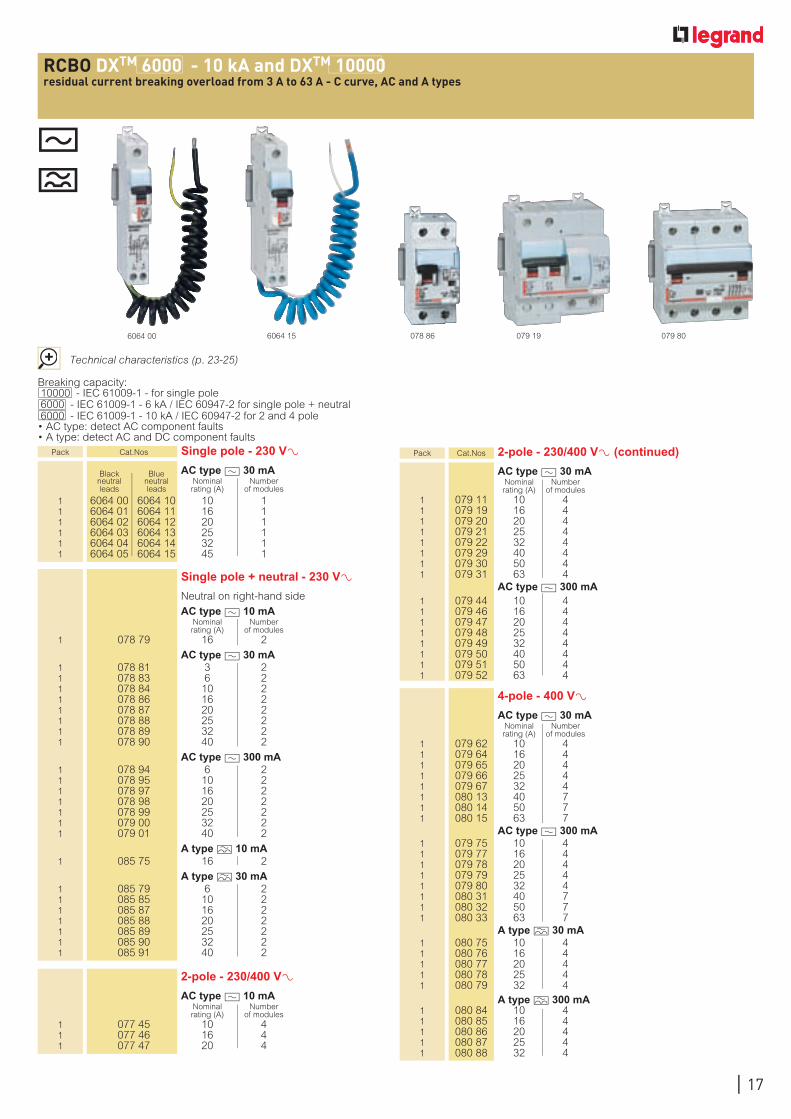
RCBO DXTM 6000 - 10 kA and DXTM 10000residual current breaking overload from 3 A to 63 A - C curve, AC and A types
Breaking capacity: 10000 - IEC 61009-1 - for single pole 6000 - IEC 61009-1 - 6 kA / IEC 60947-2 for single pole + neutral 6000 - IEC 61009-1 - 10 kA / IEC 60947-2 for 2 and 4 pole • AC type: detect AC component faults • A type: detect AC and DC component faults
Technical characteristics (p. 23-25)
Single pole + neutral - 230 V± Neutral on right-hand side
AC type ? 10 mA Nominal Number
rating (A) of modules 1 078 79 16 2
AC type ? 30 mA 1 078 81 3 2 1 078 83 6 2 1 078 84 10 2 1 078 86 16 2 1 078 87 20 2 1 078 88 25 2 1 078 89 32 2 1 078 90 40 2
AC type ? 300 mA 1 078 94 6 2 1 078 95 10 2 1 078 97 16 2 1 078 98 20 2 1 078 99 25 2 1 079 00 32 2 1 079 01 40 2
A type M 10 mA 1 085 75 16 2
A type M 30 mA 1 085 79 6 2 1 085 85 10 2 1 085 87 16 2 1 085 88 20 2 1 085 89 25 2 1 085 90 32 2 1 085 91 40 2
Pack Cat.Nos 2-pole - 230/400 V± (continued)
AC type ? 30 mA Nominal Number rating (A) of modules
1 079 11 10 4 1 079 19 16 4 1 079 20 20 4 1 079 21 25 4 1 079 22 32 4 1 079 29 40 4 1 079 30 50 4 1 079 31 63 4 AC type ? 300 mA 1 079 44 10 4 1 079 46 16 4 1 079 47 20 4 1 079 48 25 4 1 079 49 32 4 1 079 50 40 4 1 079 51 50 4 1 079 52 63 4
2-pole - 230/400 V± AC type ? 10 mA
Nominal Number rating (A) of modules
1 077 45 10 4 1 077 46 16 4 1 077 47 20 4
4-pole - 400 V± AC type ? 30 mA
Nominal Number rating (A) of modules
1 079 62 10 4 1 079 64 16 4 1 079 65 20 4 1 079 66 25 4 1 079 67 32 4 1 080 13 40 7 1 080 14 50 7 1 080 15 63 7 AC type ? 300 mA 1 079 75 10 4 1 079 77 16 4 1 079 78 20 4 1 079 79 25 4 1 079 80 32 4 1 080 31 40 7 1 080 32 50 7 1 080 33 63 7 A type M 30 mA 1 080 75 10 4 1 080 76 16 4 1 080 77 20 4 1 080 78 25 4 1 080 79 32 4 A type M 300 mA 1 080 84 10 4 1 080 85 16 4 1 080 86 20 4 1 080 87 25 4 1 080 88 32 4
078 866064 15 079 19 079 806064 00
Pack Cat.Nos Single pole - 230 V± Black Blue AC type ? 30 mA neutral neutral Nominal Number leads leads rating (A) of modules
1 6064 00 6064 10 10 1 1 6064 01 6064 11 16 1 1 6064 02 6064 12 20 1 1 6064 03 6064 13 25 1 1 6064 04 6064 14 32 1 1 6064 05 6064 15 45 1

18
MCBs DX-H 10000 - 25 kAthermal magnetic, high breaking capacity MCBs from 2 A to 125 A C curve
069 20 064 76 070 00069 43
Pack Cat.Nos Single pole - 230/400 V± Nominal Number Breaking capacity (kA) C rating of IEC 60947-2 curve (A) modules 230 V/400 V± 1 068 53 2 1 25 1 068 54 3 1 25 1 068 56 6 1 25 1 068 58 10 1 25 1 068 59 13 1 25 1 068 60 16 1 25 1 068 61 20 1 25 1 068 62 25 1 20 1 068 63 32 1 15 1 068 64 40 1 12.5 1 068 65 50 1 12.5 1 068 66 63 1 12.5 1 063 83 80 1.5 12.5 1 063 84 100 1.5 12.5 1 063 85 125 1.5 12.5
2-pole - 230/400 V± Nominal Number Breaking capacity (kA) C rating of IEC 60947-2 curve (A) modules 400 V± 230 V± 1 069 13 2 2 30 50 1 069 14 3 2 30 50 1 069 16 6 2 30 50 1 069 18 10 2 30 50 1 069 19 13 2 30 50 1 069 20 16 2 30 50 1 069 21 20 2 30 50 1 069 22 25 2 25 50 1 069 23 32 2 20 50 1 069 24 40 2 20 50 1 069 25 50 2 15 25 1 069 26 63 2 15 25 1 064 75 80 3 16 25 1 064 76 100 3 16 25 1 064 77 125 3 16 25
Pack Cat.Nos 3-pole - 400 V± Nominal Number Breaking capacity (kA) C rating of IEC 60947-2 curve (A) modules 400 V± 230 V± 1 069 33 2 3 25 50 1 069 34 3 3 25 50 1 069 36 6 3 25 50 1 069 38 10 3 25 50 1 069 39 13 3 25 50 1 069 40 16 3 25 50 1 069 41 20 3 25 50 1 069 42 25 3 20 50 1 069 43 32 3 15 50 1 069 44 40 3 15 50 1 069 45 50 3 12.5 25 1 069 46 63 3 12.5 25 1 064 95 80 4.5 12.5 16 1 064 96 100 4.5 12.5 16 1 064 97 125 4.5 12.5 16
4-pole - 400 V± Nominal Number Breaking capacity (kA) C rating of IEC 60947-2 curve (A) modules 400 V± 230 V± 1 069 93 2 4 25 50 1 069 94 3 4 25 50 1 069 96 6 4 25 50 1 069 98 10 4 25 50 1 069 99 13 4 25 50 1 070 00 16 4 25 50 1 070 01 20 4 25 50 1 070 02 25 4 20 50 1 070 03 32 4 15 50 1 070 04 40 4 15 50 1 070 05 50 4 12.5 25 1 070 06 63 4 12.5 25 1 065 70 80 6 12.5 16 1 065 71 100 6 12.5 16 1 065 72 125 6 12.5 16
Technical characteristics (p. 23-25)
Single pole + neutral - 230 V± Neutral on right-hand side Nominal Number Breaking capacity (kA) C rating of IEC 60947-2 curve (A) modules 230 V± 1 068 96 6 2 25 1 068 98 10 2 25 1 068 99 13 2 25 1 069 00 16 2 25 1 069 01 20 2 25 1 069 02 25 2 20 1 069 03 32 2 15 1 069 04 40 2 15 1 069 05 50 2 12.5 1 069 06 63 2 12.5
3-pole + neutral - 400 V± Neutral on right-hand side Nominal Number Breaking capacity (kA) C rating of IEC 60947-2 curve (A) modules 400 V± 230 V± 1 069 76 6 4 25 50 1 069 78 10 4 25 50 1 069 79 13 4 25 50 1 069 80 16 4 25 50 1 069 81 20 4 25 50 1 069 82 25 4 20 50 1 069 83 32 4 15 50 1 069 84 40 4 15 50 1 069 85 50 4 12.5 25 1 069 86 63 4 12.5 25
068 60
Breaking capacity10000 IEC 60898-1 - 400 VA 25 kA to 12.5 kA - IEC 60947-2 - 400 VA
B and Z curve, please consult us
Add-on modules (p. 20)
Auxiliaries and accessories (p. 22)
19
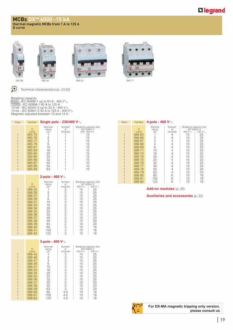
MCBs DXTM 6000 -15 kAthermal magnetic MCBs from 1 A to 125 AD curve
Breaking capacity6000 - IEC 60898-1 up to 63 A - 400 VA10000 - IEC 60898-1 80 A to 125 A 15 kA - IEC 60947-2 up to 32 A - 400 VA 10 kA - IEC 60947-2 40 A to 125 A - 400 VA Magnetic adjusted between 10 and 14 In
Pack Cat.Nos Single pole - 230/400 V± Nominal Number Breaking capacity (kA) D rating of IEC 60947-2 curve (A) modules 230 - 400 V± 1 065 75 1 1 15 1 065 76 2 1 15 1 065 77 3 1 15 1 065 79 6 1 15 1 065 81 10 1 15 1 065 83 16 1 15 1 065 84 20 1 15 1 065 85 25 1 15 1 065 86 32 1 15 1 065 87 40 1 10 1 065 88 50 1 10 1 065 89 63 1 10
2-pole - 400 V± Nominal Number Breaking capacity (kA) D rating of IEC 60947-2 curve (A) modules 400 V± 230 V± 1 066 25 1 2 15 25 1 066 26 2 2 15 25 1 066 27 3 2 15 25 1 066 29 6 2 15 25 1 066 31 10 2 15 25 1 066 33 16 2 15 25 1 066 34 20 2 15 25 1 066 35 25 2 15 25 1 066 36 32 2 15 25 1 066 37 40 2 10 20 1 066 38 50 2 10 20 1 066 39 63 2 10 20 1 066 40 80 3 10 16 1 066 41 100 3 10 16 1 066 42 125 3 10 16
Pack Cat.Nos 4-pole - 400 V± Nominal Number Breaking capacity (kA) D rating of IEC 60947-2 curve (A) modules 400 V± 230 V± 1 066 65 1 4 15 25 1 066 66 2 4 15 25 1 066 67 3 4 15 25 1 066 68 4 4 15 25 1 066 69 6 4 15 25 1 066 71 10 4 15 25 1 066 73 16 4 15 25 1 066 74 20 4 15 25 1 066 75 25 4 15 25 1 066 76 32 4 15 25 1 066 77 40 4 10 20 1 066 78 50 4 10 20 1 066 79 63 4 10 20 1 066 80 80 6 10 16 1 066 81 100 6 10 16 1 066 82 125 6 10 16
3-pole - 400 V± Nominal Number Breaking capacity (kA) D rating of IEC 60947-2 curve (A) modules 400 V± 230 V± 1 066 45 1 3 15 25 1 066 46 2 3 15 25 1 066 47 3 3 15 25 1 066 49 6 3 15 25 1 066 51 10 3 15 25 1 066 53 16 3 15 25 1 066 54 20 3 15 25 1 066 55 25 3 15 25 1 066 56 32 3 15 25 1 066 57 40 3 10 20 1 066 58 50 3 10 20 1 066 59 63 3 10 20 1 066 60 80 4.5 10 16 1 066 61 100 4.5 10 16 1 066 62 125 4.5 10 16
066 36 066 62 066 71065 89
Technical characteristics (p. 23-25)
For DX-MA magnetic tripping only version, please consult us
Add-on modules (p. 20)
Auxiliaries and accessories (p. 22)
20
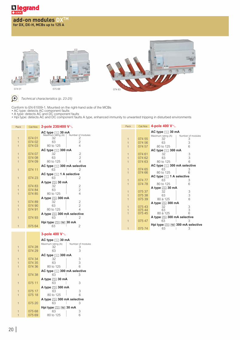
add-on modules DXTM
for DX, DX-H, MCBs up to 125 A
Pack Cat.Nos 2-pole 230/400 V± AC type ? 30 mA
Maximum rating (A) Number of modules 1 074 01 32 2 1 074 02 63 2 1 074 03 80 to 125 4 AC type ? 300 mA 1 074 07 32 2 1 074 08 63 2 1 074 09 80 to 125 4 AC type ? 300 mA selective 1 074 11 63 2 AC type ? 1 A selective 1 074 23 63 2 A type M 30 mA 1 074 83 32 2 1 074 84 63 2 1 074 85 80 to 125 4 A type M 300 mA 1 074 89 32 2 1 074 90 63 2 1 074 91 80 to 125 4 A type M 300 mA selective 1 074 93 63 2
Hpi type M H 30 mA 1 075 64 63 2
Pack Cat.Nos 4-pole 400 V± AC type ? 30 mA Maximum rating (A) Number of modules 1 074 55 32 3 1 074 56 63 3 1 074 57 80 to 125 6 AC type ? 300 mA 1 074 61 32 3 1 074 62 63 3 1 074 63 80 to 125 6 AC type ? 300 mA selective 1 074 65 63 3 1 074 66 80 to 125 6 AC type ? 1 A selective 1 074 77 63 3 1 074 78 80 to 125 6 A type M 30 mA 1 075 37 32 3 1 075 38 63 3 1 075 39 80 à 125 6 A type M 300 mA 1 075 43 32 3 1 075 44 63 3 1 075 45 80 à 125 6 A type M 300 mA selective 1 075 47 63 3 Hpi type M H 300 mA selective 1 075 74 63 3
Conform to EN 61009-1. Mounted on the right-hand side of the MCBs• AC type: detects AC component faults• A type: detects AC and DC component faults• Hpi type: detects AC and DC component faults A type, enhanced immunity to unwanted tripping in disturbed environments
3-pole 400 V± AC type ? 30 mA Maximum rating (A) Number of modules 1 074 28 32 3 1 074 29 63 3 AC type ? 300 mA 1 074 34 32 3 1 074 35 63 3 1 074 36 80 to 125 6 AC type ? 300 mA selective 1 074 38 63 3 A type M 30 mA 1 075 11 63 3 A type M 300 mA 1 075 17 63 3 1 075 18 80 to 125 6 A type M 300 mA selective 1 075 20 63 3 Hpi type M H 30 mA 1 075 68 63 3 1 075 69 80 to 125 6
Technical characteristics (p. 23-25)
074 01 074 63075 68
21
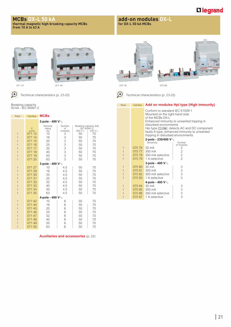
add-on modules DX-Lfor DX-L 50 kA MCBs
MCBs DX-L 50 kAthermal magnetic high breaking capacity MCBs from 10 A to 63 A
Breaking capacity 50 kA - IEC 60947-2
Pack Cat.Nos MCBs
2-pole - 400 V± Nominal Number Breaking capacity (kA) C rating of IEC 60947-2 curve (A) modules 400 V± 230 V± 1 071 12 10 3 50 70 1 071 14 16 3 50 70 1 071 15 20 3 50 70 1 071 16 25 3 50 70 1 071 17 32 3 50 70 1 071 18 40 3 50 70 1 071 19 50 3 50 70 1 071 20 63 3 50 70
3-pole - 400 V± 1 071 27 10 4.5 50 70 1 071 29 16 4.5 50 70 1 071 30 20 4.5 50 70 1 071 31 25 4.5 50 70 1 071 32 32 4.5 50 70 1 071 33 40 4.5 50 70 1 071 34 50 4.5 50 70 1 071 35 63 4.5 50 70
4-pole - 400 V± 1 071 42 10 6 50 70 1 071 44 16 6 50 70 1 071 45 20 6 50 70 1 071 46 25 6 50 70 1 071 47 32 6 50 70 1 071 48 40 6 50 70 1 071 49 50 6 50 70 1 071 50 63 6 50 70
071 44 075 85071 14 075 76
Technical characteristics (p. 23-25) Technical characteristics (p. 23-25)
Pack Cat.Nos Add on modules Hpi type (High immunity)
Conform to standard IEC 61009-1 Mounted on the right-hand side of the MCBs DX-L Enhanced immunity to unwanted tripping in disturbed environments Hpi type MH: detects AC and DC component faults A type, enhanced immunity to unwanted tripping in disturbed environments
2-pole - 230/400 V± Sensitivity Number
of modules 1 075 76 30 mA 2 1 075 77 300 mA 2 1 075 78 300 mA selective 2 1 075 79 1 A selective 2
3-pole - 400 V± 1 075 80 30 mA 3 1 075 81 300 mA 3 1 075 82 300 mA selective 3 1 075 83 1 A selective 3
4-pole - 400 V± 1 075 84 30 mA 3 1 075 85 300 mA 3 1 075 86 300 mA selective 3 1 075 87 1 A selective 3
Auxiliaries and accessories (p. 22)
22Bold pack quantities : Minimum quantities to be ordered
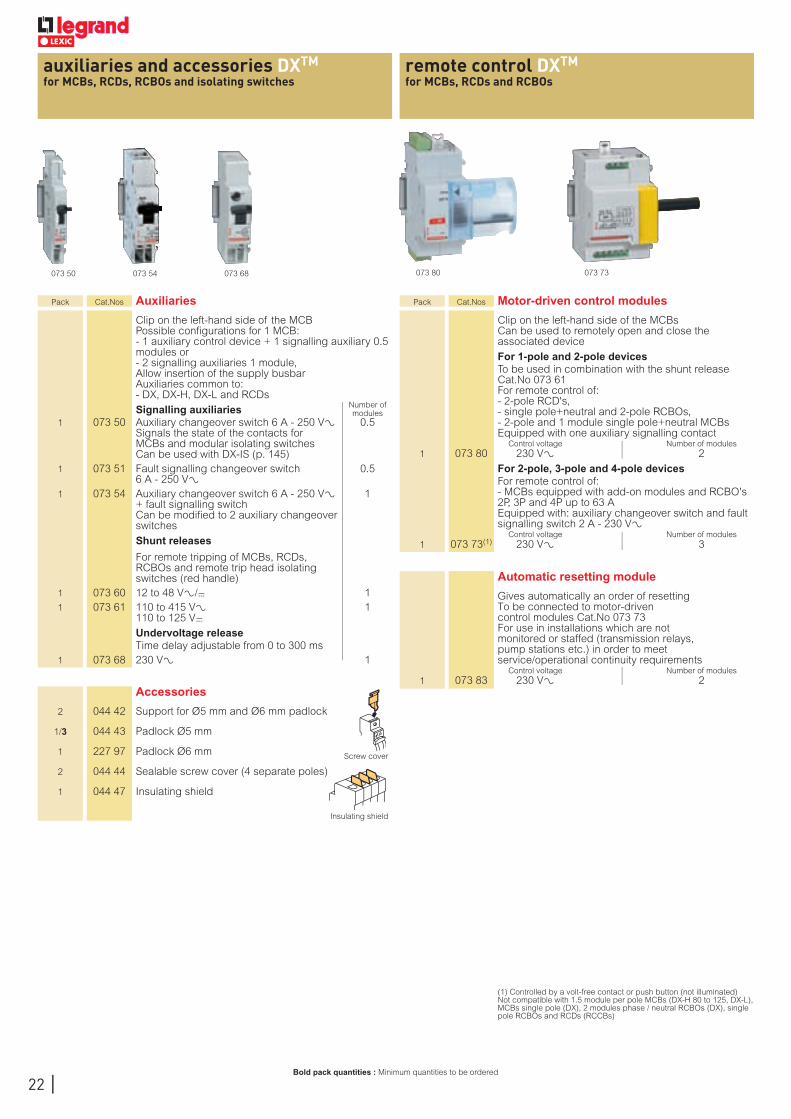
remote control DXTM
for MCBs, RCDs and RCBOsauxiliaries and accessories DXTM
for MCBs, RCDs, RCBOs and isolating switches
073 80073 50 073 54 073 68 073 73
Pack Cat.Nos Auxiliaries
Clip on the left-hand side of the MCB Possible configurations for 1 MCB: - 1 auxiliary control device + 1 signalling auxiliary 0.5 modules or - 2 signalling auxiliaries 1 module, Allow insertion of the supply busbar Auxiliaries common to: - DX, DX-H, DX-L and RCDs
Number of Signalling auxiliaries modules 1 073 50 Auxiliary changeover switch 6 A - 250 V± 0.5
Signals the state of the contacts for MCBs and modular isolating switches Can be used with DX-IS (p. 145)
1 073 51 Fault signalling changeover switch 0.5 6 A - 250 V±
1 073 54 Auxiliary changeover switch 6 A - 250 V± 1 + fault signalling switch Can be modified to 2 auxiliary changeover switches
Shunt releases
For remote tripping of MCBs, RCDs, RCBOs and remote trip head isolating switches (red handle)
1 073 60 12 to 48 V±/= 1 1 073 61 110 to 415 V± 1 110 to 125 V= Undervoltage release Time delay adjustable from 0 to 300 ms 1 073 68 230 V± 1
Pack Cat.Nos Motor-driven control modules
Clip on the left-hand side of the MCBs Can be used to remotely open and close the associated device
For 1-pole and 2-pole devices To be used in combination with the shunt release
Cat.No 073 61 For remote control of: - 2-pole RCD's, - single pole+neutral and 2-pole RCBOs, - 2-pole and 1 module single pole+neutral MCBs Equipped with one auxiliary signalling contact
Control voltage Number of modules 1 073 80 230 V± 2
For 2-pole, 3-pole and 4-pole devices For remote control of:
- MCBs equipped with add-on modules and RCBO's 2P, 3P and 4P up to 63 A Equipped with: auxiliary changeover switch and fault signalling switch 2 A - 230 V±
Control voltage Number of modules 1 073 73(1) 230 V± 3
Automatic resetting module
Gives automatically an order of resetting To be connected to motor-driven control modules Cat.No 073 73 For use in installations which are not monitored or staffed (transmission relays, pump stations etc.) in order to meet service/operational continuity requirements
Control voltage Number of modules 1 073 83 230 V± 2
(1) Controlled by a volt-free contact or push button (not illuminated) Not compatible with 1.5 module per pole MCBs (DX-H 80 to 125, DX-L), MCBs single pole (DX), 2 modules phase / neutral RCBOs (DX), single pole RCBOs and RCDs (RCCBs)
Accessories
2 044 42 Support for Ø5 mm and Ø6 mm padlock
1/3 044 43 Padlock Ø5 mm
1 227 97 Padlock Ø6 mm Screw cover
2 044 44 Sealable screw cover (4 separate poles)
1 044 47 Insulating shield
Insulating shield
23
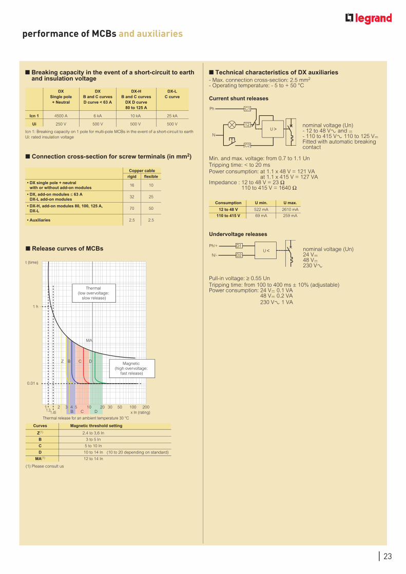
performance of MCBs and auxiliaries
Icn 1: Breaking capacity on 1 pole for multi-pole MCBs in the event of a short-circuit to earthUi: rated insulation voltage
n Breaking capacity in the event of a short-circuit to earth and insulation voltage
DX DX DX-H DX-L
Single pole B and C curves B and C curves C curve + Neutral D curve < 63 A DX D curve 80 to 125 A
Icn 1 4500 A 6 kA 10 kA 25 kA
Ui 250 V 500 V 500 V 500 V
n Connection cross-section for screw terminals (in mm2)
n Release curves of MCBs
Curves Magnetic threshold setting
Z(1) 2.4 to 3,6 In
B 3 to 5 In
C 5 to 10 In
D 10 to 14 In (10 to 20 depending on standard)
MA(1) 12 to 14 In
n Technical characteristics of DX auxiliaries- Max. connection cross-section: 2.5 mm2
- Operating temperature: - 5 to + 50 °C
Current shunt releases
Min. and max. voltage: from 0.7 to 1.1 UnTripping time: < to 20 msPower consumption: at 1.1 x 48 V = 121 VA
at 1.1 x 415 V = 127 VAImpedance : 12 to 48 V = 23 Ω
110 to 415 V = 1640 Ω
nominal voltage (Un)- 12 to 48 V± and =- 110 to 415 V± 110 to 125 V= Fitted with automatic breaking contact
Consumption U min. U max.
12 to 48 V 522 mA 2610 mA
110 to 415 V 69 mA 259 mA
(1) Please consult us
Copper cablerigid flexible
• DX single pole + neutral with or without add-on modules
16 10
• DX, add-on modules ≤ 63 A DX-L add-on modules
32 25
• DX-H, add-on modules 80, 100, 125 A, DX-L
70 50
• Auxiliaries 2.5 2.5
Undervoltage releases
Pull-in voltage: ≥ 0.55 UnTripping time: from 100 to 400 ms ± 10% (adjustable)Power consumption: 24 V= 0.1 VA 48 V= 0.2 VA 230 VA 1 VA
nominal voltage (Un)24 V=48 V=230 V±
11.31.45
3 4 5 10 20 30 50 100 200x In (rating)
Thermal release for an ambient temperature 30 °C
Magnetic (high overvoltage:
fast release)
CB
DCB
Z
Thermal (low overvoltage:
slow release)
2
0.01 s
1 h
t (time)
MA
D
C1
12
C2
U
Ph
N
D1
D2U
Ph/+
N/-
24
performance of MCBs and auxiliaries (continued)
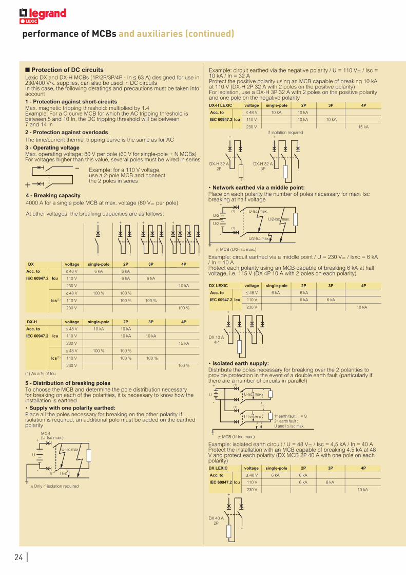
n Protection of DC circuitsLexic DX and DX-H MCBs (1P/2P/3P/4P - In ≤ 63 A) designed for use in 230/400 V± supplies, can also be used in DC circuitsIn this case, the following deratings and precautions must be taken into account
1 - Protection against short-circuitsMax. magnetic tripping threshold: multiplied by 1.4Example: For a C curve MCB for which the AC tripping threshold is between 5 and 10 In, the DC tripping threshold will be between 7 and 14 In
2 - Protection against overloadsThe time/current thermal tripping curve is the same as for AC
3 - Operating voltageMax. operating voltage: 80 V per pole (60 V for single-pole + N MCBs)For voltages higher than this value, several poles must be wired in series
Example: for a 110 V voltage, use a 2-pole MCB and connect the 2 poles in series
DX voltage single-pole 2P 3P 4P
Acc. to ≤ 48 V 6 kA 6 kA
IEC 60947.2 Icu 110 V 6 kA 6 kA
230 V 10 kA
≤ 48 V 100 % 100 %
Ics(1) 110 V 100 % 100 %
230 V 100 %
DX-H voltage single-pole 2P 3P 4P
Acc. to ≤ 48 V 10 kA 10 kA
IEC 60947.2 Icu 110 V 10 kA 10 kA
230 V 15 kA
≤ 48 V 100 % 100 %
Ics(1) 110 V 100 % 100 %
230 V 100 %
Example: circuit earthed via the negative polarity / U = 110 V= / Isc = 10 kA / In = 32 AProtect the positive polarity using an MCB capable of breaking 10 kA at 110 V (DX-H 2P 32 A with 2 poles on the positive polarity)For isolation, use a DX-H 3P 32 A with 2 poles on the positive polarity and one pole on the negative polarity
+
-
+
-
+
-
+
-
DX-H LEXIC voltage single-pole 2P 3P 4P
Acc. to ≤ 48 V 10 kA 10 kA
IEC 60947.2 Icu 110 V 10 kA 10 kA
230 V 15 kA
DX LEXIC voltage single-pole 2P 3P 4P
Acc. to ≤ 48 V 6 kA 6 kA
IEC 60947.2 Icu 110 V 6 kA 6 kA
230 V 10 kA
DX LEXIC voltage single-pole 2P 3P 4P
Acc. to ≤ 48 V 6 kA 6 kA
IEC 60947.2 Icu 110 V 6 kA 6 kA
230 V 10 kA
5 - Distribution of breaking polesTo choose the MCB and determine the pole distribution necessary for breaking on each of the polarities, it is necessary to know how the installation is earthed• Supply with one polarity earthed:Place all the poles necessary for breaking on the other polarity If isolation is required, an additional pole must be added on the earthed polarity
• Network earthed via a middle point:Place on each polarity the number of poles necessary for max. Isc breaking at half voltage
Example: circuit earthed via a middle point / U = 230 V= / Isxc = 6 kA / In = 10 A Protect each polarity using an MCB capable of breaking 6 kA at half voltage, i.e. 115 V (DX 4P 10 A with 2 poles on each polarity)
• Isolated earth supply:Distribute the poles necessary for breaking over the 2 polarities to provide protection in the event of a double earth fault (particularly if there are a number of circuits in parallel)
Example: isolated earth circuit / U = 48 V= / Isc = 4,5 kA / In = 40 AProtect the installation with an MCB capable of breaking 4.5 kA at 48 V and protect each polarity (DX MCB 2P 40 A with one pole on each polarity)
(1) As a % of Icu
(1) Only if isolation required
MCB (U-Isc max.)
U U-Isc max
U=0 (1)
+
-
DX-H 32 A 2P
DX-H 32 A 3P
If isolation required + +
-
-
(1) MCB (U/2-Isc max.)
(1)
(1)
U/2
U/2
U-Isc max.
U/2-Isc max.
U/2-Isc max.
+
-
+
-
DX 10 A 4P
U-Isc max.
U-Isc max. 1st earth fault : I = O 2sd earth fault : U and I Isc max.
U
+
-
(1) MCB (U-Isc max.)
(1)
(1)
DX 40 A 2P
+
-
4 - Breaking capacity4000 A for a single pole MCB at max. voltage (80 V= per pole)
At other voltages, the breaking capacities are as follows:

Add-on modules - DX 6000 , DX-H, D curve 6000 A
- DX-L 30000 A
RCBOs
- P + N 3000 A
- 2P (4 modules) 6000 A
- 4P 10 to 32 A (4 modules) 4500 A
- 4P 40 to 63 A (7 modules) 6000 A
Downstream RCD
Upstream cartridge fuse gG Upstream MCB
≤ 40 A 63 A 80 A 100 ADX (B/C) DX-H (B/C)
DX-L DPX 1251P+N 2,3,4P ≤ 63 A 80 < 125 A
2P/ 4P
16 A 100 kA 50 kA 15 kA 10 kA 6 kA 10 kA 20 kA(1) 12.5 kA 50 kA 25 kA
25 A 100 kA 50 kA 15 kA 10 kA 6 kA 10 kA 20 kA(1) 12.5 kA 50 kA 25 kA
40 A 100 kA 50 kA 15 kA 10 kA 6 kA 10 kA 15 kA(1) 12.5 kA 50 kA 25 kA
63 A 100 kA 50 kA 15 kA 10 kA 10 kA12.5 kA(1) 12.5 kA 50 kA 25 kA
80 A 100 kA 50 kA 15 kA 10 kA12.5 kA(1) 12.5 kA 25 kA
100 A 100 kA 50 kA 15 kA 10 kA12.5 kA(1) 12.5 kA 25 kA
n RCD tripping curves• Average RCD operating curves
n 2P and 4P RCDs: withstand to short-circuits
Caution: it is advisable to provide overload protection for the RCD
n DX RCBOs residual current breaking capacityI∆m according to EN 61009-1
For more information on the basic rules of protection, come and be trained at Innoval www.legrand.com
n Specific case of continuity of service
In certain locations, where there are no personnel, in which particular care is required to ensure continuity of service, false tripping of MCBs is not permissible (isolated telephone/TV/radio relay stations, pumping stations, etc.)
The combination of an Hpi type RCBO with motor-driven control and a recloser provides optimum continuity of service (p. 155)
(1) Same nominal rating for both, MCB and RCD
10 410 310 210 110 0
0.01
0.05
0.1
0.5
10mA 30mA 300mA 1A
t(s)
I (mA)
1
A, AC or Hpitype selective (s)
A or AC type instantaneous
Hpi type
Motor-driven controlCat.No 073 73
Automatic reclosing control device Cat.No 073 83

World Headquarters and International Department128, av. du Maréchal-de-Lattre-de Tassigny87045 Limoges Cedex - France%: + 33 (0) 5 55 06 87 87
www.legrand.com
EXB
102
48 -
Nov
embe
r 20
11