white paper the right sensors for every application · the right sensors for every application a...
TRANSCRIPT

WHITE PAPER
The right sensors for every application
A comparison of optical and magnetic length and angular measurement systems
The requirements of length and angular measurement procedures are highly varied, and consequently a
broad product spectrum has emerged in recent years. By clarifying certain key data at an early stage,
however, the selection of an appropriate system is made considerably simpler. Using application
examples, drawings and images, this white paper offers a clear comparison of the advantages and
disadvantages of optical and magnetic sensors. It helps to guide the reader in selecting a tailored system
that considers both economic and technological aspects in equal measure.

2
CONTENTS
1 Introduction ....................................................................................................................... 3
2 Main considerations for the initial selection of a suitable length measurement process ... 5
3 Optical measurement systems – high precision and insensitivity to magnetic influences. 6
3.1 Advantages of optical systems .................................................................................. 7
3.2 Disadvantages of optical systems .............................................................................. 8
3.3 Applications ideally suited to optical measurement systems ..................................... 9
4 Magnetic measurement systems: economically viable and simple to work with ............. 14
4.1 Advantages of magnetic tape length measurement systems .................................. 16
4.2 Disadvantages of magnetic measurement systems ................................................ 16
4.3 Applications of magnetic measurement systems ..................................................... 18
5 Special features of rotary systems .................................................................................. 26
6 The Siko MagLine product family: magnetic length and angle measurement systems... 27
6.1 MagLine Micro ......................................................................................................... 27
6.2 MagLine Basic ......................................................................................................... 29
6.3 MagLine Macro ........................................................................................................ 30
6.4 MagLine Roto ........................................................................................................... 31
7 OptoLine: optical sensors from Siko ............................................................................... 32
8 Conclusion ...................................................................................................................... 33
List of Illustrations ................................................................................................................... 35

3
1 Introduction
Precise length measurement is a fundamental requirement in industrial production. Yet the
specifications of the measurement systems are as varied as the fields of application in which
the sensors are used. While it may be necessary to measure distances of up to a hundred
meters in cold conditions in a warehouse logistics setting, the biggest challenge faced in
mechanical engineering is sufficient precision. Furthermore, contamination caused by
ambient media often hampers the measurement process: in a woodworking environment, for
example, sensors have to function reliably in spite of high exposure to dust. When used in
wet-processing with CNC-controlled milling machines, sensors are constantly exposed to
lubricoolants. The function of the measurement systems, or in other words, the reliability of
the measurement results, must not be allowed to suffer because of impurities such as swarf
or chips flying about, for example.
The capacity of the measurement system to function even under harsh environmental
conditions, together with its precision and the economic viability of the system, is one of the
main arguments for selecting the appropriate measurement technology. Owing to this
diversity of requirements, in recent years a wide product spectrum has been developed. In
technological terms, magnetic sensors border on the level of precision of optical systems.
There are nevertheless certain applications that demand such high precision that only optical
systems can be considered. Compared to magnetic systems, however, these are more
sensitive to external influences such as dust or fluids. Encapsulating the sensors can help
protect them, say, from harmful emulsions in a CNC milling environment. This is however a
costly undertaking.
4
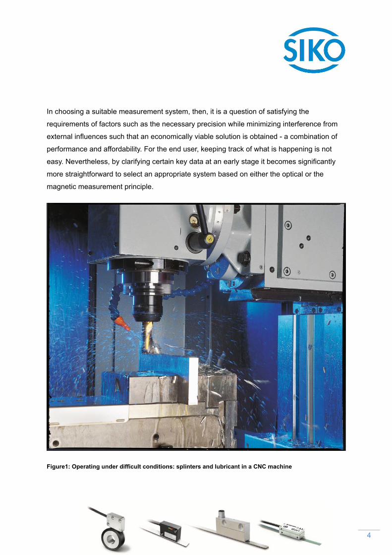
In choosing a suitable measurement system, then, it is a question of satisfying the
requirements of factors such as the necessary precision while minimizing interference from
external influences such that an economically viable solution is obtained - a combination of
performance and affordability. For the end user, keeping track of what is happening is not
easy. Nevertheless, by clarifying certain key data at an early stage it becomes significantly
more straightforward to select an appropriate system based on either the optical or the
magnetic measurement principle.
Figure1: Operating under difficult conditions: splinters and lubricant in a CNC machine

5
2 Main considerations for the initial selection of a suitable length measurement
process
When selecting an appropriate length measurement process the following factors should be
considered first: the higher the required precision, the more important it will be to use an
optical measurement process. As regards the operational environment, however, the
following basic principle applies: the greater the contamination of the operational
environment through dust and liquids, the more obvious are the benefits of magnetic
solutions. In the experience of Uwe Frey from the MagLine technical sales team at Black
Forest-based measurement technology manufacturer SIKO GmbH, the required precision of
the measurement is the key factor when it comes to finding suitable sensors: “The most
decisive factor is the level of precision required. If the customer wishes to measure an area
with a precision tolerance of ± 5 micrometers, then there is little doubt that an optical system
should be used. As for magnetic sensors, these can offer precision of up to ± 10
micrometers.”
However, he also points out how much has changed in the field of magnetic systems in the
past. “Even just a few years ago, values less that ± 25 micrometers were unheard of in
magnetic systems. For high-precision applications there was no choice but to use optical
processes.” The smaller pole pitch of the measuring strips that can be obtained using
modern production techniques has meanwhile enabled the accuracy of magnetic
measurement processes to be greatly improved.
Since 1963 Siko has established itself as a provider of measurement technology for various
tasks such as length, angle and rotational speed measurement and for the measurement of
inclination and speed. The Black Forest-based company’s extensive portfolio of magnetic
sensors is completed with a range of optical sensors offering exceptional levels of precision.

6
The ‘MagLine’ range of magnetic length and angle measurement products has been steadily
developed in recent years. The highest level of system and repeatability are obtained in the
MagLine Micro product line. The MSK1000 digital magnetic sensor, for example, can output
resolutions of down to 0.2 micrometers (200 nanometers) and offers a repeatability of ±1
micrometer. The magnetic tapes are produced in-house with great care and using high-
precision equipment. The manufacturer has developed a special process for coding the
measurement tapes. Depending whether the measurement process required is incremental
or absolute, one or more magnetic code tracks is attached. Recent product developments
have also proved remarkable in terms of repeatability and the axis speeds that can be
achieved.
The optical LSC20 sensor and the optical TS20 measuring tape are used to capture lengths
and angles using optical principles. This high-precision measurement system can reliably
record measuring steps even at high traverse speeds (3 m/s and 1.5 m/s respectively). The
TS20 optical rule can be used both as a length measurement system for up to 30 meters
length and also as an angle measurement system for measurements below 360 degrees.
3 Optical measurement systems – high precision and insensitivity to magnetic
influences
SIKO OptoLine optical systems evaluate information on an optical measuring tape using a
laser-based technology. The positional values are forwarded to the downstream electronics
as digital counter pulses (A, B, R). The technique makes use of the Talbot effect: Light is
distributed at defined spacings in the pattern of a grating. A grating structure is also created
behind the sensor head. This grating is now irradiated with monochrome waves, such that a
wider light distribution is obtained behind it. This technique allows a comparatively large
distance between the sensor and the optical rule. With this technology the sensor head can
be made very small. For applications in which dimension is a critical factor, this method is
ideal.

7
Fig. 2: Basic structure of an optical measuring tape
3.1 Advantages of optical systems
The precision of the LSC20 optical sensor is very high and lies in the range of about ± 5
micrometers. Compared to the magnetic system with its precision of ±10 micrometers, this
represents a doubling in precision. On top of this, the resolution of 0.05 micrometers is
greater by a factor of 4 than the 0.2 micrometers currently offered by magnetic systems.
Another advantage of the optical system is its insensitivity to magnetic disturbances. Where
linear motors are used, for example, electromagnetic interference can occur in the form of
stray magnetic fields that can falsify the position values of a magnetic sensor. Yet linear
motors are one of the main areas of application for magnetic sensors at Siko – especially
where the motors are used under harsh ambient conditions. This is because the stray
magnetic effect of the linear motors is only critical if the sensor head and magnetic tape are
positioned too close to the motor. If the user maintains a defined safety clearance between
the sensor and the motor or fits a shield, interference can be avoided. The further the motor
is from the sensor, the less it affects the sensors. Accordingly, the real benefit of optical
sensors becomes evident in situations where space is restricted or very powerful magnetic
fields are present. For purely physical reasons, in magnetic systems a hysteresis effect
arises in relation to the measured values. No such effect occurs in optical systems since they
are not prone to electromagnetic influences.
8
3.2 Disadvantages of optical systems
By contrast to magnetic systems, optical systems are sensitive to environmental factors such
as dust, swarf, oil and grease. In harsh conditions protection is also required for the
measurement system against shock and vibration stresses and dirt. The measurement
technology is also affected by temperature fluctuations and high air humidity; any formation
of condensation on the code strips can result in measurement errors. To avoid this, elaborate
housings can be created for protection against the influences described above, but these
force the costs of the measurement system upward.
In terms of cost, optical sensors are generally more expensive than magnetic sensors.
Optical incremental sensors cost, for the same quantity, roughly twice as much as magnetic
sensors. The same is true for the rules: the cost of magnetic tapes is two to two and a half
times less than that of optical tapes. A further disadvantage of optical measurement
technology is the installation and handling by technical personnel. When sensors are
mounted, their mechanical tolerances are dependent on the guide to which they are
attached. An optical sensor must be adjusted precisely if the mechanical tolerances are to be
offset. The sensors must always be moved exactly equally over the rule in order to obtain
accurate values consistently. Dust and dirt must not be allowed to affect the sensor even
during installation; measures must be taken to prevent this occurring.
9
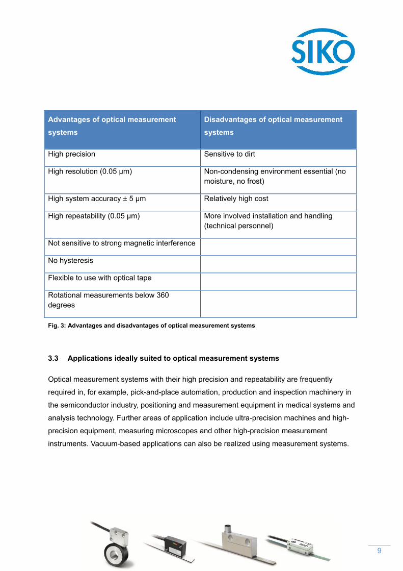
Advantages of optical measurement
systems
Disadvantages of optical measurement
systems
High precision Sensitive to dirt
High resolution (0.05 µm) Non-condensing environment essential (no moisture, no frost)
High system accuracy ± 5 µm Relatively high cost
High repeatability (0.05 µm) More involved installation and handling (technical personnel)
Not sensitive to strong magnetic interference
No hysteresis
Flexible to use with optical tape
Rotational measurements below 360 degrees
Fig. 3: Advantages and disadvantages of optical measurement systems
3.3 Applications ideally suited to optical measurement systems
Optical measurement systems with their high precision and repeatability are frequently
required in, for example, pick-and-place automation, production and inspection machinery in
the semiconductor industry, positioning and measurement equipment in medical systems and
analysis technology. Further areas of application include ultra-precision machines and high-
precision equipment, measuring microscopes and other high-precision measurement
instruments. Vacuum-based applications can also be realized using measurement systems.

10
Example applications include:
Pick-and-place automation
High precision is required for automated component placement on printed circuit boards.
Individual components such as resistors, capacitors and integrated circuits must be
positioned exactly on the PCB before they are soldered in place. The exact positional
measurement is provided by optical sensors.
Fig. 4: Compact optical sensors are ideal for capturing positional information in pick-and-place systems.

11
Semiconductor technology
Optical sensors are used in manufacturing and inspection machines in the semiconductor
industry. In clean room conditions the contacts used for chips may be gold or aluminum.
Such chips, or integrated circuits, may have their functional electronic components integrated
just 1 micrometer below the surface. This then is a process that calls for absolute precision -
using optical sensors that are 100% hysteresis-free.
Fig. 5: Wire Bonder Image credit: Wire Bonder – stock image, istockphoto.com, dolah

12
Medical and analysis systems
In analysis systems, optical sensors are used in areas such as liquid handling. Pipetting
robots are used to collect, transport and dispense liquids from sample stocks in very small
and precise quantities and at high speed. A position that has been left must be returned to
next time with only the smallest deviation. Since the samples are placed very closely side by
side, the pipetting system must be designed to high precision requirements and with high
repeatability. Optical systems are ideal for these situations.
Fig. 6: Path and angle measurement for medical and analysis applications: pipette automation

13
Linear drive systems
Linear motors are used wherever fast movements must be performed with high reliability.
Optical sensors are fitted directly to the motor in order to measure its movements. The tape
used in the optical system has very compact dimensions, and the optical sensor head itself
also has a small form factor. It is thus easy to integrate optical sensors into the drive unit.
Fig. 7: Optical sensors provide accurate feedback on linear motors

14
4 Magnetic measurement systems: economically viable and simple to work with
In magnetic measurement systems the sensor travels along a flexible magnetic tape without
touching it. The actual magnetic tape is mounted on a 0.3 millimeter thick layer of bearing
steel. Magnetization takes place using defined pole pitches. A signal is generated when the
magnetic pole is scanned. This is converted into digital square-wave signals, which can then
be processed by downstream electronics. The sensors recognize the pitch of the tape and
convert the information into high-resolution path information. No direct contact is required in
order to read the magnetic field lines. The MSK5000 magnetic sensor, for example, allows a
distance of up to 2 millimeters to the measuring surface.
Fig. 8: Schematic illustration of the functioning of a magnetic measurement system
15
Incremental coding provides robust and cost-efficient all-round solutions. In an incremental
technique the magnetic tape is magnetized into north and south poles at equal spacings. As
the sensor moves over the tape, path information is sent in the form of squarewave signals.
The distance covered can then be determined exactly in terms of the number of segments
passed through. For the incremental measurement method it is normally necessary to set an
absolute reference point. All paths detected are then relative to this defined reference point.
This is particularly important where the system is re-energized after a phase without power.
Without the magnetic coding of the reference point, fine adjustment must be carried out
again in such cases by means of a reference run.
Where the magnetization of the tape is unchanged, such so-called quasi-absolute
techniques allow the necessity for reference runs to be minimized. This method uses the
principle of incremental position measurement. The electronics nevertheless buffers the data
using an integrated battery. The reference system is thus retained even when the machine is
switched off. Moreover, the use of lowest-power technology allows dependable operation
over long periods of time. The sensors can be used for up to ten years without a battery
change.
However, if the customer is prepared to invest in a somewhat more cost-intensive system, a
system based on absolute measurement data can be used: No reference point is required
in such systems since the magnetic coding defines unique positional values at every point on
the tape. The absolute codings of the magnetic tapes increase measurement reliability, since
when they are fitted with appropriate absolute sensors such as the Siko MSA111C they allow
positions to be determined even when there is no power. After power outages, for example if
the system has been disconnected and reconnected, the true positional value is recorded
and converted even if the sensor position has been altered in the meantime. Depending on
the design of the machine, this can be of considerable relevance to safety.

16
4.1 Advantages of magnetic tape length measurement systems
While optical systems are not longer than 30 meters, magnetic systems are available for up
to 100 meters. As a rule, applications of this kind, such as warehouse logistics, do not call for
extreme levels of precision. Far more important in such situations are mechanical resilience
and insensitivity to environmental influences. Magnetic sensors are resistant to dirt, oil and
moisture and relatively robust when exposed to shock and vibration. They thus offer the user
a wide range of possible applications, such as for plant and equipment used out of doors or
on machine tools. Another advantage of the magnetic tape is its flexibility of handling; the
user can place the tape in stock as rolled goods and configure it himself.
As well as linear measurement, magnetic measurement systems can be used for rotational
measurements of angles greater than 360 degrees (see Section 5: Special features of
rotational systems).
4.2 Disadvantages of magnetic measurement systems
Compared to optical systems, magnetic systems generally have lower levels of absolute
precision, resolution and repeatability. A magnetic field such as is present in a magnetic
sensor can be detrimentally influenced by external ferromagnetic interference. This sensitivity
to stray magnetic fields can reduce measurement accuracy. It may be noted that the
disadvantages of magnetic measurement technology concerning measurement accuracy and
ferromagnetic interference explain the advantages of optical measurement principles.

17
Advantages of magnetic measurement
systems
Disadvantages of magnetic measurement
systems
Not sensitive to dirt, oil or moisture Lower precision
Wide range of applications Lower resolution
Price advantage Lower repeatability
Can be used at temperatures down to -40 °C Sensitive to stray magnetic fields
Relatively insensitive to shock and vibration
Not affected by condensation
No need for physical encapsulation
Up to 20 mm reading distance
Flexibility in handling of magnetic tape
Can measure rotations greater than 360 degrees
Fig. 9: Advantages and disadvantages of magnetic measurement systems compared to optical systems

18
4.3 Applications of magnetic measurement systems
Magnetic measurement technology is robust and is used for contactless path and angular
position measurement. The fields of application of magnetic sensors are many, covering all
areas of mechanical engineering and industrial automation. They are used, for example, in
linear and rotational drive systems (direct drive systems and motor feedback), in production
machinery for furniture and parquet flooring and even in high-tech medical applications such
as computer tomography. They are also suitable for extreme applications such as stone
processing and glass machining. Magnetic sensors have also proven themselves particularly
effective for the mirror tracking systems of solar power collectors and in stage technology, in
forklift trucks and in waste and scrap compaction equipment.
Example applications include:
Woodworking
Wherever planing takes place, shavings are created – and this is always so in woodworking.
The sensitivity of magnetic systems to such conditions is a crucial factor. Dust, shavings and
aggressive lubricants from the machine can be harmful to sensors. Magnetic measurement
technology is wholly resistant to these elements, while meeting all the requirements for
precision. In industrial parquet manufacturing, an accurate and fast machine is used to
ensure a high-quality end product. The parquet panels must fit together without gaps.

19
The requirements for precision when milling to the individual dimensions and the different
profiles of the panels are fulfilled entirely by a magnetic sensor system.
Fig. 10: Autarkic electronic length stop for circular panel saws Picture credits: Wilhelm Altendorf GmbH & Co. KG
20
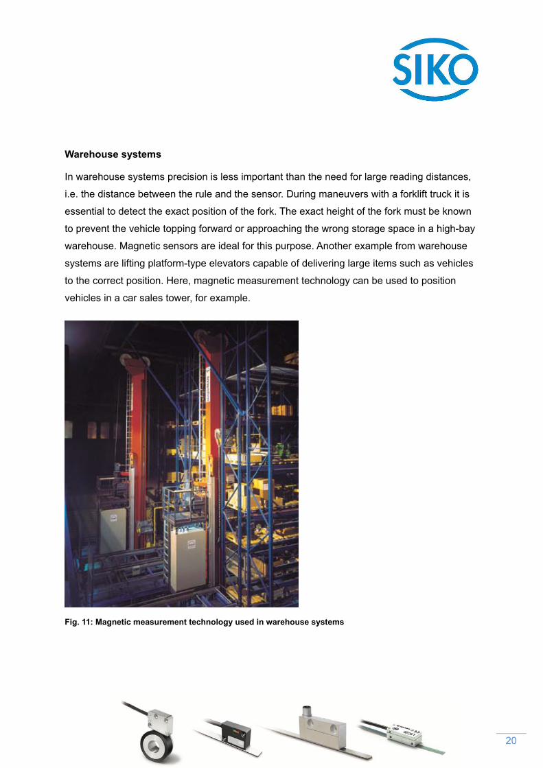
Warehouse systems
In warehouse systems precision is less important than the need for large reading distances,
i.e. the distance between the rule and the sensor. During maneuvers with a forklift truck it is
essential to detect the exact position of the fork. The exact height of the fork must be known
to prevent the vehicle topping forward or approaching the wrong storage space in a high-bay
warehouse. Magnetic sensors are ideal for this purpose. Another example from warehouse
systems are lifting platform-type elevators capable of delivering large items such as vehicles
to the correct position. Here, magnetic measurement technology can be used to position
vehicles in a car sales tower, for example.
Fig. 11: Magnetic measurement technology used in warehouse systems
21
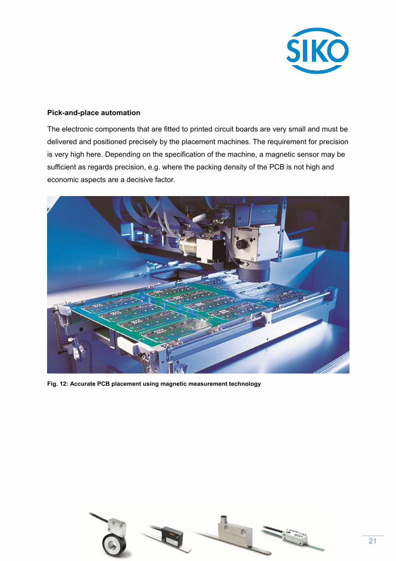
Pick-and-place automation
The electronic components that are fitted to printed circuit boards are very small and must be
delivered and positioned precisely by the placement machines. The requirement for precision
is very high here. Depending on the specification of the machine, a magnetic sensor may be
sufficient as regards precision, e.g. where the packing density of the PCB is not high and
economic aspects are a decisive factor.
Fig. 12: Accurate PCB placement using magnetic measurement technology
22
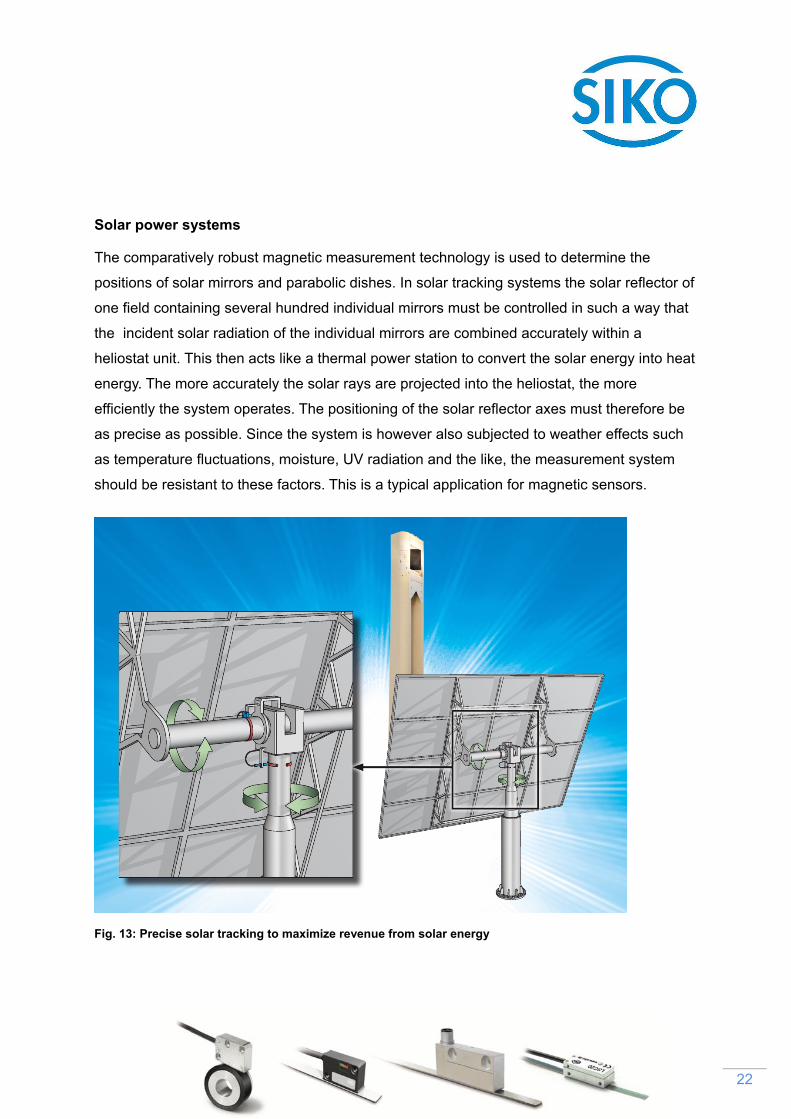
Solar power systems
The comparatively robust magnetic measurement technology is used to determine the
positions of solar mirrors and parabolic dishes. In solar tracking systems the solar reflector of
one field containing several hundred individual mirrors must be controlled in such a way that
the incident solar radiation of the individual mirrors are combined accurately within a
heliostat unit. This then acts like a thermal power station to convert the solar energy into heat
energy. The more accurately the solar rays are projected into the heliostat, the more
efficiently the system operates. The positioning of the solar reflector axes must therefore be
as precise as possible. Since the system is however also subjected to weather effects such
as temperature fluctuations, moisture, UV radiation and the like, the measurement system
should be resistant to these factors. This is a typical application for magnetic sensors.
Fig. 13: Precise solar tracking to maximize revenue from solar energy
23
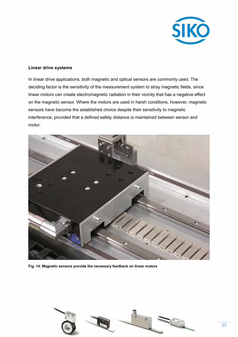
Linear drive systems
In linear drive applications, both magnetic and optical sensors are commonly used. The
deciding factor is the sensitivity of the measurement system to stray magnetic fields, since
linear motors can create electromagnetic radiation in their vicinity that has a negative effect
on the magnetic sensor. Where the motors are used in harsh conditions, however, magnetic
sensors have become the established choice despite their sensitivity to magnetic
interference, provided that a defined safety distance is maintained between sensor and
motor.
Fig. 14: Magnetic sensors provide the necessary feedback on linear motors

24
Medical and analysis systems
In medical and analysis systems, the choice between an optical and a magnetic
measurement system is determined by the precision level required. Magnetic technology can
thus also provide the system required for pipetting systems or centrifuge units. A magnetic
measurement system is responsible, for example, for the positioning of the patient table in a
computer tomography (CT) unit (height, inclination and position within the unit). The
measurement system also captures the position of the patient on the table, which has a
direct effect on the precision of the scan.
Fig. 15: Rotational and length measurement in a computer tomography unit

25
Digital printing
In digital printing, dimensions are normally specified in the international unit of inches. Siko
measurement technology enables the measurement system parameters to be set exactly in
this unit. Thus resolutions can be set not only in terms of metric units but also in terms of the
US customary measurement system. For many other measurement systems, this
modification entails significant extra expense in making adjustments and reprogramming.
Fig. 16: Digital printing application Image credit: Ecosolvent printer - stock image, istockphoto.com, Insanet

26
5 Special features of rotary systems
Path measurements of circular movements bring with them specific challenges. Despite the
fact that turning and swiveling are standard operations in mechanical engineering, they
nevertheless pose challenges to the designers of measurement systems that should not be
underestimated. Siko offers magnetically coded measuring tapes in the form of flexible
magnetic rings with no flange or glued with a metallic ring (flange). By attaching the tape to
the ring, joints would unavoidably occur that would cause measurement errors. To prevent
this, Siko has established its own ring production facility in which the tape is first attached
and then coded. This assures a system precision of up to ±0.01°. In addition to a portfolio of
rings in different sizes, Siko also offers custom modifications. From a certain flange diameter
upwards, Siko tapes can be fitted by the customer to allow angle measurements below 360
degrees. Where larger quantities are involved, customers also have the option of having their
own rings coded by Siko.
For magnetic sensors Siko offers ready finished measurement rings that have such a high
quality of manufacture that they can be used for measurements greater than 360 degrees. As
for optical sensors, Siko does not offer rings but rather measurement tapes that are affixed to
the flange. From a diameter of 50 mm upwards, angle functions below 360 degrees can be
measured. The handling of the tapes in rolled form is significantly more demanding in the
case of optical systems and must be performed by trained personnel with suitable
qualifications. As a consequence, while swiveling axes can be measured using optical
sensors in an open construction design, continuous rotational movements cannot. Thus
optical sensors can be used successfully with this technique to capture the cutting angle of a
saw in mitering operations, while the rotations of the shaft of an electric motor are much
more easily recorded using a magnetic system (such as a bearing-free system).

27
6 The Siko MagLine product family: magnetic length and angle measurement
systems
To help the user find his way about the product range Siko has arranged the products by
their basic specifications and applications into four product families. These are:
6.1 MagLine Micro
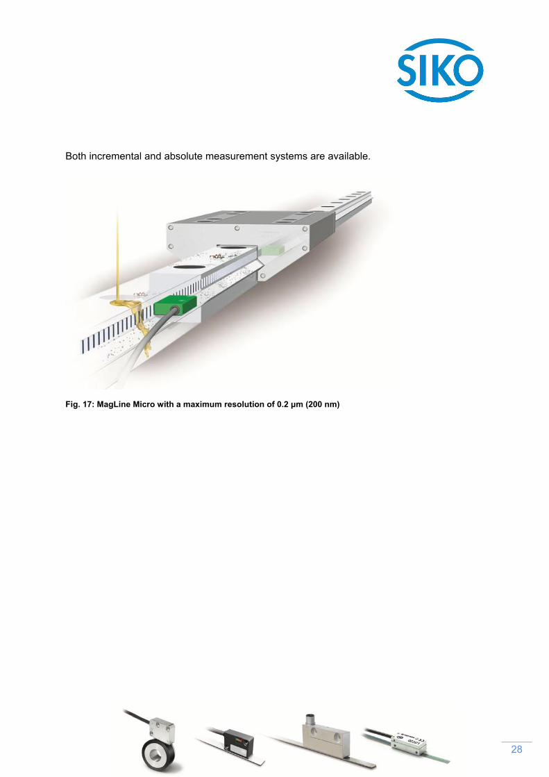
Products in the Micro family have the highest levels of system accuracy and repeatability.
They have been developed specially to meet the needs of high-precision and dynamic
processing environments. They are thus used particularly in linear and rotational guidance
and drive systems. Many applications that would traditionally involve cost-intensive glass
scale solutions can instead be equipped with this economical and flexible form of sensor
system. Compared to optical methods, magnetic sensor systems demonstrate greater
robustness and are less susceptible to interference. The precision of their measurements are
not affected by the typical effects of machines - vibrations, oscillations, shocks and so on.
When used on machine tools, robust magnetic sensors can withstand the unavoidable
contamination (with swarf, lubricants etc.) and mechanical stresses. To minimize the possible
sources of mechanical errors, no moving parts are used in the sensors. The electronics are
entirely encapsulated. Tough plastic or all-metal enclosures ensure that the sensors continue
to function correctly even when in direct contact with liquids or solids within the machine.
28
Both incremental and absolute measurement systems are available.
Fig. 17: MagLine Micro with a maximum resolution of 0.2 μm (200 nm)
29
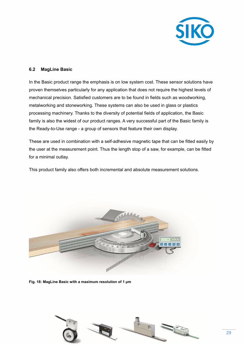
6.2 MagLine Basic
In the Basic product range the emphasis is on low system cost. These sensor solutions have
proven themselves particularly for any application that does not require the highest levels of
mechanical precision. Satisfied customers are to be found in fields such as woodworking,
metalworking and stoneworking. These systems can also be used in glass or plastics
processing machinery. Thanks to the diversity of potential fields of application, the Basic
family is also the widest of our product ranges. A very successful part of the Basic family is
the Ready-to-Use range - a group of sensors that feature their own display.
These are used in combination with a self-adhesive magnetic tape that can be fitted easily by
the user at the measurement point. Thus the length stop of a saw, for example, can be fitted
for a minimal outlay.
This product family also offers both incremental and absolute measurement solutions.
Fig. 18: MagLine Basic with a maximum resolution of 1 μm

30
6.3 MagLine Macro
The Macro family offers solutions for where long distances are to be measured. This
contactless measurement technique enables height differences, which invariably arise above
a certain measurement length, to be compensated. For the specific challenges of warehouse
and materials handling systems it is a significant advantage that reading distances can be up
to 20 mm. In stage and studio technology also, exact position measurement of the order of
millimeters together with ease of integration into control systems from various manufacturers
is a primary consideration in the purchasing decisions of many customers. In this field, the
possibility of measuring the complex interplay of multiple moving parts from a central location
to millimeter precision is particularly valued. As with its other product ranges, Siko again
places great importance on the physical robustness of its long-distance sensors. They meet
the specifications of the international protection class IP 67. This provides such high
protection from external influences that they can be used in even extreme environments such
as in stoneworking.
Fig. 19: MagLine Macro with a maximum resolution of 0.25 mm
6.4 M
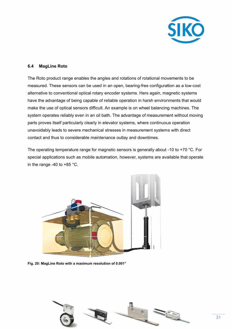
The Rot
measur
alternat
have the
make th
system
parts pr
unavoid
contact
The ope
special
in the ra
Fig. 20: M
MagLine Ro
to product r
red. These s
tive to conve
e advantag
he use of op
operates re
roves itself p
dably leads
and thus to
erating temp
applications
ange -40 to
MagLine Roto
oto
range enab
sensors can
entional opt
e of being c
ptical senso
eliably even
particularly
to severe m
o considera
perature ran
s such as m
+85 °C.
o with a maxi
les the ang
n be used in
tical rotary e
capable of r
ors difficult. A
n in an oil ba
clearly in e
mechanical
ble mainten
nge for mag
mobile autom
mum resolut
les and rota
n an open, b
encoder sys
reliable ope
An example
ath. The adv
elevator syst
stresses in
nance outla
gnetic sens
mation, how
tion of 0.001°
ations of rot
bearing-free
stems. Here
eration in ha
e is on whe
vantage of
tems, where
measurem
y and down
ors is gene
wever, syste
tational mov
e configurat
e again, ma
arsh environ
el balancing
measureme
e continuou
ent systems
ntimes.
rally about -
ems are ava
vements to
tion as a low
agnetic syst
nments that
g machines
ent without
us operation
s with direc
-10 to +70 °
ailable that
be
w-cost
tems
would
s. The
moving
n
ct
°C. For
operate
31
32
7 OptoLine: optical sensors from Siko
The Siko OptoLine product range includes the LSC20 optical incremental sensor and the
TS20 optical measuring tape. Both these devices measure lengths and angles using optical
principles. As with the MagLine product family, the OptoLine is an open measurement system
that is simple to install and requires minimal space. It can thus be flexibly integrated into
either new or existing systems.
The LSC20 optical sensing head has the following dimensions: 34.3 mm x 14.3 mm x 11.7
mm. The sensing head accommodates both the sensor and the interpolation circuitry. The
mounting tolerances of the device are very high, of the order of 1 mm +/- 0.15 mm. A three-
color adjustment LED (green, red or yellow) is fitted to the sensor head. The LED output
indicates to the user when the alignment of the optical sensor and the optical tape is correct,
even in awkward installation conditions.
Provided with the unit is a 15-pin D-sub plug for connecting on a plug-and-play basis to the
DT20 diagnosis tool. The plug contains no electronics, and so the sensor can operate without
it, even with an open cable end. The precision of the optical sensors is ± 5 µm, irrespective of
the measurement distance. The sensor signals are output in a resolution of either 0.1 or 0.05
µm; the maximum possible traverse speed depends on which of these is selected. With a
resolution of 0.1 µm, this optical sensor issues reliable signals even at 3 m/s.
The TS 20 optical tape consists of a flexible metal strip with etched microstructures of a width
of 20 µm. It has a thickness of 0.2 millimeters and a width of 6 millimeters and can be
supplied in lengths of up to 30 meters.
Operating temperatures of up to +70 °C are possible. It can be stored at temperatures in the
range -20 to +85 °C. While the optical tape is in use, the relative air humidity should be
between 10 and 90%.

33
8 Conclusion
For all fields of application the same rule of thumb applies: the greater the overall length of
the unit to be measured, the greater is the price advantage of magnetic over optical
solutions.
The market for contact-free and self-finishing measurement systems has become highly
differentiated in recent years. Modern production techniques have now made it possible to
manufacture measuring tapes for magnetic systems that have largely overcome the earlier
weaknesses of this technique. Measurement precision levels of up to ±10 micrometers mean
that these sensors can even be used in high-precision CNC machine tools. The low
susceptibility of these sensors to contamination from swarf and lubricants is a significant
advantage over the glass scales that were almost exclusively used in the past. Unlike these,
magnetic measuring tapes are available in roll form and so offer great flexibility in use.
An interesting compromise between traditional glass rules and magnetic sensor systems has
emerged in the form of configurable optical measurement systems. They can also be stored
in a warehouse and adapted to suit the object to be measured. They are significantly more
precise than the highest-resolution magnetic systems, but this accuracy comes at the cost of
increased requirements with regard to ambient conditions. Measurements can be distorted
by either heavy contamination or condensation. A major advantage of optical systems is their
lack of sensitivity to magnetism, which suits them to use in linear drive systems.
Many factors must be considered when deciding between an optical and a magnetic
measurement system. These include the absolute precision and repeatability required,
vulnerability to stray magnetic fields and to ambient conditions, and economic aspects in
terms of cost efficiency. Here a provider of measurement technology is invaluable who can
offer solutions oriented to the customer’s specific specifications and can adapt the
measurement technology to the exact requirements of the measurement task.

34
Contact:
SIKO GmbH
Weihermattenweg 2
79256 Buchenbach
www.siko-global.com
MagLine product range
Andreas Wiessler
MagLine division head
Tel.: +49 7661 394-358
E-Mail: [email protected]
OptoLine product range
Kerstin Graw
OptoLine product manager
Tel.: +49 7661 394-254
E-Mail: [email protected]
35
List of Illustrations
Figure1: Operating under difficult conditions: splinters and lubricant in a CNC machine ......... 4
Fig. 2: Basic structure of an optical measuring tape ................................................................ 7
Fig. 3: Advantages and disadvantages of optical measurement systems ................................ 9
Fig. 4: Compact optical sensors are ideal for capturing positional information in pick-and-
place systems. ........................................................................................................................ 10
Fig. 5: Wire Bonder Image credit: Wire Bonder – stock image, istockphoto.com, dolah .. 11
Fig. 6: Path & angle measurement for medical & analysis applications: pipette automation ..12
Fig. 7: Optical sensors provide accurate feedback on linear motors ...................................... 13
Fig. 8: Schematic illustration of the functioning of a magnetic measurement system ............ 14
Fig. 9: Advantages and disadvantages of magnetic measurement systems compared to
optical systems ....................................................................................................................... 17
Fig. 10: Autarkic electronic length stop for circular panel saw………………………………….
……………………………………………………..…….. Image credit: Wilhelm Altendorf GmbH & Co. KG .. 19
Fig. 11: Magnetic measurement technology used in warehouse systems ............................. 20
Fig. 12: Accurate PCB placement using magnetic measurement technology ........................ 21
Fig. 13: Precise solar tracking to maximize revenue from solar energy ................................. 22
Fig. 14: Magnetic sensors provide the necessary feedback on linear motors ........................ 23
Fig. 15: Rotational and length measurement in a computer tomography unit ........................ 24
Fig. 16: Digital printing application Image credit: Ecosolvent printer - stock image, istockphoto.com, Insanet …25
Fig. 17: MagLine Micro with a maximum resolution of 0.2 μm (200 nm) ................................ 28
Fig. 18: MagLine Basic with a maximum resolution of 1 μm .................................................. 29
Fig. 19: MagLine Macro with a maximum resolution of 0.25 mm ........................................... 30
Fig. 20: MagLine Roto with a maximum resolution of 0.001° ................................................. 31