white paper - process raman gas analysis in ammonia ... raman gas analysis in ammonia production and...
TRANSCRIPT

Reliable Precise Rapid
Authors
Scott Sutherland, Ph.D. SpectraSensors, Inc. 4333 W. Sam Houston Pkwy N. Suite 100 Houston, TX 77043
Peter van Vuuren, Ph.D. SpectraSensors, Inc. 4333 W. Sam Houston Pkwy N. Suite 100 Houston, TX 77043
Susan P. Harris Endress+Hauser 4333 W. Sam Houston Pkwy N. Suite 190 Houston, TX 77043
Travis Miller Coffeyville Resources Nitrogen Fertilizers 701 E Martin St. Coffeyville, KS 67337
Keywords
Process Raman Spectroscopy, Syngas, Laser Spectroscopy, Gasification, Hydrogen, Ammonia
Abstract
On-line process measurement of the composition of gas streams in refining, fertilizer, and other manufacturing industries is essential for the optimal operation of different process units within these facilities. Process analyzers based on gas chromatography, mass spectrometry, and electrochemical technologies are commonly used in these facilities. However, process conditions for certain streams present major challenges for these traditional technologies. Techniques based on optical spectroscopy, including near-infrared (NIR), infrared (dispersive and Fourier transform), and Raman spectroscopy, can provide analysis solutions for these challenging stream conditions. Raman spectroscopy is particularly useful for streams containing homonuclear diatomic gases, such as H2 and N2. These gases are key components in many chemical processes involving the creation and use of syngas (H2, CO, and CO2), such as the manufacturing of ammonia and methanol. Hydrogen is also an essential feedstock for the hydrotreating, hydrocracking, and catalytic reforming of various hydrocarbon fractions in refineries. A case study will be presented for the application of Raman spectroscopy to analyze syngas from the gasification of petcoke in a fertilizer plant. A second case study will be presented for the analysis of hydrogen, hydrogen sulfide and other compounds in the hydrogen recycle in a refinery hydrotreater/hydrocracker and for hydrogen purity measurements in a hydrogen plant. The discussion will include the overall importance of the measurements to plant operation, and potential cost savings for the Raman measurement technology over other, more traditional technologies. Competitive technologies will be discussed, along with lessons learned concerning the specifics of the Raman analyzer installations, and the unique safety features enabled in implementing this optical technology.
White Paper
Process Raman gas analysis in ammonia production and refining

Process Raman Gas Analysis in Ammonia Production and Refining
Page 2
Case 1: Syngas analysis in a fertilizer plant
Coffeyville Resources Nitrogen Fertilizers, LLC, owns and operates a nitrogen fertilizer facility in Coffeyville, Kansas. The plant began operation in 2000 and, as of 2017, is the only fertilizer manufacturing facility in North America using a petroleum coke (petcoke) gasification process to produce the hydrogen used in the production of nitrogenous fertilizer. The petcoke is generated at an oil refinery adjacent to the plant, which is also owned and operated by a subsidiary of CVR Energy. The petcoke is gasified to produce hydrogen-rich synthesis gas, which is converted to anhydrous ammonia (NH3), with over 96% ultimately being converted to the fertilizer, urea ammonium nitrate (UAN) and diesel exhaust fluid (DEF). In 2015, the Coffeyville facility produced 385,400 tons of ammonia and 928,600 tons of UAN solution. Recently, the facility decided to install a new process analyzer using laser-based Raman spectroscopy for the measurement of syngas, due to challenges they had with more conventional process analyzer technologies.
The Optograf™ analyzer is a process spectrometer that is based on Raman spectroscopy. At this site, the analyzer is installed within the CO sour shift reactor and heat recovery section of the plant (Figure 1). The most important and challenging stream that the analyzer is measuring is the inlet to the first CO sour shift reactor, which essentially represents the composition outlet of the entrained flow slagging gasifier quench section after the scrubbers. This stream presents challenges for analysis as it contains the highest quantity of particulates and water vapor content (as high as 60%). Currently, the composition measurement of this stream is used for monitoring, but not control, of the operation of the gasifier.
Figure 1. Coffeyville Resources process diagram (courtesy of the Coffeyville Facility).
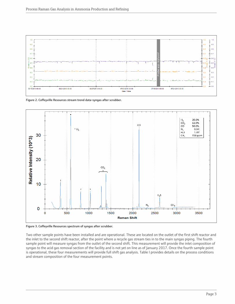
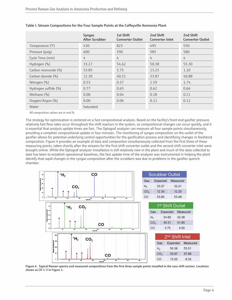
Figure 2 shows measured data for this stream over a six week period. Only the major syngas components, representing 99.4% of the stream, are shown. The gray bar near July 9, 2013 denotes where the AirHead™ probe was removed and replaced with another probe, and the results demonstrate that there was no change in the performance of the analyzer. Figure 3 shows a typical Raman spectrum (Optogram) from the Optograf analyzer, clearly showing the baseline separated peaks for all the major components of the process stream.
Air Separation Unit Coke Grinding & Slurry Preparation
MainGasifier
Syngas Scrubbing
Shift and Heat Recovery
Acid Gas Removal
Sulfur Recovery
SyngasSyngas Scrubbing
SpareGasifier
O2N2
CO2Recovery
CO2
Raw CO2
CO2 Purification
H2
Raw H2
H2S
NH3
CH 2
CH 1
CH 3
CH 4
1st CO Shift
2nd CO Shift
Pressure Swing Adsorption
UAN Plant
UAN Product
Ammonia Synthesis
AmmoniaProduct
Slurry
Process Raman Gas Analysis in Ammonia Production and Refining
Page 3
Figure 2. Coffeyville Resources stream trend data-syngas after scrubber.
Figure 3. Coffeyville Resources spectrum of syngas after scrubber.
Two other sample points have been installed and are operational. These are located on the outlet of the first shift reactor and the inlet to the second shift reactor, after the point where a recycle gas stream ties in to the main syngas piping. The fourth sample point will measure syngas from the outlet of the second shift. This measurement will provide the inlet composition of syngas to the acid gas removal section of the facility and is not yet on line as of January 2017. Once the fourth sample point is operational, these four measurements will provide full shift gas analysis. Table I provides details on the process conditions and stream composition of the four measurement points.
Process Raman Gas Analysis in Ammonia Production and Refining
Page 4
Table I. Stream Compositions for the Four Sample Points at the Coffeyville Ammonia Plant
Syngas After Scrubber
1st Shift Converter Outlet
2nd Shift Converter Inlet
2nd Shift Converter Outlet
Temperature (°F) 430 825 495 550
Pressure (psig) 600 590 585 580
Cycle Time (min) 4 4 4 4
Hydrogen (%) 33.27 54.62 50.38 55.30
Carbon monoxide (%) 53.85 3.75 13.25 1.10
Carbon dioxide (%) 12.30 40.51 33.87 40.88
Nitrogen (%) 0.53 0.37 1.59 1.74
Hydrogen sulfide (%) 0.77 0.65 0.62 0.66
Methane (%) 0.00 0.04 0.18 0.21
Oxygen/Argon (%) 0.00 0.06 0.11 0.11
Water SaturatedAll composition values are in mol.%.
The strategy for optimization is centered on a fast compositional analysis. Based on the facility’s front end gasifier pressure, relatively fast flow rates occur throughout the shift reactors in the system, so compositional changes can occur quickly, and it is essential that analysis update times are fast. The Optograf analyzer can measure all four sample points simultaneously, providing a complete compositional update in four minutes. The monitoring of syngas composition on the outlet of the gasifier allows for potential underlying control opportunities for the gasification process and identifying changes in feedstock composition. Figure 4 provides an example of data and composition simultaneously collected from the first three of these measuring points, taken shortly after the streams for the first shift converter outlet and the second shift converter inlet were brought online. While the Optograf analyzer installation is still relatively new in the plant and much of the data collected to date has been to establish operational baselines, the fast update time of the analyzer was instrumental in helping the plant identify that rapid changes in the syngas composition after the scrubbers was due to problems in the gasifier quench chamber.
Figure 4. Typical Raman spectra and measured compositions from the first three sample points installed in the sour shift section. Locations shown as CH 1-3 in Figure 1.

Process Raman Gas Analysis in Ammonia Production and Refining
Page 5
Case 2: Hydrogen analysis in a refinery
The objective of the refining process is to convert crude oil to gasoline, jet fuel, diesel oil, liquefied petroleum gas and fuel oils. There are many processes within the refinery which utilize hydrogen, including hydrotreating, hydrocracking, catalytic reforming, fluid catalytic cracking (FCC), isomerization, and alkylation. These processes vary depending on the input feed stock and the desired modification to that feedstock, such as sulfur removal, or need to produce specific end products, such as diesel oil. Hydrogen consumption by oil refineries is growing due an increase in global oil consumption, the increasing use of low quality heavy crude oil feedstocks, which requires more hydrogen to refine and due to low sulfur requirements in diesel fuels.
There are several different process units in an oil refinery that are necessary to upgrade or further refine, the primary distillate fractions derived from the Atmospheric Distillation Unit and the Vacuum Distillation Unit. In addition to crude oil and distillate fractions, the use of H2 is an important consumable used to upgrade some of the distillate fractions, primarily via hydrotreaters (removal of sulfur components) and hydrocrackers (cracking of high molecular weight fractions into smaller molecules). The H2 is either produced on site (via a hydrogen plant and catalytic reformers) or can be supplied by a 3rd party from a commercial hydrogen/carbon monoxide (HyCO) plant. In most cases, the unused H2 and other light gases formed in these units are recycled; the recovery of the H2 is essential for efficient operation of the refinery.
2.1 Recycled hydrogen applications
One West Coast refinery is using Raman analysis in the hydrogen recycle processes in their hydrocracking and hydrotreating process units. The typical measurements used to monitor and enhance the operation of the hydrotreater and hydrocracker with the Raman analyzer are recycle hydrogen and hydrogen sulfide content measured before the acid gas removal (AGR) process unit. Key measurement parameters used for the operation of these processes include composition and specific gravity. This measurement is performed to control the hydrocarbon to hydrogen ratio in the reactor which promotes optimal chemistry and prevents coke formation.
This facility is currently analyzing stream composition in three locations. The first measurement point is at the start-up compressor, which is used only after a catalyst change out in a turnaround period. The goal of this measurement is to help improve process visibility at start-up. This compressor is also used for low pressure cool down. The other two measurement points are upstream of recycle compressors. A typical location for the measurement point is illustrated in Figure 5. The stream composition for a typical H2 recycle stream, along with the typical stream conditions, are shown in Table II. For the streams associated with Compressor 1 and Compressor 2, pressure reduction stations were installed to reduce the pressure prior to analysis, so that all three streams would provide similar overall signal levels, and to reduce the probability of condensation at the fiber-optic probe interface. Sample lag time from the process pipe to the fiber-optic probe sensor was approximately one minute, and the analysis time was chosen to be approximately 42 seconds.
Figure 5. Hydrogen recycle process in hydrocracker showing a typical measurement point.
AX
Heater
Recycle/EffluentHeat Exchanger
Make-upHydrogen
Recycle Compressor
HydrotreatingReactor
HydrocrackingReactor 1
HydrocrackingReactor 2
PurgeHydrogen
H2SAcid GasAmine
TreatmentUnit
LPG
Product toFractionator
Recycle fromFractionator
Bottoms
Effluent Cooler
Feed/EffluentHeat Exchanger
High PressureSeparator
FeedLow Pressure
Separator

Process Raman Gas Analysis in Ammonia Production and Refining
Page 6
Table II. Stream Compositions for the Three Hydrogen Recycle Sample Points
Compressor 1 Compressor 2 Start-up Compressor
Temperature (°F) 120 120 120
Pressure (psig) 1800 2800 280
Cycle Time (min) 2-4 2-4 2-4
Hydrogen (%) 93.0 85.78 93.0
Methane (%) 3.69 5.71 3.69
Ethane (%) 1.10 1.34 1.10
Propane (%) 0.31 1.47 0.31
Iso-Butane (%) 0.07 1.85 0.07
N-Butane (%) 0.07 .85 0.07
Hydrogen sulfide (%) 1.6 0 1.6
Ammonia (%) 0.01 0 0.01
Ethylene (%) 0 0 0
Nitrogen (%) 7.0 1.5 7.0
Iso-Pentane (%) 0.1 0.5 0.1
N-Pentane (%) 0 0.1 0
Hexane+ (%) 0.3 0.5 0.3All composition values are in mol. %.
As part of this installation, automatic validation of each probe was enabled by integrating the analyzer into a rack, shown in Figure 6, and integrating pneumatic switches into the overall solution. At the request of the customer for this particular installation, a PLC was added to allow programming of the validation sequencing. The OptoAST interface for the fiber-optic probe and pressure/temperature sensor is shown in Figure 7, prior to full installation, and shows the integration of conventional and SP76-compliant components into the total solution.
Figure 6. Light integration, including rack, sun shield, PLC, power distribution, Optograf analyzer, and connections for both process and validation gases.
Lifting Eyes
Validation GasConnections
PLC Fiber OpticConverter Enclosure
HMI Main Menu Screen
PLC Power Switch
Cal GasFiber Optic Patch
Panel Enclosure
AC Distsribution Junction Box
Analyzer
Overhead Light SwitchAnalzyer Power Switch

Process Raman Gas Analysis in Ammonia Production and Refining
Page 7
Figure 7. OptoAST showing integration of SP76 and conventional components, AirHead probe and P/T sensor in a temperature controlled housing.
Prior to installation of the Raman analyzer, this refinery monitored the hydrogen recycle compressors based on the amperage usage of the compressors and specific gravity measurements downstream of the compressors. Now they have process visibility of the composition for the output of the catalyst beds and can more efficiently optimize the process. Process Raman technology is able to report compositional and specific gravity information with as little as two-minute cycle time.
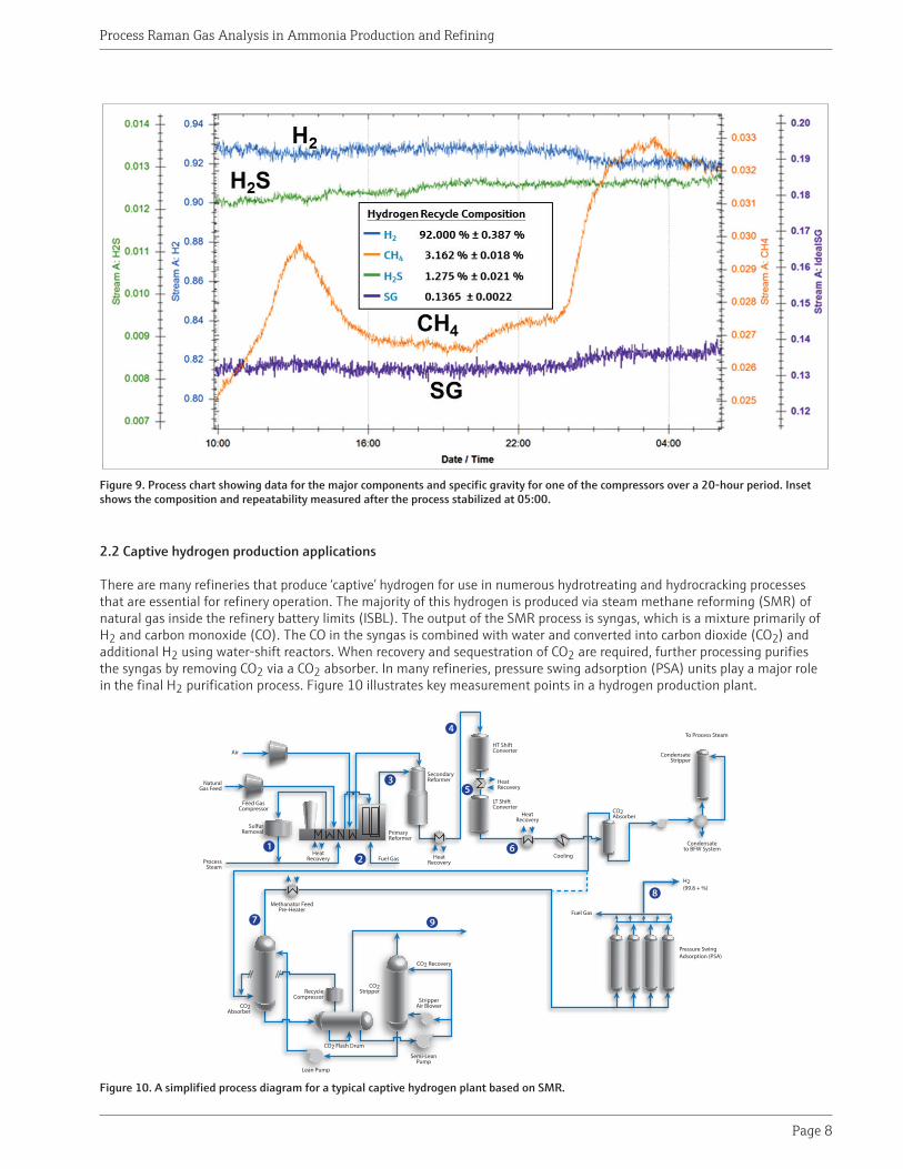
A sample screen shot of the main user interface screen on the Optograf analyzer is shown in Figure 8. This screen provides a high level system view of the most recent analysis on each of the streams, including the pressure, temperature, and composition, as well as the progress of the current data acquisition and the status of the overall analyzer. Figure 9 shows typical process data for the major components of interest to this particular customer over a 20-hour period, including the repeatability achieved for each component and the calculated value for specific gravity. During this particular period, there was fluctuation in the methane content, which stabilized around the 19th hour. The specific gravity value varies concomitantly with this change in methane content, allowing the facility to not only measure the change in specific gravity, but to determine what composition changes are causing it to vary.
Figure 8. Screen shot of the Optograf analyzer main GUI, showing data from a single analysis for the three hydrogen recycle measurement points.
Process Gas In
Bypass Flow
P/T Sensor
Main Flow
Heater
Pneumatic Switch for Automatic Validation
Flow Transmitter to PLC
Raman Probe
PID TemperatureController
Process Raman Gas Analysis in Ammonia Production and Refining
Page 8
Figure 9. Process chart showing data for the major components and specific gravity for one of the compressors over a 20-hour period. Inset shows the composition and repeatability measured after the process stabilized at 05:00.
2.2 Captive hydrogen production applications
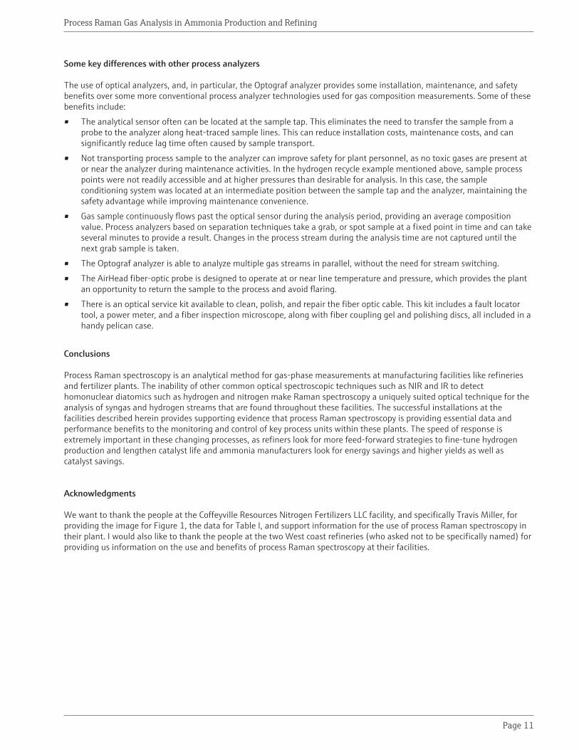
There are many refineries that produce ‘captive’ hydrogen for use in numerous hydrotreating and hydrocracking processes that are essential for refinery operation. The majority of this hydrogen is produced via steam methane reforming (SMR) of natural gas inside the refinery battery limits (ISBL). The output of the SMR process is syngas, which is a mixture primarily of H2 and carbon monoxide (CO). The CO in the syngas is combined with water and converted into carbon dioxide (CO2) and additional H2 using water-shift reactors. When recovery and sequestration of CO2 are required, further processing purifies the syngas by removing CO2 via a CO2 absorber. In many refineries, pressure swing adsorption (PSA) units play a major role in the final H2 purification process. Figure 10 illustrates key measurement points in a hydrogen production plant.
Figure 10. A simplified process diagram for a typical captive hydrogen plant based on SMR.
Air
Natural Gas Feed
HeatRecovery
Feed Gas Compressor
Process Steam
Primary Reformer
Secondary Reformer
Heat Recovery
HeatRecovery
Cooling
Lean Pump
CO2Absorber
CO2 Flash Drum
CO2Stripper
Semi-Lean Pump
Stripper Air Blower
Methanator Feed Pre-Heater
Recycle Compressor
HT Shift Converter
LT Shift Converter
To Process Steam
Condensate to BFW System
Condensate Stripper
Sulfur Removal
Fuel Gas
HeatRecovery
Fuel Gas
CO2 Recovery
H2 (99.8 + %)
Pressure Swing Adsorption (PSA)
CO2Absorber

Process Raman Gas Analysis in Ammonia Production and Refining
Page 9
One U.S. West coast refinery has used a variety of technologies to measure H2 purity at the outlet of the PSA process unit. Initially, the plant used a commercial specific gravity (SG) meter for this measurement. However, due to the non-binary nature and trace contaminants in the stream, the SG meter would often produce spurious results. In addition, the process engineer needed both a good hydrogen measurement and details of the contaminants, which this sensor was unable to provide. The site investigated alternative approaches and settled on one based on solid state sensing technology. This analyzer was installed and was found to be very sensitive to pressure and flow, and ultimately was deemed not sufficiently repeatable for their requirements. The site evaluated process gas chromatography (PGC) and several optical technologies, focusing on process Raman spectroscopy, since other optical technologies that are commercially available, such as near-infrared (NIR) and mid-infrared (NDIR, FTIR) cannot measure hydrogen, whereas the Raman technique can. The site chose to deploy a process Raman system over PGC systems due to the high cost of maintenance and consumables they had experienced with previous PGC installations at the site. In addition, the customer had a preference not to send the effluent from the analyzer to flare. The Raman system analyzes samples at higher pressure than the PGC and other sensor technologies, allowing the facility to find a location downstream to return the sample to the process.
Table III provides details of the process conditions, preferred analysis cycle time, and the expected composition of the outlet of the PSA process unit at this refinery. Figure 11 shows process data for the main stream components in the PSA outlet stream taken over a four day period. A review of the process data from an instrument export shows that over the first three days, the process pressure at the fiber optic probe was dropping steadily, starting at 175 psig and dropping as low as 95 psig. The data shows that, despite this pressure drop, the measurement results remained consistent. At around 14:00 on 07/09/2014, over period of a few minutes, the facility addressed the pressure drop issue, raising the pressure at the sample to around 214 psig. As a consequence of this correction, the hydrogen purity out of the PSA was reduced from three 9’s to two 9’s, more in line with the expected composition indicated in Table III. There was a concomitant increase in both the methane and nitrogen in the sample stream. Figure 12 is a plot of the Raman spectrum both before (a) and after (b) the pressure adjustment. The inset in Figure 12(a) shows the spectral change in N2 and CH4 before (blue) and after (red) the process pressure adjustment.
Table III. Example Stream Composition for PSA Unit Hydrogen Stream
PSA Unit H2 Stream
Temperature (°F) 120
Pressure (psig) 350
Cycle Time (min) 2-4
Hydrogen (%) 99.0
Methane (%) 0.5
Nitrogen (%) 0.4
Carbon dioxide (%) 0.1All composition values are in mol. %

Process Raman Gas Analysis in Ammonia Production and Refining
Page 10
Figure 11. Process data from the outlet of the PSA over a 4-day period, including composition both before and after a a sample pressure issue was addressed.
Figure 12. Representative Raman spectrum taken before (a) and after (b) a pressure issue was detected and addressed, with measured composition. Inset in 12(a) highlights the change in the Raman spectra for the N2 and CH4 minor components before (blue) and after (red) the pressure issue was addressed.
Process Raman Gas Analysis in Ammonia Production and Refining
Page 11
Some key differences with other process analyzers
The use of optical analyzers, and, in particular, the Optograf analyzer provides some installation, maintenance, and safety benefits over some more conventional process analyzer technologies used for gas composition measurements. Some of these benefits include:
• The analytical sensor often can be located at the sample tap. This eliminates the need to transfer the sample from a probe to the analyzer along heat-traced sample lines. This can reduce installation costs, maintenance costs, and can significantly reduce lag time often caused by sample transport.
• Not transporting process sample to the analyzer can improve safety for plant personnel, as no toxic gases are present at or near the analyzer during maintenance activities. In the hydrogen recycle example mentioned above, sample process points were not readily accessible and at higher pressures than desirable for analysis. In this case, the sample conditioning system was located at an intermediate position between the sample tap and the analyzer, maintaining the safety advantage while improving maintenance convenience.
• Gas sample continuously flows past the optical sensor during the analysis period, providing an average composition value. Process analyzers based on separation techniques take a grab, or spot sample at a fixed point in time and can take several minutes to provide a result. Changes in the process stream during the analysis time are not captured until the next grab sample is taken.
• The Optograf analyzer is able to analyze multiple gas streams in parallel, without the need for stream switching.
• The AirHead fiber-optic probe is designed to operate at or near line temperature and pressure, which provides the plant an opportunity to return the sample to the process and avoid flaring.
• There is an optical service kit available to clean, polish, and repair the fiber optic cable. This kit includes a fault locator tool, a power meter, and a fiber inspection microscope, along with fiber coupling gel and polishing discs, all included in a handy pelican case.
Conclusions
Process Raman spectroscopy is an analytical method for gas-phase measurements at manufacturing facilities like refineries and fertilizer plants. The inability of other common optical spectroscopic techniques such as NIR and IR to detect homonuclear diatomics such as hydrogen and nitrogen make Raman spectroscopy a uniquely suited optical technique for the analysis of syngas and hydrogen streams that are found throughout these facilities. The successful installations at the facilities described herein provides supporting evidence that process Raman spectroscopy is providing essential data and performance benefits to the monitoring and control of key process units within these plants. The speed of response is extremely important in these changing processes, as refiners look for more feed-forward strategies to fine-tune hydrogen production and lengthen catalyst life and ammonia manufacturers look for energy savings and higher yields as well as catalyst savings.
Acknowledgments
We want to thank the people at the Coffeyville Resources Nitrogen Fertilizers LLC facility, and specifically Travis Miller, for providing the image for Figure 1, the data for Table I, and support information for the use of process Raman spectroscopy in their plant. I would also like to thank the people at the two West coast refineries (who asked not to be specifically named) for providing us information on the use and benefits of process Raman spectroscopy at their facilities.

Process Raman Gas Analysis in Ammonia Production and Refining
Page 12
References
Van Vuuren, Peter, Sutherland, Scott, Slater, Joe, Esmonde-White, Francis, Faulkner, David, Corie, Philippe, “Optograf™ Analyzer and ‘Pipe centric’ Process and Sampling Interfaces: A New Paradigm for a Total Process Analytical Solution”, ISA AD Symposium, Galveston, TX, April 26-30, 2015.
Chevron Refinery Modernization Project EIR Appendix 3 http://www.chevronmodernization.com/wp-content/uploads/2014/03/Appendix_3_Overview.pdf.
Mak, John Y., Heaven, Dave, Kubek, Dan, Sharp, Curtis, Clark, Mike, 2004, “Synthesis Gas Purification in Gasification to Ammonia/Urea Complex”, Gasification Technologies Council Annual Conference, Washington, DC, October 4-6, 2004.
Black & Veatch, “Fertilizer Plant Demand Driven by Low Natural Gas Prices”, https://www.bv.com/Home/news/solutions/energy/fertilizer-plant-demand-driven-by-low-natural-gas-prices.

Process Raman Gas Analysis in Ammonia Production and Refining
Page 13
Appendix: Raman Spectroscopy Technology Review
Process Raman analyzers are based on inelastic light scattering resulting from directing laser light into a sample. When light interacts with a chemical, it can be absorbed, transmitted, or scattered. Most of scattered light is Rayleigh, or elastic, scattering. A small fraction of scattered photons undergo inelastic, or Raman scattering, losing some energy to vibrational modes of the molecules in the sample. Raman scattered photons have a different wavelength than the incident light. Each type of chemical bond will scatter a different energy, or color, of light, due to the energy states of the chemical bonds between the atoms.
When Raman spectroscopy is used to measure a gas mixture, each of the different component gases scatters a different color of light. If this light is collected and analyzed, the different colors can be used to identify the components of the mixture, and the intensity of each color can be used to quantify each component in the mixture, providing compositional analysis. Figure 13 shows the major components of the Optograf analyzer. Laser light is transmitted via a fiber optic cable (A) to the gas probe (B). Scattered light is transmitted along a collection fiber (C) to the spectrograph (D), where Rayleigh scattered light is removed and the Raman scattered light is diffracted via a holographic transmission grating (E) to spatially separate the different colors. The dispersed light is imaged onto a charge-coupled device (CCD) detector (F). Up to four collection fibers from different process streams can be imaged simultaneously onto the CCD, with compositional results and other pertinent information displayed on the graphical user interface (GUI) of the system (G).
Figure 13. Components of the process Raman Optograf analyzer
Excitation Fiber
Collection Fiber
Gas Probe
Green Laser (532 nm)
Transmission Grating
Spectrograph
Notch Slit
SapphireWindow
Reflector
Focusing OpticsSample
Flow
Pressure
RTD
Embedded Computer/Touchscreen
CCD Detector
Chan 1Chan 2Chan 3Chan 4
Chan 1
Chan 2
Fast Loopat Shelter
EB
FG
C
D
A
Chan 3
Chan 4
Contact4333 W. Sam Houston Pkwy N. Suite 100Houston, TX 77043
Tel +1 713 300 2700 +1 800 619 2861Fax +1 713 856 6623
[email protected]@spectrasensors.comwww.spectrasensors.com
WP Process raman gas analysis in ammonia production and refining (06/17)
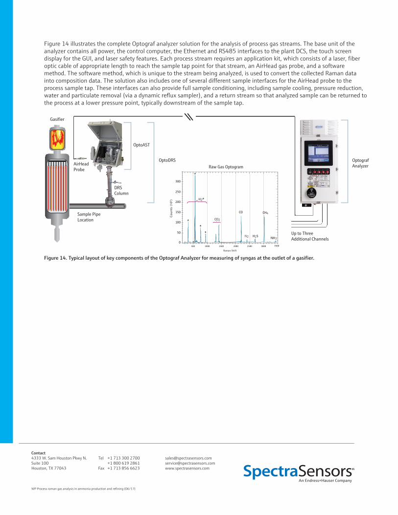
Figure 14 illustrates the complete Optograf analyzer solution for the analysis of process gas streams. The base unit of the analyzer contains all power, the control computer, the Ethernet and RS485 interfaces to the plant DCS, the touch screen display for the GUI, and laser safety features. Each process stream requires an application kit, which consists of a laser, fiber optic cable of appropriate length to reach the sample tap point for that stream, an AirHead gas probe, and a software method. The software method, which is unique to the stream being analyzed, is used to convert the collected Raman data into composition data. The solution also includes one of several different sample interfaces for the AirHead probe to the process sample tap. These interfaces can also provide full sample conditioning, including sample cooling, pressure reduction, water and particulate removal (via a dynamic reflux sampler), and a return stream so that analyzed sample can be returned to the process at a lower pressure point, typically downstream of the sample tap.
Figure 14. Typical layout of key components of the Optograf Analyzer for measuring of syngas at the outlet of a gasifier.
AirHeadProbe
OptoAST
OptografAnalyzer
Up to Three Additional Channels
DRS Column
Sample Pipe Location
Gasifier
OptoDRSRaw Gas Optogram
300
100
50
0
150
200
250
500 1000 1500 2000 3000 35002500
Raman Shift
H2
NH3H2SN2
CH4
CO2
CO