white paper october 2006 rrc06 procedures with … software solutions in radiocommunications white...
TRANSCRIPT

1/14
Software solutions in radiocommunications
White Paper October 2006 RRC06 procedures with ICS manager and ICS telecom (Appendix 4 of the final acts) Thomas Garand

2/14
Introduction ICS manager and ICS telecom integrate planning process for Terrestrial digital radiocommunication services (T-DAB and DVB-T) according to specifications approved in Geneva during RRC06 meeting.
More particularly, ATDI’s tools make it possible to follow the procedures defined in the Section I and the Section II of the Appendix 4 of the final acts.
• The Section I define the limits and methodology for determining when agreement with another administration is required when an administration proposes to modify the Plan or to coordinate an assignment to a station in another primary terrestrial service.
• The Section II describes the method to be used for the examination of conformity of
the conversion of a digital Plan entry comprising an allotment or an allotment with linked assignments to one or more assignments.
ATDI’s tools allows thus:
• To identify potentially affected administrations (Section I), and;
• To carry out the examination of conformity with the digital Plan entry (Section II). Here is a quick description of how these processes are integrated in ATDI’s tools.

3/14
Identification of the potentially affected administrations The procedure of identification is automatically performed by ICS Manager and is activated as soon as the user confirms that the modifications that he wants to bring to the record require an identification of administrations potentially affected.
As soon as the procedure is accepted, the five following stages are carried out automatically in ICS Manager:
• Step 1 – Establishment of the 1 000 km contour In this step, ICS Manager creates a 1 000 km contour that the user can display.
• Step 2 – Selection of administrations whose broadcasting service is potentially affected In this step, ICS Manager generates a coordination contour by calculating with a one degree step in azimuth around the coordinating broadcasting station the distance at which the trigger field strength is reached.
This calculation is based on:
The propagation model described in Chapter 2 of Annex 2 to the Final
Acts;

4/14
A Digital Terrain model ; A receiving antenna height of 10 m ;
A trigger coordination value corresponding to the broadcasting service
to be protected specified in Table AP1.1 of the Appendix 1 to Section 1;
A reference point according the coordination scenario;
The characteristics of the signal sources that are notified in the Plan.
The user can display the coordination contour that has been created:

5/14
• Step 3 – Selection of assignments of other services located in the 1 000 km contour In this step ICS Manager makes it possible to select assignments of other services that could be affected by the changes. To carry out this selection the BRIFIC database containing other primary terrestrial services must be imported in ICS Manager.
Based on this database ICS Manager reads the coordinates of every station and checks if they are located within the 1000 km contour.
Finally ICS Manager generates a file containing the name of the assignments which are located within the 1 000 km contour, as well as, their service, their administration and the trigger coordination value, and the receiving antenna height associated to the service.
System to be
protected System
type code Frequency
range Name Administration X Y Trigger field
strength (dBµV/m) Height of Rx antenna (m)
Analog private mobile radio NV Bande III FLOBECQ BEL 3.41
55 50.4548 30 20
Analog private mobile radio NV Bande III MALMEDY BEL 5.59
15 50.2436 30 20
Analog private mobile radio NV Bande III
EIFEL BAERBELKRE
UZ D 6.27
36 50.2525 30 20
Analog private mobile radio NV Bande III KREHBERG D 8.43
54 49.4105 30 20
Analog private mobile radio NV Bande III LANCASTER G
-2.46523
54.052 30 20
All listed assignments can be displayed on a map.

6/14
• Step 4 – Construction of coordination contours In this step ICS Manager creates a coordination contour for every service listed at step 3. The contours are created by using exactly the same method as step 2 and according to the trigger coordination values and the heights of the receiving antenna, specific to each service.
• Step 5 – Identification of potentially affected administrations In this step ICS Manager automatically generates the list of the administrations with which it is necessary to coordinate:

7/14
I.e. those:
where the boundaries are crossed or enclosed by the coordination contour created at step 2, and ;
the locations of receiving stations/service areas of other primary
services identified in Step 3 are crossed or enclosed by the coordination contours created during step 4.

8/14
In this example, the identified administration with which coordination is required for other primary services is Belgium (BEL).

9/14
Examination of conformity The procedure of examination of conformity is carried out at the same time by ICS Manager and ICS Telecom. This procedure is carried out in 8 steps, which are as follows :
• Step 1 – Verification of the channel used by the digital Plan entry implementation;
• Step 2 – Verification of the geographical location of the digital Plan entry
implementation;
• Step 3 – Construction of the “broadcasting” coordination contour; • Step 4 – Identification of other primary services; • Step 5 – Construction of the new coordination contour;
• Step 6 – Construction of the geometrical contours and of the calculation
points;
• Step 7 – Construction of the Cut-off field-strength contour, and;
• Step 8 – Final comparison of the total interfering field strengths. The following figure summarizes the structure of this process.

10/14
Step 1: Channel verification
Accepted
Rejected
End of the Process : Examination
rejected
Step 2: Localization verification
Rejected
Accepted
Step 3: Creation of the cut-off field-strength contour
Contour exceeds the limits of the territory
Contour doesn’t extend beyond the national boundary
Step 4: Identification of other primary
terristrial services
Other services identified
Step 5: Construction of a new cut-off field-
strength contour
Contour exceeds the limits of the territory
Step 6: Creation of geometrical contours and calculation points
No other services
End of the Process: Examination conformed
Contour doesn’t extend beyond the national boundary
Step 7: Creation of the interference
envelope
Step 8: Interference calculation of the implementation at every calculation
points
Interference of implementation <= Interference envelopeat every calculation points
End of the Process: Examination conformed
Interference of implementation > Interference envelopeat one or several calculation points
End of the Process : Examination
rejected
ICS TELECOM
ICS MANAGER

11/14
The steps 1 to 7 can be managed by ICS Manager and make it possible to identify the relevant calculation points and create the interference envelope derived from the characteristics of the digital Plan entry. The 5 different following types of digital Plan entry are taken into account in this process:
1. Digital Plan entry is an allotment;
2. Digital Plan entry is an assignment;
3. Digital Plan entry is an allotment with linked assignments;
4. Digital Plan entry is a set of assignments with a common SFN;
5. Digital Plan entry is an assignment linked to an allotment with no SFN
identifier. At the end of step 7, a csv file is automatically generated as well as a “read me” file, giving the following information:
• Calculation_points_F_73029-33.txt: date of creation, notifying administration,
administration unique reference ID, propagation model, version of the propagation model, % of Time, % of Location, clearance angle taken into account or not, Mobile antenna height taken into account or not, type of receiver environment.
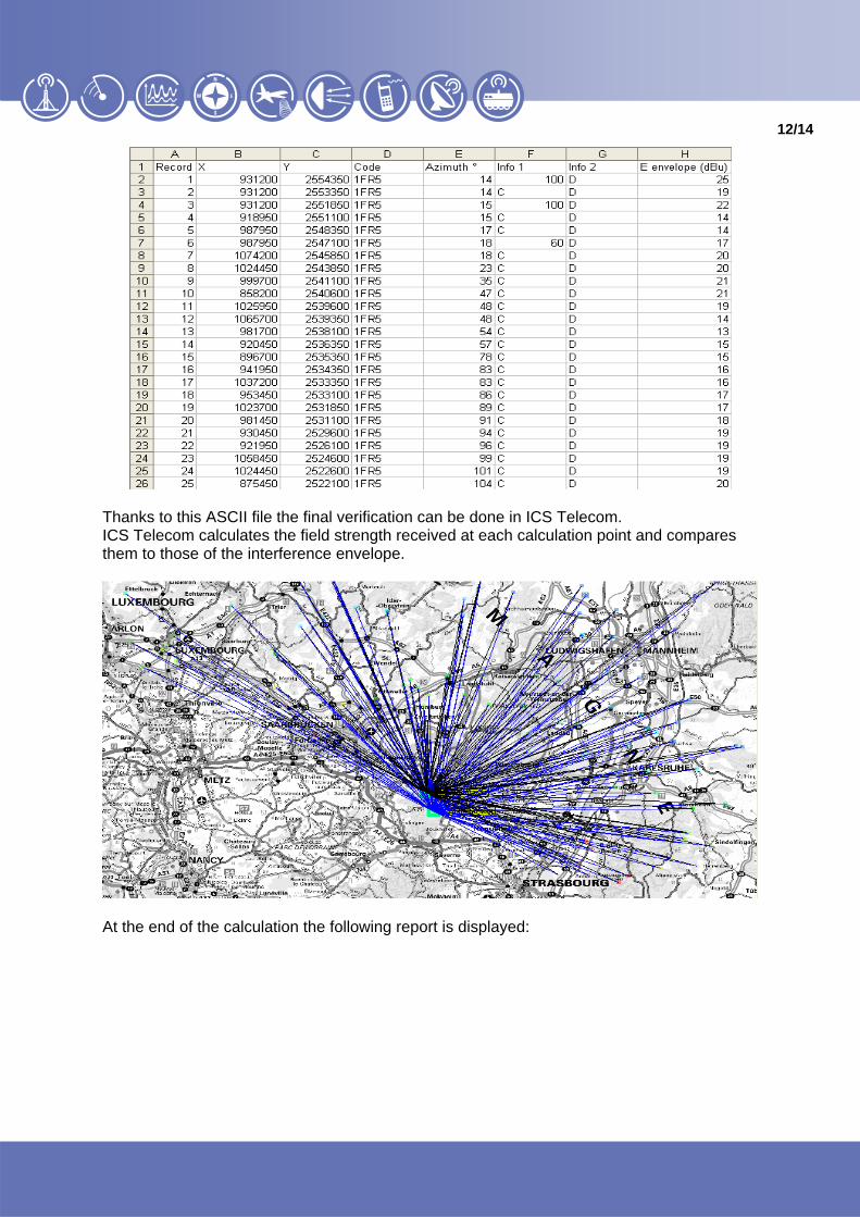
• Calculation_points_F_73029-33.csv: calculation point number, X, Y, coordinate code, azimuth, Info 1: location of the calculation point (on the geometrical contour at 60 km: 60, on the geometrical contour at 100 km: 100… on the cut-off field strength contour: C), Info 2: administration on which the calculation is located and the interference field strength (E envelope).
12/14
Thanks to this ASCII file the final verification can be done in ICS Telecom. ICS Telecom calculates the field strength received at each calculation point and compares them to those of the interference envelope.
At the end of the calculation the following report is displayed:

13/14
If at one calculation point the interference field-strength coming from the converted assignment(s) is greater than the interference envelope then the examination of conformity is rejected (NOK).
User can display a table (csv file) which summarizes the calculations made and the difference found on each calculation point.

14/14
To create the modified notification files, follow the process define in section 7.1.
ATDI Inc.2, Pidgeon Hill Drive, Suite 560 Sterling - VA 20165 - USA Tel. +1 703 848 4750 Fax +1 703 848 4752 e-mail : [email protected] http://www.atdi-us.com
ATDI SA 8, rue de l’Arcade 75008 Paris - France Tel. +33 (0) 53 30 89 40 Fax +33 (0)1 53 30 89 49 e-mail : [email protected] http://www.atdi.com
ATDI Ibérica c/Manuel González Longoria,8 28010 Madrid - Spain Tel. +34 91 44 67 252 Fax +34 91 44 50 383 e-mail : [email protected] http://www.atdi.es
ATDI Ltd. Kingsland Court - Three Bridges Road Crawley - West Sussex - RH10 1HL - UK Tel. +44 (0)1293 522052 Fax +44 (0)1293 522521 e-mail : [email protected] http://www.atdi.co.uk
ATDI SAL812 Tabaris, Avenue Charles Malek Achrafieh, Beirut - Lebanon Tel. +961 1 330 331 Fax +961 1 216 206 e-mail : [email protected] http://www.atdi.com
ATDI EST Bd. Aviatorilor, 59 Bucharest Romania Tel +40 21 222 42 10 Fax +40 21 222 42 13 e-mail : [email protected] http://www.atdi.ro
ATDI OOO Sadovnicheskaya st. 72 bld 1 115035 Moscow - Russian Federation Tel. +7 095 252 96 10 Fax +7 501 408 50 74 e-mail : [email protected] http://www.atdi.ru
ATDI South Pacific PTY Ltd79 Macarthur Street - Ultimo NSW 2007 - Australia Tel. +61 (0)2 9213 2200 Fax +61 (0)2 9213 2299 e-mail : [email protected] http://www.atdi.com
ATDI UA partnership with LISerbitskogo str. 1 02068 Kiev Ukraine Tel +380 44 564 33 68 e-mail : v [email protected] http:// www.lissoft.com.ua
Software solutions in radiocommunications