wheelchair drive : dan · pdf fileinteresting heavy-duty attendant wheelchair drive unit in...
TRANSCRIPT
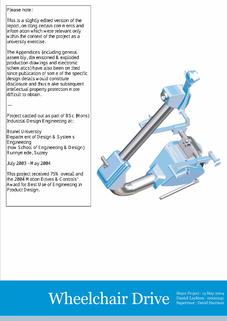
Major Project · 14 May 2004
Daniel Lockton · 0000241Supervisor : David HarrisonWheelchair Drive

Wheelchair Drive Specification
-Electric hub motor drive to fit common wheelchair types and sizes
-Variable speed drive up to 4 mph (legal maximum)
- Speed set by the user (cruise control style)
-Allows wheelchair to climb & descend ramps, lowered kerbs &
reasonable gradients safely
-Allows wheelchair to manœuvre easily without twisting user’s spine
-Controllable easily and safely by wheelchair user or an attendant
-Controllable using one hand only, even by attendant
-Controllable by attendant walking alongside chair, alleviating
feeling of isolation
-Can be used occasionally or continuously to suit the user
-Easy to remove and reattach
-Can be transferred between different chairs, adjusts to width
-Quiet, smooth operation which will not draw unfavourable attention
-All to be achieved at a lower cost than a powerchair
-Electric hub motor drive to fit common wheelchair types and sizes
-Variable speed drive up to 4 mph (legal maximum)
- Speed set by the user (cruise control style)
-Allows wheelchair to climb & descend ramps, lowered kerbs &
reasonable gradients safely
-Allows wheelchair to manœuvre easily without twisting user’s spine
-Controllable easily and safely by wheelchair user or an attendant
-Controllable using one hand only, even by attendant
-Controllable by attendant walking alongside chair, alleviating
feeling of isolation
-Can be used occasionally or continuously to suit the user
-Easy to remove and reattach
-Can be transferred between different chairs, adjusts to width
-Quiet, smooth operation which will not draw unfavourable attention
-All to be achieved at a lower cost than a powerchair:
Development through prototypes - different types of motor,
different drive, steering and control configurations
Dan Lockton 0000241Dan Lockton 0000241

1
Abstract
The project comprises the development of an electric power unit to be retro-
fitted to manual wheelchairs, providing the wheelchair user or an attendant
with drive, steering and regenerative braking at a much lower cost (and with
much greater flexibility in use) than a standard powerchair. Through
investigation of a wide variety of possible configurations, a final specification
is reached involving a compact geared hub motor mounted to the front of the
chair, with an innovative steering and control system based on maximising the
manoeuvrability of the chair. The main mechanical performance criterion is
that a 40 lb Remploy 8L-style chair fitted with the unit be able to carry a 15
stone load up a 1 in 7 slope at a constant 2 mph. Extensive research is
presented into comparable existing mobility products, making use of the
author’s work experience in the field, and the needs and expectations of
potential users.

2
Contents
Introduction
Background
(1) Product specification
(1.1) Review of existing products and configurations
(1.2) Control
(1.3) Drive
(1.4) Position
(1.5) Steering
(1.6) Wheelchair designs
(1.7) Wheelchair users and capabilities
(1.8) Specification
(2) Investigative development: to January 2004
(2.1) Twin-wheeled drive, rear-mounted, with differential steering
(2.2) Single-wheeled drive, rear-mounted, with steering ahead of the wheel
(2.3) Single-wheeled drive, rear-mounted, with steering above the wheel
(2.4) Single-wheeled drive, rear-mounted, with nutation steering
(2.5) Single-wheeled drive, front-mounted, with handlebar/articulated steering
(2.6) Motors
(2.7) Mechanics
(2.8) Control technology
(2.9) Usability
(2.10) User consultation
(2.11) Legal requirements and standards
(3) Development of design : to May 2004
(3.1) Manual propulsion mode
(3.2) Development of subframes and fitting assembly
(3.3) User interface
(3.4) Battery choice
(3.5) Controller casing
(3.6) Steering column
(3.7) User consultation
Evaluation
References

3
Acknowledgements
I would like to thank all those who have helped with the development of this project,
including:
Michael O’Donnell for his fabrication and design skills
Geoffrey Gane, C.F. Hewerdine Ltd, for his advice and support
David Constantine, Motivation, for his suggestions and comments
Richard Torrens, 4QD, for rapid MOSFET replacement
Richard Thomas & Phil Wilmore, Brunel, for helping with testing the brushless controller
Len Breen for giving us somewhere to work
Dr David Harrison for providing support as a supervisor
Paul Turnock for his advice early on in the project
All the workshop staff at Brunel for their help and tolerance
My brother, Tom Lockton, for encouragement and prototype testing
4
Introduction
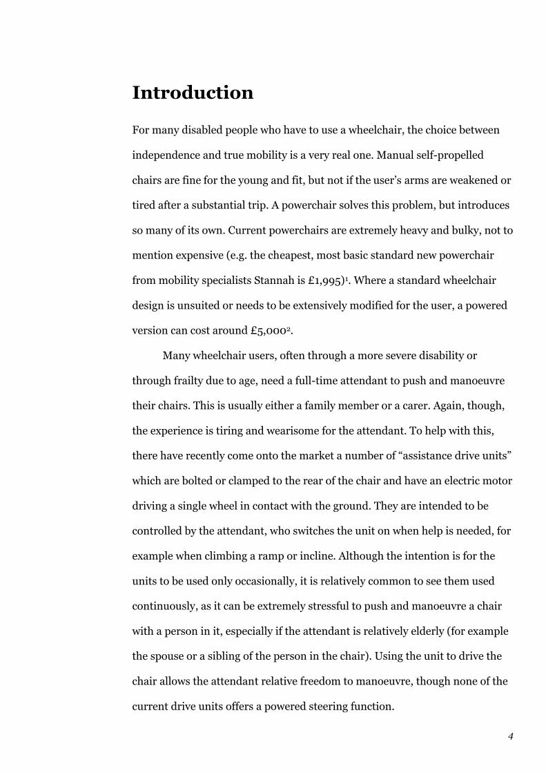
For many disabled people who have to use a wheelchair, the choice between
independence and true mobility is a very real one. Manual self-propelled
chairs are fine for the young and fit, but not if the user’s arms are weakened or
tired after a substantial trip. A powerchair solves this problem, but introduces
so many of its own. Current powerchairs are extremely heavy and bulky, not to
mention expensive (e.g. the cheapest, most basic standard new powerchair
from mobility specialists Stannah is £1,995)1. Where a standard wheelchair
design is unsuited or needs to be extensively modified for the user, a powered
version can cost around £5,0002.
Many wheelchair users, often through a more severe disability or
through frailty due to age, need a full-time attendant to push and manoeuvre
their chairs. This is usually either a family member or a carer. Again, though,
the experience is tiring and wearisome for the attendant. To help with this,
there have recently come onto the market a number of “assistance drive units”
which are bolted or clamped to the rear of the chair and have an electric motor
driving a single wheel in contact with the ground. They are intended to be
controlled by the attendant, who switches the unit on when help is needed, for
example when climbing a ramp or incline. Although the intention is for the
units to be used only occasionally, it is relatively common to see them used
continuously, as it can be extremely stressful to push and manoeuvre a chair
with a person in it, especially if the attendant is relatively elderly (for example
the spouse or a sibling of the person in the chair). Using the unit to drive the
chair allows the attendant relative freedom to manoeuvre, though none of the
current drive units offers a powered steering function.
5
What is apparent is that there is very little currently available that gives
the user of a self-propelled wheelchair assistance when required (even
continuously). It is very difficult to use one of the add-on assistance drive
units in this way since they are designed to be controlled by an attendant, who
can steer the chair by using the handlebars on the rear. Control of the unit by
the chair user is strongly warned against by all of the attendant drive unit
manufacturers3.
The following table examines the strengths and weaknesses of five
different wheelchair propulsion options; as can be seen, the final option offers
a notable combination of advantages.

6
Strengths Weaknesses Conclusions
Manual chair(self-propelled)usually large back wheels
-Allows the user to exercise-Allows the user full control of manœuvring-Lightweight-Independence
-Very much dependent on fitness of user-Can be limiting if user tires easily
-Most suitable for ‘active’ users, usually younger, with leg disabilities/injuriesrather than spinal-In practice this is the case in the UK
Manual chair(attendant-propelled/transit)usually small back wheels
-Allows the user to rest-Control by someone who is fitter/perhapsquicker reflexes-Lightweight
-Makes user dependent on at attendant or carer-Can be tiring for carer (especially if elderly)-Gives user no exercise-Removesindependence
-More suitable for elderly users or those who require a carer orattendant anyway-Elderly carers are often almost as frail as the chair user, thus limiting
Standardpowerchair
-Eliminatesproblems of user tiredness-Extends range of userindependence
-Gives user no exercise-Too heavy (due to batteries) to be self-propelled in an emergency-High initial cost
-Most suitable for more severely disabled users-A long-term solution
Detachabledrive/assistanceunit(attendant-controlled)
-Eliminatesproblems of user tiredness- Control by someone who is fitter/perhapsquicker reflexes
-Makes user dependent on attendant or carer-Gives user no exercise
-A neat, limited solution particularly for elderly couples, but offers no independence
Detachabledrive/assistanceunit(user-controlled)
-Allows the user full control of manœuvring-Allows user to exercise when desired-Lessensproblems of user tiredness-Extends range of userindependence
-User has to carry around the weight of batteries attached to chair
-Combines the advantages of power assistance with the exercise and freedombenefits of the self-propelled manual chair: gives choice, and independence

7
Background
On my work placement as part of my degree, I worked as a product designer
and industrial design engineer for the UK arm of Daka Development, a
Hongkong-based design and manufacturing company which is also a
shareholder in Sinclair Research Limited. One of the Daka/Sinclair products
with which I was involved was a wheelchair assistance unit (the ZA20
Wheelchair Drive Unit) developed and sold in conjunction with Sir Clive; this
was designed as a lightweight, simple, low-priced unit to help the attendant
occasionally when assistance was needed (but not intended for continuous use
— and certainly not safe for the wheelchair user to control on his or her own).
In talking to wheelchair users, buyers of the ZA20, potential buyers and
distributors of this product, and visiting shows and mobility centres where a
wide range of different wheelchairs, scooters and assistance products were on
show and available to test, I came increasingly to the conclusion that there
was potential for a different kind of device to any currently in production,
which could make a big difference to the lives of many wheelchair users (and
their families).
As the ideas became clearer in my mind, I examined carefully the other
assistance units and powerchairs on the market, and also did extensive patent
searches to see what other ideas had been developed but not put into
production. For example, the Trevor Baylis Foundation has designed an
interesting heavy-duty attendant wheelchair drive unit in the shape of a
barrel, called the Troll, which is not yet in production. I discussed the design
with Mr Baylis (and later the actual designer – see section 2.11) at length and
tried the prototype. At an international mobility and rehabilitation show in

8
Düsseldorf (where I was providing technical support on the Daka Europe
stand), I was able to test and compare products from the German company
Alber, arguably the leader in this field, and discuss the technology with
engineers from the company. The Alber range contains some outstanding
designs4, and they are manufactured to extremely high standards, but they are
priced (£2,500+ for just the assistance device5) for the German market where
private health insurance pays for the majority of mobility products.
Daka/Sinclair did not intend to pursue any other types of drive unit as
there were many other unrelated products with a greater priority, but I was
interested in developing the idea much further and so decided to do it as my
own project, starting with some preliminary investigations in summer 2003
(and an unfortunately unsuccessful approach to the Audi Design Foundation
for some support6), and continuing when I returned to Brunel, Runnymede, in
October. The remainder of this report details the progress I have made up to
the submission date for the project (14 May 2004).
Daniel Lockton – www.danlockton.co.uk
148 College Hall
Runnymede
14 May 2004
9
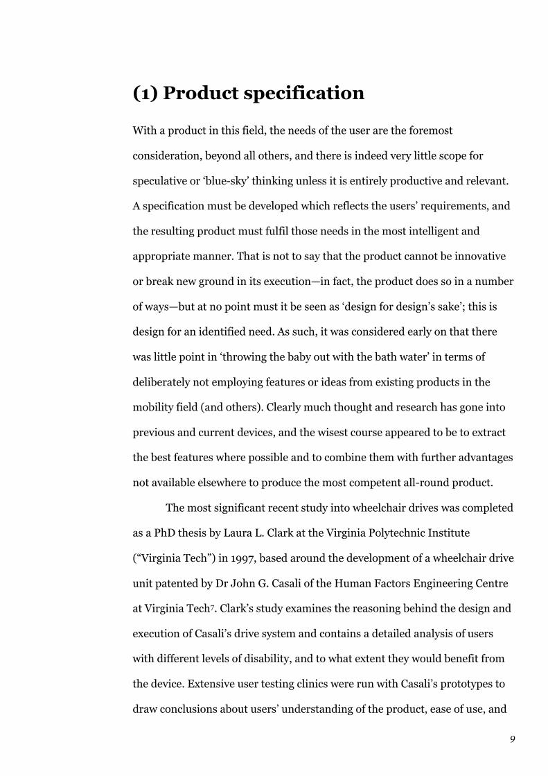
(1) Product specification
With a product in this field, the needs of the user are the foremost
consideration, beyond all others, and there is indeed very little scope for
speculative or ‘blue-sky’ thinking unless it is entirely productive and relevant.
A specification must be developed which reflects the users’ requirements, and
the resulting product must fulfil those needs in the most intelligent and
appropriate manner. That is not to say that the product cannot be innovative
or break new ground in its execution—in fact, the product does so in a number
of ways—but at no point must it be seen as ‘design for design’s sake’; this is
design for an identified need. As such, it was considered early on that there
was little point in ‘throwing the baby out with the bath water’ in terms of
deliberately not employing features or ideas from existing products in the
mobility field (and others). Clearly much thought and research has gone into
previous and current devices, and the wisest course appeared to be to extract
the best features where possible and to combine them with further advantages
not available elsewhere to produce the most competent all-round product.
The most significant recent study into wheelchair drives was completed
as a PhD thesis by Laura L. Clark at the Virginia Polytechnic Institute
(“Virginia Tech”) in 1997, based around the development of a wheelchair drive
unit patented by Dr John G. Casali of the Human Factors Engineering Centre
at Virginia Tech7. Clark’s study examines the reasoning behind the design and
execution of Casali’s drive system and contains a detailed analysis of users
with different levels of disability, and to what extent they would benefit from
the device. Extensive user testing clinics were run with Casali’s prototypes to
draw conclusions about users’ understanding of the product, ease of use, and
10
control issues, though the report does not contain information on how the
prototype might have been improved in response to users’ comments. Clark
looks briefly at a few other designs of wheelchair drive in the U.S., most of
which had ceased production by the time the report was compiled8. Overall,
Clark’s report is a useful summary of many of the issues involved in designing
in this field, but since it presents Casali’s wheelchair drive design as
something of a fait accompli, it is not necessarily a design study in the same
manner as this report is intended to be.
(1.1) Review of existing products and
configurations
The range of existing products in the field of wheelchair drives, assistance
devices and power attachments was investigated. The scope of this research
included products currently on the market (in the UK, Europe and US) and
some patents for devices which appear never to have been produced, but are
interesting nonetheless from a design and engineering point of view. Obsolete
products were also included where sufficient details could be acquired.
The matrix of products is included on the following fold-out pages9;
some product brochures and catalogues are included in the appendix10.
It is clear, from looking at the products in the matrix, that there are a
number of design configurations which have been tried in the past, relating to
control, drive, position and steering, and each of these configurations
will be discussed below.

© Dan Lockton, Brunel University Department of Design & Systems Engineering, Runnymede, Surrey, October 2003 ————1
Model Control Drive Position Steering Power / W (hp)
Max speed / mph Price Notes
SinclairZA20 WDU
Attendant Fifth wheel Rear, centre X 220 (0.3) 4 £3051 Intended as assistance on ramps and slopes for attendant. Very lightweight & compact
TGA Power Pack
Attendant Fifth wheel Rear, centre X 200 (0.27) 4 £6152 Heavy-dutyversion also available
AlberViamobil
Attendant Fifth wheel Rear, centre X 4 £1,5003
© Dan Lockton, Brunel University Department of Design & Systems Engineering, Runnymede, Surrey, October 2003 ————2
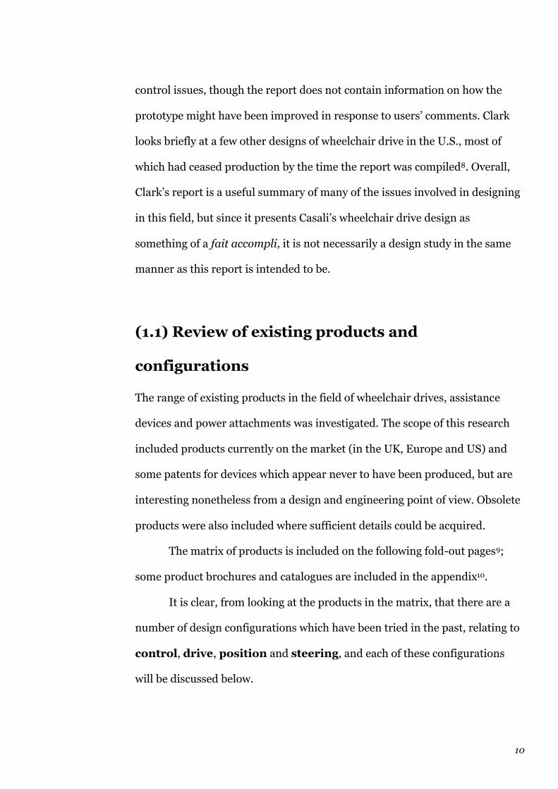
Alber e-Motion
User Replacement wheels
Replacingrear wheels
Differential,manuallyactivated
4 £2,9954 Clever sensors in rims match the power applied by the user to allow exercise while assisting drive. Batteries inside hubs with motors
Alber e-Fix User Replacement wheels
Replacingrear wheels
Differential,electronic
4 £2,9955 Batteries insidehubs with motors
SunrisePowertecF16 / QuickieExtender
Dual Replacement wheels
Replacingrear wheels
Differential,electronic
4 £2,2736 Fits only certain Sunrise chairs
© Dan Lockton, Brunel University Department of Design & Systems Engineering, Runnymede, Surrey, October 2003 ————3
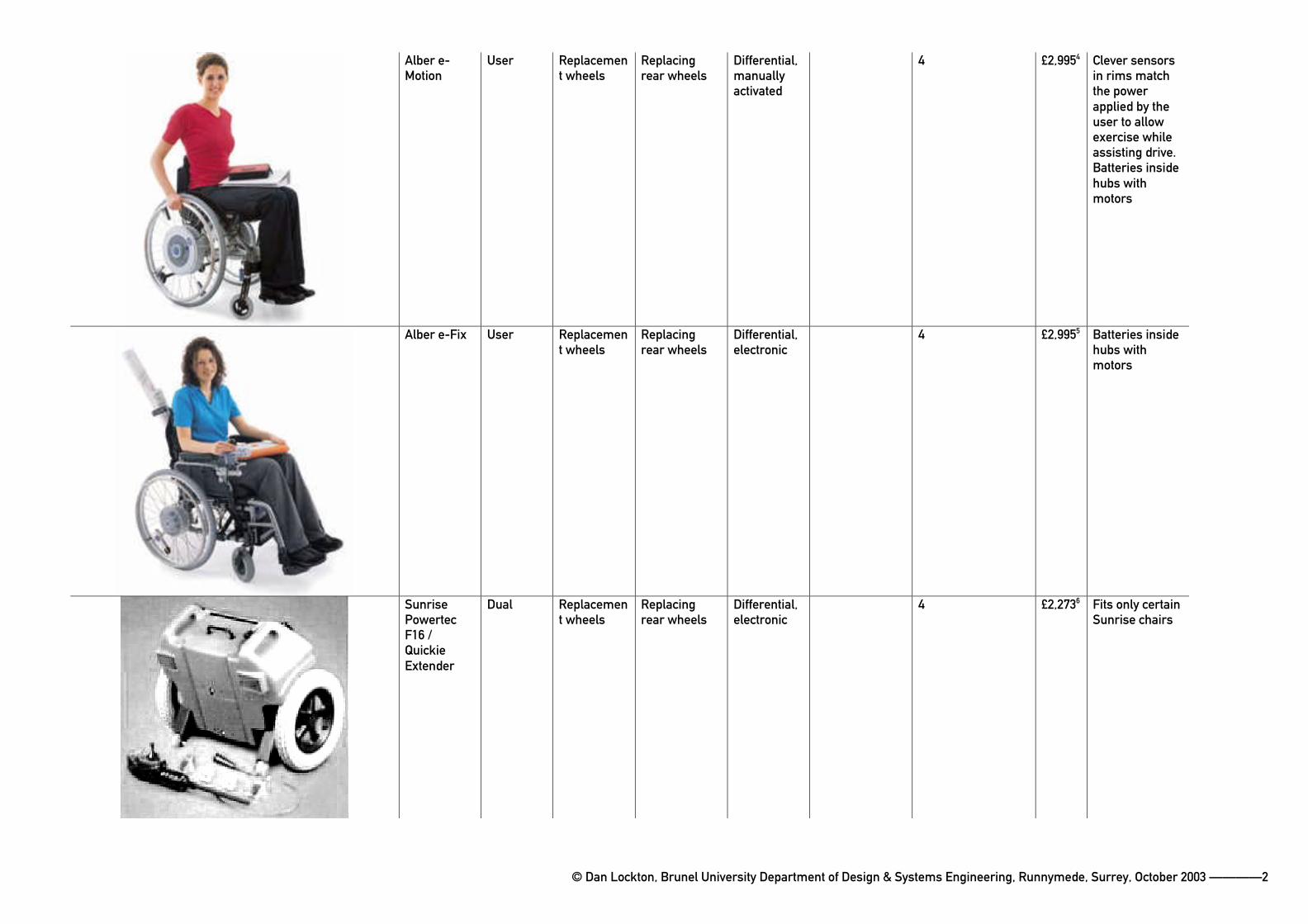
PDQPowerTrike
User Fifth wheel Front, as add-on handlebars & forks
Drive wheel turnsmanually -handlebars
150 (0.2) 11 £2,0007 Often used as a road vehicle, coming under electricallyassisted bicycle regulations in UK
No picture available CowalPower Kit
Dual Rollers on tyres
Ahead of rear wheels
Differential,electronic
600 (0.8) 4 £1,5008
TzoraSamson‘PD1’
Attendant Fifth wheel Rear, centre X 175 (0.25) 4
TzoraSamsonPD2 / Nabco Assist
Attendant Fifth & sixth wheels
Rear, centre X 4
© Dan Lockton, Brunel University Department of Design & Systems Engineering, Runnymede, Surrey, October 2003 ————4
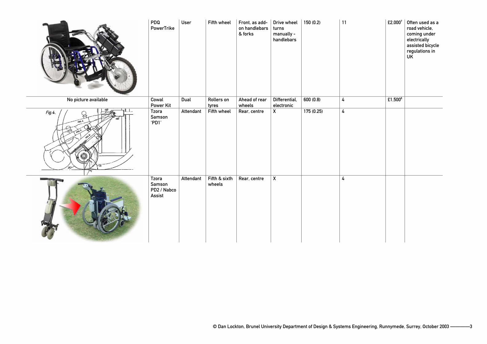
TzoraSamsonPD3
User Replacement wheels
Replacingrear wheels
Differential,electronic
4
TzoraSamsonPD4
Attendant Fifth wheel Rear, centre X 4
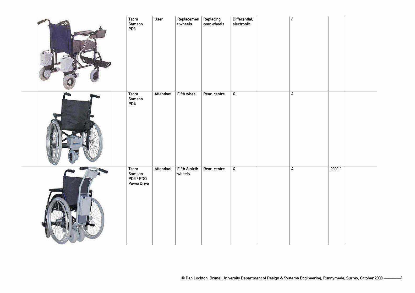
TzoraSamsonPD6 / PDQ PowerDrive
Attendant Fifth & sixth wheels
Rear, centre X 4 £90013
© Dan Lockton, Brunel University Department of Design & Systems Engineering, Runnymede, Surrey, October 2003 ————5
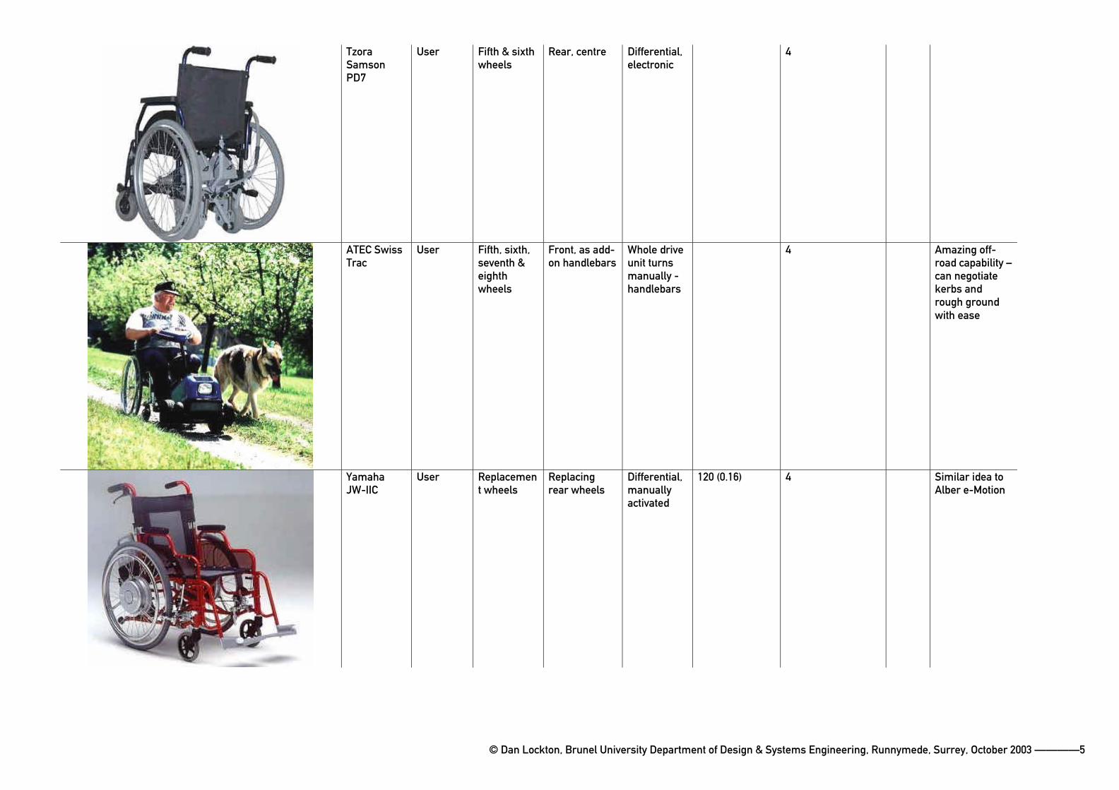
TzoraSamsonPD7
User Fifth & sixth wheels
Rear, centre Differential,electronic
4
ATEC Swiss Trac
User Fifth, sixth, seventh & eighthwheels
Front, as add-on handlebars
Whole driveunit turns manually -handlebars
4 Amazing off-road capability –can negotiate kerbs and rough ground with ease
YamahaJW-IIC
User Replacement wheels
Replacingrear wheels
Differential,manuallyactivated
120 (0.16) 4 Similar idea to Alber e-Motion
© Dan Lockton, Brunel University Department of Design & Systems Engineering, Runnymede, Surrey, October 2003 ————6
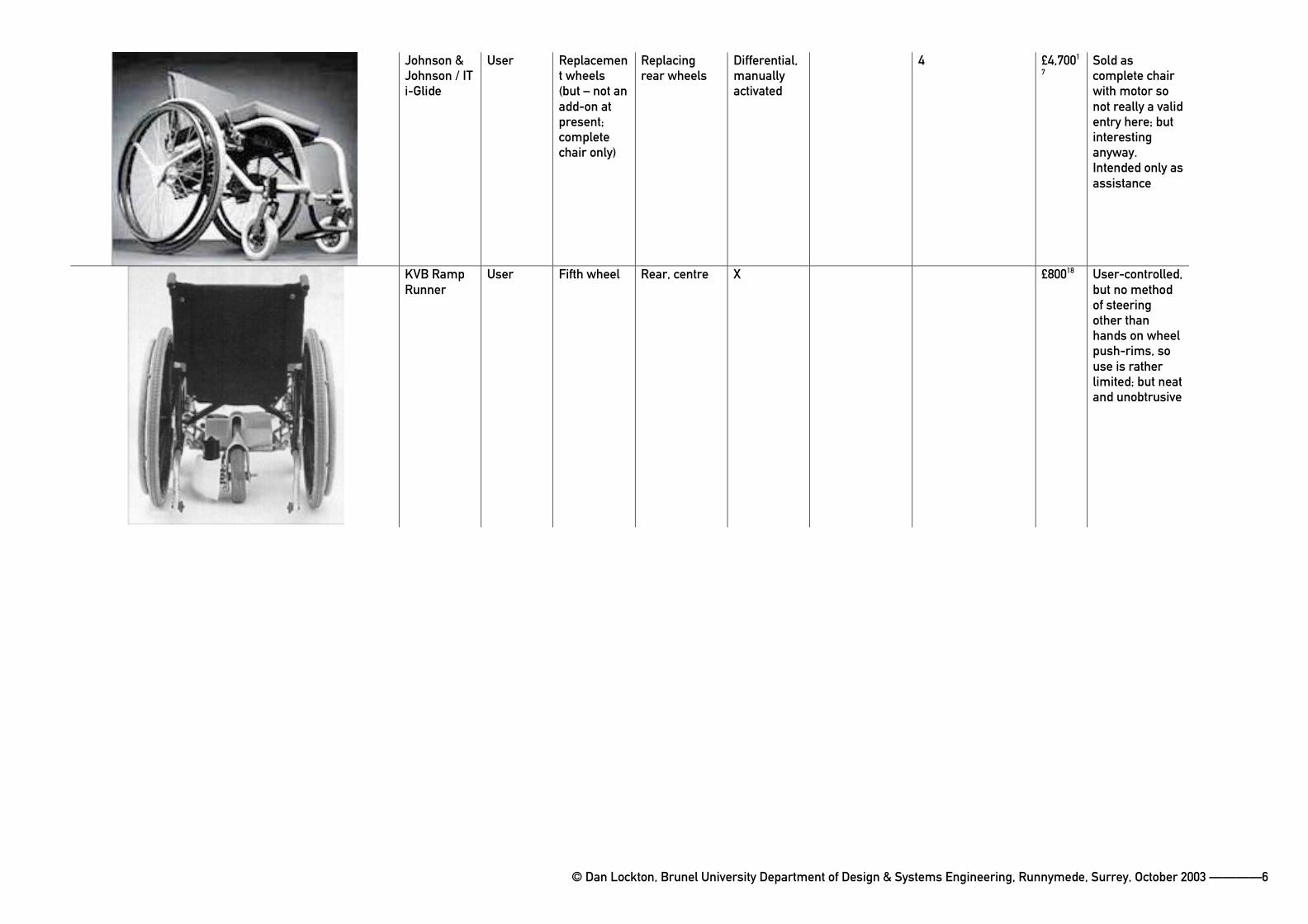
Johnson & Johnson / IT i-Glide
User Replacement wheels (but – not an add-on at present;completechair only)
Replacingrear wheels
Differential,manuallyactivated
4 £4,7001
7Sold as complete chair with motor so not really a valid entry here; but interestinganyway.Intended only as assistance
KVB Ramp Runner
User Fifth wheel Rear, centre X £80018 User-controlled,but no method of steeringother than hands on wheel push-rims, so use is rather limited; but neat and unobtrusive
© Dan Lockton, Brunel University Department of Design & Systems Engineering, Runnymede, Surrey, October 2003 ————7
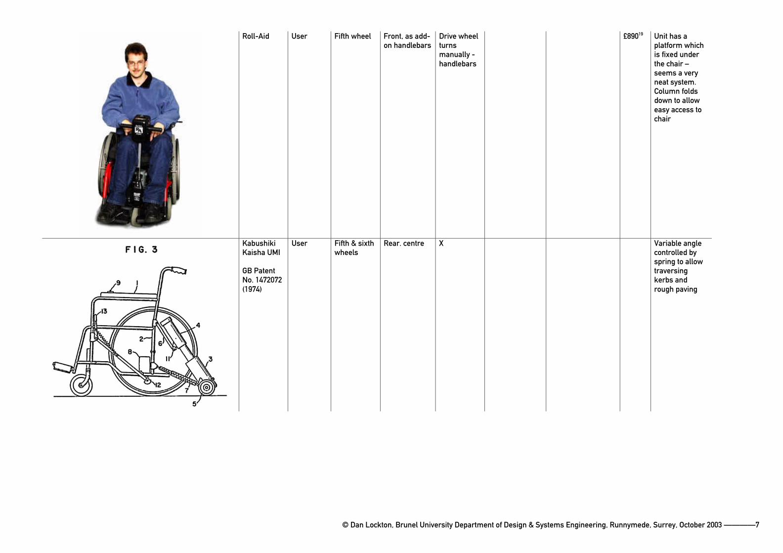
Roll-Aid User Fifth wheel Front, as add-on handlebars
Drive wheel turnsmanually -handlebars
£89019 Unit has a platform which is fixed under the chair –seems a very neat system. Column folds down to allow easy access to chair
KabushikiKaisha UMI
GB Patent No. 1472072 (1974)
User Fifth & sixth wheels
Rear. centre X Variable angle controlled by spring to allow traversingkerbs and rough paving
© Dan Lockton, Brunel University Department of Design & Systems Engineering, Runnymede, Surrey, October 2003 ————8
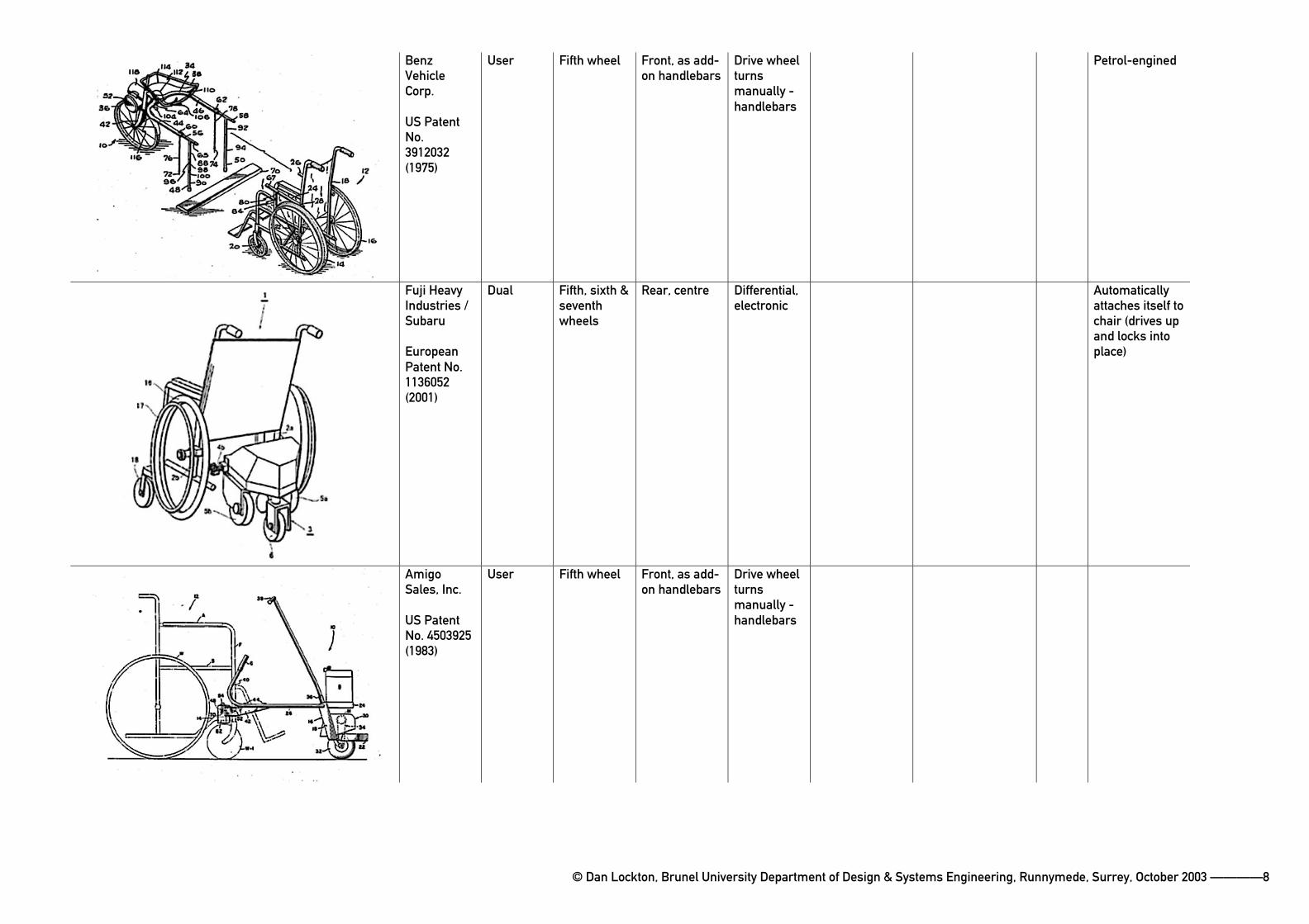
BenzVehicleCorp.
US Patent No.3912032(1975)
User Fifth wheel Front, as add-on handlebars
Drive wheel turnsmanually -handlebars
Petrol-engined
Fuji Heavy Industries / Subaru
EuropeanPatent No. 1136052(2001)
Dual Fifth, sixth & seventhwheels
Rear, centre Differential,electronic
Automaticallyattaches itself to chair (drives up and locks into place)
AmigoSales, Inc.
US Patent No. 4503925 (1983)
User Fifth wheel Front, as add-on handlebars
Drive wheel turnsmanually -handlebars
© Dan Lockton, Brunel University Department of Design & Systems Engineering, Runnymede, Surrey, October 2003 ————9
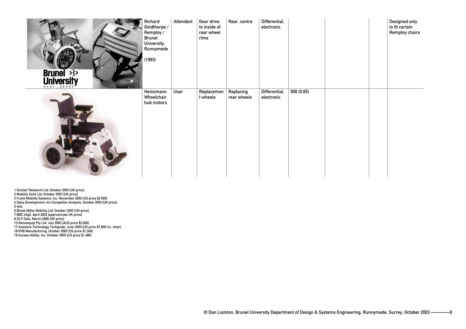
RichardGoldthorpe / Remploy / BrunelUniversity,Runnymede
(1993)
Attendant Gear drive to inside of rear wheel rims
Rear, centre Differential,electronic
Designed only to fit certain Remploy chairs
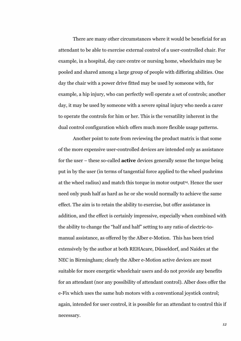
HeinzmannWheelchairhub motors
User Replacement wheels
Replacingrear wheels
Differential,electronic
500 (0.65)
1 Sinclair Research Ltd, October 2003 [UK price]2 Mobility Zone Ltd, October 2003 [UK price]3 Frank Mobility Systems, Inc, November 2002 [US price $2,500]4 Daka Development, Inc Competitor Analysis, October 2003 [UK price]5 ibid.6 Brook Miller Mobility Ltd, October 2003 [UK price]7 BBC h2g2, April 2003 [approximate UK price]8 DLF Data, March 2000 [UK price]13 Glennequip Pty Ltd, July 2003 [AUS price $2,000]17 Assistive Technology Techguide, June 2003 [US price $7,900 inc. chair]18 KVB Manufacturing, October 2003 [US price $1,349]19 Access-Ability, Inc, October 2003 [US price $1,485]

11
(1.2) Control
In broad terms, all the devices that have been produced fall into user
control, attendant control or dual control categories. The user & dual
control devices are generally more expensive than the simple attendant
control models — the cheapest attendant control model, the Sinclair ZA20
WDU, is £30511, whilst the cheapest user control model, the KVB Ramp
Runner, is the equivalent of £800 in the US, but is not sold in Britain12.
However, the Ramp Runner is perhaps a false “user control” model,
because it offers steering through the crudest possible method: the user
applies the brakes on the chair wheels (or holds the pushrims in opposition to
the motor) to effect differential steering action – something entirely possible
with the Sinclair unit, as with others such as the TGA13, but not recommended
by the manufacturers due to the forces and unpredictability involved.
Nevertheless, this is the steering method proposed by David Jackson’s
forthcoming Trevor Baylis Foundation Troll (see section 2.11), and the
effectiveness and feasibility of this was investigated as part of this project.
Dual control is the most versatile, since it allows either the user or an
attendant to control the chair; even if, in particular circumstances, it will
mainly be one or the other, this configuration still affords the possibility of
control by the other party where necessary. For example, if teaching a child
how to use his or her first powerchair, it would be essential for the parent or
carer to maintain some degree of control over the chair during the learning
phase, for safety reasons. The same applies with an add-on drive unit, even if,
once learned, the user always controls the chair thereon.
12
There are many other circumstances where it would be beneficial for an
attendant to be able to exercise external control of a user-controlled chair. For
example, in a hospital, day care centre or nursing home, wheelchairs may be
pooled and shared among a large group of people with differing abilities. One
day the chair with a power drive fitted may be used by someone with, for
example, a hip injury, who can perfectly well operate a set of controls; another
day, it may be used by someone with a severe spinal injury who needs a carer
to operate the controls for him or her. This is the versatility inherent in the
dual control configuration which offers much more flexible usage patterns.
Another point to note from reviewing the product matrix is that some
of the more expensive user-controlled devices are intended only as assistance
for the user – these so-called active devices generally sense the torque being
put in by the user (in terms of tangential force applied to the wheel pushrims
at the wheel radius) and match this torque in motor output14. Hence the user
need only push half as hard as he or she would normally to achieve the same
effect. The aim is to retain the ability to exercise, but offer assistance in
addition, and the effect is certainly impressive, especially when combined with
the ability to change the “half and half” setting to any ratio of electric-to-
manual assistance, as offered by the Alber e-Motion. This has been tried
extensively by the author at both REHAcare, Düsseldorf, and Naidex at the
NEC in Birmingham; clearly the Alber e-Motion active devices are most
suitable for more energetic wheelchair users and do not provide any benefits
for an attendant (nor any possibility of attendant control). Alber does offer the
e-Fix which uses the same hub motors with a conventional joystick control;
again, intended for user control, it is possible for an attendant to control this if
necessary.
13
(1.3) Drive
In terms of the actual method of drive, it can be seen that there are a number
of different configurations: extra drive wheels, roller drive (onto the
wheelchair tyres), drive onto geared rims on the wheels, and replacement
wheels. The majority of designs follow the path of offering replacement
wheels or extra wheels, but it is worth examining the other options as well.
Brunel Design student Richard Goldthorpe’s 1993 wheelchair drive15,
produced in conjunction with Remploy, used two pancake motors and
gearboxes to drive teeth fitted to the inside rims of the rear wheels of the
chair, with the 24V battery slung between the two motors across the width of
the rear of the chair. This unit was designed to provide attendant control (with
differential drive acting as steering); the intended market was elderly users.
Whether the idea of the geared rims was Goldthorpe’s or Remploy’s
is not recorded in his project report, but it is worth noting that there have
been patents for devices employing a similar drive method, e.g. Erwin Weisz’s
drive system shown in the product matrix16. In Remploy’s case, since
Goldthorpe’s wheelchair drive was intended to be supplied at the same time as
the user purchased the chair, as an OEM product, the extra expense of fitting
geared wheel rims of exactly the right size, or indeed replacing the wheels with
special ones, would not have the inconvenience factor associated with selling
the device as a ‘retro-fit’ third-party add-on. In terms of this project, though,
this method is not appropriate, and will not be further developed.

14
Replacement wheels, as offered by the Sunrise Quickie Powertec
models, fall into the same category in terms of being an “approved” power
conversion for a manual chair, supplied and designed by the original chair
manufacturer. The main disadvantage of these is that once fitted, the
conversion to powered operation is permanent, at least until the original (non-
powered) wheels are refitted. The Powertec’s wheels are too small to allow
manual propulsion if the motors fail, if the batteries run out, or if the user
desires some exercise. Alber’s e-Fix and e-Motion overcome these problems by
providing replacement wheels which retain all the manual propulsion
capabilities of standard, unpowered wheels, yet offer the power assistance in
an extremely compact package, with batteries and motors incorporated in the
wheel hubs. These are excellent products involving advanced technology,
which is reflected in the price.
Roller drive onto the wheelchair tyres is the preferred drive method
of a number of the products researched, all of which have apparently now
ceased production. In a sense, the concept is a pleasingly elegant one, since it
really is simply “motorising” an existing chair, with no additional wheels.
Indeed, when discussing this project with a technician (an alumnus of
Shoreditch College) at the Red Cross Daily Living Centre in Exeter, his first
suggestion was that this method of rollers in frictional contact with the tyres
was the most sensible solution.
In practice, however, this method has many failings. The author has not
inconsiderable experience with the Sinclair Zeta series of electric bicycle
drives (known as ZAP Zeta in the U.S.), which operated in this manner
(though using friction belts held against the tyre rather than simple rollers),
both as a user and latterly as a customer service manager dealing with the
15
many complaints received from buyers. The Zeta progressed through three
major design revisions, each time failing to address the most basic issue that a
vehicle tyre, whether on a wheelchair or a bicycle, is bound to become wet and
dirty in normal use, and any roller or belt driving directly onto it will require
the normal force holding it in frictional contact with the tyre surface to be
increased to compensate for the decrease in dynamic friction caused by the
wet surface. The Zeta in its final form used the weight of a lead-acid battery to
keep the belt pressed against the tyre, but even then, the result was not up to
the standards many customers expected. Slippage would occur in all but the
driest conditions, and if considerable sand or grit were picked up in the tyre
tread, the friction belt would become scored and consequently would wear out
more quickly.
In early post-war France, a petrol-engined device called the Velosolex17
gained some popularity; in a sense, this was similar, with a roller in frictional
contact driving the front tyre of a bicycle, but this had the considerable weight
of the engine to keep it in contact with the wheel, and perhaps it was a more
forgiving age in terms of reliability. A variant remains in production in
Hungary.
The best improvement in the field of frictional drive to vehicle tyres in
recent years is the Buzz, a novel mobility scooter manufactured by Suffolk-
based TGA Electric Leisure18 (also the manufacturers of the Wheelchair Power
Pack – see product matrix). This eschews conventional mobility scooter
transmission for a pair of hinged drive rollers onto large rear wheels,
controlled using levers positioned beside the user’s seat, so that he or she
drives forward by moving the levers to bring the rollers in contact with the
tyres, and steers differentially by lifting one roller away from the tyre whilst
16
leaving the other in contact. This apparently unconventional approach is
clearly more suited to someone who is merely frail rather than more seriously
disabled, since the twin-lever system requires two relatively (and equally)
strong arms. But the control method is quick to learn and has a particular
benefit in overcoming the Zeta’s problem by allowing the user (perhaps
subconsciously) to maintain the correct frictional contact between roller and
tyre, since if drive does not occur, the user will increase the force until it does.
In the author’s opinion, this is one of the most innovative mobility products
on the market at present, and scores highly above other mobility scooters in
allowing the user access to the seat (there are no front handlebars or column
to interfere). In testing it at the Naidex exhibition at the NEC, it was found to
be extremely manœuvrable (a castor front wheel with a long wheelbase makes
it somewhat similar to the Motivation three-wheeler chairs) and in giving the
user handles to grip, it restores some of the reassurance and feeling of safety
removed when the traditional handlebar layout is dispensed with.
Nevertheless, the consensus in wheelchair drive design has moved
away from the use of frictional drive, as can be seen by the dearth of current
products employing this method. A 1993 study of five different wheelchair
drives carried out by Gaal and Johnson, at San Francisco State University’s
Wheeled Mobility Centre, recommended that devices employing friction drive
against the wheelchair tyres “should either be avoided, or designed to be
largely insensitive to wet riding conditions.”19 As such, it was decided not to
pursue this drive method as a potential contender for this project.
Extra drive wheels, in various configurations, make up the majority
of the wheelchair drives currently available, and will prove to be the focus of
this project. The main benefits are that they allow the chair to be converted to

17
powered operation without needing modifications to the frame or removal of
the existing wheels; hence, the chair can (usually) be converted back to
manual propulsion by removing the drive unit. This allows the ultimate
versatility of being able to transfer one drive unit between multiple chairs,
particularly useful for hospitals or institutions where chairs are shared or used
by many different people with different needs and levels of ability.
Most of the extra wheel drive units which have been developed use
either one or two drive wheels, but one with a greater proliferation of wheels is
worthy of mention. The ATEC Swiss Trac is a four-wheeled motorised unit
which attaches with an articulated linkage to the front of a wheelchair, and is
steered by the user using the handlebars as a complete unit – similarly to how
the user would steer a rotovator or certain types of lawnmower. The Swiss
Trac affords impressive off-road capability, allowing wheelchair users freedom
that would be possible with neither a normal powerchair nor a self-propelled
chair.
The products using two drive wheels are worth comparing with those
using only one, since in most cases the twin wheels appear to be to offer
greater stability rather than any other advantage (for example differential
steering – see below). Clark mentions that Casali’s drive unit used (very small)
twin wheels because of the form factor it permitted (the right-angle gearbox
drive could be placed in between the wheels, with the motor above), thus
making the product into a more compact ‘bogie’, though it might be
considered that the lack of any differential or compensation for the
Ackermann effect when steering the drive wheels would lead to skipping and
excess tyre wear.

18
As the configuration with the most scope for development and
introduction of new ideas, and taking into account the experience gained with
the development and testing of the Sinclair unit, it was decided that this
project would involve a drive unit using either one or two drive wheels.
(1.4) Position
The existing products are split between front and rear mounting to the
wheelchair, with advantages and disadvantages pertinent to both
arrangements:
Strengths Weaknesses Conclusions
Rear mounting -Unimpededaccess to front of chair-Out of the way-Positioned where an attendant could easily control it
-Can be in way of attendant’s feet-Can tip user out of chair if geometry incorrect-Steering more of a challenge to effect
-Most popular arrangement for non-steerable drives, mostly using almost identical (‘sorted’) geometry-Worth pursuing
Front mounting -Steering easy to incorporate-Chair stability easier to control-Can provide safety reassurance to user through use of handlebars
-Can impede access to front of chair-If handlebars used, twisting of spine can be a problem for some-More difficult for an attendant to control
-More popular with ‘independent’ users, effectively turning wheelchair into a mobility scooter-Worth pursuing
Both arrangements were considered to be worth pursuing for this
project, since they both offer many advantages, and so it was decided to build
prototypes and test both configurations. This added a lot of complexity to the
development and prototyping process, but the result is a more carefully
considered design (similarly, perhaps, though on a less ambitious scale, to the
way that in considering the design of the new Mini, BMW commissioned both
front-engined, front-wheel drive, and rear-engined, rear-wheel drive designs
from the development teams, to allow a full comparison without prejudices20).

19
(1.5) Steering
Not all the models currently on sale offer steering, since in many cases (mostly
attendant-only devices), it is assumed that the attendant can manœuvre the
chair whilst under power by push/pull action on the handlebars on the rear of
the chair. Whilst this is of course possible, it may not be easy for a frail
attendant to manœuvre a chair with a heavy user in it, especially since in some
cases the wheel of the drive unit will be effectively operating in opposition to
the turning moment applied by the attendant. Turning a chair in this way also
twists the attendant’s spine to an unacceptable degree and can lead to severe
back pain; health and safety legislation has made electric ‘tugs’ almost
essential for moving heavy boxes and packaging in warehouses and factories;
yet many tens of thousands of carers, often elderly themselves, are every day
manœuvring heavy people in wheelchairs.
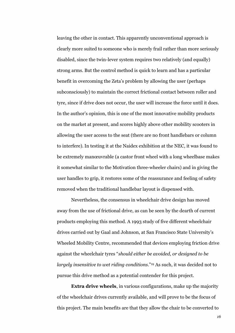
As already mentioned, the KVB Ramp Runner and forthcoming Trevor
Baylis Troll in its latest incarnation both rely on the user braking the wheel
pushrims by hand in order to effect steering (the drive unit offers only
straight-line drive), which was tested [Fig 1] for this project as a possible
steering method at a very early stage, using a Sinclair drive unit, and rejected
out of hand, since it was only easy at extremely low speeds and would hardly
be practical for someone with one arm weaker than the other, and would
require the use of gloves to lessen the risk of hand injury, quite apart from the
issue of how the user maintains control of the drive power while using his or
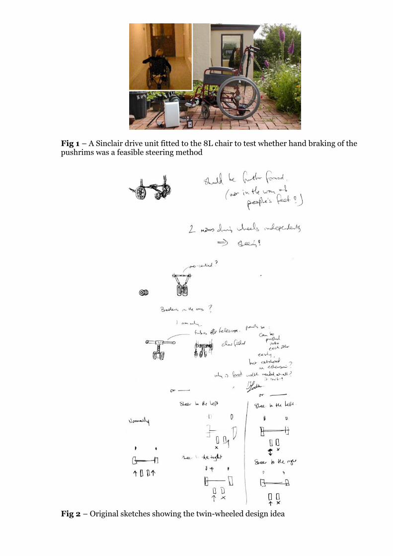
Fig 1 – A Sinclair drive unit fitted to the 8L chair to test whether hand braking of the pushrims was a feasible steering method
Fig 2 – Original sketches showing the twin-wheeled design idea
20
her hands to brake the wheel rims. In short, this is a very poor solution, and
offers no benefits to the user.
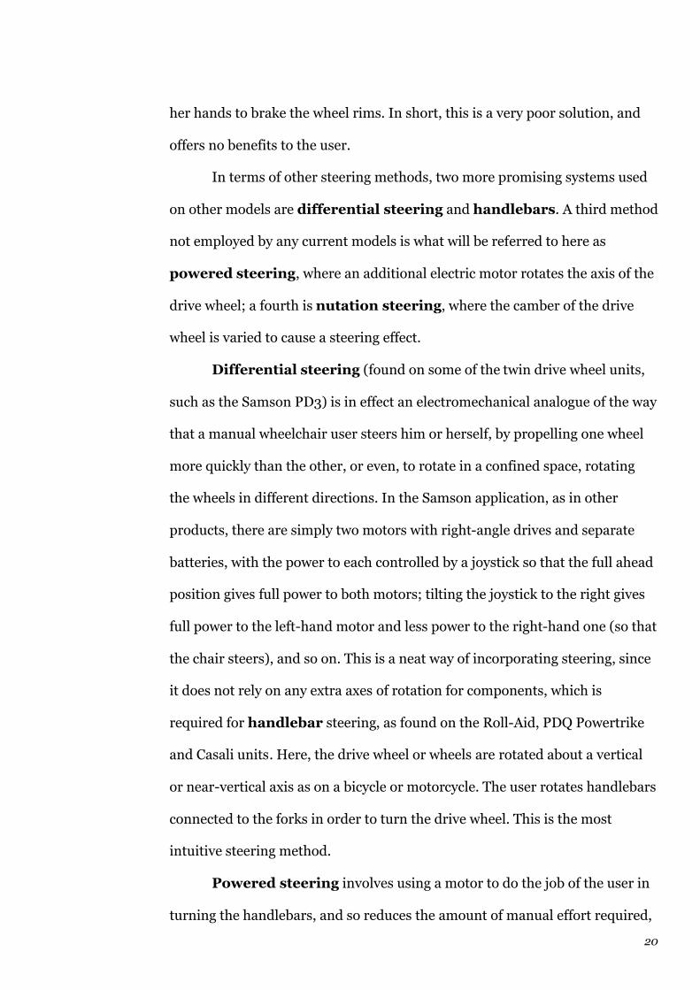
In terms of other steering methods, two more promising systems used
on other models are differential steering and handlebars. A third method
not employed by any current models is what will be referred to here as
powered steering, where an additional electric motor rotates the axis of the
drive wheel; a fourth is nutation steering, where the camber of the drive
wheel is varied to cause a steering effect.
Differential steering (found on some of the twin drive wheel units,
such as the Samson PD3) is in effect an electromechanical analogue of the way
that a manual wheelchair user steers him or herself, by propelling one wheel
more quickly than the other, or even, to rotate in a confined space, rotating
the wheels in different directions. In the Samson application, as in other
products, there are simply two motors with right-angle drives and separate
batteries, with the power to each controlled by a joystick so that the full ahead
position gives full power to both motors; tilting the joystick to the right gives
full power to the left-hand motor and less power to the right-hand one (so that
the chair steers), and so on. This is a neat way of incorporating steering, since
it does not rely on any extra axes of rotation for components, which is
required for handlebar steering, as found on the Roll-Aid, PDQ Powertrike
and Casali units. Here, the drive wheel or wheels are rotated about a vertical
or near-vertical axis as on a bicycle or motorcycle. The user rotates handlebars
connected to the forks in order to turn the drive wheel. This is the most
intuitive steering method.
Powered steering involves using a motor to do the job of the user in
turning the handlebars, and so reduces the amount of manual effort required,

21
whilst allowing single-wheel drive, which differential steering does not.
Nutation steering, best demonstrated by rolling a coin on a table and
watching it start to tilt, is effectively how a motorcyclist steers by leaning into
a corner: by inclining the wheel so that it describes a circle on the ground as it
rolls, rather than a straight line, steering is achieved.
All four steering methods were considered worth investigating for this
project.
(1.6) Wheelchair designs
There is an additional consideration in this project, since the drive unit under
development must be fitted to existing wheelchair designs. This may initially
be seen as a very large constraint, and indeed difficulty, since there is a
multitude of designs on the market from numerous manufacturers.
Nevertheless, the fact that very few of the existing wheelchair drives
prescribe fitting to only specific models of chair indicates that there is clearly
enough commonality among designs to permit a similar mode of attaching
and fitting the drive units, through adjustable fixings. From the author’s
experience with the Sinclair unit, it was found that by allowing a range of
adjustment in certain dimensions, the unit could be successfully fitted to a
wide variety of chair styles and sizes, reasonably quickly. The author was
required to demonstrate this at a number of shows and exhibitions.
To pursue this issue, a visit was made in October 2003 by Mark
Coleman and the author to the works of C. F Hewerdine Ltd, in Thorpe Lea.
22
Hewerdine is a mobility specialist with many decades of experience in the
field, and as well as supplying a range of chairs, both manual and powered, is
an approved contractor to the NHS for the reconditioning and repair of
wheelchairs in the home counties.
Geoffrey Gane, a director of Hewerdine, was extremely helpful21, and in
addition to confirming the belief that an add-on unit could easily be made to
fit most wheelchair designs on the market, he pointed out the relative ubiquity
of one basic design, in the UK and Commonwealth at least: the Remploy
8L/9L series. These models (the 8L is large-wheeled, self-propelled; the 9L is
small-wheeled, attendant/transit) share a common frame structure forward of
the rear wheel mounting. Remploy, originally a government initiative to
employ disabled ex-servicemen22, was set up in 1945, and for many years held
the entire NHS contract for wheelchair supply. The 8L and 9L, with
specialised variants (e.g. wider seat) were introduced in the late 1940s and
remain in production today. Since Remploy had effectively a monopoly on the
major channel of wheelchair supply for so many years in the UK, other
manufacturers such as Invacare chose to produce their own versions of the
8L/9L series, with the same dimensions and frame shape. Parts such as seat
cushions, castors, wheels and footrests are interchangeable. It is only in the
last 10 years or so that wheelchair design and availability have advanced from
the 8L/9L standard, with lightweight, aluminium-framed chairs now more
common. But these are expensive and often individually (privately) ordered
and built rather than being supplied through the NHS; Geoffrey Gane
estimated that up to 90% of wheelchairs in use in the UK are of the
8L/9L/variants pattern, and so any add-on drive unit which fitted these
models would have a large potential market.
23
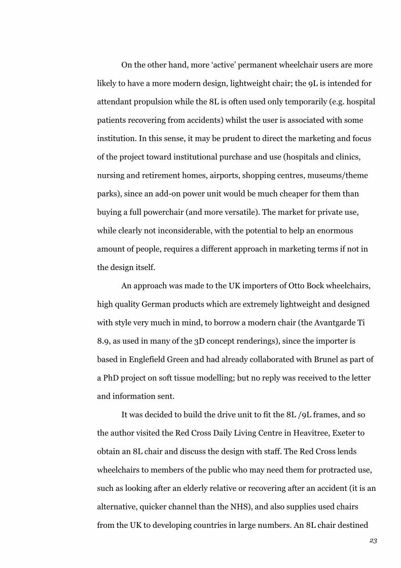
On the other hand, more ‘active’ permanent wheelchair users are more
likely to have a more modern design, lightweight chair; the 9L is intended for
attendant propulsion while the 8L is often used only temporarily (e.g. hospital
patients recovering from accidents) whilst the user is associated with some
institution. In this sense, it may be prudent to direct the marketing and focus
of the project toward institutional purchase and use (hospitals and clinics,
nursing and retirement homes, airports, shopping centres, museums/theme
parks), since an add-on power unit would be much cheaper for them than
buying a full powerchair (and more versatile). The market for private use,
while clearly not inconsiderable, with the potential to help an enormous
amount of people, requires a different approach in marketing terms if not in
the design itself.
An approach was made to the UK importers of Otto Bock wheelchairs,
high quality German products which are extremely lightweight and designed
with style very much in mind, to borrow a modern chair (the Avantgarde Ti
8.9, as used in many of the 3D concept renderings), since the importer is
based in Englefield Green and had already collaborated with Brunel as part of
a PhD project on soft tissue modelling; but no reply was received to the letter
and information sent.
It was decided to build the drive unit to fit the 8L /9L frames, and so
the author visited the Red Cross Daily Living Centre in Heavitree, Exeter to
obtain an 8L chair and discuss the design with staff. The Red Cross lends
wheelchairs to members of the public who may need them for protracted use,
such as looking after an elderly relative or recovering after an accident (it is an
alternative, quicker channel than the NHS), and also supplies used chairs
from the UK to developing countries in large numbers. An 8L chair destined

24
for Africa, manufactured in the 1970s and showing plenty of signs of wear and
heavy use, was purchased for a small donation. It was decided that a chair in
the kind of poor condition often encountered in hospitals and nursing homes
would be a better test of the competence of the drive unit than a brand new
one, since many potential users of the device would be fitting it to already
well-used chairs. The early acquisition of the chair (July 2003) enabled the
project to progress through a greater number of prototypes and test rigs than
would have been allowed by the nominal time-scale of the project.
(1.7) Wheelchair users and capabilities
To some extent all disability products must be individually tailored to the
user, since levels of ability vary enormously (often from day to day). A
nationwide network of occupational therapists and mobility advisors working
on behalf of the NHS and for charitable organisations recommends and
specifies the most suitable equipment (including wheelchairs) for individuals
after thorough examination of their needs and abilities. A detailed central
register of the equipment and variants available is maintained by the Disabled
Living Foundation23 and provided to OTs, doctors’ surgeries and clinics
around the country. The Hamilton Index, the core of “DLF Data” is in bound
volumes, but a CD-ROM and more recently, online versions have widened the
opportunities for spreading knowledge about some of the innovative and
potentially extremely useful products that are available, often from small,
specialist manufacturers.
There are many different reasons why someone may use a wheelchair,
and it is not always easy to discuss without tending towards stereotypes or
25
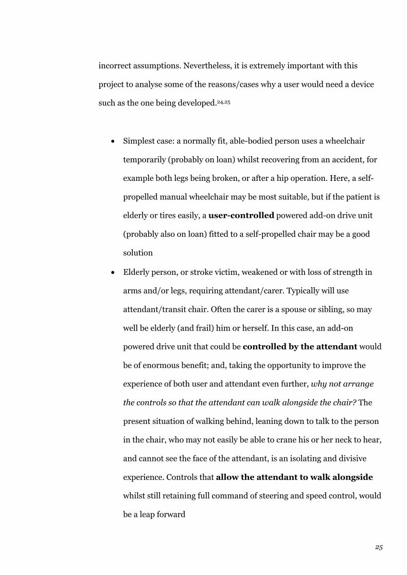
incorrect assumptions. Nevertheless, it is extremely important with this
project to analyse some of the reasons/cases why a user would need a device
such as the one being developed.24,25
• Simplest case: a normally fit, able-bodied person uses a wheelchair
temporarily (probably on loan) whilst recovering from an accident, for
example both legs being broken, or after a hip operation. Here, a self-
propelled manual wheelchair may be most suitable, but if the patient is
elderly or tires easily, a user-controlled powered add-on drive unit
(probably also on loan) fitted to a self-propelled chair may be a good
solution
• Elderly person, or stroke victim, weakened or with loss of strength in
arms and/or legs, requiring attendant/carer. Typically will use
attendant/transit chair. Often the carer is a spouse or sibling, so may
well be elderly (and frail) him or herself. In this case, an add-on
powered drive unit that could be controlled by the attendant would
be of enormous benefit; and, taking the opportunity to improve the
experience of both user and attendant even further, why not arrange
the controls so that the attendant can walk alongside the chair? The
present situation of walking behind, leaning down to talk to the person
in the chair, who may not easily be able to crane his or her neck to hear,
and cannot see the face of the attendant, is an isolating and divisive
experience. Controls that allow the attendant to walk alongside
whilst still retaining full command of steering and speed control, would
be a leap forward

26
• Amputees may have superb upper body strength and physical fitness,
but may still need a wheelchair; even if they have artificial limbs, it may
be extremely tiring to walk long distances with them. Typically a
younger, fitter amputee may use a lightweight self-propelled chair with
inclined wheels to give greater stability; but that does not mean that he
or she would not enjoy and benefit from a user-controlled powered
drive unit in some situations, for example slopes and ramps. In cases
where one arm has been amputated and the user has a wheelchair (a
leg may be amputated too), it is important that the drive unit can be
controlled properly using only one hand.
• Users who choose to use a wheelchair occasionally due to ‘functional
decline’ conditions of old age, e.g. arthritis, poor balance, aching legs,
etc. This is usually the market for mobility scooters: people who can
walk short distances, but find it gives them more freedom if using a
powered device (or with someone pushing). This may prove to be a
market where a user-controlled powered add-on drive unit for a
wheelchair could be a useful addition, since a wheelchair is usually
lighter weight (hence easier to transport in a car boot) and more
manœuvrable than a mobility scooter, as well as potentially safer due to
the lower centre of gravity
• C7-8 tetraplegics (quadriplegics): where a spinal cord injury in the
lower levels of the cervical vertebræ (neck) results in paralysis from the
neck down, but with some function and strength in the arms. Hand
control may be poor, but the user may be able to propel and manœuvre
a manual chair proficiently. A user-controlled power drive with
simple, easy controls would be suitable. Ideally the controls would be

27
able to be set at the desired speed in a cruise-control manner so
that the user does not have to make too many adjustments. However, a
full powerchair is at present most likely to be specified by an OT
• T1-12 paraplegics: where a spinal cord injury in the upper back
(thoracic) results in total or partial paralysis of the legs and or lower
torso area but leaves the arms functioning. A T1 paraplegic (where the
first, i.e. highest thoracic vertebra has a working nerve root, but
everything below it is non-functional) may have problems with hand
control movements, so whilst he or she may use a manual wheelchair,
there may be the need for handgrips on the pushrims. T-paraplegics
often suffer from loss of strength due to torso paralysis, so may have
trouble lifting heavy devices or twisting handlebars. In terms of an add-
on drive, a user-controlled unit is the most appropriate, though
some users may have sufficient strength to need it only occasionally
• L1-5 & S1-2 paraplegics: spinal cord injuries to the lumbar (lower back)
and sacral vertebræ mean that these users may be able to walk, with
varying levels of ability, yet many will still use a wheelchair (usually
manual), especially as they grow older. A user-controlled power unit
would be a welcome aid
• Muscle paralysis, weakness and control conditions such as muscular
dystrophy, multiple sclerosis, cerebral palsy and polio (now rare) vary
considerably in their severity from person to person, but clearly there
will be many sufferers who currently use a manual wheelchair and
would benefit from a user-controlled power unit
• Young children with any one of the above problems will most likely be
looked after, certainly out of doors by a parent or carer even if

28
physically capable of propelling themselves, due to the issues of safety.
While a child learns to control and manipulate a wheelchair, he or she
may need a lot of help, especially if it is a powerchair, so a dual-
control system is the ideal. As a child grows, his or her wheelchair
may have to be replaced every few years, and if it is a full powerchair,
this could prove extremely costly. A transferable power drive unit
which could be fitted to multiple chairs makes a lot more sense
Thus the potential users of the wheelchair drive are a varied mix of old and
young, able and not-so-able. What became clear is that the unit needed to be
extremely versatile, and these considerations were incorporated into the
specification.
At the initial stage, the specification did not incorporate any technical
or mechanical requirements or configurations, since it was felt that these
would arise from the development phase of the project and to direct the
project down any particular lines at an early stage would not be helpful.
29
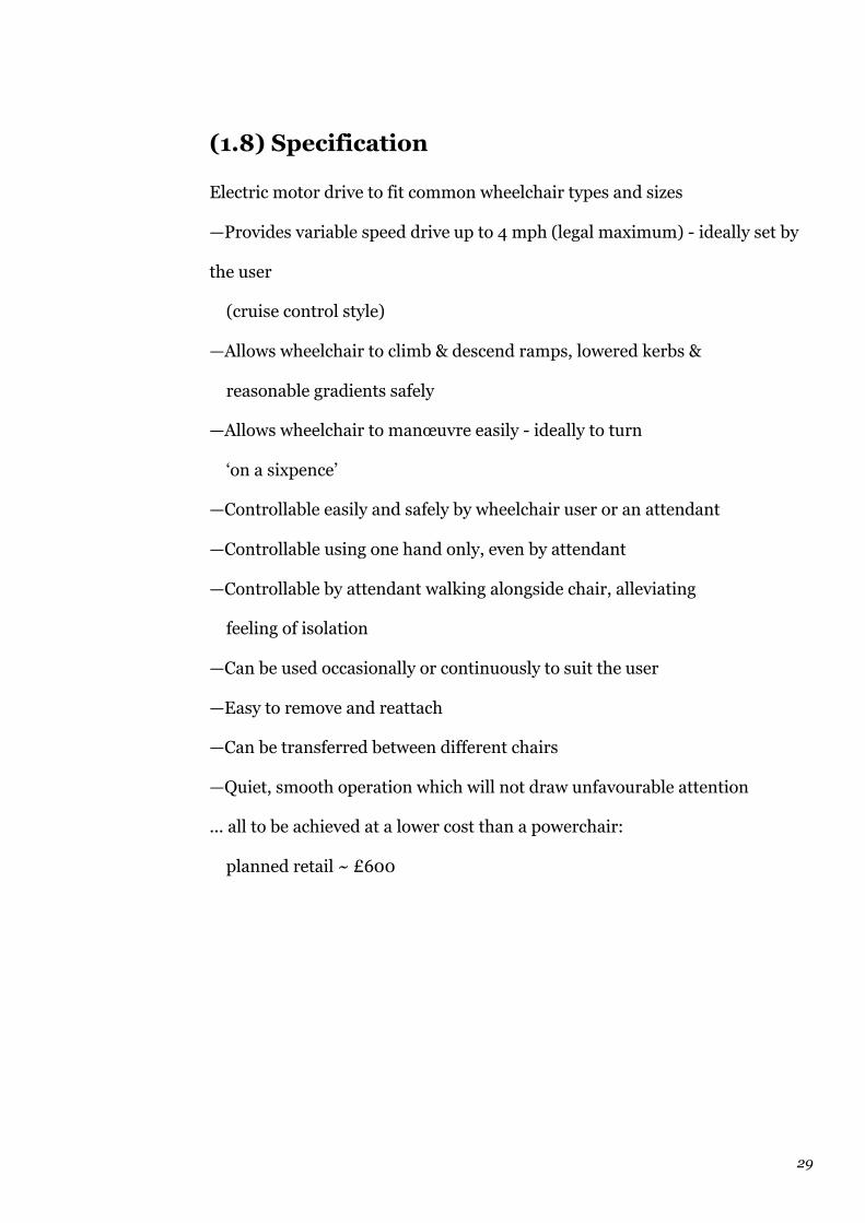
(1.8) Specification
Electric motor drive to fit common wheelchair types and sizes
—Provides variable speed drive up to 4 mph (legal maximum) - ideally set by
the user
(cruise control style)
—Allows wheelchair to climb & descend ramps, lowered kerbs &
reasonable gradients safely
—Allows wheelchair to manœuvre easily - ideally to turn
‘on a sixpence’
—Controllable easily and safely by wheelchair user or an attendant
—Controllable using one hand only, even by attendant
—Controllable by attendant walking alongside chair, alleviating
feeling of isolation
—Can be used occasionally or continuously to suit the user
—Easy to remove and reattach
—Can be transferred between different chairs
—Quiet, smooth operation which will not draw unfavourable attention
... all to be achieved at a lower cost than a powerchair:
planned retail ~ £600
30
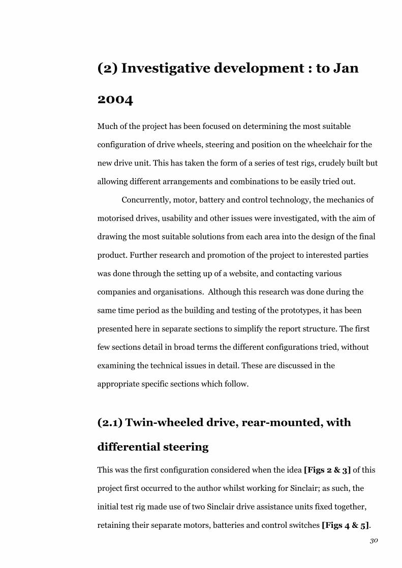
(2) Investigative development : to Jan
2004
Much of the project has been focused on determining the most suitable
configuration of drive wheels, steering and position on the wheelchair for the
new drive unit. This has taken the form of a series of test rigs, crudely built but
allowing different arrangements and combinations to be easily tried out.
Concurrently, motor, battery and control technology, the mechanics of
motorised drives, usability and other issues were investigated, with the aim of
drawing the most suitable solutions from each area into the design of the final
product. Further research and promotion of the project to interested parties
was done through the setting up of a website, and contacting various
companies and organisations. Although this research was done during the
same time period as the building and testing of the prototypes, it has been
presented here in separate sections to simplify the report structure. The first
few sections detail in broad terms the different configurations tried, without
examining the technical issues in detail. These are discussed in the
appropriate specific sections which follow.
(2.1) Twin-wheeled drive, rear-mounted, with
differential steering
This was the first configuration considered when the idea [Figs 2 & 3] of this
project first occurred to the author whilst working for Sinclair; as such, the
initial test rig made use of two Sinclair drive assistance units fixed together,
retaining their separate motors, batteries and control switches [Figs 4 & 5].

Fig 3 – Original sketches showing the twin-wheeled design idea
Fig 4 – Twin-wheeled prototypes
Fig 5 – Twin-wheeled prototypes
31
The user had two switches on cables routed through the frame to a
comfortable position; to drive forward, both switches were pressed, while
releasing one effected steering. The drive units were fitted to the rear frame of
the chair, behind the seat, in much the same position as most of the (single-
wheeled, non-steering) wheelchair drives on the market.
In testing this arrangement, it was found that as initially positioned,
the steering effect was poor on most surfaces; the chair tended to skip
sideways rather than turn smoothly if the wheels had any freedom to slide
(e.g. loose chippings on tarmac). In addition, the fact that the Sinclair units
did not provide for any reversed drive direction meant that the desired
“turning on a sixpence” was not achieved.
An improved version was constructed [Fig 6], still using the motors
and gearboxes from two Sinclair drive units, but with larger drive wheels [Fig
7] (a bogie from a pushchair) and a common battery for the two motors to
reduce the amount of space required [Fig 8]. This was all housed in a casing,
with a longer arm protruding to allow mounting to the chair further behind
than the previous rig. The aim of this was to increase the turning moment
provided by the steering. This prototype also included a reversing function for
each motor so that the steering range would be increased. Again, though, the
effect was found to be poor. It was concluded that the driven wheels really
needed to be further apart as well as further back in order to give a satisfactory
steering effect, but this would make for a very bulky (or certainly not compact)
drive unit, with problems manœuvring in confined spaces (see Usability
discussion below).
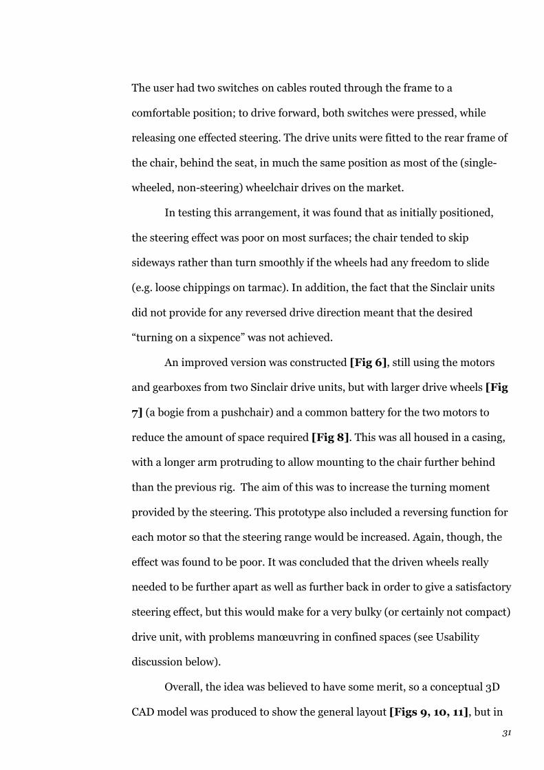
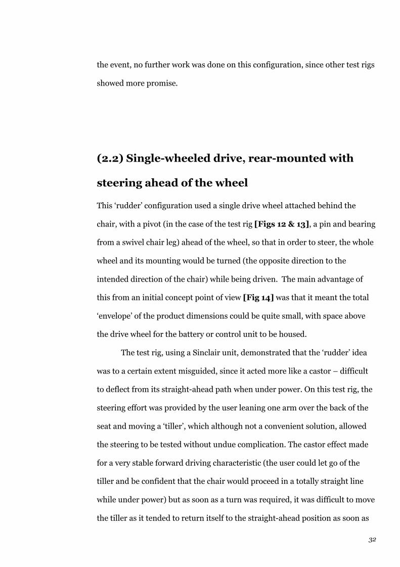
Overall, the idea was believed to have some merit, so a conceptual 3D
CAD model was produced to show the general layout [Figs 9, 10, 11], but in

Fig 6 – Twin-wheeled prototypes
Fig 7 – Twin-wheeled prototypes
Fig 8 – Twin-wheeled prototypes
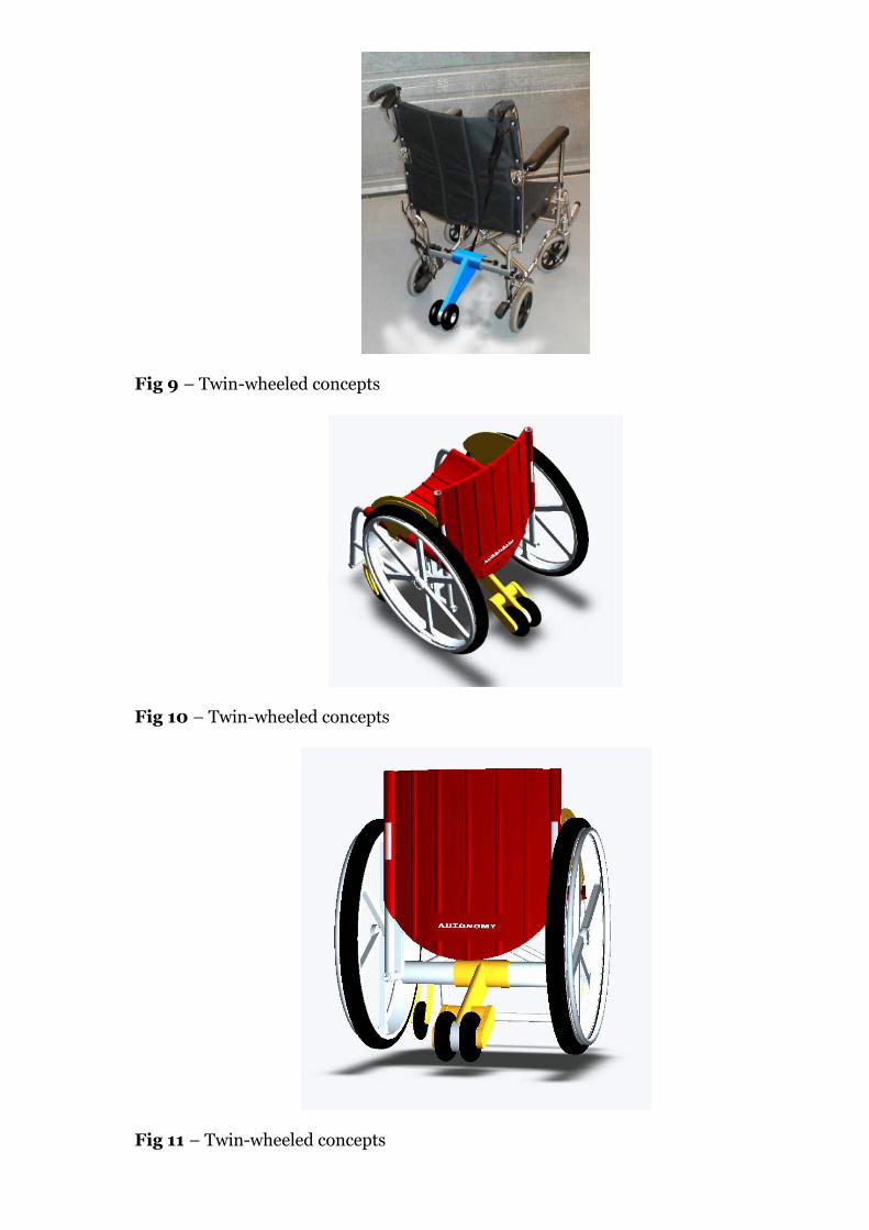
Fig 9 – Twin-wheeled concepts
Fig 10 – Twin-wheeled concepts
Fig 11 – Twin-wheeled concepts
32
the event, no further work was done on this configuration, since other test rigs
showed more promise.
(2.2) Single-wheeled drive, rear-mounted with
steering ahead of the wheel
This ‘rudder’ configuration used a single drive wheel attached behind the
chair, with a pivot (in the case of the test rig [Figs 12 & 13], a pin and bearing
from a swivel chair leg) ahead of the wheel, so that in order to steer, the whole
wheel and its mounting would be turned (the opposite direction to the
intended direction of the chair) while being driven. The main advantage of
this from an initial concept point of view [Fig 14] was that it meant the total
‘envelope’ of the product dimensions could be quite small, with space above
the drive wheel for the battery or control unit to be housed.
The test rig, using a Sinclair unit, demonstrated that the ‘rudder’ idea
was to a certain extent misguided, since it acted more like a castor – difficult
to deflect from its straight-ahead path when under power. On this test rig, the
steering effort was provided by the user leaning one arm over the back of the
seat and moving a ‘tiller’, which although not a convenient solution, allowed
the steering to be tested without undue complication. The castor effect made
for a very stable forward driving characteristic (the user could let go of the
tiller and be confident that the chair would proceed in a totally straight line
while under power) but as soon as a turn was required, it was difficult to move
the tiller as it tended to return itself to the straight-ahead position as soon as
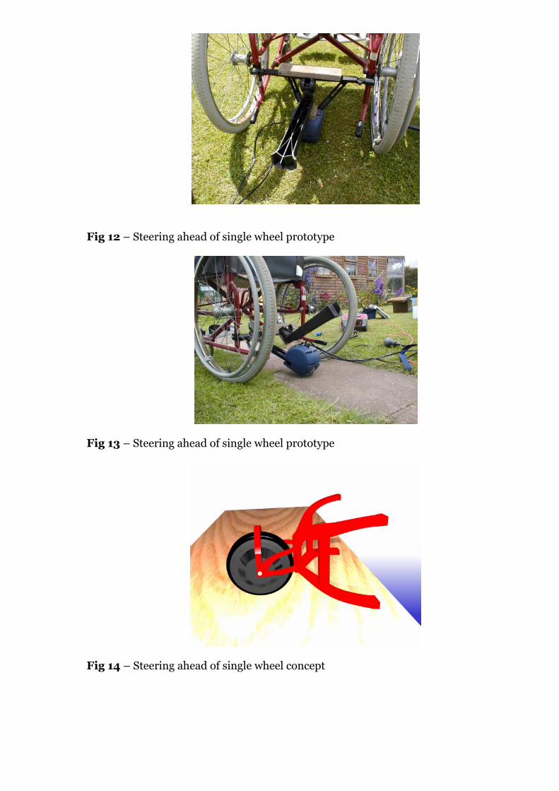
Fig 12 – Steering ahead of single wheel prototype
Fig 13 – Steering ahead of single wheel prototype
Fig 14 – Steering ahead of single wheel concept

33
possible. Clearly, this system would be much better employed in a higher
speed application where larger radius turns are desired, rather than a product
intended to turn on the spot; and indeed, the castor action engineered into the
steering of some front-wheel drive three-wheeled cars, such as the Bond
Minicar and a 1950s Pashley design made for much safer handling at road
speeds. These vehicles overcame some of the castor effect where it was not
desired (i.e. at low speeds) by including a deliberately low efficiency gearbox
in the steering, so that the driver’s steering wheel would not immediately
unwind every time he or she turned it to deflect the wheel from the straight-
ahead position. It would be possible to incorporate this (highly geared steering
– or even irreversible) in the wheelchair drive, and indeed this was later tested
when the powered steering was under development (see section 2.3) .
A variety of 3D CAD models were produced to show the general layout
[Figs 15-18] of the basic configuration; these show the use of a hub motor
(see the later discussion of Motors).
(2.3) Single-wheeled drive, rear-mounted with
steering above the wheel
Here the steering axis of the drive wheel was coincident with a diameter of
that wheel (though not necessarily completely vertical) and the drive wheel
was mounted behind the chair, with enough space to rotate 90 degrees either
side of the original position. The intention was to incorporate powered
steering into this arrangement eventually [Fig 19] and, in conjunction with
using a hub motor for the driven wheel (see Motors discussion), had the
potential to produce an extremely neat and compact product [Figs 20-22].
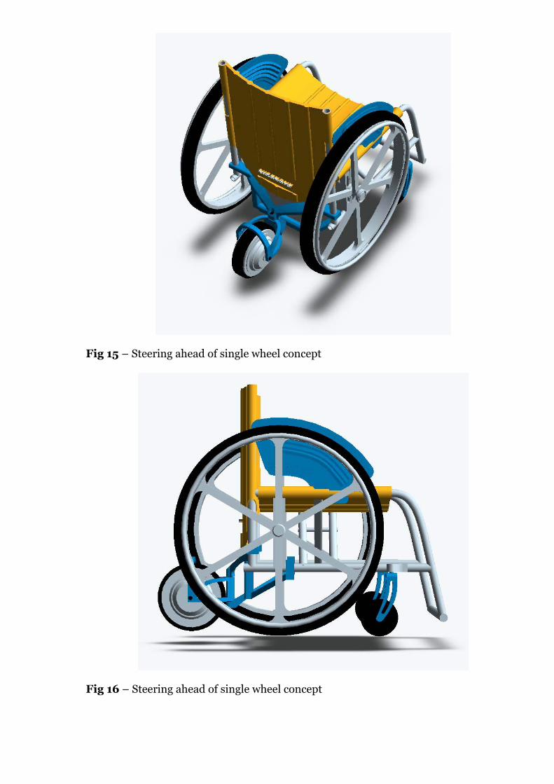
Fig 15 – Steering ahead of single wheel concept
Fig 16 – Steering ahead of single wheel concept
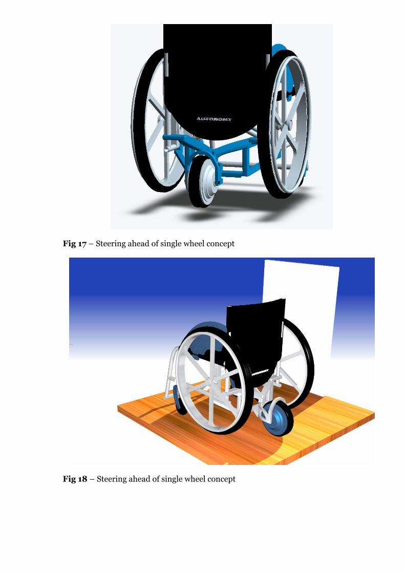
Fig 17 – Steering ahead of single wheel concept
Fig 18 – Steering ahead of single wheel concept
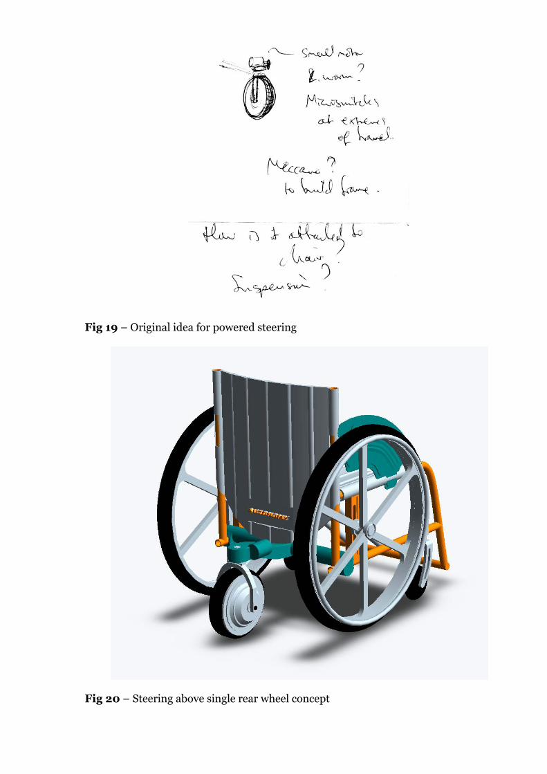
Fig 19 – Original idea for powered steering
Fig 20 – Steering above single rear wheel concept
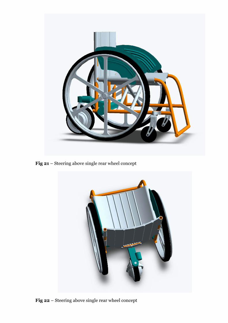
Fig 21 – Steering above single rear wheel concept
Fig 22 – Steering above single rear wheel concept

34
The first test rig [Figs 23-26] used a Sinclair drive unit mounted
rotatably to a frame extending from the back of the chair, and steerable by the
user again using effectively a tiller arrangement (in this case the two mounting
arms extending from the drive unit). This proved very successful in
manœuvring the chair as well as driving in a straight line; it was able to spin
the chair on the spot on the level, though had trouble when on a cambered
road surface. The frame arrangement used meant that there was no inherent
downward thrust on the wheel, so to overcome wheelspin, the user had to
press down on the frame to keep the wheel in full contact with the ground;
nevertheless, this looked a promising configuration to develop.
The next stage in developing this idea was to incorporate the Golden
Island brushless hub motor (see Motors discussion) which provided much
more power than the Sinclair unit (450 W maximum as opposed to 200W),
had a much larger wheel and the weight required to improve traction. Initially
this was tested with a rigid arrangement without a steering function (see
Motors discussion), but manually operated steering was then incorporated
using the front forks from a Raleigh Burner and head tube from a Raleigh
Equipe [Figs 27 & 28], fitted behind the chair. This was a neat way to
achieve the required function without extra fabrication being required, and
allowed different frame structures to be investigated for attaching the device
to the chair and transmitting the forces. The initial T-bar frame was
extensively tested outdoors and did not prove rigid enough to withstand the
turning moments encountered when steering at 90 degrees to the forward
position, so a stiffened arrangement using angled steel shelf brackets bolted to
an aluminium extrusion cross-piece was tried [Figs 29-38]. This was more
successful; a triangulated arrangement [Fig 39] was the stiffest, as would be
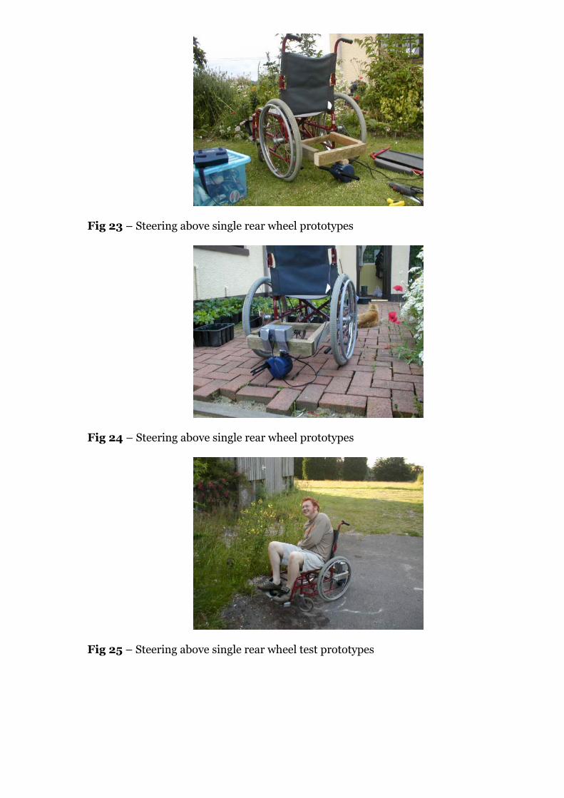
Fig 23 – Steering above single rear wheel prototypes
Fig 24 – Steering above single rear wheel prototypes
Fig 25 – Steering above single rear wheel test prototypes

Fig 26 – Steering above single rear wheel test prototypes
Fig 27 – Steering above single rear wheel Golden Island Motor prototypes
Fig 28 – Steering above single rear wheel Golden Island Motor prototypes

Fig 29 – Steering above single rear wheel Golden Island Motor prototypes
Fig 30 – Steering above single rear wheel Golden Island Motor prototypes

Fig 31 – Steering above single rear wheel Golden Island Motor prototypes
Fig 32 – Steering above single rear wheel Golden Island Motor prototypes
Fig 33 – Steering above single rear wheel Golden Island Motor prototypes
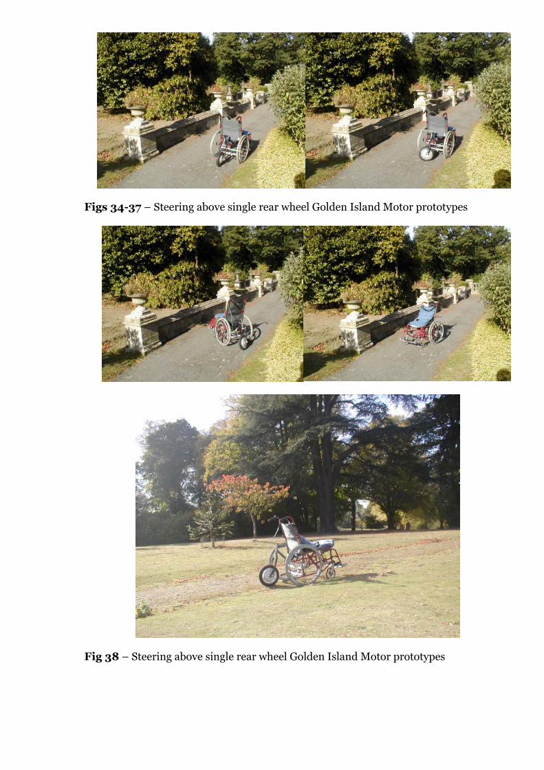
Figs 34-37 – Steering above single rear wheel Golden Island Motor prototypes
Fig 38 – Steering above single rear wheel Golden Island Motor prototypes

35
expected, but took up a lot of space. Throughout these tests, the prototype was
fixed to the vertical rear frame members of the wheelchair using flexible
injection-moulded plastic clamps from the Sinclair drive unit, mainly for
convenience since these were easy to tighten using an Allen key and their
position on the chair could be adjusted quickly.
On these prototypes, the manual steering was again effectively a tiller
arrangement, using either a right-angled arm fitted into a slot in the top end
of the fork tube, or an empty Sinclair drive unit casing acting as a chunky
‘handle’, with one of the mounting arms wedged into the end of the fork tube.
One conclusion drawn from this phase of testing was that the size of the
apparatus was much too large – it was awkward having a 12” wheel sticking
out of the back of the chair, and made manœuvring in confined spaces
difficult. This (confirmed by comments posted on the website message board)
was one of the factors behind the decision to try an alternative type of hub
motor (see Motors discussion), and the acquisition of the new XTi motor
meant that a much more compact device could be designed, initially using the
motor connected directly to two 12V batteries with a rotary potentiometer as a
speed controller, but later replaced by a more suitable 4QD pulse-width
modulated controller (see Control Technology section).
This next round of prototypes was designed to incorporate powered
steering from the start. A heavy-duty castor from an industrial waste bin was
cut down and used as the basis for the steering, with slimline steel forks from
a Raleigh Equipe bicycle holding the motorised wheel and adjustably attached
to the castor body using aluminium box-section [Fig 40]. The initial plan was
to attach this to another piece of (larger) aluminium section [Figs 41-44]
which would house the battery, as well as providing much better stiffness and
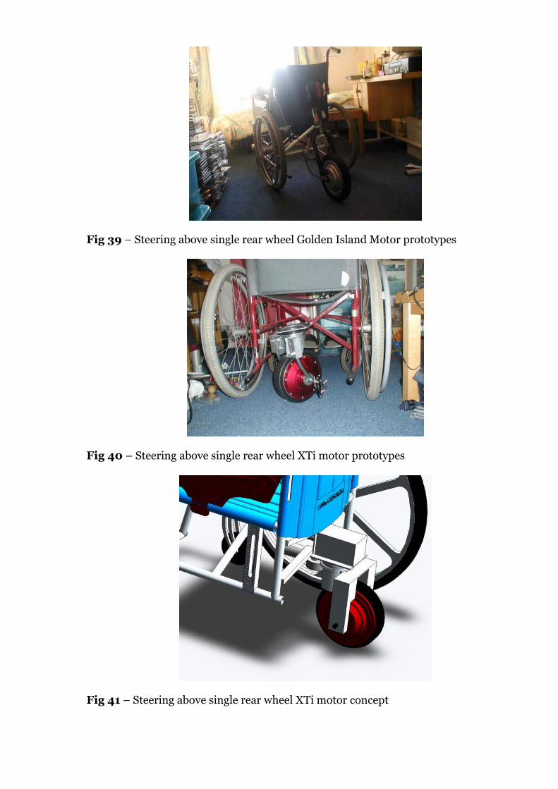
Fig 39 – Steering above single rear wheel Golden Island Motor prototypes
Fig 40 – Steering above single rear wheel XTi motor prototypes
Fig 41 – Steering above single rear wheel XTi motor concept

Fig 42 – Steering above single rear wheel XTi motor concept
Fig 43 – Steering above single rear wheel XTi motor concept
Fig 44 – Steering above single rear wheel XTi motor concept
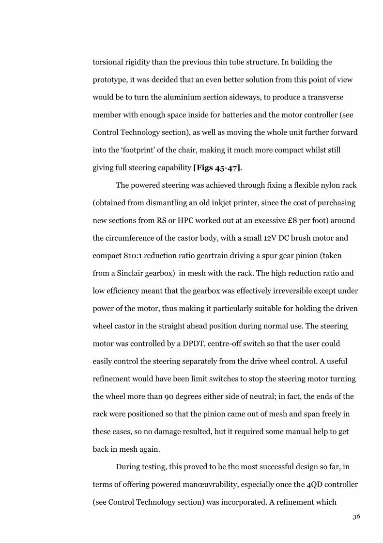
36
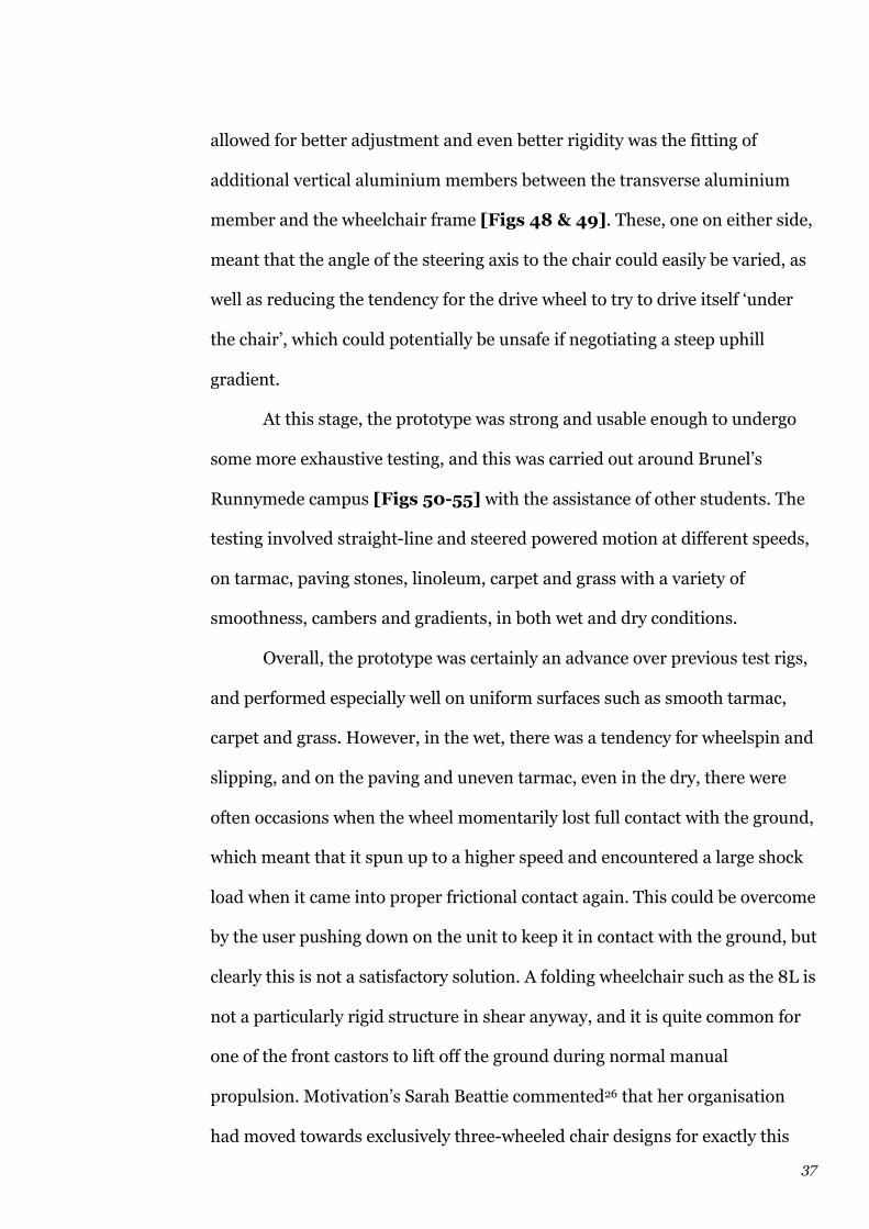
torsional rigidity than the previous thin tube structure. In building the
prototype, it was decided that an even better solution from this point of view
would be to turn the aluminium section sideways, to produce a transverse
member with enough space inside for batteries and the motor controller (see
Control Technology section), as well as moving the whole unit further forward
into the ‘footprint’ of the chair, making it much more compact whilst still
giving full steering capability [Figs 45-47].
The powered steering was achieved through fixing a flexible nylon rack
(obtained from dismantling an old inkjet printer, since the cost of purchasing
new sections from RS or HPC worked out at an excessive £8 per foot) around
the circumference of the castor body, with a small 12V DC brush motor and
compact 810:1 reduction ratio geartrain driving a spur gear pinion (taken
from a Sinclair gearbox) in mesh with the rack. The high reduction ratio and
low efficiency meant that the gearbox was effectively irreversible except under
power of the motor, thus making it particularly suitable for holding the driven
wheel castor in the straight ahead position during normal use. The steering
motor was controlled by a DPDT, centre-off switch so that the user could
easily control the steering separately from the drive wheel control. A useful
refinement would have been limit switches to stop the steering motor turning
the wheel more than 90 degrees either side of neutral; in fact, the ends of the
rack were positioned so that the pinion came out of mesh and span freely in
these cases, so no damage resulted, but it required some manual help to get
back in mesh again.
During testing, this proved to be the most successful design so far, in
terms of offering powered manœuvrability, especially once the 4QD controller
(see Control Technology section) was incorporated. A refinement which
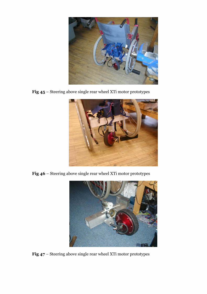
Fig 45 – Steering above single rear wheel XTi motor prototypes
Fig 46 – Steering above single rear wheel XTi motor prototypes
Fig 47 – Steering above single rear wheel XTi motor prototypes
37
allowed for better adjustment and even better rigidity was the fitting of
additional vertical aluminium members between the transverse aluminium
member and the wheelchair frame [Figs 48 & 49]. These, one on either side,
meant that the angle of the steering axis to the chair could easily be varied, as
well as reducing the tendency for the drive wheel to try to drive itself ‘under
the chair’, which could potentially be unsafe if negotiating a steep uphill
gradient.
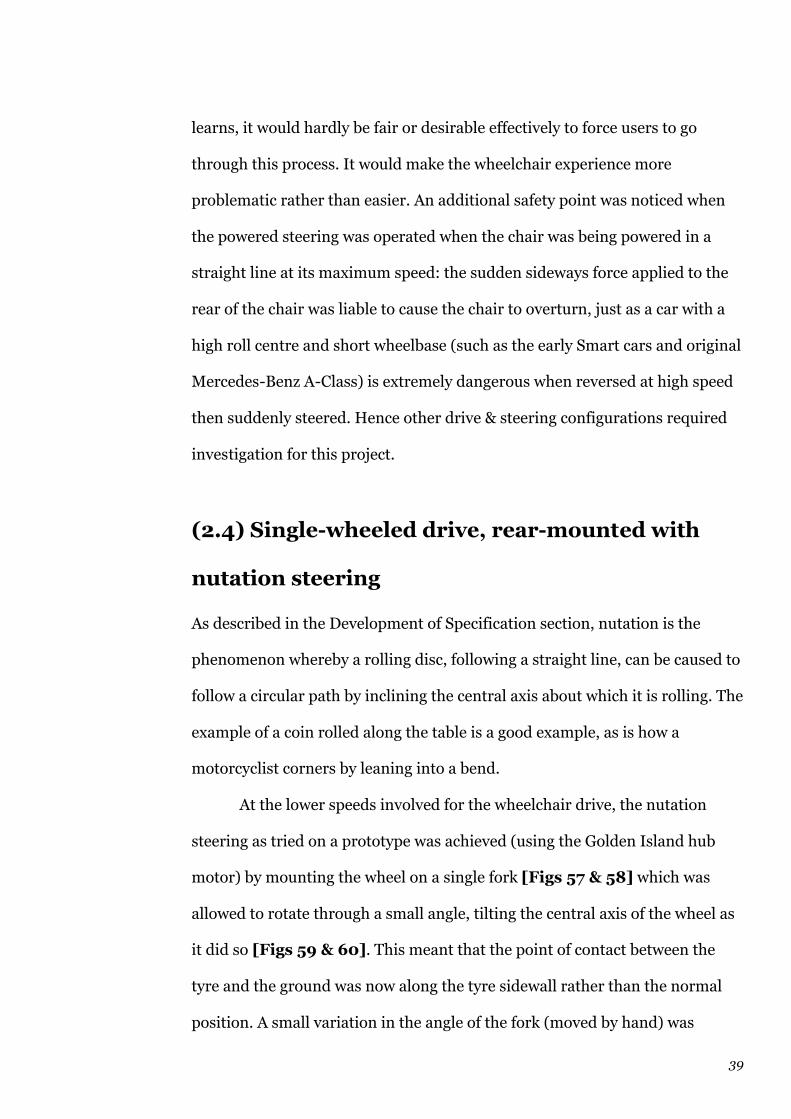
At this stage, the prototype was strong and usable enough to undergo
some more exhaustive testing, and this was carried out around Brunel’s
Runnymede campus [Figs 50-55] with the assistance of other students. The
testing involved straight-line and steered powered motion at different speeds,
on tarmac, paving stones, linoleum, carpet and grass with a variety of
smoothness, cambers and gradients, in both wet and dry conditions.
Overall, the prototype was certainly an advance over previous test rigs,
and performed especially well on uniform surfaces such as smooth tarmac,
carpet and grass. However, in the wet, there was a tendency for wheelspin and
slipping, and on the paving and uneven tarmac, even in the dry, there were
often occasions when the wheel momentarily lost full contact with the ground,
which meant that it spun up to a higher speed and encountered a large shock
load when it came into proper frictional contact again. This could be overcome
by the user pushing down on the unit to keep it in contact with the ground, but
clearly this is not a satisfactory solution. A folding wheelchair such as the 8L is
not a particularly rigid structure in shear anyway, and it is quite common for
one of the front castors to lift off the ground during normal manual
propulsion. Motivation’s Sarah Beattie commented26 that her organisation
had moved towards exclusively three-wheeled chair designs for exactly this

Fig 48 – Steering above single rear wheel XTi motor prototypes
Fig 49 – Steering above single rear wheel XTi motor prototypes
Fig 50 – Steering above single rear wheel XTi motor prototypes

Fig 51 – Steering above single rear wheel XTi motor prototypes
Fig 52 – Steering above single rear wheel XTi motor prototypes
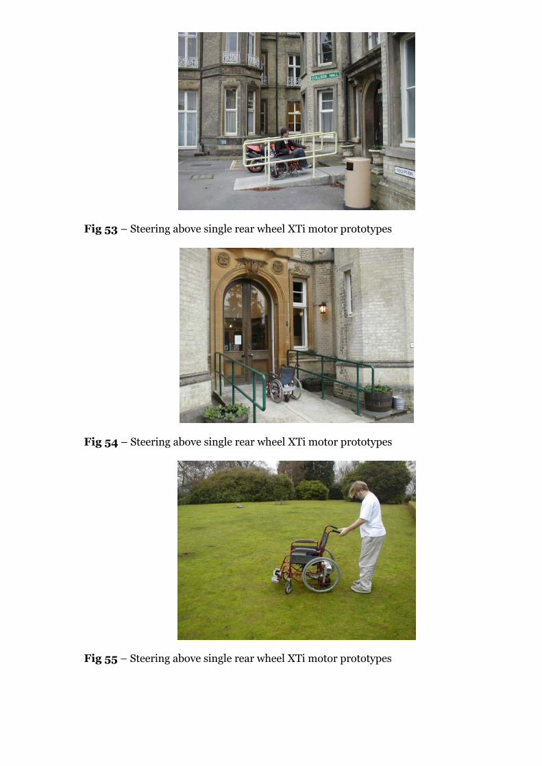
Fig 53 – Steering above single rear wheel XTi motor prototypes
Fig 54 – Steering above single rear wheel XTi motor prototypes
Fig 55 – Steering above single rear wheel XTi motor prototypes

38
‘four-legged stool is never stable’ reason, and in adding a fifth wheel in contact
with the ground, it was bound to make the situation worse. Solutions such as a
spring holding the wheel in contact with the ground were considered but not
pursued at this stage.
The powered steering proved to work well in mechanical terms, but as
rear-wheel steering along the lines of a fork-lift truck’s, it was very difficult for
the user to predict exactly the amount of turn needed to negotiate a bend or
obstruction in the path. Particularly troublesome was turning around in a
corridor or other narrow space, whether a full U-turn or a three-point turn. To
accomplish this successfully with rear-wheel steering and castor front wheels
on the chair involves making sure there is enough clearance between the side
of the chair and the wall, since the rear will swing out in this direction in order
to move the front in the other direction [Fig 56]. This removed much of the
utility of the steering and meant that the user would have to keep a very
careful eye on exactly what he or she was doing; trying to turn a corner as one
passed through a doorway would be very difficult without the rear of the chair
scraping the door. Clearly many disabled people would find it difficult to twist
their body to watch out for clearances on the side of the chair, and unless
some kind of indicator display were fitted ahead of the user, in normal line of
sight, showing what was happening to the back of the chair, this would not be
a pleasant steering method to use.
This was a difficult conclusion to reach at this stage of the project, since
so much effort had gone into investigating and testing rear-steered layouts,
but it was inescapable that this layout had many flaws from a usability point of
view: whilst users could certainly learn, in time, how to operate the steering
successfully in all manner of tight situations, just as a fork-lift truck driver
39
learns, it would hardly be fair or desirable effectively to force users to go
through this process. It would make the wheelchair experience more
problematic rather than easier. An additional safety point was noticed when
the powered steering was operated when the chair was being powered in a
straight line at its maximum speed: the sudden sideways force applied to the
rear of the chair was liable to cause the chair to overturn, just as a car with a
high roll centre and short wheelbase (such as the early Smart cars and original
Mercedes-Benz A-Class) is extremely dangerous when reversed at high speed
then suddenly steered. Hence other drive & steering configurations required
investigation for this project.
(2.4) Single-wheeled drive, rear-mounted with
nutation steering
As described in the Development of Specification section, nutation is the
phenomenon whereby a rolling disc, following a straight line, can be caused to
follow a circular path by inclining the central axis about which it is rolling. The
example of a coin rolled along the table is a good example, as is how a
motorcyclist corners by leaning into a bend.
At the lower speeds involved for the wheelchair drive, the nutation
steering as tried on a prototype was achieved (using the Golden Island hub
motor) by mounting the wheel on a single fork [Figs 57 & 58] which was
allowed to rotate through a small angle, tilting the central axis of the wheel as
it did so [Figs 59 & 60]. This meant that the point of contact between the
tyre and the ground was now along the tyre sidewall rather than the normal
position. A small variation in the angle of the fork (moved by hand) was
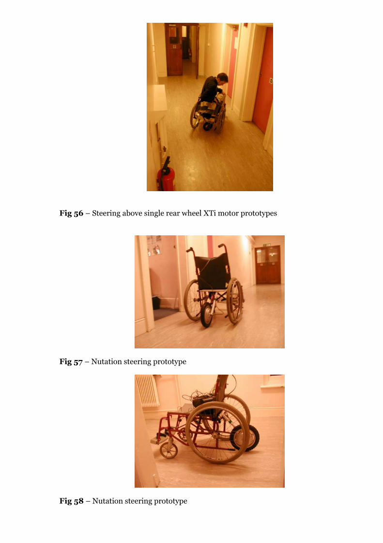
Fig 56 – Steering above single rear wheel XTi motor prototypes
Fig 57 – Nutation steering prototype
Fig 58 – Nutation steering prototype

Fig 59 – Nutation steering prototype
Fig 60 – Nutation steering prototype
Fig 61 – Reverse-rake front wheel partial nutation steering prototype
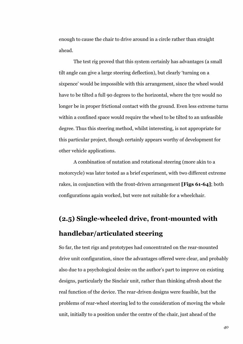
40
enough to cause the chair to drive around in a circle rather than straight
ahead.
The test rig proved that this system certainly has advantages (a small
tilt angle can give a large steering deflection), but clearly ‘turning on a
sixpence’ would be impossible with this arrangement, since the wheel would
have to be tilted a full 90 degrees to the horizontal, where the tyre would no
longer be in proper frictional contact with the ground. Even less extreme turns
within a confined space would require the wheel to be tilted to an unfeasible
degree. Thus this steering method, whilst interesting, is not appropriate for
this particular project, though certainly appears worthy of development for
other vehicle applications.
A combination of nutation and rotational steering (more akin to a
motorcycle) was later tested as a brief experiment, with two different extreme
rakes, in conjunction with the front-driven arrangement [Figs 61-64]; both
configurations again worked, but were not suitable for a wheelchair.
(2.5) Single-wheeled drive, front-mounted with
handlebar/articulated steering
So far, the test rigs and prototypes had concentrated on the rear-mounted
drive unit configuration, since the advantages offered were clear, and probably
also due to a psychological desire on the author’s part to improve on existing
designs, particularly the Sinclair unit, rather than thinking afresh about the
real function of the device. The rear-driven designs were feasible, but the
problems of rear-wheel steering led to the consideration of moving the whole
unit, initially to a position under the centre of the chair, just ahead of the
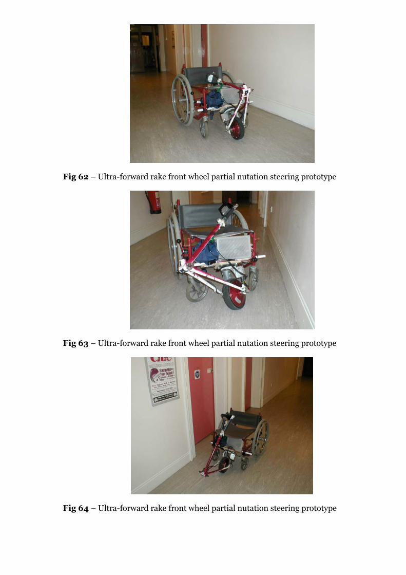
Fig 62 – Ultra-forward rake front wheel partial nutation steering prototype
Fig 63 – Ultra-forward rake front wheel partial nutation steering prototype
Fig 64 – Ultra-forward rake front wheel partial nutation steering prototype

41
centre-line of the rear wheels. This would still give a turning moment for
steering about the point of contact of the rear tyres, and due to the way the
folding structure of the 8L/9L is arranged under the chair, there is a space in
the centre for a wheel the size of the XTi hub motor, together with the forks
and castor bearing. Being this far out of the way under the chair would,
however, make it very difficult to fit and detach, and would require either
powered steering or some kind of linkage or rod system to provide manual
steering, routed through the frame to the user’s hands, which sounded
unnecessarily complex. The simplest solution appeared to be to move the
drive unit to the front of the chair, and use a conventional handlebar
arrangement to steer it manually.
The most distinctive existing products using such an arrangement are
the PDQ Powertrike and the Team Hybrid products; these are very much
higher speed, more powerful devices (intended more for road use) than the
wheelchair drives with which the current project will be compared. They
retain a ‘motorcycle’ metaphor, even though they are front-wheel drive, with
rugged styling and large wheels and do not permit the kind of compact
mobility intended for the new wheelchair drive. It was thus considered that
the powered wheel could be brought closer to the chair – perhaps even under
the footrests, or in between them. The Roll-Aid and Casali designs (see
Product Matrix) both use very small wheels positioned in the space just
behind the footrests, with a straight steering column coming up between the
user’s knees to a set of conventional handlebars in the Roll-Aid’s case, and a
cranked tiller on the Casali unit. The problem of a user gaining access to the
chair is addressed by either folding the handlebars down (Roll-Aid) or tilting
the whole assembly (Casali). It was felt that neither was a good solution, since
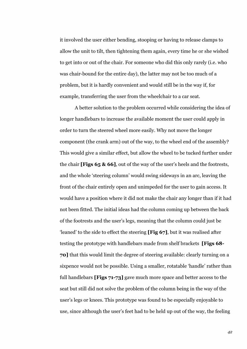
42
it involved the user either bending, stooping or having to release clamps to
allow the unit to tilt, then tightening them again, every time he or she wished
to get into or out of the chair. For someone who did this only rarely (i.e. who
was chair-bound for the entire day), the latter may not be too much of a
problem, but it is hardly convenient and would still be in the way if, for
example, transferring the user from the wheelchair to a car seat.
A better solution to the problem occurred while considering the idea of
longer handlebars to increase the available moment the user could apply in
order to turn the steered wheel more easily. Why not move the longer
component (the crank arm) out of the way, to the wheel end of the assembly?
This would give a similar effect, but allow the wheel to be tucked further under
the chair [Figs 65 & 66], out of the way of the user’s heels and the footrests,
and the whole ‘steering column’ would swing sideways in an arc, leaving the
front of the chair entirely open and unimpeded for the user to gain access. It
would have a position where it did not make the chair any longer than if it had
not been fitted. The initial ideas had the column coming up between the back
of the footrests and the user’s legs, meaning that the column could just be
‘leaned’ to the side to effect the steering [Fig 67], but it was realised after
testing the prototype with handlebars made from shelf brackets [Figs 68-
70] that this would limit the degree of steering available: clearly turning on a
sixpence would not be possible. Using a smaller, rotatable ‘handle’ rather than
full handlebars [Figs 71-73] gave much more space and better access to the
seat but still did not solve the problem of the column being in the way of the
user’s legs or knees. This prototype was found to be especially enjoyable to
use, since although the user’s feet had to be held up out of the way, the feeling
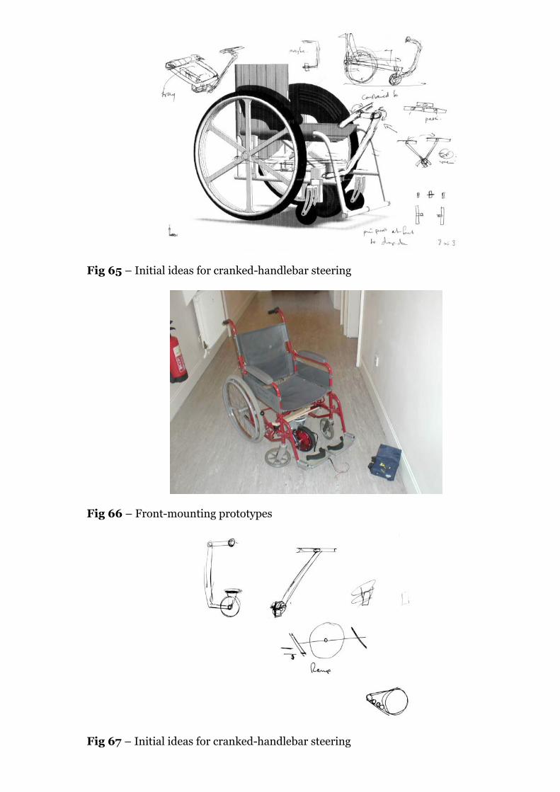
Fig 65 – Initial ideas for cranked-handlebar steering
Fig 66 – Front-mounting prototypes
Fig 67 – Initial ideas for cranked-handlebar steering

Fig 68 – Front-mounting prototypes
Fig 69 – Front-mounting prototypes
Fig 70 – Front-mounting prototypes
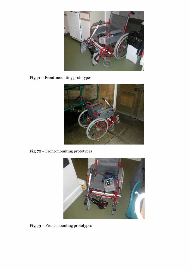
Fig 71 – Front-mounting prototypes
Fig 72 – Front-mounting prototypes
Fig 73 – Front-mounting prototypes

43
of tilting the column to the side gave the impression that this was a very
different type of vehicle – very different to any other electric wheelchair.
The design was thus refined to have the whole steering assembly swing
under the footrests, completely out of the way of the user’s legs [Fig 74]. This
permitted what may be the most interesting feature of the entire project to be
incorporated – the articulated steering. As originally envisaged [Figs 75-78],
the user’s hand grip would be shaped rather like a computer mouse, and held
and moved similarly, in a small arc but remaining parallel to the centre-line of
the chair, with a rotatable linkage to the top end of the steering column
transmitting this shallow arc (hence very little twisting of the user’s spine,
something unavoidable with ‘normal’ handlebars) into full 90 degree
movement of the driving wheel in both directions. Positioning the controls on
this ‘mouse’ (perhaps even in an imitation of the standard mouse layout?)
would bring together all the controls in a simple, one-handed operation.
A prototype was built using the rear frame (45 degrees) from the
Raleigh Equipe [Figs 79-82], with, initially, a simple yoke-shaped hand-grip,
and the controls kept separate from this initially for simplicity. This prototype
demonstrated very neatly the way that no twisting of the user’s spine would be
required in order to steer – pictures show that the hand-grip can remain
entirely parallel with the user’s body as it is swung from side to side, and with
the angled steering column routed under and outside the footrests, full 90
degree steering in either direction was possible. The controls were then added
to the handgrip [Figs 83-87] and this made full one-handed operation
extremely easy. To increase the rigidity of the structure on the frame, a crude
extra light tubular steel arm was added on one side (initially referred to by the
author as a Panhard rod, but the term properly refers to a similar rod intended

Fig 74 – Front-mounting prototypes
Fig 75 – Steering concept
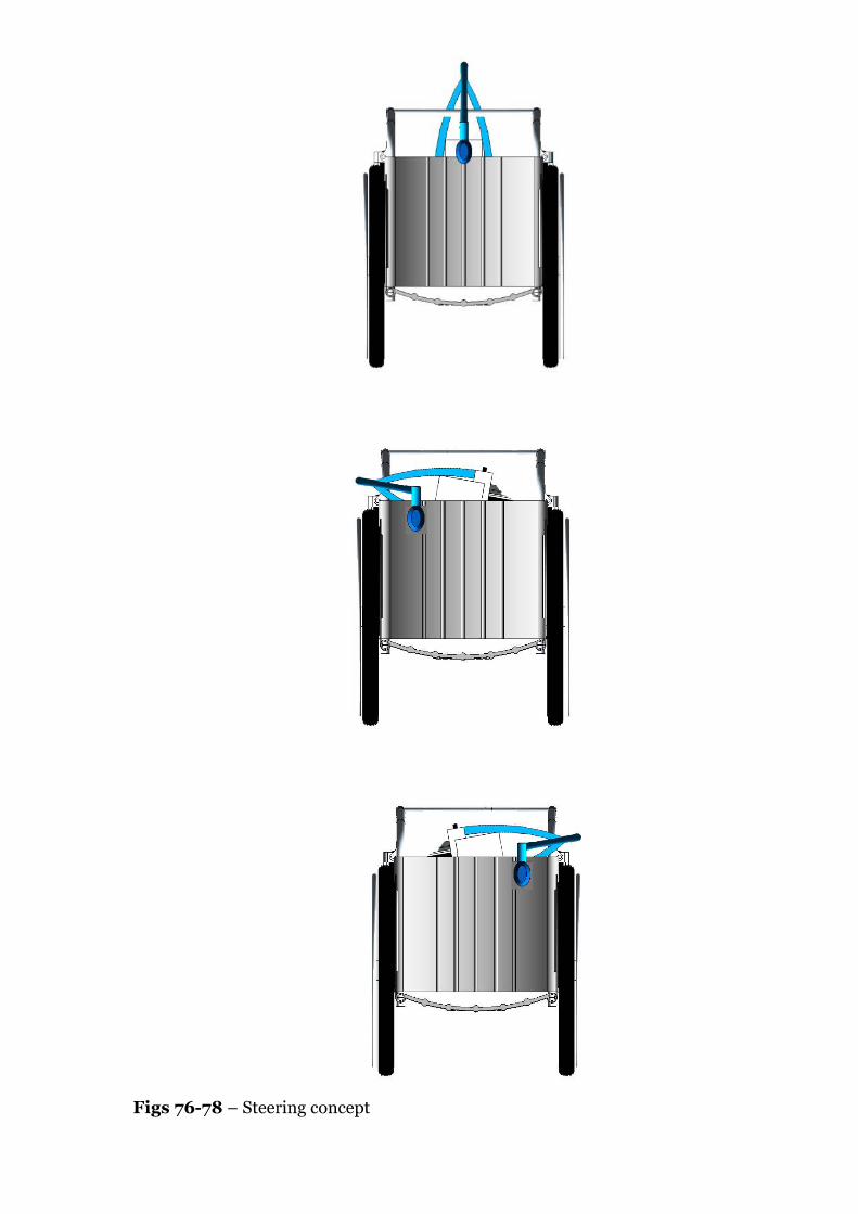
Figs 76-78 – Steering concept
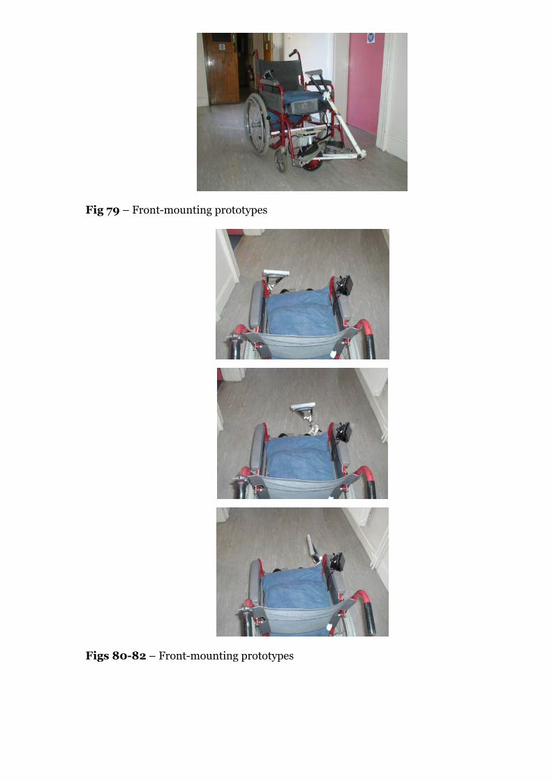
Fig 79 – Front-mounting prototypes
Figs 80-82 – Front-mounting prototypes
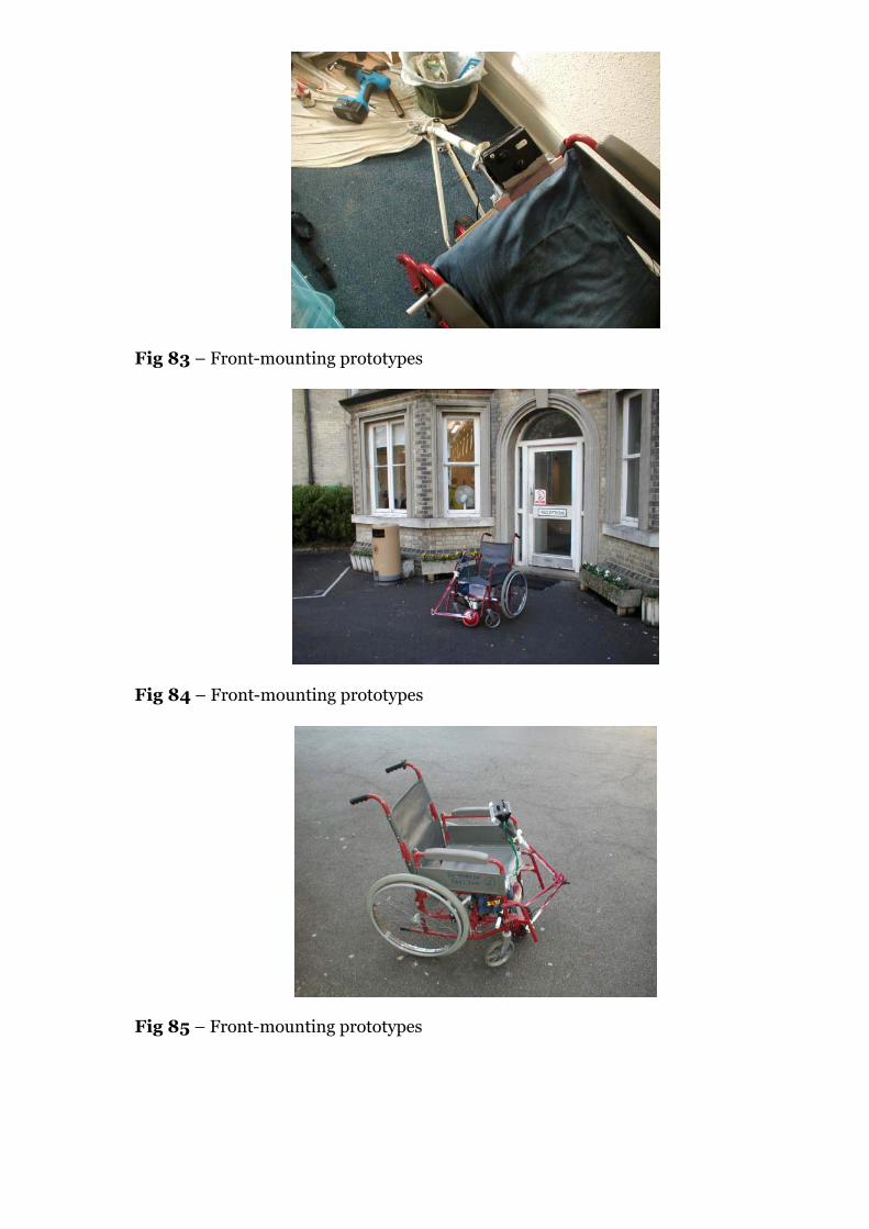
Fig 83 – Front-mounting prototypes
Fig 84 – Front-mounting prototypes
Fig 85 – Front-mounting prototypes

Fig 86 – Front-mounting prototypes
Fig 87 – Front-mounting prototypes
Fig 88 – Front-mounting prototypes
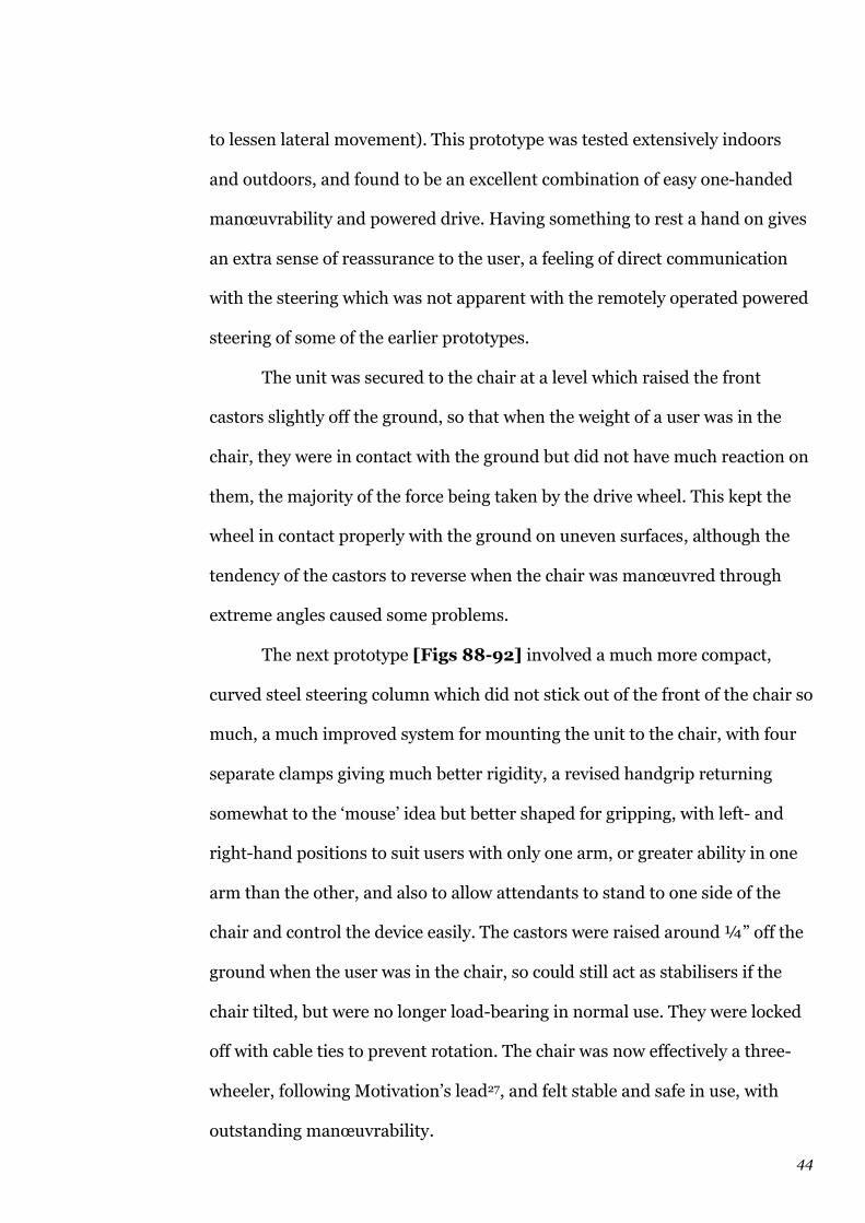
44
to lessen lateral movement). This prototype was tested extensively indoors
and outdoors, and found to be an excellent combination of easy one-handed
manœuvrability and powered drive. Having something to rest a hand on gives
an extra sense of reassurance to the user, a feeling of direct communication
with the steering which was not apparent with the remotely operated powered
steering of some of the earlier prototypes.
The unit was secured to the chair at a level which raised the front
castors slightly off the ground, so that when the weight of a user was in the
chair, they were in contact with the ground but did not have much reaction on
them, the majority of the force being taken by the drive wheel. This kept the
wheel in contact properly with the ground on uneven surfaces, although the
tendency of the castors to reverse when the chair was manœuvred through
extreme angles caused some problems.
The next prototype [Figs 88-92] involved a much more compact,
curved steel steering column which did not stick out of the front of the chair so
much, a much improved system for mounting the unit to the chair, with four
separate clamps giving much better rigidity, a revised handgrip returning
somewhat to the ‘mouse’ idea but better shaped for gripping, with left- and
right-hand positions to suit users with only one arm, or greater ability in one
arm than the other, and also to allow attendants to stand to one side of the
chair and control the device easily. The castors were raised around ¼” off the
ground when the user was in the chair, so could still act as stabilisers if the
chair tilted, but were no longer load-bearing in normal use. They were locked
off with cable ties to prevent rotation. The chair was now effectively a three-
wheeler, following Motivation’s lead27, and felt stable and safe in use, with
outstanding manœuvrability.
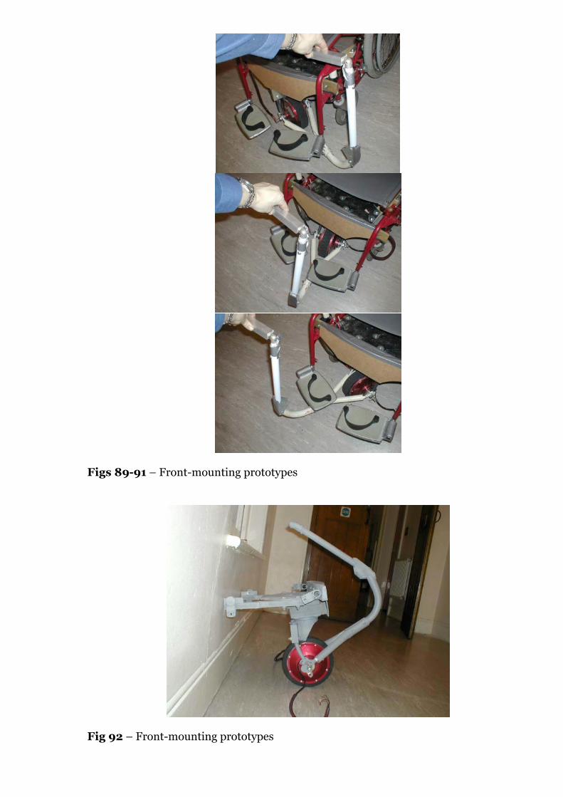
Figs 89-91 – Front-mounting prototypes
Fig 92 – Front-mounting prototypes
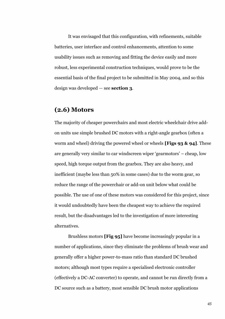
45
It was envisaged that this configuration, with refinements, suitable
batteries, user interface and control enhancements, attention to some
usability issues such as removing and fitting the device easily and more
robust, less experimental construction techniques, would prove to be the
essential basis of the final project to be submitted in May 2004, and so this
design was developed — see section 3.
(2.6) Motors
The majority of cheaper powerchairs and most electric wheelchair drive add-
on units use simple brushed DC motors with a right-angle gearbox (often a
worm and wheel) driving the powered wheel or wheels [Figs 93 & 94]. These
are generally very similar to car windscreen wiper ‘gearmotors’ – cheap, low
speed, high torque output from the gearbox. They are also heavy, and
inefficient (maybe less than 50% in some cases) due to the worm gear, so
reduce the range of the powerchair or add-on unit below what could be
possible. The use of one of these motors was considered for this project, since
it would undoubtedly have been the cheapest way to achieve the required
result, but the disadvantages led to the investigation of more interesting
alternatives.
Brushless motors [Fig 95] have become increasingly popular in a
number of applications, since they eliminate the problems of brush wear and
generally offer a higher power-to-mass ratio than standard DC brushed
motors; although most types require a specialised electronic controller
(effectively a DC-AC converter) to operate, and cannot be run directly from a
DC source such as a battery, most sensible DC brush motor applications
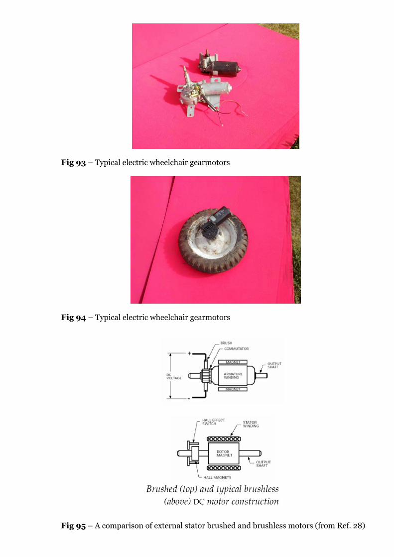
Fig 93 – Typical electric wheelchair gearmotors
Fig 94 – Typical electric wheelchair gearmotors
Fig 95 – A comparison of external stator brushed and brushless motors (from Ref. 28)
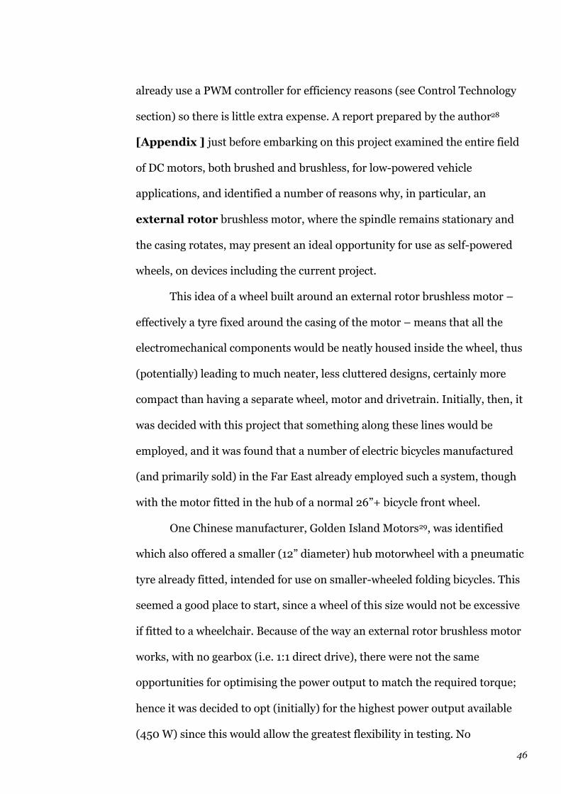
46
already use a PWM controller for efficiency reasons (see Control Technology
section) so there is little extra expense. A report prepared by the author28
[Appendix ] just before embarking on this project examined the entire field
of DC motors, both brushed and brushless, for low-powered vehicle
applications, and identified a number of reasons why, in particular, an
external rotor brushless motor, where the spindle remains stationary and
the casing rotates, may present an ideal opportunity for use as self-powered
wheels, on devices including the current project.
This idea of a wheel built around an external rotor brushless motor –
effectively a tyre fixed around the casing of the motor – means that all the
electromechanical components would be neatly housed inside the wheel, thus
(potentially) leading to much neater, less cluttered designs, certainly more
compact than having a separate wheel, motor and drivetrain. Initially, then, it
was decided with this project that something along these lines would be
employed, and it was found that a number of electric bicycles manufactured
(and primarily sold) in the Far East already employed such a system, though
with the motor fitted in the hub of a normal 26”+ bicycle front wheel.
One Chinese manufacturer, Golden Island Motors29, was identified
which also offered a smaller (12” diameter) hub motorwheel with a pneumatic
tyre already fitted, intended for use on smaller-wheeled folding bicycles. This
seemed a good place to start, since a wheel of this size would not be excessive
if fitted to a wheelchair. Because of the way an external rotor brushless motor
works, with no gearbox (i.e. 1:1 direct drive), there were not the same
opportunities for optimising the power output to match the required torque;
hence it was decided to opt (initially) for the highest power output available
(450 W) since this would allow the greatest flexibility in testing. No

47
torque/speed curves were available on Golden Island Motors’ website, and it
was only after the motor had been purchased and after repeated requests that
some data were put up on the site.
The motorwheel purchased was a Golden Island JD-HSB-36 [Fig 96 &
Appendix] and came with the controller and twist-grip speed control. Before
building it into a wheelchair drive prototype, the author and his brother, Tom
Lockton, tested it extensively on a BMX-style small-wheeled bicycle to become
acquainted with its characteristics [Figs 97 & 98]. The results were pleasing,
at least from the viewpoint of cycling applications: the motorwheel was able to
pull the bicycle (with 12-stone rider) away from standstill with relative ease,
and with a little pedalling help, could easily accelerate the bicycle up to around
12-15 mph on the level. Clearly this was too fast for the wheelchair application
(see Legislation section) but proved the capabilities of the motorwheel unit.
However, it had more difficulty starting the bicycle from rest on anything
more than a very gentle gradient if no pedal assistance were given. To pull
away up a ramp or incline was only possible if the batteries (3 × 12 V lead-
acid, connected in series) were fully charged, otherwise the motorwheel
stalled, i.e. the required torque could not be provided. When the torque/speed
data were made available on Golden Island’s website, it was found that the
maximum torque was 13 lbf ft (18 N m); after a mathematical analysis of what
might be required for the wheelchair drive, it was realised that at least 15.5 lbf
ft (21 N m) was needed (see Mechanics section). For a wheelchair drive
intended to help users drive up ramps and slopes, the Golden Island motor
was not ideal, though some of the features included such as electromagnetic
braking, were potentially very useful. Because no instructions on wiring up
this function were provided by Golden Island, the author, with the kind help
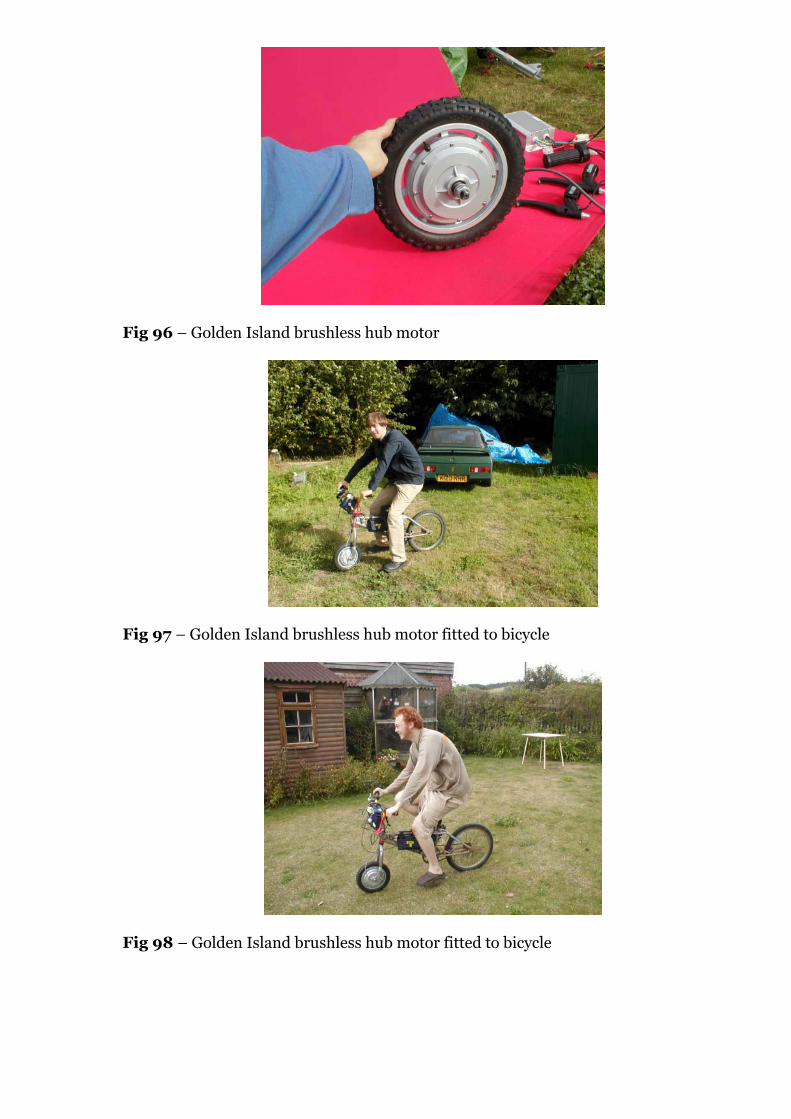
Fig 96 – Golden Island brushless hub motor
Fig 97 – Golden Island brushless hub motor fitted to bicycle
Fig 98 – Golden Island brushless hub motor fitted to bicycle

48
of Phil Wilmore and Richard Thomas, set up a test rig in Kimberley using an
oscilloscope [Fig 99] to determine how to operate this function.
The initial approach of empirical testing, ‘getting stuck in’ rather than
reasoned mathematical planning is easy to criticise, but it allowed the project
to move ahead in many ways before the serious business of tying down the
mechanical specification became necessary (this is covered in detail in the
Mechanics section below).
Hence, although it was recognised that the JD-HSB-36 did not have a
sufficient torque output to be completely suitable for the intended application,
it was decided to proceed with using it in the initial prototypes, since it offered
some dimensions and capabilities around which to work. Thus first prototypes
were built [Fig 100] incorporating the motor without any steering function,
to determine geometry requirements, and these then progressed to manual
steering prototypes in different configurations as described in detail earlier in
the Development section.
After a full mathematical analysis of the motor requirements (see
Mechanics section), the conclusion was reached that either the existing
Golden Island JD-HSB-36 needed to have its torque output increased, or a
different motor or drive system needed to be investigated. Without any
gearbox, and with no easy way of incorporating one, an external rotor
brushless motor such as the Golden Island unit cannot have its torque/speed
ratio changed except through adjustment of the AC output provided to the
coils by the controller. A comment from engineer Mr Dmitriy Yavid, engaged
on a project to produce a motorised tricycle, and who had read the details of
the wheelchair drive project on the website (see User Consultation section),
ran as follows:

Fig 99 – Golden Island brushless hub motor
Fig 100 – Golden Island brushless hub motor fitted to chair (non-steering)
Fig 101 – XTi motor

49
“As to increasing the torque of a brushless motor electronically, it’s
possible, but not by much. A bi-polar sinewave drive would give you perhaps
20...30% extra, for the cost of much more complex electronics.” 30
This method was considered, and details of how to achieve this were
researched, and discussed with Dr Harrison, but having seen that even the
hypothetical 30% increase in torque, assuming it could be achieved, would
only provide 17 lbf ft (23 N m), and 15.5 lbf ft (21 N m) was estimated to be the
absolute minimum needed (see Mechanics section). Thus it was decided to
find an alternative motor and/or drive method, with higher torque output,
ideally still in a conveniently compact package.
Other brushless hub motors were investigated [Appendix ], following
suggestions from wheelchair users and interested visitors to the website (see
User Consultation section). Although some (e.g. Emoteq’s Megaflux range and
Heinzmann’s wide range of products) offered much higher torque than the
Golden Island units, due to the use of rare earth magnets, the prices were
prohibitive.
A more promising route forward was discovered through idly
investigating some parallel products to wheelchair drives – powered add-on
units for propelling shopping trolleys, golf bags, etc. A company based in
Arkansas, Assembled Products Corporation31, offers the Cart Pusher, a
powered drive unit designed to push up to twenty shopping trolleys at a time,
and the Mart Cart, a kind of heavy-duty mobility scooter apparently intended
for more obese supermarket customers who find it difficult to walk, with
extra-wide seat, large shopping basket and storage area, etc. Both products
use a low-speed, high-torque hub motor of APC’s own design and
construction, the XTi (“Extreme Technology and Innovation”) which
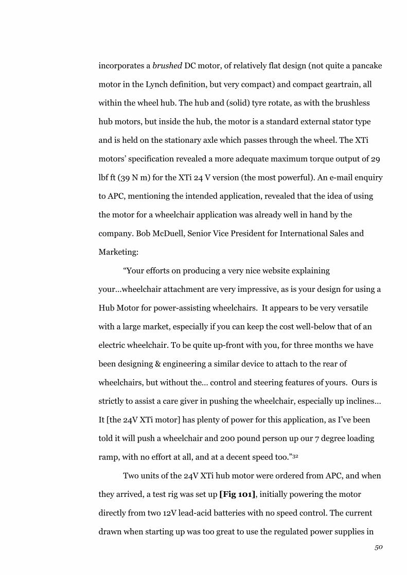
50
incorporates a brushed DC motor, of relatively flat design (not quite a pancake
motor in the Lynch definition, but very compact) and compact geartrain, all
within the wheel hub. The hub and (solid) tyre rotate, as with the brushless
hub motors, but inside the hub, the motor is a standard external stator type
and is held on the stationary axle which passes through the wheel. The XTi
motors’ specification revealed a more adequate maximum torque output of 29
lbf ft (39 N m) for the XTi 24 V version (the most powerful). An e-mail enquiry
to APC, mentioning the intended application, revealed that the idea of using
the motor for a wheelchair application was already well in hand by the
company. Bob McDuell, Senior Vice President for International Sales and
Marketing:
“Your efforts on producing a very nice website explaining
your…wheelchair attachment are very impressive, as is your design for using a
Hub Motor for power-assisting wheelchairs. It appears to be very versatile
with a large market, especially if you can keep the cost well-below that of an
electric wheelchair. To be quite up-front with you, for three months we have
been designing & engineering a similar device to attach to the rear of
wheelchairs, but without the… control and steering features of yours. Ours is
strictly to assist a care giver in pushing the wheelchair, especially up inclines…
It [the 24V XTi motor] has plenty of power for this application, as I’ve been
told it will push a wheelchair and 200 pound person up our 7 degree loading
ramp, with no effort at all, and at a decent speed too.”32
Two units of the 24V XTi hub motor were ordered from APC, and when
they arrived, a test rig was set up [Fig 101], initially powering the motor
directly from two 12V lead-acid batteries with no speed control. The current
drawn when starting up was too great to use the regulated power supplies in

51
Kimberley. A neat feature of the XTi motors is a mechanical parking brake,
operated by turning a T-piece on one end of the axle.
At this stage, a new prototype was built around the new motor, but it
was apparent that a proper PWM controller would be needed to make best use of
it, so this became another strand of development (see Control Technology
section). The XTi motor proved excellent, extremely capable in prototype
testing, and was thus retained for use in the final design.
(2.7) Mechanics
There are two strands to the mathematical analysis needed in this project –
the motor/drive requirements (torque, speed) and the structural requirements
(material choice, frame design). To some extent, the structural requirements
were more difficult to pin down at any stage, since the purpose of the
prototypes was mainly to investigate, empirically, a variety of different
structures and layouts. Thus the motor/drive requirements were the easiest to
analyse, though by no means as definitive as might have been desired.
First, the maximum speed under power of the powered chair must not
exceed 4 mph (see Legal Requirements section). Assuming, for simplicity,
that there is at least some onus on the user to brake or control the speed
sensibly so that the chair does not exceed 4 mph if travelling downhill, it can
be said that the motor/drive/wheel combination must provide a
road/pavement speed of 4 mph on the level.
In terms of considering the real need for the project, however, it is clear
that the focus of the calculations needs to be on powering the chair up
gradients, since maintaining a speed of 4 mph on the level would not be
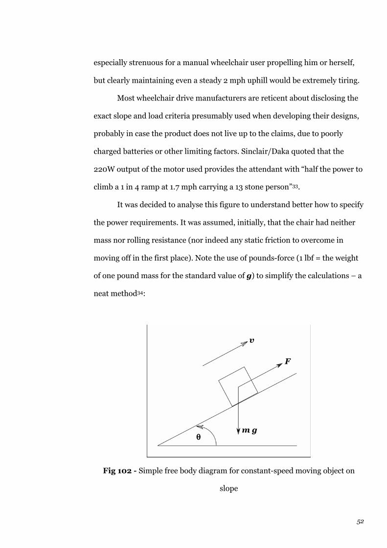
52
especially strenuous for a manual wheelchair user propelling him or herself,
but clearly maintaining even a steady 2 mph uphill would be extremely tiring.
Most wheelchair drive manufacturers are reticent about disclosing the
exact slope and load criteria presumably used when developing their designs,
probably in case the product does not live up to the claims, due to poorly
charged batteries or other limiting factors. Sinclair/Daka quoted that the
220W output of the motor used provides the attendant with “half the power to
climb a 1 in 4 ramp at 1.7 mph carrying a 13 stone person”33.
It was decided to analyse this figure to understand better how to specify
the power requirements. It was assumed, initially, that the chair had neither
mass nor rolling resistance (nor indeed any static friction to overcome in
moving off in the first place). Note the use of pounds-force (1 lbf = the weight
of one pound mass for the standard value of g) to simplify the calculations – a
neat method34:
Fig 102 - Simple free body diagram for constant-speed moving object on
slope

53
Power = P
Road speed = v
Tractive effort = F
Mass of user = m
Angle of slope = q
(the use of ‘1 in x’ values for slopes is assumed in this case to be the more
common tangent-based notation, i.e. 1 in 4 = arctan ¼, rather than the sine-
based railway gradient system where 1 in 4 = arcsin ¼)
v is constant
forces on object are in equilibrium
tractive effort F = total resistive forces on object
Resistive force on object is made up (in this simple case) of component of
object’s weight acting down the slope in the same line as the tractive effort;
F = mg sin q
Using P = F v:
P = v mg sin q
With mg = 13 stone-force = 182 lbf, v = 1.7 mph = 2.49 ft s-1 and q =
arctan ¼ = 0.245 rad = 14 degrees:
P = 2.49 × 182 × sin 0.245 = 110 lbf ft s-1 = 0.2 hp

54
With 1 hp = 745.7 W:
P = 149 W
This analysis indicates that the weight and rolling resistance of the chair itself
must be an extremely significant part of the equation when designing
wheelchair drives, since if 220 W is “half the power required” then 440W is
the actual power – significantly greater than the 149 W predicted by the
simple analysis. There are some possible adjustments to the 220W figure –
this was quoted to Daka by the motor manufacturer and it may be assumed
that this was the power input to the motor, i.e. volts × amps. The motors were
very cheap 550 series brush motors, probably no greater than 80% efficiency;
the gearbox was in turn probably not even 70% efficient in normal use, since it
was loosely constructed in the casing with a lot of backlash. This brings the
220 W potential maximum output down to 12o W at the road wheel.
A more realistic analysis was undertaken after testing the Red Cross 8L
chair to determine rough values for rolling resistance and static friction in the
wheel bearings, etc. These values were measured as simply as possible by
setting the chair on the level, on a smooth linoleum floor, with the armrests
and footrests in place, the front castors set to the correct (trailing) position,
and pulling it forwards using a spring balance hooked around part of the
frame until it just started to move (the maximum force value reached by the
balance was taken as one value for the maximum static frictional resistance)
and the force on the balance reached a constant value as the chair was pulled
at a constant speed (walking pace). This was necessarily an extremely rough
55
measurement, but revealed values of around 0.25 kgf (~ 2.5 N or 0.55 lbf) for
the maximum static frictional resistance and 0.15 kgf (~1.5 N or 0.33 lbf) for
the constant rolling resistance at a normal walking pace (around 4 mph).
Of course, these values will vary a great deal for different chairs, in
different conditions. The 8L acquired by the author for this project was in
poor condition; the wheel bearings feel worn and the tyres are not only
perishing but at the time of the rolling resistance test were left in exactly the
slightly underinflated state they were in when the chair was acquired from the
Red Cross – i.e., the chair may well be representative of many thousands in
use in the UK and abroad, particularly by hospitals and charities35.
The mass of the standard 8L, according to Remploy36, is 40 lb (18.5 kg)
including armrests and footrests. Using this information, an additional test
was carried out to determine the maximum static frictional force, by placing
the chair on a flat, rigid board, and inclining the board until the chair just
started to roll forwards. The angle at which this occurred was (very
approximately) 2 degrees, i.e. 1 in 45 using the arctan system. This means that
the effective maximum coefficient of static friction mmax = 0.02 for the wheel
bearings in this situation, but it is more useful to know the actual force that
would be required to overcome the friction; the easiest example is on the level:
Weight of empty chair = 40 lbf = normal reaction R
Maximum coefficient of static friction in bearings mmax = 0.02
Using F = mmax R:
F = 0.02 × 40 = 0.8 lbf (0.36 kgf, or 3.6 N)
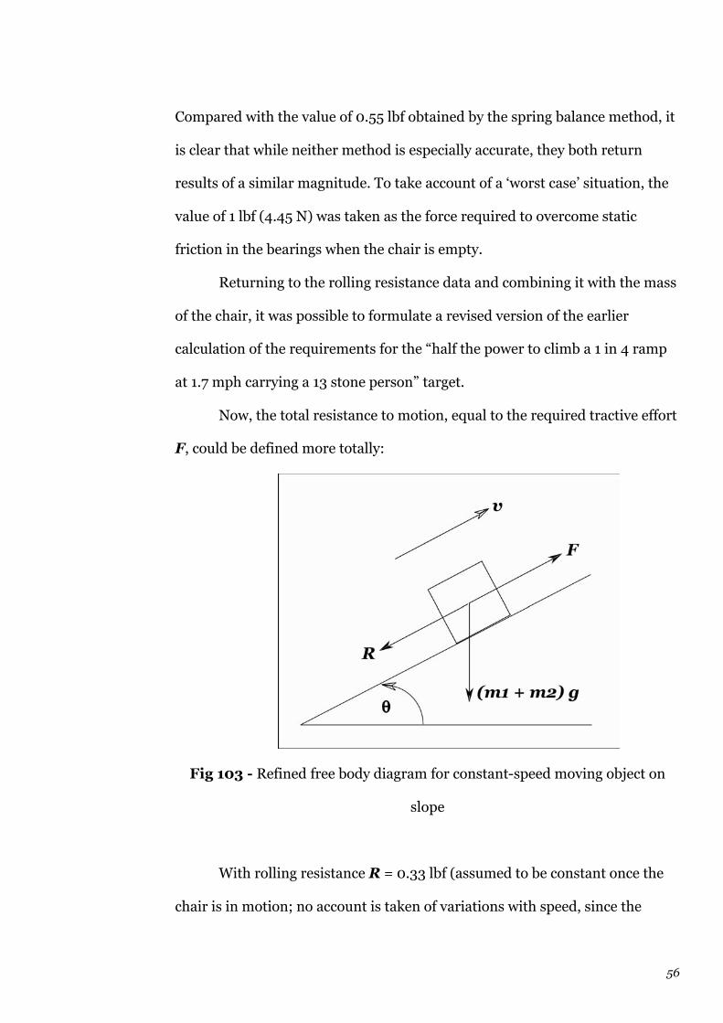
56
Compared with the value of 0.55 lbf obtained by the spring balance method, it
is clear that while neither method is especially accurate, they both return
results of a similar magnitude. To take account of a ‘worst case’ situation, the
value of 1 lbf (4.45 N) was taken as the force required to overcome static
friction in the bearings when the chair is empty.
Returning to the rolling resistance data and combining it with the mass
of the chair, it was possible to formulate a revised version of the earlier
calculation of the requirements for the “half the power to climb a 1 in 4 ramp
at 1.7 mph carrying a 13 stone person” target.
Now, the total resistance to motion, equal to the required tractive effort
F, could be defined more totally:
Fig 103 - Refined free body diagram for constant-speed moving object on
slope
With rolling resistance R = 0.33 lbf (assumed to be constant once the
chair is in motion; no account is taken of variations with speed, since the

57
speeds involved are so low), the mass of the user m1 = 182 lb and the chair m2
= 40 lb:
F = R + [(m1 + m2) g] sin q
= 0.33 + (182 + 40) sin 0.245
= 54.18 lbf
P = F v = 54.18 × 2.49 = 139.4 lbf ft s-1 = 0.245 hp = 183 W
What about the initial force required, to overcome the static friction?
This will be the same equation, but with the value of 1 lbf replacing the 0.33
lbf rolling resistance, hence a force of 54.85 lbf – not significantly different.
The power required in this case will be delivered by an initial high current
drain, to accelerate the chair and occupant to the required speed. Since v = 0
at the instant of starting off, this cannot be used for the power calculation, so
in a ‘worst case’ situation, it would be F = 54.85 lbf together with v = 2.49 ft s-
1, to give P = 185 W.
Assuming that the wheelchair drive under development will need to
provide all the power needed to propel the user and chair up a slope (when
used in attendant mode, the attendant could push a little, but it is desirable
that he or she does not have to do so), a power output of 180-200 W at the
wheel appeared to be most suitable.
It was considered, though, that the 1 in 4 slope was probably beyond
what most users would need to negotiate. The very steepest parts of Porlock
Hill in Somerset are only 1 in 4, and whilst the Hardknott Pass in the Lake
District reaches 1 in 3 at one point, the average wheelchair user is unlikely to

58
need this ability in everyday life. The steepest wheelchair ramps are usually
those going into a van or minibus, and these are rarely steeper than 1 in 7. This
seemed a more realistic target. Other refinements to the earlier target include
raising the user’s weight to 15 stone (210 lb) rather than 13, since although
according to the DTi’s Adultdata37, the UK mean is only 79.75 kg (12 stone 10
lb) for males and 66.7 kg (10 stone 7 lb) for females, the trend is towards
increasing weight so that within a decade, the mean is likely to have increased.
The Adultdata figures are based on lightweight, indoor clothing and no shoes,
so some provision needs to be made for full outdoor clothes, which may
include a thick overcoat or blanket for a wheelchair user. There is probably
greater variation in weights amongst wheelchair users than the population as
a whole, since for some, the relative lack of exercise can lead to obesity, whilst
for others, a wasting disease can lead the person to become seriously
underweight.
One point which is missed by the Sinclair target figures is that one of
the reasons people may be out in a wheelchair in the first place is to go
shopping, or to and from work, for example. This means they are likely to
need to carry shopping bags or other bags of some kind; where on the chair
they are stored may be outside the scope of this project, but it is clear that the
weight of the person plus baggage will be a greater figure than the assumed 13
stone.
So the new target figures decided upon for the project, based on this
discussion, were specified as:
100% of the power required to propel a standard 8L wheelchair, with
a total load of 15 stone (user plus bags, etc), at 2 mph constant speed, up a 1
in 7 slope.
59
The 2 mph (2.93 ft s-1) figure, as well as being more convenient to
quote, also compensates somewhat for the reduction in intended slope angle,
and probably comes closer to normal walking pace up that level of slope.
Hence:
P = v × [R + ([m1 + m2] g) sin q]
= 2.93 × (0.33 + 250 sin (arctan 1/7))
= 104.6 lbf ft s-1 = 0.19 hp = 142 W
Giving the user some reserve of power above this point, for the occasional
severe ramp or steeply lowered kerb (or run-down battery) means that the
target of 180-200 W at the wheel still made sense, and was proceeded with.
As was seen with the Golden Island brushless, gearless motor, however,
even a nominal output of 450W is not appropriate if the output cannot deliver
the torque needed. In terms of the specification just advanced:
With P = 180 W, v = 2.93 ft s-1 and a wheel diameter of 8¼” including
the tyre (XTi motor), circumference = p × 8¼” = 25.905” = 2.16 ft:
w = 2.93 / 2.16 = 1.36 Hz = 8.54 rad s-1 = 81.6 rpm
Using P = T w, T = P / w
T = 180 / 8.54 = 21 N m = 15.5 lbf ft
So the required torque to be provided by the motor to fulfil the
specification is greater than the absolute maximum offered by the Golden
Island motor. Perusal of the APC XTi motor’s torque-speed curves and data,

60
however [Fig 104] reveals that at the 81.6 rpm level, the torque would be
around 20 lbf ft – thus more than sufficient for the application. The XTi motor
with its integral gearbox is ideally suited to this application.
No attempt was made to produce more than a crude idea of the load-
speed characteristics for the wheelchair drive, since the focus had been on the
specific case of a gradient situation. In terms of the stall torque on a gradient
– the ability to set off driving up the slope – using the total mg sin q
component down the 1 in 7 slope, plus the static frictional force of 1 lbf, gives
36.5 lbf force down the slope; at a wheel radius of around 4” = 0.33 ft for the
XTi motor, the stall torque is only around 12 lbf ft – well within the XTi’s
capability.
In terms of structural mechanics, although initially, attempts were
made to analyse the forces acting on the chair at various times [Fig 105], the
development of the structural requirements was left mainly to empirical
methods: building the prototype, finding it flexed too much, then stiffening it
until it didn’t. Later, FEA was used to a limited extent to analyse a particular
part of the attachment mechanism (see section on Development of subframe).
(2.8) Control technology
The Golden Island brushless controller, dealt with in the Motors section, did
not need to be examined in detail for this project, even at the stage when the
brushless motor was being used. The technology was not easily modifiable and
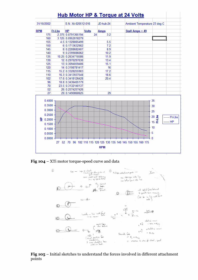
Fig 104 – XTi motor torque-speed curve and data
Fig 105 – Initial sketches to understand the forces involved in different attachment points

61
as the project progressed, a much more suitable motor was found which did
not require a brushless controller.
As mentioned earlier, the benefits of using a pulse-width modulated
‘chopper’ controller to vary the speed of a DC motor such as the XTi units
outweigh the extra complexity (and cost) over a simple variable resistor speed
control, certainly for a relatively high current drain application such as the
wheelchair drive.
A standard DC permanent magnet motor’s speed is proportional to the
applied voltage (Faraday’s Law); hence the higher the voltage applied, the
faster the motor will turn. The motor’s current-speed draw characteristic is
generally similar to the torque-speed curve [Fig 104], so at low speeds (e.g.
when the motor is first switched on and accelerates to the speed set by the
applied voltage), the current draw will be especially high, and since power loss
due to resistance heating, P = I2 R, the wasted power is proportional to the
square of the current drawn. To prevent the high current damaging the motor
coils or battery, a method is needed to drop some of the applied voltage during
this phase; a basic potentiometer resistor control, gradually turned to increase
the voltage, works, but wastes a lot of energy in resistance heating38.
A pulse-width modulated controller, on the other hand, produces an AC
waveform in which the mark-space ratio (the proportion of time that the
voltage is ‘on’ compared with the time it is ‘off’) determines the average value
of the voltage, but without the detrimental effects of resistance heating. So to
achieve the same effect of smoothly accelerating a motor from rest to its
maximum speed, which may occur at an applied 24 V, the PWM controller
would apply a (probably square) waveform which saturates at 24V positive,
with a minimum value of 0 V. Initially, the ‘spaces’ would be large, so that the
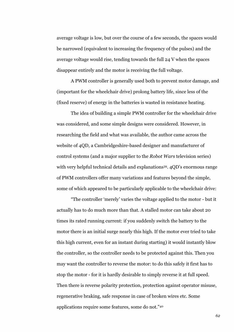
62
average voltage is low, but over the course of a few seconds, the spaces would
be narrowed (equivalent to increasing the frequency of the pulses) and the
average voltage would rise, tending towards the full 24 V when the spaces
disappear entirely and the motor is receiving the full voltage.
A PWM controller is generally used both to prevent motor damage, and
(important for the wheelchair drive) prolong battery life, since less of the
(fixed reserve) of energy in the batteries is wasted in resistance heating.
The idea of building a simple PWM controller for the wheelchair drive
was considered, and some simple designs were considered. However, in
researching the field and what was available, the author came across the
website of 4QD, a Cambridgeshire-based designer and manufacturer of
control systems (and a major supplier to the Robot Wars television series)
with very helpful technical details and explanations39. 4QD’s enormous range
of PWM controllers offer many variations and features beyond the simple,
some of which appeared to be particularly applicable to the wheelchair drive:
“The controller ‘merely’ varies the voltage applied to the motor - but it
actually has to do much more than that. A stalled motor can take about 20
times its rated running current: if you suddenly switch the battery to the
motor there is an initial surge nearly this high. If the motor ever tried to take
this high current, even for an instant during starting) it would instantly blow
the controller, so the controller needs to be protected against this. Then you
may want the controller to reverse the motor: to do this safely it first has to
stop the motor - for it is hardly desirable to simply reverse it at full speed.
Then there is reverse polarity protection, protection against operator misuse,
regenerative braking, safe response in case of broken wires etc. Some
applications require some features, some do not.”40

63
Features which particularly appealed for the intended application were
the clever reversing technique (slowing the motor down before starting it
again in the opposite direction), safety cut-outs, and, especially, the
regenerative braking capability, where the motor can be effectively used as a
generator when the chair is going downhill – the user would set the required
(safe) speed and the motor would act as a braked wheel, with the braking
effect coming from the fact that the energy is being diverted to charge the
batteries through the controller: an ideal solution for maximising battery life
in an application where this really is a crucial issue.
After reviewing the features of a number of different 4QD controllers, it
was decided to purchase the NCC-35-24V Mark 2 controller, which features:
• Overvoltage protection
• Regenerative braking
• Dual ramp reversing
• Half speed reverse (configurable)
• Gain adjustment
• Potentiometer fault protection
• Current limiters for both drive (50 A) and regeneration
From the point of view of this discussion, the important features are items
such as: the half speed reverse (the user is limited to only half the maximum
speed in reverse as in the forward direction), which could prove a very useful
safety feature if a user accidentally operates the chair in reverse in a crowded
or dangerous area; the current limiters, so that if the user drives the chair into
a wall or kerb, for example, and stalls the motor, the controller will cut power

64
to it to prevent damage; potentiometer fault protection, so that if the speed
control is damaged, for example, or fails to operate, the controller will shut the
motor down rather than allow it to speed up dangerously; and the gain
adjustment, which allows the acceleration rate of the motor to be set (i.e. how
quickly the mark-space ratio of the PWM changes) and hence determines how
quick the drive unit is to respond. In this project, the acceleration rate has
been set to very slow, to give safe and predictable behaviour for the user.
4QD’s extremely helpful instruction manual is included in the
Appendix; the unit purchased was a ‘bare board’ to save money, hence many
hours of work were required to set it up ready for use, but once connected to
the controls, batteries and XTi motor, it was soon ready to go, and proved
successful up to a point (but see section 3).
At a stroke, the use of the 4QD controller moved the whole project on
tremendously, and allowed more efforts to be directed into other aspects,
including the actual user interface, since this is clearly one of the most
important aspects in product design terms, if not necessarily from a technical
point of view.
Early in the project, when the idea of an attendant being able to control
the chair from alongside rather than behind was first considered, in
conjunction with fully electronic powered steering, it was thought that a
remote control (even wireless) would be a novel, and useful feature. A small
handset could be held by either the attendant or the user, giving unrivalled
freedom in terms of where the person’s hand could rest or be positioned. It
was envisaged that there would be a very limited range for the handset’s
transmitter, with a requirement that as soon as it went out of range, the
65
wheelchair drive motor would shut down for safety. This would help prevent
accidents due to the user, for example, dropping the handset.
A development of this idea was a remote control ‘glove’ or mitten that
could be worn, again by either the user or an attendant, incorporating the
required controls (at this stage the exact details of what controls would be
needed had not been fully considered). It would be less likely to be dropped,
and if well-designed, the hand could still be positioned wherever it was
comfortable (for some users with weakened or swollen arms, the most
comfortable position may always be ‘the next one’ – i.e. the glove would have
to be robust enough to stand a lot of moving around into different positions).
There was the issue of possible interference (e.g. a child’s radio-
controlled car controller interfering with the wheelchair drive, with dangerous
consequences), but this could be overcome with the use of an encoded
transceiver set, e.g. from Radiometrix. However, the entirely negative
comments received about the idea of a remote (i.e. non-wire linked) control of
any kind, particularly from wheelchair users on various forums (see User
consultation section) led to the idea being retired in favour of a more
conventional fixed control panel or module.
When the powered steering was introduced, along with the 4QD
controller, the business of exactly what controls would be required came to the
fore. The powered steering as implemented on the prototype needed a DPDT
centre-off switch, so that the user had a central position where there was no
power to the steering motor, and the wheel was directed straight ahead, then
left and right positions. The switch used was a 3-position slide control, so that
to steer the chair to the right, the user would slide this switch to the right, and

66
return the switch to the centre to straighten up again. In retrospect, a joystick
sprung to return to the central position would have been superior.
The 4QD controller was connected to have three control inputs – a
rotary potentiometer for speed control, a direction (forward/reverse) rocker
switch, and a master on-off switch (a toggle switch). Together the four
disparate switches did not present a coherent appearance, but
were surprisingly practical, since in normal use the user only needed to
operate the steering – once the speed was set, there was only the steering to
worry about. Because of the way the 4QD controller operates, flicking the
toggle switch to the ‘off’ position effectively brakes the motor as the back EMF
is ‘dumped’ into the batteries, so this was a fine way of braking where needed;
to speed up again to the previous speed, the toggle switch was switched back
to ‘on’ and the motor slowly accelerated to the pre-defined top speed set by the
potentiometer.
In this sense, the idea of the potentiometer being merely a ‘speed
control’ as it would be if there were no PWM controller in between it and the
motor, is too simplistic to describe the way it operates in this situation. It is
actually a desired maximum speed setting, i.e. a ‘cruise control’; the on-off
switch is really the speed controller since it controls whether the wheelchair is
accelerating (switch on) or decelerating (switch off).
Although when the first front-wheel drive prototypes were built, the
control interface (with the exception of the now redundant powered steering
switch) was simply moved to the front (initially to a position on the armrest,
but then, sensibly, to the centre of the steering tiller), the idea of optimising
the controls to make the most of the on-off switch’s clever speed control
capability (in effect, of course, the user is ‘chopping’ the chopper controller’s
67
power supply him or herself!) was considered more fully, and the plan evolved
to use a sprung (momentary action) on-off switch, positioned to be operated
by the user’s index finger, with a sliding potentiometer cruise control mounted
where it can be controlled by the thumb. The forward/reverse switch would be
mounted next to the on-off speed control for operation by the middle finger.
The shape of the control/handgrip is an evolution of the ‘mouse’ idea (see
Development section) but fitted transversely, with two possible positions (left-
handed and right-handed); as can be seen in section 3, the design again
evolved considerably and was not without problems.
(2.9) Usability
This is a broad subject heading, but there are a number of issues with the
project which may be considered to be usability-related. By the January viva,
only some had been fully addressed, and the subsequent development
(section 3) saw the rest investigated, with varying degrees of success:
• Attaching and detaching the drive unit from the chair was relatively
easy using the 4-clamp system for an able-bodied person who can
bend down to reach under the chair, but would be difficult for a user
to do whilst sitting in the chair, and use of Allen keys is hardly ideal
for someone with arthritis or poor hand control. It was envisaged
that large hand-grip wheel clamps were needed, or chunky quick-
release clamps. This needed to be examined carefully, as it is one of
the criteria in the original specification. The 4-clamp system had

68
been built rather than designed. What about an easy way to adjust
the distance between the clamps for fitting to different width chairs?
• How easy is it to propel the chair manually with the drive unit
fitted? What is the rolling resistance of the drive unit wheel
(gearb0x and motor)? Can the regenerative braking feature be
disconnected for manual propulsion? Or would it be better to lift the
drive wheel off the ground, and lower the castors again? How –
spring-loaded, pneumatic, geared?
• Is there anything clever that can be done with helping the drive
wheel up bumpy lowered kerbs and so on – could it lay its own track
or ramp?
• Bumpers/rubbing strips/mudguards to protect the user and the
drive unit?
• How much adjustment will be needed in parts such as the steering
column to cover the anthropometric range?
• Any way of ‘locking’ the drive unit controls, with a key or similar, for
security?
• How to incorporate a control to operate the XTi motor’s integral
parking brake
(2.10) User consultation
The project was discussed with many people from an early stage, and their
comments and ideas were taken into account. Initially positive comments
were received from Anne Barcroft, an occupational therapist (and West
London Institute graduate) at the Red Cross Daily Living Centre in Hove,

69
Sussex, Geoffrey Gane, a director of C. F. Hewerdine Ltd of Thorpe Lea (see
Specification section), and staff at Fremington Manor, a nursing home in
north Devon. All three offered to try out and comment critically on the design
when the prototypes had reached a more advanced stage, and given time
constraints, at least some offers were planned to be taken up.
A discussion41 with David Constantine, an RCA graduate and co-
founder of Motivation (a design-led charity working to improve mobility and
quality of life in developing countries, best known for having developed its
own range of manual wheelchairs) proved very helpful. Mr Constantine, a
wheelchair user himself, was enthusiastic about the project, describing it as:
“Much needed. A power unit such as this is desperately needed”42. He went on
to comment that ideally, for use in developing countries, a petrol engined
drive wheel would be more suitable than an electric motor, due to the
difficulty of charging batteries, but that the idea of a low-cost add-on power
unit was spot-on and Motivation would love to be able to offer something
along these lines which could be easily assembled ‘in the field’ with the
minimum of equipment.
Mr Constantine said that the most important features to consider were
whether the user would have to pay any price for the extra power in terms of
limiting manœuvrability, e.g. would the wheelchair still be able to turn around
in a confined space such as a lift, with the new power attachment in place?
Would the user still be able to climb and descend lowered kerbs properly?
Could the chair still easily be manœuvred manually if the power unit failed?
These were all useful questions to consider, and were taken into account
during the development process.
70
In speaking with Motivation’s Sarah Beattie43, a Brunel Design
graduate, it was suggested that the prototype (once at a more advanced stage)
could be taken to Motivation’s Bristol research and development centre for a
critique by the experienced design team there, headed by another Brunel
Design graduate, Chris Rushman, and it was planned that this would be done
towards the end of the project, but various factors conspired against the event.
In the event, Motivation staff will see the prototype at Good Thinking : Brunel
Design 04 and it is hoped to have a brief critique.
At a very early stage in the project, indeed before much work had been
done, a website44 [Fig 106] was set up, with a guestbook [Appendix ], in
order to start publicising the project and collecting comments from wheelchair
users and other interested parties. The website was developed and extended as
the project progressed and has proved to be a very good way of explaining the
ideas behind the project. For a while it was the top result in search engine
Google for “wheelchair drive” and guestbook entries reveal that most people
have found the site while searching for details of power unit add-ons for
wheelchairs or similar. Some visitors have been engineers and designers
interested in brushless or hub motors, and where possible, replies have been
sent giving help or supplying requested information.
Postings were also made on a range of forums discussing disability and
mobility issues and equipment, with the best results (in terms of replies)
received from the Disabled Living Foundation, Disability Now and Youreable
forums. These comments are included in the Appendix. One recurring
comment was that having a rear-mounted drive wheel would probably be in
the way of an attendant’s feet,; whilst this was not felt to be that much of a
problem as the design progressed, with the wheel tucked well under the back

Fig 106 – The website set up to complement the project
71
of the chair, the fact that a prospective buyer’s perceptions were coloured in
this way, is worth considering. A number of comments were from wheelchair
users offering to test the device.
A visit was made to the British Invention Show at the Barbican in
November 2003, since a year previously at the same event, the author had
seen and tried out the new Trevor Baylis Troll wheelchair drive prototype, and
discussed the design (at this stage an attendant-only device) with Mr Baylis.
At the 2003 show, the Troll was not on show, but a Mr David Jackson, the
device’s designer, working on behalf of the Trevor Baylis Foundation, was
present, and the opportunity was taken to introduce the current project and
discuss the themes involved. Mr Jackson’s first comment was “You can’t do
that. I’ve patented it”. After that, he criticised the design of the (rear-driven
powered steering, XTi motor) prototype shown to him in some pictures, both
photos and concept renderings; the steering was unnecessary, since the user
could simply brake a wheel pushrim with his or her hand in order to steer, as
on his Troll design; he then commented that he did not believe the author’s
design, as shown to him, would work, since “You can’t just design something
with pretty pictures, you have to know what you’re doing. We’ve spent over
£100,000 on development so far; there’s a lot of complexity in electronics as
well that you need to think of.”45
Jackson’s patent was later researched, and found to be a 2001 patent
application rather than a granted patent46; there does not appear to be any
way in which it would conflict with the current project in intellectual property
terms.
In terms of further research and user consultation, an article was
published in the December issue of Battery Vehicle Review47, detailing the

72
project, in part in response to some previous questions in the magazine about
the types of hub motors available. So far the article has resulted only in
contacts asking for more details of hub motors and supplier contact details.
Other possible consultation routes included taking the prototype to the
Queen Elizabeth Foundation’s Mobility Testing Centre at Carshalton, Surrey,
where there is a special test circuit with measured gradients, different road
surfaces, cobblestones, lowered kerbs, etc, along with knowledgeable and
experienced staff who could comment on the design and how it could be
improved. An e-mail received from Simon Halsey, a Design Engineer for the
Bath Institute of Medical Engineering (linked to the University of Bath), who
had come across the website – “your project was of particular interest to me -
it looks like a really good project you are doing”48 – revealed that his mother
works at the QE Foundation, and would be happy to help with the testing once
the prototype had reached the stage where that was possible.
(2.11) Legal requirements and standards
The main UK legislation49 to consider is The Use of Invalid Carriages on
Highways Regulations 1988, which defines classes of electrically and manually
propelled wheelchairs, scooters, etc. In basic terms, the addition of the drive
unit to a manual wheelchair would convert it from a Class I vehicle into a
Class II, with the requirements:
• 4 mph maximum speed - “incapable of exceeding a speed of 4
miles per hour on the level under its own power”
• “That the invalid carriage must be used—

73
by a person falling within a class of persons for whose use it was
constructed or adapted, being a person suffering from some
physical defect or physical disability;
by some other person for the purposes only of taking the invalid
carriage to or bringing it away from any place where work of
maintenance or repair is to be or has been carried out to the
invalid carriage;
by a manufacturer for the purposes only of testing or
demonstrating the invalid carriage;
by a person offering to sell the invalid carriage for the purpose
only of demonstrating it; or
by a person giving practical training in the use of the invalid
carriage for that purpose only.”
• “The unladen weight of a Class 1 or Class 2 invalid carriage shall
not exceed 113.4 kilograms (250 lb)”
• “The invalid carriage shall be capable of being brought to rest in
all conditions of use with reasonable directional stability and
within a reasonable distance… When the invalid carriage is not
being propelled or is left unattended it shall be capable of being
held stationary indefinitely in all conditions of use on a gradient
of at least 1 in 5… The requirements… shall not be regarded as
met unless the necessary braking effect can be achieved by the
appropriate use—
(a) of the invalid carriage’s propulsion unit or
transmission gear or of both the propulsion unit and
transmission gear;
74
(b) of a separate system fitted to the vehicle (which may
be a system which operates upon the propulsion unit or
transmission gear); or
(c) of a combination of the means of achieving a braking
effect referred to in sub-paragraphs (a) and (b);
and… without depending upon any hydraulic or
pneumatic device or on the flow of electrical current.”
• “shall be so constructed that the user of the invalid carriage can at
all times have a full view of the road and traffic ahead when
controlling the invalid carriage”50
The braking regulations are probably the most applicable in design terms to
the drive unit, but since the intended use of the XTi motor’s built-in parking
brake could easily be added to by using the chair’s own brakes (on the rear
tyres), there is no problem foreseen with compliance.
In terms of standards, the closest applicable set is the BS 6935/ISO
7176 series, which cover both manual and electric wheelchair stability, safety
(e.g. fire retardant material use), and, probably most significantly for this
project, electromagnetic compatibility requirements for the electronic
components such as the controller. This could be an issue because of the use
of medical equipment such as pacemakers or hospital machines in the
proximity of the chair, and the standard would need to be addressed in detail
once the design of the system was finalised.
As a medical device, the drive unit would also have to pass approval
from a UK medical equipment committee in order to receive CE marking, not
a legal requirement but a sensible move in order to speed acceptance by

75
occupational therapists and mobility retailers. The requirements of this
procedure would need to be investigated if production were considered.
76
(3) Development of design : to May
2004
The prototype as demonstrated at the January viva successfully showed that
the single front wheel configuration, with the ‘articulated’ steering, was
feasible and could be developed into a realistic product. However, as discussed
earlier, the problem areas for which solutions were still required were:
• Attaching / detaching the unit from the chair
• Providing a more rigid method of fixing the unit to the chair
• Fitting the unit to different width chairs
• Manual propulsion mode
• Dimensional adjustment for ergonomic, storage & transport
• User interface
• Incorporation of features / controls useful to the user
• Parking brake
It was perhaps inevitable that not all these issues would be fully
resolved by the time of the hand-in, but an attempt was made on all of them,
and it was found that some functions could be combined through careful
planning.

77
(3.1) Manual propulsion mode
Since the wheelchair drive was intended primarily to provide a ‘temporary’
conversion of a manual chair, it was important that there be an easy method
of converting the chair back to manual (non-powered) operation. The easiest
way would be to remove the drive unit from the chair entirely, rapidly and
without too much hassle, and indeed this feature was felt essential, and
developed significantly (see below). However, there was also the situation to
consider where the drive unit needed to remain on the chair, but not in use. In
the worst case, this might be because the unit had broken down and the user
needed to revert to manual propulsion of the chair to get where he or she was
going, but it may also be due to a non-emergency situation, for example, an
attendant simply wheeling the chair around with the unit attached, but not
driving.
The first step in the development of the manual mode for the chair was
fitting a ‘freewheel’ switch between the motor and the controller motor drive
output. Whereas previously, even with the batteries disconnected, the motor
was still quite difficult to turn by hand (due to the relays on the controller
board, which were, according to 4QD, “shorting out the motor terminals”51,
breaking all connection to the controller, made it much easier to freewheel
with the drive wheel on the ground, and this freewheel switch was retained in
the final design.
Nevertheless, because of the steering angle (negative castor), forcing
the wheel to turn by pushing it (from behind) would inevitably tend to cause
deflection to the left or right — the set-up which made the normal steering,
under power, so safe and predictable, was eminently not suited for pushing. In

78
the attendant control mode, this was fine because the attendant could pull the
chair along using the steering column as a convenient handle, but in user
control mode, it was not an ideal situation.
The next step was thus to investigate a way of perhaps raising the drive
wheel from the ground, so that whilst the unit remained on the chair, it did
not interfere in any way with manual propulsion. Initial ideas centred on
springs, adjustable struts or even simple pneumatics to raise and lower the
wheel, but it was felt that these would have made the device unnecessarily
complex (and expensive).
Another minor problem which had become apparent when testing the
front-wheel drive prototype was that the wheelchair’s castor wheels had a
tendency to interfere with the steering operation by forcing the chair to rotate
about their centres of contact with the ground (with the result that the chair
sometimes ‘skipped’ sideways as the castors rapidly swung). This was also a
problem when reversing under power, as the castors’ reversal was less
predictable than desired, and again led to the chair skipping slightly. On the
January prototype, the castors had been raised from the ground about ¼”
simply by mounting the clamps for the drive unit frame lower, but this was not
satisfactory as it meant that the chair had to be lifted (by hand) in order to fit
the drive unit, and clearly this is not an ideal state of affairs for a disabled
user.
If the castors could be raised from the ground during normal use (with
the drive wheel in contact with the ground) and, conversely, return to the
ground whilst the drive wheel was raised from the ground when manual
propulsion was required, this would at least make an attempt at solving both
problems, and allow the unit to be fitted by someone sitting in the chair. This

79
was the genesis of the ‘lifting rails’ idea, and initial investigations with sliding
diagrams made from card [Fig. 107] led to the specification which, with
revisions, was followed through to the hand-in:
• Subframes mounted (clamped) on the wheelchair frame,
inboard of the sides, under the seat. These are probably best
fitted by someone not sitting in the chair, due to the necessity of
lining them up, but once fitted, they can remain on the chair
semi-permanently. The drive unit is thus attached and detached
from the subframes rather than the chair itself, which makes the
procedure easier. The subframes are low enough profile that the
chair can be folded with them still in place — very important for
convenience of storage, especially in institutional use
• Sliding system enabling the drive wheel and wheelchair castors
to be raised and lowered alternately, so that three possible
configurations are:
1. Castors raised from ground, drive wheel on ground [Fig.
108]
2. Castors and drive wheel in contact with ground (for
fitting)
3. Drive wheel raised from ground, castors on ground [Fig.
109]
• Method for attaching and detaching the drive unit easily from
the subframes

Fig 107 – Lifting rails concept
Fig 108 – Lifting rails concept
Fig 109 – Lifting rails concept

80
It can be seen that the large array of possible configurations and methods of
achieving each stage of use of the chair with drive could perhaps become
confusing, but with good explanation and appropriate guidance from an OT
familiar with the design of the drive unit, the most appropriate procedures
could be decided for an individual user.
(3.2) Development of subframes and fitting
assembly
As the requirements of this part of the design were considered more fully, it
became clear that this was probably the single most complex area of the
project. Unlike other areas where the emphasis had been on testing the
principles and feasibilities of various configurations and layouts, here it was
imperative that dimensions were accurate and usability was extremely
important.
A new 3D solid model [Figs. 110 – 112] was produced using
Solidworks, this time incorporating a carefully measured Remploy 8L chair
rather than the (more visually appealing) Otto Bock model that had been used
before. Whilst initially most of the chair was left visually unfinished, the
important dimensions were all included. The geometry required to achieve the
lifting / lowering function for the drive unit (0 - 1½” off ground) and the
wheelchair front end itself (to raise and lower the castors 0 – 1½” off the
ground) was planned as far as possible on paper and on screen, and it became
clear that to achieve the desired functions within the relatively tight space
available, whilst still keeping a relatively shallow angle (20º) for the lifting
rails (shallow enough for the wheelchair user to be able to pull / push the

Fig 110 – Remploy 8L chair model with lifting rails design
Fig 111 – Remploy 8L chair model with lifting rails design
Fig 112 – Remploy 8L chair model with lifting rails design
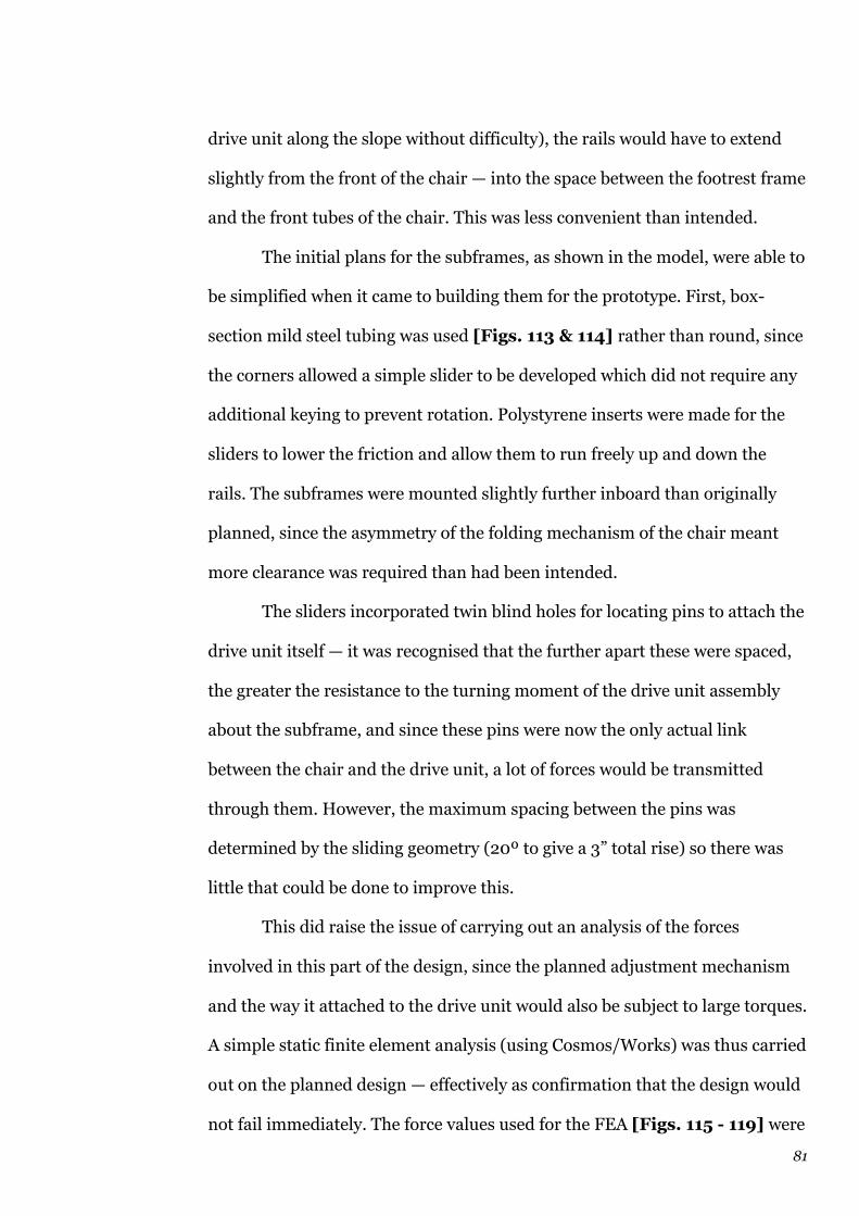
81
drive unit along the slope without difficulty), the rails would have to extend
slightly from the front of the chair — into the space between the footrest frame
and the front tubes of the chair. This was less convenient than intended.
The initial plans for the subframes, as shown in the model, were able to
be simplified when it came to building them for the prototype. First, box-
section mild steel tubing was used [Figs. 113 & 114] rather than round, since
the corners allowed a simple slider to be developed which did not require any
additional keying to prevent rotation. Polystyrene inserts were made for the
sliders to lower the friction and allow them to run freely up and down the
rails. The subframes were mounted slightly further inboard than originally
planned, since the asymmetry of the folding mechanism of the chair meant
more clearance was required than had been intended.
The sliders incorporated twin blind holes for locating pins to attach the
drive unit itself — it was recognised that the further apart these were spaced,
the greater the resistance to the turning moment of the drive unit assembly
about the subframe, and since these pins were now the only actual link
between the chair and the drive unit, a lot of forces would be transmitted
through them. However, the maximum spacing between the pins was
determined by the sliding geometry (20º to give a 3” total rise) so there was
little that could be done to improve this.
This did raise the issue of carrying out an analysis of the forces
involved in this part of the design, since the planned adjustment mechanism
and the way it attached to the drive unit would also be subject to large torques.
A simple static finite element analysis (using Cosmos/Works) was thus carried
out on the planned design — effectively as confirmation that the design would
not fail immediately. The force values used for the FEA [Figs. 115 - 119] were

Fig 113 – Lifting rails and sliders
Fig 114 – Lifting rails and sliders

Fig 115 – FEA on width adjuster assembly
Fig 116 – FEA on width adjuster assembly

Fig 117 – FEA on width adjuster assembly
Fig 118 – FEA on width adjuster assembly

Fig 119 – FEA on width adjuster assembly
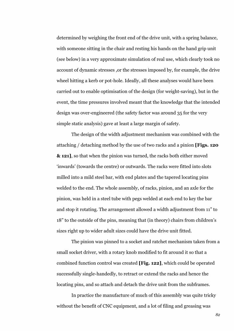
82
determined by weighing the front end of the drive unit, with a spring balance,
with someone sitting in the chair and resting his hands on the hand grip unit
(see below) in a very approximate simulation of real use, which clearly took no
account of dynamic stresses ,or the stresses imposed by, for example, the drive
wheel hitting a kerb or pot-hole. Ideally, all these analyses would have been
carried out to enable optimisation of the design (for weight-saving), but in the
event, the time pressures involved meant that the knowledge that the intended
design was over-engineered (the safety factor was around 35 for the very
simple static analysis) gave at least a large margin of safety.
The design of the width adjustment mechanism was combined with the
attaching / detaching method by the use of two racks and a pinion [Figs. 120
& 121], so that when the pinion was turned, the racks both either moved
‘inwards’ (towards the centre) or outwards. The racks were fitted into slots
milled into a mild steel bar, with end plates and the tapered locating pins
welded to the end. The whole assembly, of racks, pinion, and an axle for the
pinion, was held in a steel tube with pegs welded at each end to key the bar
and stop it rotating. The arrangement allowed a width adjustment from 11” to
18” to the outside of the pins, meaning that (in theory) chairs from children’s
sizes right up to wider adult sizes could have the drive unit fitted.
The pinion was pinned to a socket and ratchet mechanism taken from a
small socket driver, with a rotary knob modified to fit around it so that a
combined function control was created [Fig. 122], which could be operated
successfully single-handedly, to retract or extend the racks and hence the
locating pins, and so attach and detach the drive unit from the subframes.
In practice the manufacture of much of this assembly was quite tricky
without the benefit of CNC equipment, and a lot of filing and greasing was

Fig 120 – Width adjuster assembly
Fig 121 – Width adjuster assembly

Fig 122 – Width adjuster ratcheted knob
Fig 123 – Tilting control hand-grip

83
required before the assembly would run and operate smoothly. Even after this,
a number of parts broke during testing and required re-welding, each time
distorting the dimensions slightly further and worsening the fit. The final
prototype mechanism is thus quite stiff to operate, but it does demonstrate the
principle.
A box-section frame was built up and bolted to the top of the drive unit
castor bearing plate to hold the width adjuster assembly — the bolted
construction rather than welding was, in this case, very sensible, since it had
to be removed and dismantled about ten times during testing of the prototype.
(3.3) User interface
This had the potential to be one of the most interesting and rewarding parts of
the project, and yet unfortunately due mainly to time constraints, it was not
developed to anywhere near the standard hoped for.
Following the simple hand-grip style interface used on the January
prototype, an equally simple vertical tube design was attempted, with an
internal microswitch and spring so that the user tilted the hand-grip back
towards him or herself to operate the accelerator, and when released it tilted
forwards and power was automatically cut. [Fig. 123] This was inspired by
the Citroën ‘PRN satellite” column stalks used for many years, incorporating a
variety of functions in one multi-way single-handed switch. Other controls for
the wheelchair drive (cruise control setting, reverse / forward setting) would
be positioned around the hand-grip tube conveniently so that everything could
be done with one hand (either right or left).
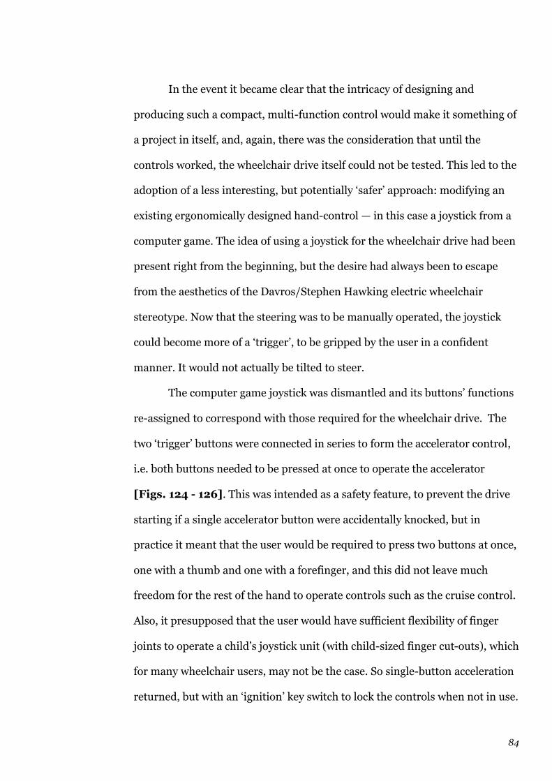
84
In the event it became clear that the intricacy of designing and
producing such a compact, multi-function control would make it something of
a project in itself, and, again, there was the consideration that until the
controls worked, the wheelchair drive itself could not be tested. This led to the
adoption of a less interesting, but potentially ‘safer’ approach: modifying an
existing ergonomically designed hand-control — in this case a joystick from a
computer game. The idea of using a joystick for the wheelchair drive had been
present right from the beginning, but the desire had always been to escape
from the aesthetics of the Davros/Stephen Hawking electric wheelchair
stereotype. Now that the steering was to be manually operated, the joystick
could become more of a ‘trigger’, to be gripped by the user in a confident
manner. It would not actually be tilted to steer.
The computer game joystick was dismantled and its buttons’ functions
re-assigned to correspond with those required for the wheelchair drive. The
two ‘trigger’ buttons were connected in series to form the accelerator control,
i.e. both buttons needed to be pressed at once to operate the accelerator
[Figs. 124 - 126]. This was intended as a safety feature, to prevent the drive
starting if a single accelerator button were accidentally knocked, but in
practice it meant that the user would be required to press two buttons at once,
one with a thumb and one with a forefinger, and this did not leave much
freedom f0r the rest of the hand to operate controls such as the cruise control.
Also, it presupposed that the user would have sufficient flexibility of finger
joints to operate a child’s joystick unit (with child-sized finger cut-outs), which
for many wheelchair users, may not be the case. So single-button acceleration
returned, but with an ‘ignition’ key switch to lock the controls when not in use.
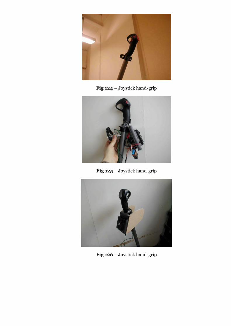
Fig 124 – Joystick hand-grip
Fig 125 – Joystick hand-grip
Fig 126 – Joystick hand-grip

85
Ultimately, the joystick design was developed considerably during the
testing process, gaining some sensible features to enable true single-handed
control (such as a rotary cruise control, and reverse/forward direction control
mounted on the joystick itself), but in adding other features, the joystick lost
much of its simplicity and became a rather bulky, ugly control box adorning
the top of the steering column. The final list of features included on this single
unit [Fig. 127] was:
— Accelerator momentary button
— Reverse / forwards select button
— Cruise control rotary switch (10 kΩ linear pot)
— Ignition key switch (cuts all power to the control unit)
— Horn momentary button (horn is Class 1 sounder from RS – suitable
for warning
pedestrians but not intrusive)
— Visibility lamp on/off button (the lamp is a halogen bulb, intended
to make the wheelchair drive visible/noticeable, but certainly not
intended to be used as a ‘headlight’)
— LCD battery gauge and momentary button (this is potentially an
extremely important usability feature – most existing wheelchair
drives, such as the Sinclair, do not have any kind of battery voltage
indicator, so the user or attendant may be completely unaware that the
battery needs charging until drive fails whilst out on a trip). The
voltmeter function on this feature was derived from a multimeter
disassembled and hard-wired to the 200 V range

Fig 127 – Joystick hand-grip
86
— Reversing alarm on/off button. The reversing alarm is made from
two different sounders connected in parallel, with a diode in series,
backwards across the motor, so that when the motor is driving in
reverse, the PWM is applied to the sounders to produce a distinctive
sound. The on/off switch allows the alarm to be disabled in areas
where it would be embarrassing or undesirable, e.g. a hospital ward,
changing room or toilet
Overall, the user interface has not been an especially satisfactory part of the
project, exacerbated by the attempt to provide some ‘styling’ by encasing it all
in a ‘binnacle’, taking its shape (rather loosely) from some of William Towns’
Interstyl car concepts. On the positive side, this enabled the wheelchair drive
to resemble a ‘real product’ a lot more closely for photography purposes, but
last-minute problems with the electronics (the controller) meant that most of
the work that had been done on the aesthetics and finish of this binnacle had
to be undone in cutting it in half to re-wire the controls and the resulting lash-
up resembled neither a functional prototype nor an aesthetic model.
Data were obtained on anthropometrics for adults52 and the elderly53,
as well as specific anthropometric and strength data for people with dexterity
disabilities54, which would have been ideal for designing and refining the
control interface analytically, but, again, there was not enough time to
investigate this properly.
Nevertheless, despite its deficiencies, the user interface developed for
the project does fulfil all the criteria intended — it can be used entirely single-
handed, it allows the user to keep his or her spine straight, and it is simple to
understand. Acceptable but not superlative.

87
(3.4) Battery choice
Reviewing the choice of battery technologies available for the project, it was
clear that the main issues to consider were:
— 24 V total
— Battery capacity and drain capabilities consistent with expected
usage patterns
— Low price
— Weight, to a lesser extent (depending on whether the batteries are
attached to the drive unit, or to the chair)
— Ease of recharging
— Envelope dimensions
The nominal battery capacity required was calculated using the XTi
motor specification data — 10 A continuous current drawn with the motor at
half power (e.g. with the wheelchair travelling along the level), used, stop-
start, over say a 3 hour shopping trip, maybe gives 1 hour continuous use, i.e.
10 A × 1 hour = 10 A hr. This value, despite being very approximate, does
compare to the battery capacities used in other wheelchair drive assistance
products, e.g. the Sinclair unit55 and Samson56 are 7 A hr, and the Alber
Viamobil57 is 12 A hr. From personal experience in discussing mobility aids
such as the wheelchair drive with potential customers, one of the first
questions asked will be “What is the range?” or “How far will it go before it has
to be recharged?”, and it is impossible difficult to answer this without knowing
88
full details of the usage patterns, speeds, obstacles encountered, battery
condition at the start, etc. Many manufacturers use ‘catch-all’ comments such
as (from TGA):
“You can attach it to any wheelchair... then glide along at up to 4 mph
with as much as 18 stone on board for up to 10 miles at a time before
you need to recharge the battery.”58
It is unlikely that the TGA battery can sustain this level of usage in
reality —
The unit has a 200 W, 12 V motor, thus assuming that the maximum
speed (4 mph) is achieved at maximum power consumption, the current
drawn is:
I = P / V = 200 / 12 = 17 A
10 miles at 4 mph = 2½ hours
2½ × 17 A = 42.5 A hr battery required
This is a bigger capacity than many car batteries. Even if a 24 V motor
were to be used instead, that would still mean that a 20+ A hr battery would
be needed, yet the TGA’s battery pack is little bigger than a Sinclair’s. So, it’s
clear that manufacturers’ claims for these products may well be exaggerated,
which seems particularly bad when dealing with a market where customers
often have little power to choose and where the product being bought really is
a necessity.
10 A hr was thus set as the minimum capacity required. The batteries
used up to this point had been two 7.4 A hr 12 V Yuasa sealed lead-acid gel
89
units (ex-Sinclair Zeta) — total capacity still 7.4 A hr since connected in series
to give 24 V total — and whilst the 10 A hr versions of these batteries (slightly
larger) were a likely contender, it was felt to be worth examining other battery
technologies — Nickel Metal Hydride and Nickel Cadmium. A spreadsheet was
prepared [Appendix] to calculate what would be the optimum number and
arrangement of various sizes of NiMH and NiCd batteries available from RS59,
in terms of cost and size, to achieve 24 V and 10 A hr. There was significant
difference in the numbers and costs involved, due mainly to the
‘multiplication’ nature of the exercise, e.g., only 20 × 1.2 V NiCd cells would be
needed to attain 24 V, but if they are only 1 A hr each (e.g. Sanyo High Pip
AA)60, then 10 will be needed in parallel, at each of the 20 tiers of 1.2 V cells,
giving an unrealistic total of 200 cells and a price tag of £472.
Ultimately, it was decided that since for even the cheapest non-lead
acid arrangement (5 × Saft 10XD NiCd), the price would be £300, it was much
more prudent to stick to lead acid, despite the large weight involved. The
challenge should be to make these convenient for the user, so that their weight
is not inconvenient and the benefits of the much lower price (comparatively,
less than £40 for two 10 A hr lead acid 12 V batteries) are realised.
(3.5) Controller casing
The plan was to incorporate the batteries within a neat, styled housing above
the wheel, on top of, or either side of, the width adjuster, along with the
controller PCB, horn and reversing alarm sounders, and wiring. Some ideas
were tried [Figs. 128 & 129] using aluminium section to house the batteries,
which would also act as a heat sink for the controller MOSFETs. Although the

Fig 128 – Controller / battery casing prototype
Fig 129 – Controller / battery casing sketches
90
dimensions were correct and the compact arrangement did fit, it was very
tight against the underneath of the seat, and could be felt when sitting in the
chair through the thin seat material. Equally, in that position, there was more
likelihood of spilling liquid onto the battery / controller unit — although it
would, of course, be properly sealed in production, it did not seem especially
safe.
An alternative position for the batteries was found towards the back of
the chair, on the rear frame on both sides — an area free of obstructions on
most wheelchairs. The battery bags used came from the Sinclair Zeta II again,
and whilst they could be replaced by more secure boxes or housings in
production, the degree of flexibility offered in terms of positioning (the chair
can still be folded with the batteries in place, and the cables do not become
trapped in the folding mechanism of the chair) meant that they were worth
retaining.
The controller PCB itself was mounted to a steel plate (to act as a heat
sink) ahead of the drive wheel [Figs. 130], with the substantial network of
connections made, and important interface features brought to the outside,
including:
— Charger socket (connected to the battery sockets)
— Battery sockets (one on each side of the wheel)
— Control socket (parallel port with connections for hand-grip
controls)
— Freewheel switch for motor
— Reverse/forward direction override switches for motor (to allow
testing, e.g. in the viva, if one MOSFET blows)
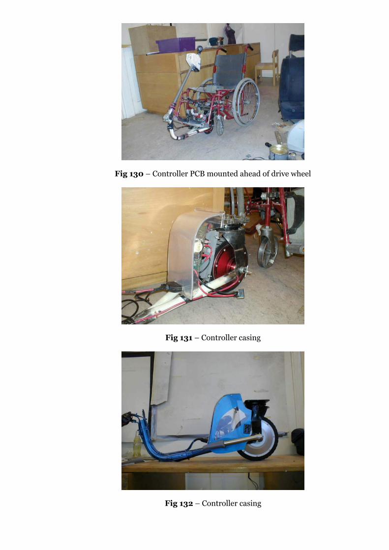
Fig 130 – Controller PCB mounted ahead of drive wheel
Fig 131 – Controller casing
Fig 132 – Controller casing
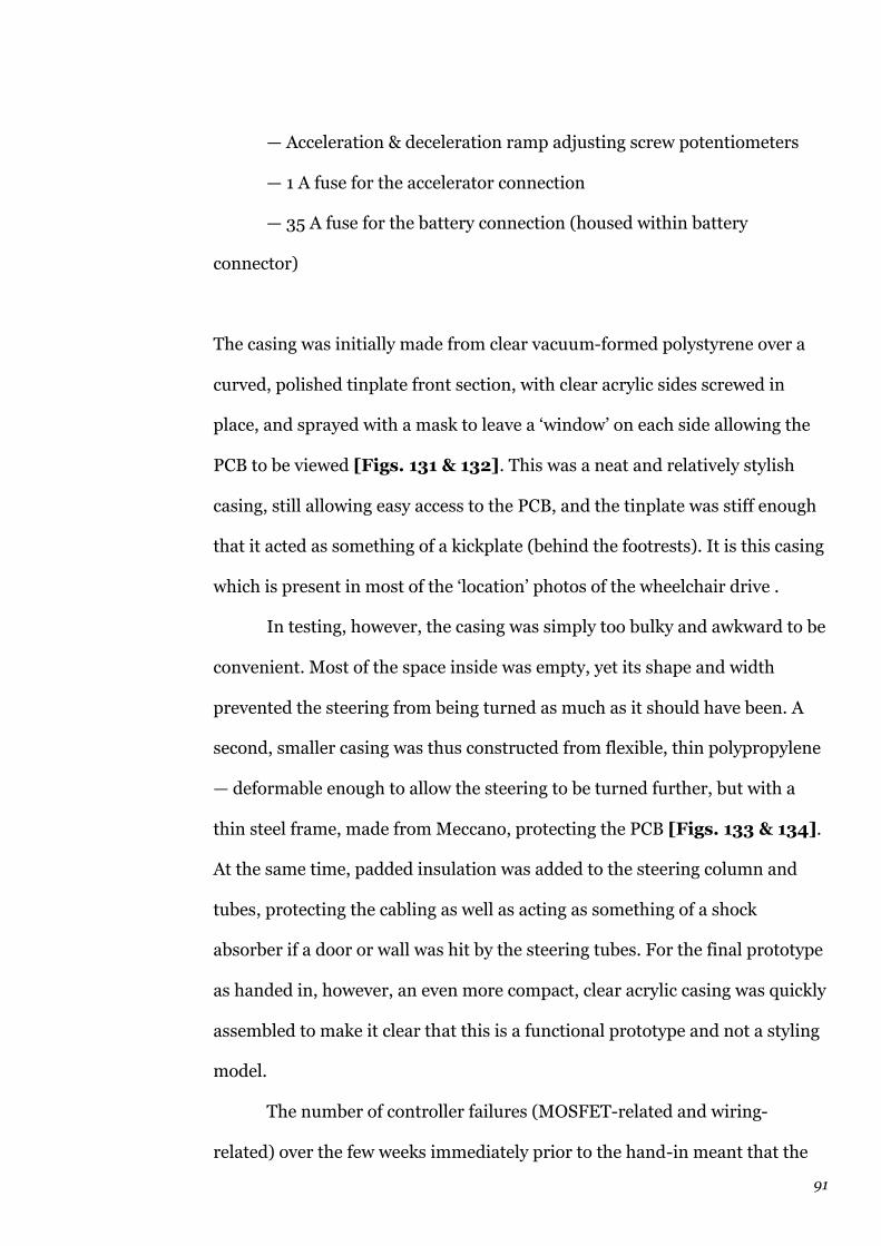
91
— Acceleration & deceleration ramp adjusting screw potentiometers
— 1 A fuse for the accelerator connection
— 35 A fuse for the battery connection (housed within battery
connector)
The casing was initially made from clear vacuum-formed polystyrene over a
curved, polished tinplate front section, with clear acrylic sides screwed in
place, and sprayed with a mask to leave a ‘window’ on each side allowing the
PCB to be viewed [Figs. 131 & 132]. This was a neat and relatively stylish
casing, still allowing easy access to the PCB, and the tinplate was stiff enough
that it acted as something of a kickplate (behind the footrests). It is this casing
which is present in most of the ‘location’ photos of the wheelchair drive .
In testing, however, the casing was simply too bulky and awkward to be
convenient. Most of the space inside was empty, yet its shape and width
prevented the steering from being turned as much as it should have been. A
second, smaller casing was thus constructed from flexible, thin polypropylene
— deformable enough to allow the steering to be turned further, but with a
thin steel frame, made from Meccano, protecting the PCB [Figs. 133 & 134].
At the same time, padded insulation was added to the steering column and
tubes, protecting the cabling as well as acting as something of a shock
absorber if a door or wall was hit by the steering tubes. For the final prototype
as handed in, however, an even more compact, clear acrylic casing was quickly
assembled to make it clear that this is a functional prototype and not a styling
model.
The number of controller failures (MOSFET-related and wiring-
related) over the few weeks immediately prior to the hand-in meant that the
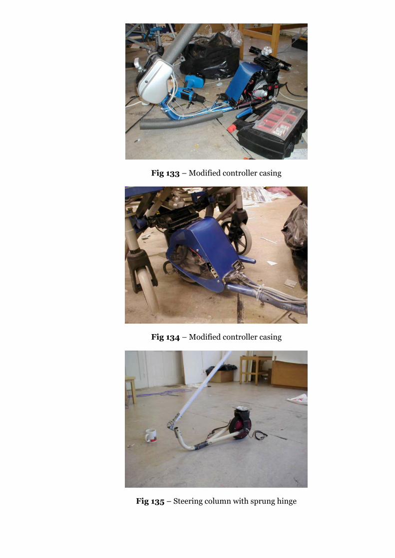
Fig 133 – Modified controller casing
Fig 134 – Modified controller casing
Fig 135 – Steering column with sprung hinge
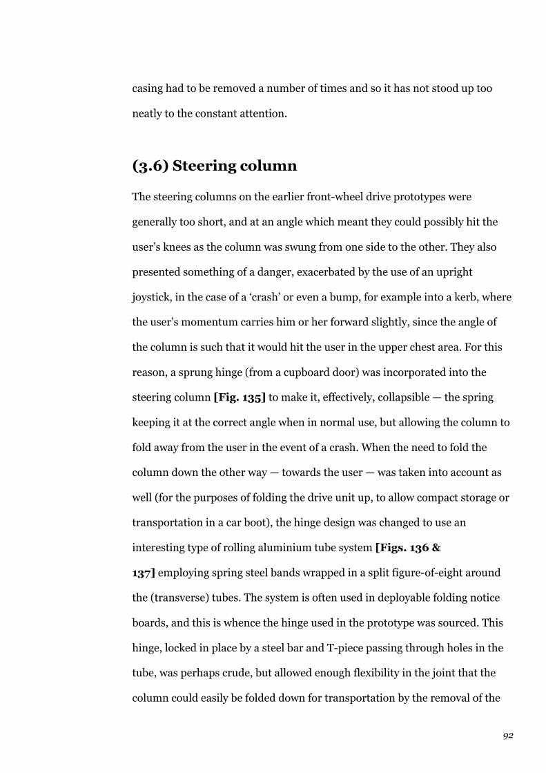
92
casing had to be removed a number of times and so it has not stood up too
neatly to the constant attention.
(3.6) Steering column
The steering columns on the earlier front-wheel drive prototypes were
generally too short, and at an angle which meant they could possibly hit the
user’s knees as the column was swung from one side to the other. They also
presented something of a danger, exacerbated by the use of an upright
joystick, in the case of a ‘crash’ or even a bump, for example into a kerb, where
the user’s momentum carries him or her forward slightly, since the angle of
the column is such that it would hit the user in the upper chest area. For this
reason, a sprung hinge (from a cupboard door) was incorporated into the
steering column [Fig. 135] to make it, effectively, collapsible — the spring
keeping it at the correct angle when in normal use, but allowing the column to
fold away from the user in the event of a crash. When the need to fold the
column down the other way — towards the user — was taken into account as
well (for the purposes of folding the drive unit up, to allow compact storage or
transportation in a car boot), the hinge design was changed to use an
interesting type of rolling aluminium tube system [Figs. 136 &
137] employing spring steel bands wrapped in a split figure-of-eight around
the (transverse) tubes. The system is often used in deployable folding notice
boards, and this is whence the hinge used in the prototype was sourced. This
hinge, locked in place by a steel bar and T-piece passing through holes in the
tube, was perhaps crude, but allowed enough flexibility in the joint that the
column could easily be folded down for transportation by the removal of the
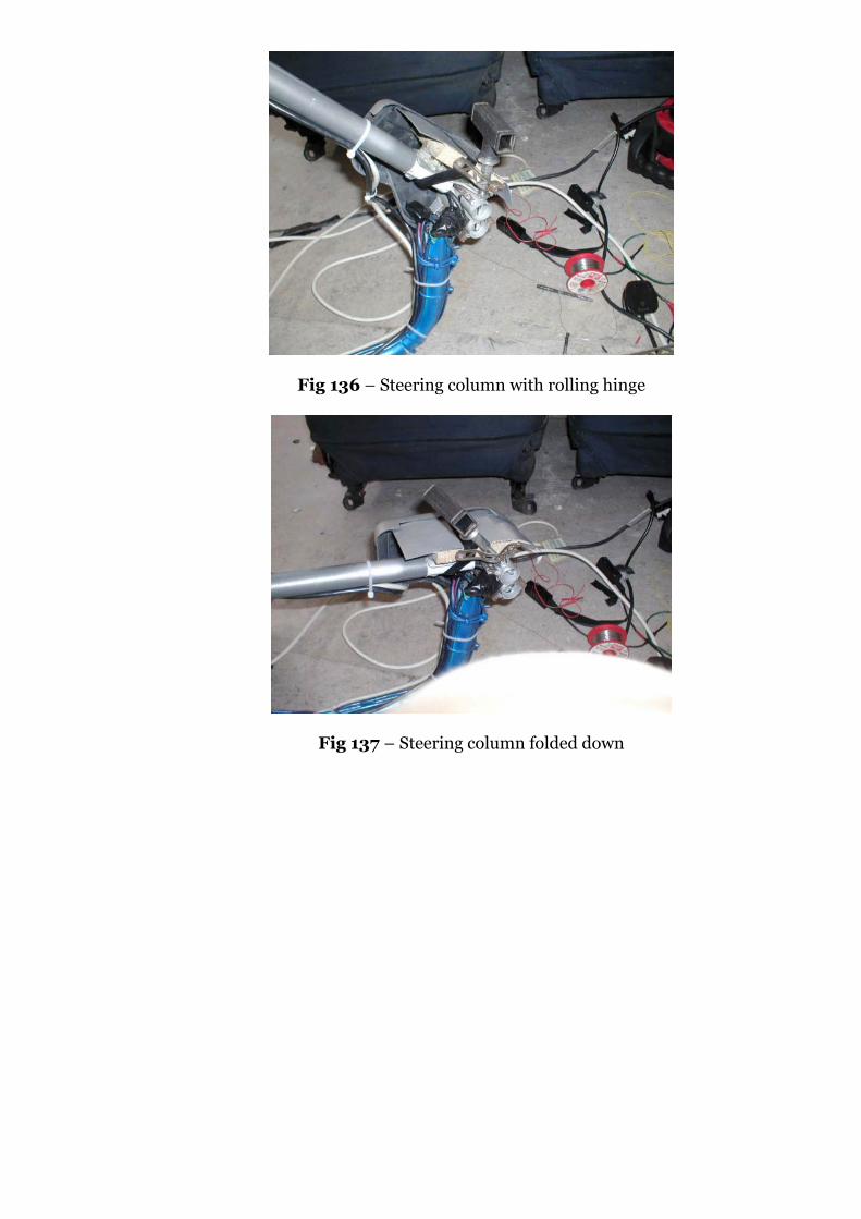
Fig 136 – Steering column with rolling hinge
Fig 137 – Steering column folded down
93
T-piece, and even with it in place, would spring forward on impact and pull
itself away from the user with some degree of safety. Remembering the 4 mph
maximum limit, the kinetic energy of the chair would never be especially high,
unless hit by another vehicle.
The steering column is height-adjustable with telescopic tubing, but the
hope that the excess cabling (needed when the column set to its tallest
position) would neatly stay tidy when the column was set to its lowest, was not
borne out. A flexible hollow casing was made from high-density polystyrene
and part of an ABS cover from a Rover 200 series car seat to protect the hinge
and locking mechanism, store the excess cable, and act as a bumper, but this
was bulky and somewhat ugly [Fig. 138] and has been removed from the
final prototype. The cables have been shortened on this prototype to improve
the appearance and prevent their becoming trapped when the column is
folded, and so this final prototype does not have an adjustable-height steering
column.
(3.7) User consultation
This has been something of a disappointment in the final stages of the project,
since the extensive user trials which were intended have not taken place
before the hand-in date. A number of arrangements were made but due to a
number of factors (some of them prototype-related, e.g. MOSFET failures,
welds breaking on the width adjuster and punctures on the chair tyres), they
have not come to fruition. For example, a meeting with wheelchair users and
the Disability Service at Uxbridge was cancelled at the last minute due to the
staff involved being called away, and a planned trial with a 12-year old

Fig 138 – Front ‘bumper’ / hinge housing

94
wheelchair user from Maidenhead, Sam Rhymes, was requested by his mother
to be delayed until after his SAT exams.
Most projects here at Brunel, unless developed in conjunction with
external companies, or by astute and well-organised students, do not receive
much user testing. This is a poor state of affairs, and this project has done
nothing to redress the balance, despite high hopes. The key problem was that
every time the prototype was tested here, some aspect failed to the extent that
it took a week or more to fix satisfactorily, by which time something else had
usually broken. The prototype is simply not well enough resolved to be up to
the testing procedures that Motivation or the QE Foundation would have put
it through, and this is disappointing. If the January prototype had been
developed as it was, with a stronger frame and improved ergonomics, but
none of the adjustability or lifting rails, etc., then the whole prototype would
probably have been finished by Easter, and could have been tested a lot more
thoroughly, but as it was, the drive to include more functions took over.
Many of the interested parties who have been involved with the project
over the year have been invited to Good Thinking : Brunel Design 04,
including OTs, mobility specialists, and wheelchair users who have
commented through e-mail and the website, and it is fully intended that they
will be able to try out the prototype and test it on the paving and ramps
around campus to destruction. Comments will be taken and the knowledge
will be appended to the report — of course, too late to be assessed, but there is
nothing to stop the device being developed further in the future.
The comments received via e-mail and in the guestbook on the website
over the year have been included in the Appendix of this report.
95
Evaluation
To some extent this report has been evaluative all the way through, but it is
only at the end that a real assessment can be attempted. There are a number
of themes into which the evaluation can be divided:
Evaluation of the final design
How suitable is the final design? It fulfils, to some extent at least, all of the
criteria in the specification, so in that sense, it should be judged a success. But
the compromises introduced by some of the design features (e.g. the whole
curved steering arrangement jutting out of the front) have possibly made the
design more unwieldy and awkward than it might have been. It certainly isn’t
an unobtrusive design, but that has to be weighed against the advantages it
offers the user. Is it better than the other wheelchair drives on the market? It
certainly offers more features than any others at the intended price level, but
is the pricing realistic?
Intended retail price: £600 (no VAT applicable to mobility products)
Rough costs: Motor ~ £100 inc. shipping, if ordered in quantity
Controller ~ £30 if ordered in quantity
Batteries ~ £30 if ordered in quantity
Electrical components ~ £15 if ordered in quantity
Materials ~ £50 if ordered in quantity
Total parts costs = £225, so £375 for labour, forming processes and
profit
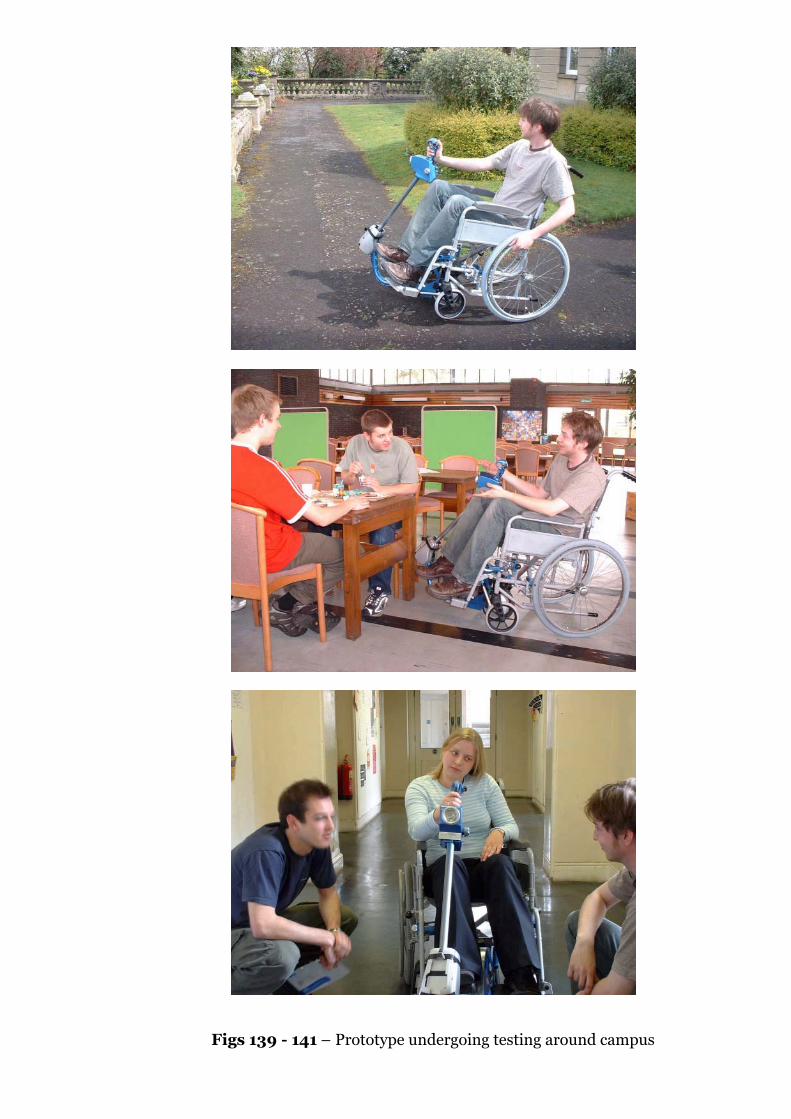
Figs 139 - 141 – Prototype undergoing testing around campus
96
Thus, it is certainly a feasible product cost-wise, and a manufacturer
already using tube-bending, welding, machining and plastic forming in its
other products could well add the wheelchair drive to the range at an even
lower price.
Many of the problems with the design come from working within a very
limited and constrained space and set of dimensions (i.e. the space under the
chair). This has very much shaped the design into its final form, with the
jutting steering being required to accommodate the user’s knees and the
footrests, and the position of the drive wheel quite a long way back again
coming from a need to avoid the parts of the frame which fold, along with
allowing space for the drive wheel to turn. In this sense, the achievement of a
mechanism (the subframes) which still allow the chair to fold, and can be
fitted to many wheelchairs with the benefit of the width adjuster on the drive
unit itself, could be considered quite impressive, despite its crudity.
What else could / should have been done? This is a possible sequence
of development that would have been ideal, given more time or less time spent
earlier in the project on other configurations, etc:
— Full dynamic stress analysis (Cosmos/Works and/or ADAMS/View)
of wheelchair with drive unit attached to simulate kerbs, pot-holes, etc
— Drive unit frame and materials optimised to lower weight within cost
parameters
— Redesigned drive unit produced accurately using CNC machining,
vacuum casting or other rapid manufacturing technologies
— User and expert testing and extensive trialling of the prototype(s) to
pick up defects and also allow an improved user interface to be
developed (probably radically different)
97
— Presentation of the drive unit at trade fairs, mobility exhibitions (e.g.
NAIDEX) to attract manufacturers’ attention
Apart from the cost issues of the prototype manufacture, all of this is (in
theory) within the author’s capabilities. It would require more in-depth
knowledge of Cosmos/Works and ADAMS, but these would be exceptionally
useful skills to develop. Again, though, such an ambitious plan almost
assumes that the design (in terms of configuration and basic layout) would be
pretty much resolved right at the start of the year, which was by no means the
case.
Design vs. prototyping
Much of this project has been designed through prototypes, i.e. by testing out
ideas for configurations and mechanisms physically, rather than the more
sequential design-then-manufacture process. Of course, some of the more
complex details such as the sliding rails and the width adjuster mechanism
were planned on paper first (and more usefully, in a 3D Solidworks assembly
model, which evolved and was updated throughout the process), but much of
the spatial layout of the designs, right from the early prototypes, was done
entirely in situ, on the chair itself. Whilst this has meant that a much larger
number of prototype iterations was possible, with an enormous number of
different ideas tried, and the final hand-in artefact representing only a fraction
of the artefacts that have been developed, dismantled, developed again, etc.,
over the year, it also means that there is less traceability from one stage of the
design to the next. In a conventional modern design and development

Figs 142 - 143 – Prototype undergoing testing around campus
98
environment, this would be unthinkable, but it could well be argued that
within the early stages of developing concepts to the stage where they can
actually be ‘designed’ to become products, physical lash-ups and mock-ups are
a valuable tool.
Preston G. Smith, in an article in the InKNOWations electronic
newsletter, gave an interesting perspective on this:
“The key is to make plenty of prototypes, keep them each as simple
as possible, and make and assess them quickly... keep each prototype
as crude as you possibly can to resolve only its hypothesis... when a
prototype has answered its question, toss it and plan the next round of
prototyping. Recognize that, if you are doing it well, the majority of
your prototypes will be failures, illuminating a route down which you
do not wish to proceed. Keeping your prototypes simple — even crude
— will be a challenge. We all like to burnish our work, and executives
may believe that a sloppy prototype reflects sloppy thinking. For
instance, the revered product development firm IDEO is known for its
prototyping effectiveness. But if you examine Tom Kelley’s book about
IDEO, The Art of Innovation (Doubleday, 2001), you will find only
burnished prototypes among its many beautiful illustrations. Even
IDEO has difficulty revealing an ugly prototype.”60
Sloppiness has gone as far in the Kelleys’ thinking to be included in
their ‘FLOSS’ mentality, but perhaps the problem with this wheelchair drive as
a major project is that it has never been satisfactorily developed beyond the
‘sloppy’ stage. This issue will be addressed again in the section on ‘Personal
99
development’ below, but it should probably suffice to say that there were
simply too many features included in this project to hope to have them all
resolved beyond a sloppy prototype stage by the time of the hand-in.
Could the project have been done in the design-then-manufacture
style? Could everything have been planned on paper and the plans taken down
to the workshops sometime in April and the whole thing constructed and it be
perfect, or at least better than what was actually handed in? Better visually,
better aesthetically, probably, but whether as much would have been learned
about the issues involved is debatable. From the author’s point of view, this
was a project that absolutely had to be developed physically at every stage.
In terms of specific problems, one day a week for the Fabrication
workshop was a particularly appalling state of affairs, since not only was
welding an important part of this project, but only once a week could a
bandsaw be used for steel due to being positioned in the Fabrication shop.
This restriction on use of the workshop led to the situation of having a week’s
artificial delay any time any part broke or required improving, led to missing
ESD lectures every single week to make the most of the time in the workshop,
led to inordinate amounts of poorly hacksawed steel parts, and led to hiring an
electric welder from Egham twice and using it in the kitchens in Scrivens.
Breakpoints
Was there a ‘breakpoint’ in the project? This is a question that has been in the
air for a while. The major turning point in the project was in November when
the decision was made to try a front-wheel drive arrangement instead of the
100
rear-driven prototypes which had thus far been developed. Was this the right
decision?
From the educational point of view, certainly ‘Yes’, since more has been
learned about steering, castor angles, and what works and what doesn’t work
generally, than would have been by sticking to one of the concepts already
developed at that point. But the rear-wheel drive XTi motor prototype, with its
powered steering, was not bad — certainly it was much more compact, much
less intrusive, less highly stressed, much simpler, probably much cheaper to
build, and — already by that stage — more resolved as a ‘product’ than the
later prototypes. From a product point of view, it is this prototype which
should have been developed into the final product. The issues over the safety
and control interface for the steering would have been solved through learning
more about perception, user interfaces and ergonomics and by May 14th, the
project may well have been resolved enough to be a product, tested and
trialled by users rather than a project still being worked on.
Another breakpoint was the prototype as displayed at the January viva.
This prototype had almost all the features that the final prototype has, but
without the width adjustment or sliding attachment and detachment
functions. Again, if this had been developed as it was, with more time to pay
attention to the user interface, it could have been a usable product much
earlier.
But then it wouldn’t have fulfilled all the criteria set right at the
beginning, in the specification, and these criteria were not put there as
ramped ‘possible directions’ — they were there because to be a better product
than everything else in this market, any new device would have to meet them
all. And the final prototype makes a fairly good attempt at that.

Evol
utio
nof
the
desi
gnth
roug
hpr
otot
ype
deve
lopm
ent,
rang
ing
from
rear
-whe
elst
eere
dde
vice
sto
curr
ent‘
scoo
ter
styl
e’fr
ont-
mou
nted
unit
105
References
1. Stannah website, www.stannah.co.uk, March 2003
2. ibid.
3. KALOGROULIS, Alexander and LOCKTON, Daniel (2003): Sinclair
ZA20 Wheelchair Drive Unit User Manual, Daka Research (UK) Ltd.
4. Alber website, www.ulrich-alber.de, August 2003
5. Price list from Gerald Simonds Healthcare, Aylesbury, Bucks, August
2003
6. Report produced for initial application available at
www.brunel.ac.uk/~dt00ddl/wheelchair/report_august_2003.pdf
7. CLARK, Laura L (1997): Design and testing of a quick-connect
wheelchair power add-on unit, Virginia Polytechnic Institute, US (ref.
no. ETD-12898-174432)
8. ibid.
9. Matrix available online at
www.brunel.ac.uk/~dt00ddl/wheelchair/matrix.pdf
10. Received from manufacturers and distributors, and collected at
exhibitions
11. Sinclair Research website, www.sinclair-research.co.uk, December
2003
12. KVB Manufacturing website, www.kvb.com, October 2003
13. Brochure received from TGA Electric Leisure, Sudbury, Suffolk, August
2003
14. Alber website, www.ulrich-alber.de, August 2003
106
15. GOLDTHORPE, Richard (1993): Major Project Report, Brunel
University, Runnymede
16. WEISZ, Erwin (2002): Electric Wheelchair Drive System, US Patent
6,494,278
17. Brochure received from Quay Motors, Exeter, Devon, September 1996
18. Brochure received from TGA Electric Leisure, Sudbury, Suffolk, August
2003
19. GAAL and JOHNSON(1993): Evaluation of wheelchair power
assistance units, Wheeled Mobility Center, San Francisco State
University, US, quoted in ref. 7
20.BMC>Rover Online website, www.austin-rover.co.uk, December 2003
21. Personal conversation between Geoffrey Gane, Mark Coleman and the
author, October 2003
22.Remploy website, www.remploy.co.uk, January 2004
23.Disabled Living Foundation website, www.dlf.org.uk, September 2003
24.CLARK, Laura L (1997): Design and testing of a quick-connect
wheelchair power add-on unit, Virginia Polytechnic Institute, US (ref.
no. ETD-12898-174432)
25. Paraplegic Online website, www.paraplegic-
online.com/edefinition01.htm
26.Contextual Design lecture by Sarah Beattie at Brunel University,
Runnymede, December 2003
27. Motivation website, www.motivation.org.uk, September 2003
28.LOCKTON, Daniel (2003): Motors, Daka Research (UK) Ltd.
29.Golden Island Motors website, www.goldenmotor.com, July 2003
30.Comment in guestbook at www.wheelchairdrive.vze.com, October 2003
107
31. Assembled Products Corporation website, www.martcart.com, August
2003
32.E-mail to author, November 2003
33.Brochure from Sinclair Research Ltd., August 2002
34.HEBRA, Alex (2003): Measure for Measure, Johns Hopkins University
Press, Maryland, US
35. Contextual Design lecture by Sarah Beattie at Brunel University,
Runnymede, December 2003
36.Remploy website, www.remploy.co.uk, July 2003
37. PEEBLES, Laura and NORRIS, Beverley (1998): Adultdata,
Department of Trade & Industry
38.4QD website, www.4qd.co.uk, October 2003
39. ibid.
40.ibid.
41. Telephone discussion with David Constantine, October 2003
42. ibid.
43.Contextual Design lecture by Sarah Beattie at Brunel University,
Runnymede, December 2003
44.Project website, www.wheelchairdrive.vze.com
45. Personal conversation between David Jackson and the author,
November 2003
46.JACKSON, David (2001) Invalid chair with propulsion unit, GB Patent
Application no. 2378929
47. Battery Vehicle Review, Battery Vehicle Society, Milton Keynes,
December 2003
48.E-mail to author, December 2003

108
49.The Use of Invalid Carriages on Highways Regulations 1988,
Statutory Instrument 1988 No. 2268, Her Majesty’s Stationery Office
50.ibid.
51. TORRENS, Richard (2003) NCC Series Controllers – Instruction
Manual, 4QD, Cambridge
52. PEEBLES, Laura and NORRIS, Beverley (1998): Adultdata,
Department of Trade & Industry
53. PEEBLES, Laura, NORRIS, Beverley and SMITH, Stuart (2000): Older
Adultdata, Department of Trade & Industry
54. FEENEY, Robert (2002): Specific anthropometric and strength data
for people with dexterity disability, Department of Trade & Industry
55. Brochure from Sinclair Research Ltd., August 2002
56. Brochure received from PDQ Mobility Ltd., May 2003
57. Brochure received from Ulrich Alber GmbH, May 2003
58.Brochure received from TGA Electric Leisure, Sudbury, Suffolk, August
2003
59. Catalogue from RS Components Ltd, February 2004
60. SMITH, Preston G. (2004): Article in InKNOWations newsletter,
January 2004
61. PARKINSON, Cecil Northcote (1958): Parkinson’s Law, or the Pursuit
of Progress, Penguin Books, Harmondsworth