what‘s new in simufact.forming 14 - netformmetal.com · simufact.forming hub upgraded ......
TRANSCRIPT

What‘s new in
Simufact.forming 14.0

Highlights
New view for pre- & postprocessing
General model setup improvements
Improved application modules
Pressure welding
Mechanical joining
Meshing improvements
Improved optimization functionalities
Improved robustness
Updated documentation

Simufact.forming hub upgraded
Application module „Rolling“ was added to the
Simufact.forming hub:
No additional license is required.

New view for pre- & postprocessing
Fast
Intuitive
Interactive
Focus on the results
Increase productivity
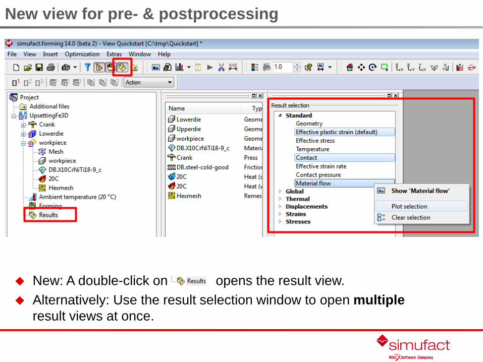
New view for pre- & postprocessing
New: A double-click on opens the result view.
Alternatively: Use the result selection window to open multiple
result views at once.

New view for pre- & postprocessing
Change displayed result value by mouse click on legend title:

New view for pre- & postprocessing
Mouse interactions:
Pan: click + hold left button
Zoom: rotate mouse wheel or click + hold middle button
Rotate: click + hold right button
Keyboard shortcuts:

New view for pre- & postprocessing
Context menu on object provides quick access to:
Change rotation point / center
Change view mode ofclicked component
Functionality applying toentire view

New view for pre- & postprocessing
Context menu on background provides quick access to:
Change colors
Change view mode for all components(including invisible components)
Functionality applying to entire view

New view for pre- & postprocessing
Context menu on legend provides quick access:
min. / max. ofall result steps
Notes: The color legend properties are changed only for the current session To change the properties permanently, use: Extras Options Global settings Results

New view for pre- & postprocessing
Pre-defined color schemes for comparison of results with
previous versions:
Identical colors e.g.for version validationpurposes
Discrete legend only
New view for pre- & postprocessing
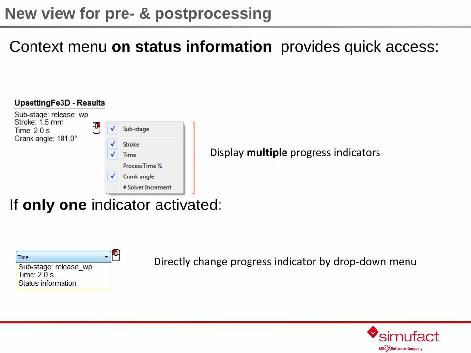
Context menu on status information provides quick access:
If only one indicator activated:
Display multiple progress indicators
Directly change progress indicator by drop-down menu
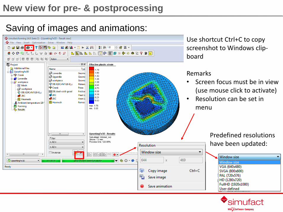
New view for pre- & postprocessing
Saving of images and animations:
Predefined resolutionshave been updated:
Use shortcut Ctrl+C to copyscreenshot to Windows clip-board
Remarks• Screen focus must be in view
(use mouse click to activate)• Resolution can be set in
menu

New view for pre- & postprocessing
Synchronization of result and model views was
updated:
View
Result step
Legend
Synchronize views once by click on main icon:
Permanent synchronization is still available If permanent synchronization is deactivated, the view does not anymore jump back to last
unsynchronized settings Synchronization of model and result view is supported

New view for pre- & postprocessing
Clipping:
Unified clipping function for the model and result view
Add / remove clipping plane
Show full model Contour Hide plane Cross sectionSwap direction
Note: Radial clipping will be added in a future release again.

New view for pre- & postprocessing
Clipping:
The result values are shown without interpolation artifacts
Context menu for saving• Clipping definition• Cut geometry

New view for pre- & postprocessing
Positioning:
Access positioning from context menu in model view
Positioning can be done while clipping activated
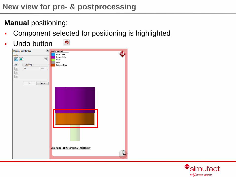
New view for pre- & postprocessing
Manual positioning:
Component selected for positioning is highlighted
Undo button

General improvements
CAD import was updated to CADfix version 10.0. The following file formats are supported:
IGES (*.igs *.ige *.iges)
STL (*.stl *.sta *.stb)
Step (*.stp *.step)
Creo up to version 3.0 (*.prt* *.asm* *.g *.xpr *.xas *.neu)
CATIA V5 (*.CATPart *.CATProduct)
CATIA V4 (*.model *.exp *.dlv *.dlv3 *.session)
NX 9 Unigraphics (*.prt)
SolidWorks up to version 2014 (*.sldprt *.sldasm)
Inventor up to version 2015 (*.ipt *.iam)
VDAFS (*.vda)
ACIS (*.sat *.sab)
Parasolid up to version 27(*.x_t *.xmt_txt *.x_b)
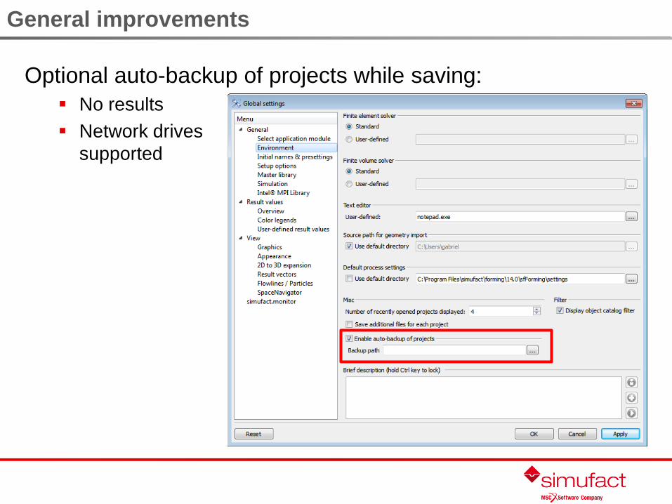
General improvements
Optional auto-backup of projects while saving:
No results
Network drives
supported

General improvements
Translations and rotations of a component can be reset:
No need to remove the geometry first
Confirmation needed

General improvements
Particles (single points) can be imported from CSV files:
General improvements
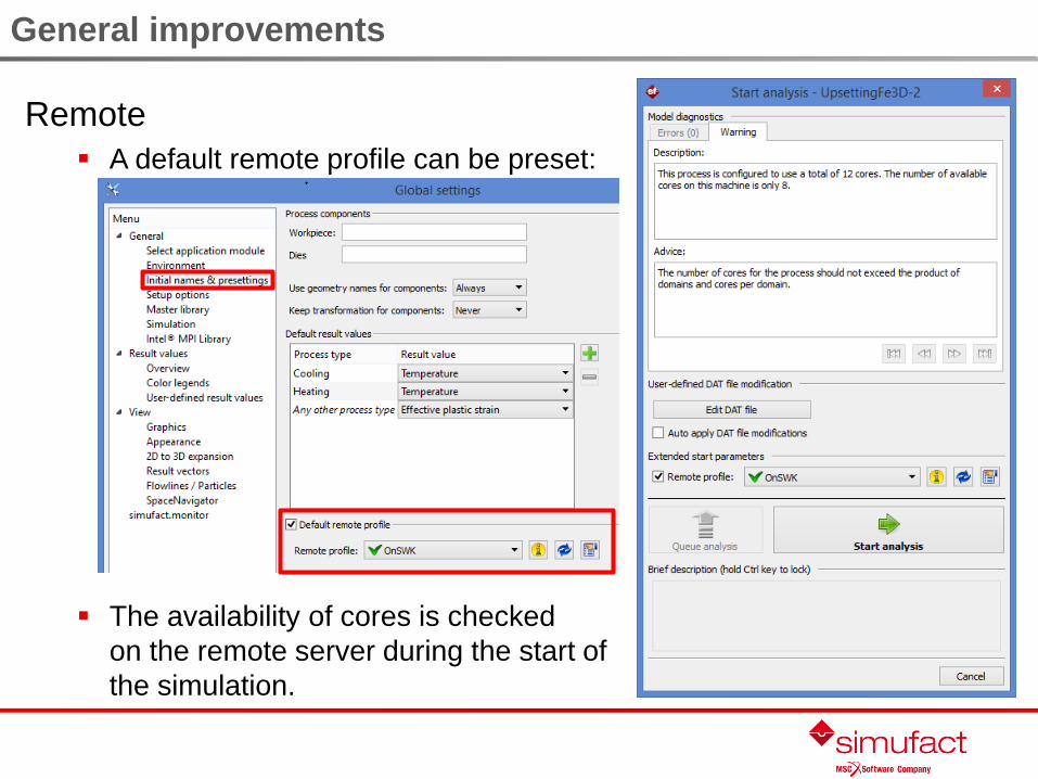
Remote
A default remote profile can be preset:
The availability of cores is checked
on the remote server during the start of
the simulation.

General improvements
Rigid dies with heat conduction can be used as trimming
dies:
Trimming (before/only)
Trimming while forming

General improvements
The progress display was improved:
Individual process
Multiblow (hammer and screw presses)
Stage control
Incorrect status information, e.g. if terminated on press force, was
corrected

General improvements
Improved calculation of automatic heat transfer coefficient:
Now material properties of both
contacting partners are considered.

General improvements
Material database:
The material group „tool steel“ is limited to materials for deformable dies (elastic). Materials suited for metal forming simulations were moved to “General steel”
New materials for sheet metal forming at room temperature: BH210
BH280
BH300
BH340
DDQ
DP500
DP600
DP800
DQSK
HCT600XD
HCT780C
HS440WGA
HSLA350
HSS590
IF
MS1400
TRIP590
TRIP600
TRIP780
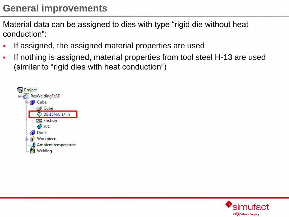
General improvements
Material data can be assigned to dies with type “rigid die without heat
conduction”:
If assigned, the assigned material properties are used
If nothing is assigned, material properties from tool steel H-13 are used
(similar to “rigid dies with heat conduction”)

General improvements
Result value contact status:
Contact to symmetries added
Uniform for FE and FV solvers
Result tree restructured:

General improvements
New result value error element:
Indicates “inside-out” elements
Use element filter to show only
the inside-out elements and their
direct neighbors
Belongs to “standard” result group

General improvements
Usability of comparison view in THS plots was improved:
Imported data can be activated & deactivated from selection.

General improvements
For simulations using a counter blow hammer and the FV
solver all energies (gross/net available/delivered) are always
shown for the entire press. It is not anymore necessary to
summarize the individual tool energies.

Sub-stages
Backstroke:
May now be larger than 100%, input may be given as distance, e.g. in mm
Can be used in combination with terminate on tool forces
Can be used if die positioned at BDC and automatic positioning of tool used

Meshing
Improved self-contact:
Hexmesh
C folds ok
V folds instable as sharp folds
will create geometries impossible
to be hex-meshed particularly if
sharp edges are detected
Tetmesh will be
improved further in upcoming
versions
Example of large fold meshed with Hexmesh

Meshing
Remeshing can be controlled:
Based on criteria (default)
Only forced
Never (simulation will stop debugging)
Adaptive mesh refinement, type “contact”
Symmetries do not cause refinement
anymore.
Tools will be selectable by user
[development ongoing].
Symmetry

Hot forging (FV solver)
Multiple (segmented) dies can be
used also for screw and hammer
presses.
Time-ramp-up is supported also for screw presses.
Effectively reduces the force peak at initial tool contact.

Hot forging (FV solver)
New termination criterion on tool forces added:
Stops the simulation when given tool force is exceeded
Should be used together with solver step control „time
ramp up“

Mechanical joining
New process types self-piercing riveting, punch riveting,
blind riveting and tensile test
Optimized initial and advanced settings
Automatic measuring (self-piercing riveting and clinching)

Mechanical joining
New additional termination criteria:
Self-piercing riveting
Clinching

Mechanical joining
If the sub-stage “release workpiece from stationary dies” is used, all
sheets and adhesive layers are excluded from the release as a default
setting.
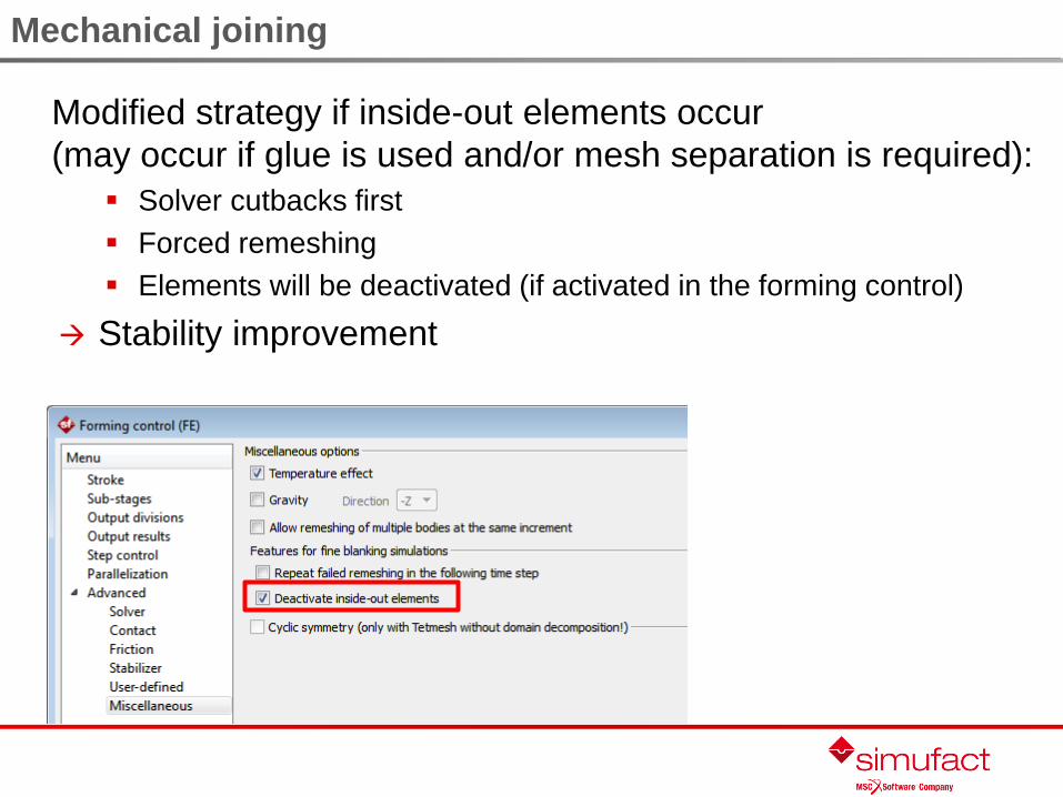
Mechanical joining
Modified strategy if inside-out elements occur
(may occur if glue is used and/or mesh separation is required):
Solver cutbacks first
Forced remeshing
Elements will be deactivated (if activated in the forming control)
Stability improvement

Pressure welding
New result value: Automatically calculated electrical contact
coefficient
New contact type for resistance spot welding:
temperature drops from melting to solidus temperature
contact glued
Added support for segment-to-segment contact for
application module pressure welding
Electrical material properties (phase-dependent) can be
imported from JMatPro

Optimization
Any object attached to the process tree can be exchanged
in a serial examination and optimization

Optimization
Use “create all optimization cases” to create and start the
simulation of (many) variants:

Optimization
Serial examinations
Can be carried out running several simulations simultaneously (if
licenses available).
A failed simulation will not stop the serial examination or
optimization run anymore.
For selected process types the components can be positioned
automatically.

Not only for optimization
Auto-positioning for initial positioning
for selected processes:
Friction spot welding
Spot welding
Self-piercing riveting
Notes
Positioning is done by translation along
global z-axis.
Lowest component is used as reference
(position is not changed).
Component roles for self-piercing
riveting must be defined. Components
without roles (e.g. fixings) cannot
be positioned.
Rivet is not positioned but punch
is positioned on rivet's top.

Not only for optimization
The initial meshing (in addition to remeshing) settings are
kept if the geometry is exchanged.

Process chain simulations / interfaces
Import results from casting simulation with Procast
Geometry
Temperature
Shrinkage porosity
Stress
Export only one geometry
and one step (increment)
per *.unv file
3D geometries only

Process chain simulations / interfaces
Import results from casting simulation with Procast
Import UNV files with „Geometry Mesh from file“
Unit of result values is read from UNV file and transferred to
Simufact.forming automatically
After importing the geometry, mesh + results are available in the
object catalog
Shrinkage porosity is converted into
relative density

Process chain simulations / interfaces
Export interface of simulated press forces to Brankamp
process monitoring systems:
Facilitate tool setup & increase die life
Use simulated results as a reference for production
Note: requires special license from Simufact and Brankamp

General improvements
In case of a GUI crash memory dumps are written to allow
easier debugging & customer support:
MemoryDump files saved in folder
%APPDATA%\simufact\MemoryDumps of the current user
No customer data (geometries, material data, etc.) are stored
Only activated if the setup was carried out with admin privileges
Top bugfixes
Blocked read-only access by the solver to CUR, HIST and RES files was fixed.
Incorrect stress transformation in dieload simulations with rotating dies fixed.
Several reasons for occasional GUI crashes were resolved.
Symmetry planes are now correctly transported to the next stage by the stage
control if “automatic workpiece symmetry” is used.
Not working output divisions based on stroke during backward stroke were fixed.
“Jumping” forces in remeshing time steps have been fixed.
Incorrectly shown validity in the license manager was corrected.
In total almost 400 bugs were fixed.

Top bugfixes
Resolved meshing issues
SurfaceMesher: Various issues like occasional memory leak and very long meshing
times or meshing failures have been resolved.
HexMesher: An error was resolved that under rare conditions produced a mesh with
holes on the surface.
Sheetmesher: Incorrect mesh produced if geometry to be meshed had small holes or
narrow notches was resolved.

Setup
Supported operating systems:
Windows 7 (64 bit), Windows 8 (64 bit)
Linux (64 bit): FormingGP GUI and solvers only (mainly tested on
RHEL 6.3 / CentOS 6.3)
Graphic card requirements:
OpenGL 2.1 or newer
Min. 1GB RAM on graphics card
Use newest driver available
Note:
If all colors are displayed grey when using the Windows remote
desktop or a Teamviewer session, the graphics card drivers need to be
updated on both computers.
Setup
Simufact.forming GP (as well as Project and
Quickpost) are installed with a separate setup
using a separate path and their own solver.

Setup
Settings have been made independent from installed version and can
be transferred to new versions when the GUI is opened for the first time:
The need to register with a password for the MPI service was removed:

Thank you for your attention!
simufact engineering gmbh
Tempowerkring 19
21079 Hamburg, Germany
Tel.: +49 (0)40 790 128 - 000
Fax: +49 (0)40 790 128 - 199
www.simufact.com