what is system analysis and design? • tools and …renaat/ca2/ca214/ca214ssadm.pdf · • what is...
TRANSCRIPT
Overview
• What is system analysis and design?• Tools and models• Methodologies
Information Systems
• What is a system?• Why do systems fail?• What is systems analysis and design?• How do we do systems analysis?

What is a system?
• A collection of parts• that work together• to achieve a goal/task
What is an information system?
• Parts?– Usually on of the parts is a computer
• Task?• The difficulty is getting the parts to work
together
Complexity in Systems
• IS are needed for large/complex tasks• Solve complexity by partitioning• More parts → More interaction• More interaction → Complexity

Bad Systems
• Fail to meet requirements• Poor performance• Poor reliability• Unusability
Badly Produced Systems
• Not to schedule• Not to budget• Runaway = 100% over budget or schedule
Reasons for Failure
• Complexity– Shifting requirements– Bad estimation– Bad management– New technology

Need for Structure
• Must tackle complexity• Structure partitioning of problem• Organised interaction of parts• Ensure you achieve the task

System Development Life Cycle
• An ordering of a set of system development activities/phases.
• Can be either sequential (serial) or non-sequential (e.g. contingent).
• Contains guidance on how to progress from one phase to the next

Generic development phases:Initiation
Development
Implementation
Operation &Maintenance
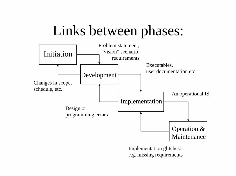
Links between phases:Problem statement;
“vision” scenario,requirements
Executables,user documentation etc
Changes in scope, schedule, etc.
An operational IS
Initiation
Development
Implementation
Operation &Maintenance
Design or programming errors
Implementation glitches:e.g. missing requirements
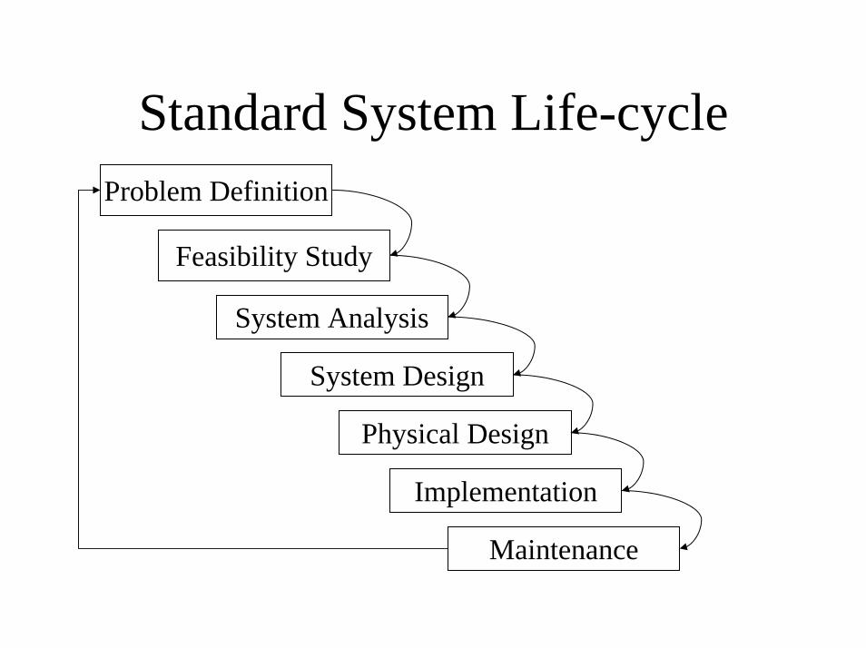
Standard System Life-cycleProblem Definition
Feasibility Study
System Analysis
System Design
Physical Design
Implementation
Maintenance
System Development Life-Cycle
• Stages ⇒ Milestones• Output/product/deliverable• Waterfall technique• Distilled experience

Systems Analysis and Design
• Central to the life-cycle• Analysis: defining the problem
– From requirements to specification• Design: solving the problem
– From specification to implementation
Models
• Representations• Simplify reality• Require training• Appropriate to problem
Models in Analysis and Design
• Focus ideas• Aid communication with user• Highlight omissions and errors• Blueprint for the system

Good Models
• Maintainable and disposable– CASE tools
• Graphics v. Text• Understandable
The Main Models
• Entity relationship diagram• Data-flow diagram• Entity life-history

Some Remarks
• All three models represent the same system• There is no unique correct model• Need more than one attempt
Case Studies
• Replace requirements• Informal• Ambiguous• Realistic! (Nearly)• Estate Agent System in handbook

Entity Relationship Diagrams
• Centrality of data– DBA and DA
• Represents structure of data• Shows relationships within data

Focus in ER diagrams
• Structured• Logical• Process independent• Minimal
Components of ER Diagram
• Entities with lists of attributes• Occurrences as set of values• Relationships
– two directions - two sentences– degree– optionality

Entity
• Block of information• Represents a type of thing• Occurrences are instances of the entity
Student
Attributes
• Belong to an entity• Simple item of data• Values are the data for an occurrence• Candidate keys and primary keys
Entities as Tables
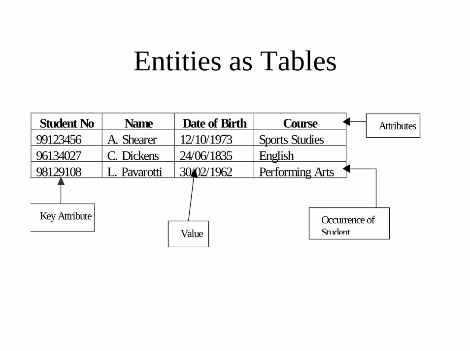
Student No Name Date of Birth Course99123456 A. Shearer 12/10/1973 Sports Studies96134027 C. Dickens 24/06/1835 English98129108 L. Pavarotti 30/02/1962 Performing Arts
Key Attribute
Attributes
ValueOccurrence ofStudent
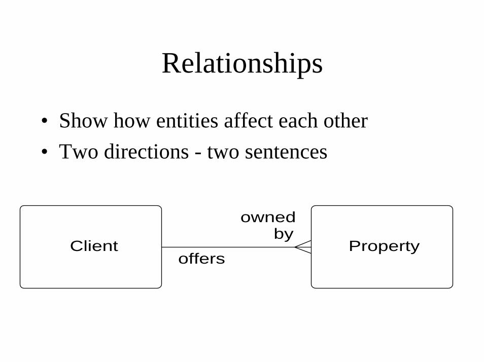
Relationships
• Show how entities affect each other• Two directions - two sentences
Client Propertyoffers
ownedby

Degree
• Number of occurrences in relationship• Remember two directions• Three types:
– one to one– one to many (or many to one)– many to many

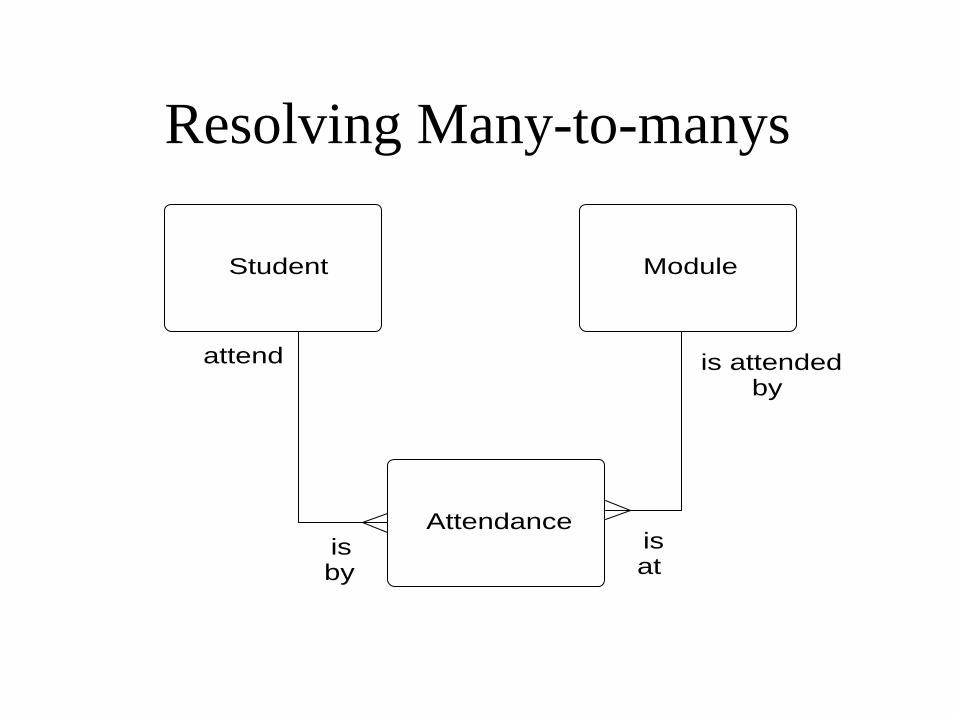
Resolving Many-to-manys
• Hide information• Difficult to physical represent
Student Moduleattend
is attendedby
Resolving Many-to-manys
Student Module
Attendance
attend
isby
isat
is attendedby

Optionality
• Optional - relationship MAY hold• Mandatory - relationship MUST hold• Two directions
Teacher Module_
taughtby
teach

Components of ER Diagram
• Entities with lists of attributes• Occurrences as set of values• Relationships
– two directions - two sentences– degree– optionality

Building ER Models
• Based entirely on requirements• Process must be repeated several times• Alternative to normalisation
Steps to ER modelling
• Identify entities• List attributes• Identify relationships• Repeat several times
Identify Entities
• One or two obvious ones• Use nouns in case study
– entity or attribute• Not the whole system!

List Attributes
• Again obvious ones for some entities• Use nouns in case study
– complex attributes might be entities• Use imagination
– for deliveries need addresses– for phone calls need phone numbers
Identify Relationships
• Consider each pair of entities• Begin drawing• Consider degree• Consider optionality• Resolve many-to-manys
Repeat
• Is there enough data to do the job?• Identify new entities and attributes• Fit them to existing model• Do it again!
Representing Relationships
• Each entity needs a primary key• Use a foreign key for many-to-one• The “many” entity has a foreign key
attribute• One-to-ones are rare or incorrect!
Validation
• Is there any repetition of data or relationships?
• Are all attributes and entities relevant?• Are all many-to-manys resolved?• Are the one-to-one relationships sensible?

The Data-Dictionary
• Description of ALL information on EVERY item of data
• Precisely defines the diagrams• Adds new detail• Backbone uniting all diagrams

ERD and Dictionary
• Description of every entity• Lists of attributes & descriptions• Volumetrics• Description of relationships
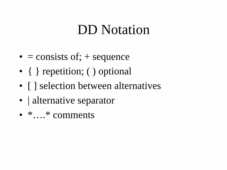
DD Notation
• = consists of; + sequence • { } repetition; ( ) optional• [ ] selection between alternatives• | alternative separator• *….* comments
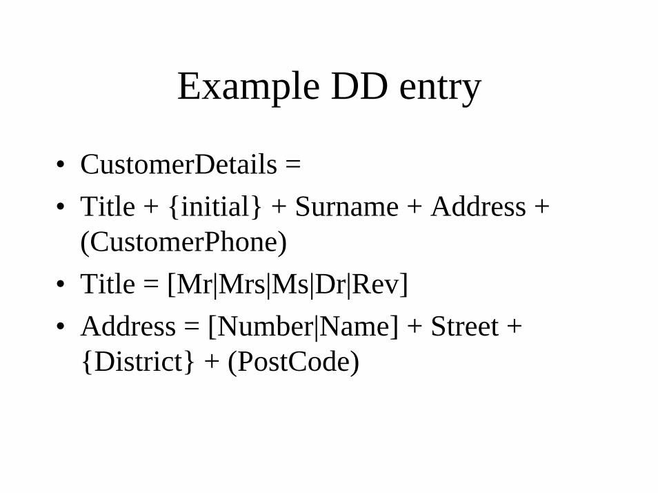
Example DD entry
• CustomerDetails = • Title + {initial} + Surname + Address +
(CustomerPhone)• Title = [Mr|Mrs|Ms|Dr|Rev]• Address = [Number|Name] + Street +
{District} + (PostCode)
Data-flow Diagrams
• Clarify requirements• Represent processes• Interaction between processes• Non-technical yet formal

Focus in DF diagrams
• Data input to the system• Data output from the system• Movement of data between processes• Storage of data within system• Top-down decomposition

External Entities
• Provides inputs, receives outputs• Different from Logical Data Structure• Represent types of things
Customer Customer
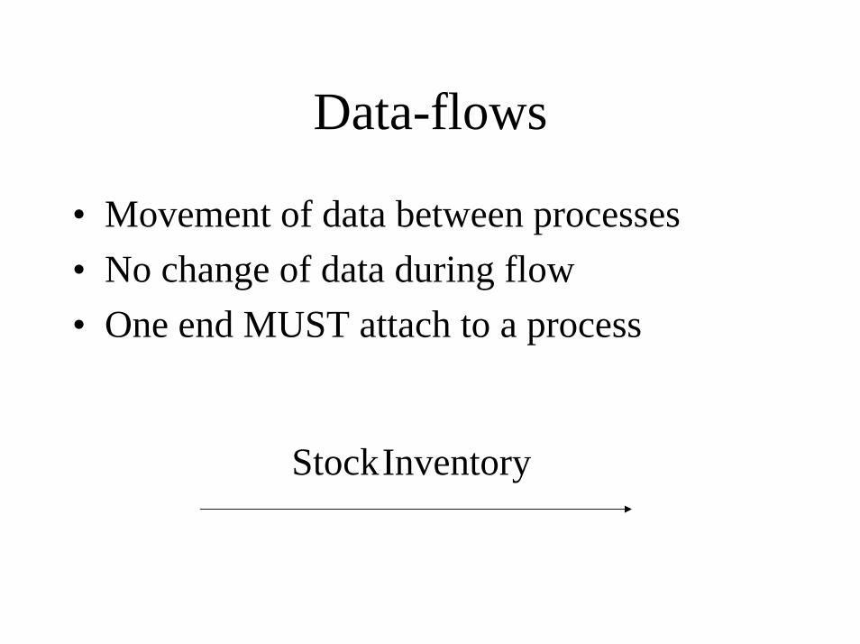
Data-flows
• Movement of data between processes• No change of data during flow• One end MUST attach to a process
StockInventory

Processes
• Main feature of DF diagrams• Change data• Appear as boxes:
*
Do somethingto something
Location4

Data stores
• Where data is stored inside the system• Named by what they store• “Read” does not mean “Delete”
CustomerDetailsD3 Customer
DetailsD3
Components of DF Diagrams
• Processes change data• Data flows between processes• External entities interact from outside• Data stores hold data internally
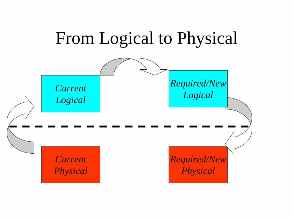
From Logical to Physical
CurrentPhysical
Required/NewPhysical
CurrentLogical
Required/NewLogical

Building DF diagrams
• Identify system boundaries• Begin construction
– Follow inputs– Follow events
• Fill in gaps• Repeat
Identify System Boundaries
• Identify external entities• Identify their inputs and outputs• Entities stand for types
Follow Inputs
• Start with important external entity• Make a process to receive its input• Define the process• Determine outputs of the process• Follow the outputs...

Follow Events
• Happenings in the case study– Either inputs or temporal events
• Make a process for the event• Identify inputs and outputs• Backtrack inputs or follow outputs
Fill in Gaps
• Is there enough data for each process to work?
• Where necessary add new inputs and backtrack
• Have all outputs been produced?• Check data store usage

Repeat
• Look for omitted functionality• Add new processes where necessary• Only finished when every word is either
included or deliberately omitted!

Levelling
• Levels help to simplify huge systems• Context diagram - level 0• Level 1 - system overview• Successive levels expand a process of the
previous level

Levels of Data Flow Diagram1
1.1 1.2 1.3
1.3.1 1.3.2
decomposes into
decomposes into a.
a.
a.
Features of Levelling
• Diagrams must balance• Numbering indicates the level• Bottom level is the process description
– flowcharts, English and structured English
Making Levels
• Start with context diagram• Expand complicated processes• Simplify diagrams by grouping• Balance

Validation of DF Diagrams I
• Is every DF attached to a process?• Does every process have an input and an
output• Are names sensible?• Do data-flows cross?

Validation of DF Diagrams II
• Do all diagrams balance?• Are all external entities on context diagram
and level 1?• Are all processes and data stores numbered
correctly?
DFD and Dictionary
• Description of data-flows• Description of external entities• Description of data stores• Description of process
Process Description
• Explains bottom level processes• Removes ambiguities
– Structured English– Formal English– Pseudocode
LDS and DFD
• LDS represents data stored• Data stores are where data is stored• Each data stores is made up of one or more
entities• Recorded in data dictionary
Data-flows and Attributes
• Data flows to a data store add data to entities
• Data flows from a data store take data from entities
• Data flows are made up of attributes or data items
Entity Life-Histories
• Design technique• Introduce time into the models• Represent ordering of events• Fill in holes in analysis

What are events?
• Events affect entities– change the values of data
• Look for writes to data stores• Inputs or temporal events• Events happen at a definite point in time

Extracting Events
• Verbs and verb-phrases• Make a list of candidate events• Decide what entities are affected • Work out which attributes change

Ordering Events
• One thing follows another - SEQUENCE• Either one thing or another happens -
OPTION• Something happens many times -
ITERATION

Other Orderings?
• Sequence, options and iteration are all that computers can do
• Other orderings are not necessary• Other orderings give simplicity• Describe them as we need them

Tree Structure
• Root is the entity itself• Branches have nodes• Leaves are the events• Parents, children and siblings
Leaves
• Represent events• Three types:
– creation– deletion/destruction– modification
• Events affect attributes

Nodes
• Represent:– sequences, [blank]– iterations, *– options, O
• Do not mix types of nodes!• Iteration is always an only child.
Special Structures
• Quit and Resume– quit from anywhere
• Parallel Structures• Null events

Reading ELH’s
• Read left to right– Creation on left– Death on right
• Children explain how to do parent• Quit - read the box and then jump
Components of ELH
• Root is the entity• Leaves are events• Nodes indicate ordering:
– sequence, iteration, optionality

Building ELH’s
• Identify events• Classify events
– creation, deletion, modification• Order the events• Repeat and innovate

Identify Events
• In data-flow model• From inputs and temporal events• Happenings in case study
Classify Events
• Creation, deletion, modification• Entity-event matrix• Modification events affect attributes
Order Events
• Creation events on the left• Deletion events on the right• Order events using different types of node• Use special structures if necessary

Repeat and Innovate
• Review case study– look for creation and deletion events
• Define sensible modification events• Match business practices

Validation
• Are there a root entity, a creation event and a deletion event?
• Do modification events modify?• Are the nodes correctly arranged?• Are quit and resume correctly labelled?

ELH and Dictionary
• Description of events• Attributes effected by events• Entity-event matrix

Models
• Models are simplified representations• Real or conceptual. • Suppress some aspects• Emphasize others
Models in systems development
• Impossible to use a single model• Hence a variety of models.• Every models specialises in some aspect of
the system.
Three Views of the System• Logical Data Models (LDM)
– WHAT is stored and how it is inter-related• Data Flow Models (DFD)
– how information is PASSED AROUND• Entity Life Histories (ELH)
– how information is CHANGED
Relationship between the Three Views
• Three models are related a defined way• Cross-checking for completeness and
consistency• Intelligent tools could produce‘first drafts’
from other models!
ER Diagram v. DF Diagram
• A data store corresponds to one or more entities
• Each entity is in some data store• Data flows to and from a data store are
composed of attributes• Exceptions: Transient data

ER Diagram v. ELH
• Each entity has a creation and deletion event
• Modification events affect attributes including foreign keys
• Each attribute is given a value• EEM relates all events and entities
DF Diagram v. ELH
• Events are inputs or temporal events• Events eventually cause input to data stores• One event may cause more than one such
input

(LDS)Entity
DataStore
Attributes
Dataflow
Event
writeto
writtento
madeup of
storedin
belongto
have
flow because
instigate
Data Dictionary
• Data about data– Data elements and data structures– Data-flows– Data-stores– Entity descriptions
• CASE tools
Methodologies
• What is a methodology?• Why use a methodology?• Which methodology?
What is a methodology?
• Integrates tools and techniques• Usually an underlying philosophy• Justified by experience• A methodology may or may not prescribe a
Life Cycle Model.
Methodology is not a LCM
• A LCM specifies and orders the development activities
• A methodology offers the tools• Although most methodologies specify a
LCM, some don’t.
Why Use a Methodology?
• Distilled experience/best practice• Ensures user involvement• Helps inexperienced analysts• Provides planning and control
Which Methodology?
• SSADM– data driven, highly prescriptive
• Yourdon– freer, emphasis on DFD, real-time aspects
• OO and incremental methodologies• SDLC is central to all
SSADM
• Open - developed by UK government• Mature• Waterfall fitting with standard life-cycle• User involvement
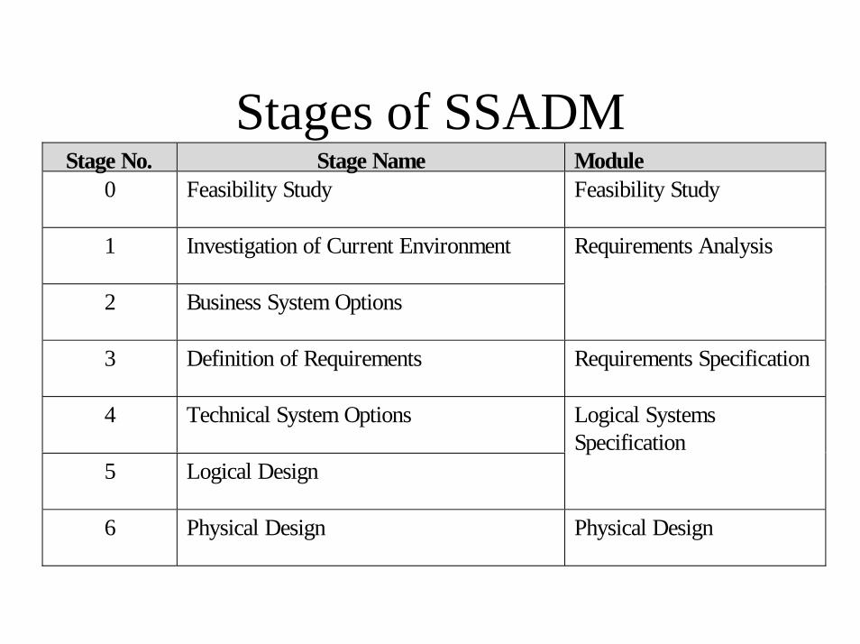
Stages of SSADMStage No. Stage Name Module
0 Feasibility Study Feasibility Study
1 Investigation of Current Environment
2 Business System Options
Requirements Analysis
3 Definition of Requirements Requirements Specification
4 Technical System Options
5 Logical Design
Logical SystemsSpecification
6 Physical Design Physical Design
Feasibility Study
• Technical - is it possible?• Financial - is it affordable?• Organisational - is it compatible?• Ethical - is it socially acceptable?
Investigation of the Current Environment
• Analyst learns business• Old system is core of the new system• Data model is built• Users are involved• System boundaries are defined
Products of Stage 1
• User Catalogue• Requirements Catalogue• Current Services Description
• Current environment logical data structure• Context diagram• Levelled set of DFD’s (current logical)• Data dictionary

Business System Options
• Brainstorming of ideas– degree of automation– boundary and distribution of system– cost v. benefit– impact
• Product is a single selected option

Requirements Specification
• Full specification inside framework of the business option
• Must match requirements• Must be free from error and ambiguity• All three models are employed and others

Products of Stage 3
• Data Dictionary• Requirements Catalogue• Processing Specification
• user/role function matrix• function definitions• models (required LDM, ELH, ECD)
Technical System Options
• Second brainstorming stage– hardware and software– cost of implementation– staffing and other physical considerations– format of human-computer interface
• Product is a single selected option
Logical Design
• Detailed design of human computer interface
• User dialogues• Update processes• Enquiry processes

Physical Design
• Huge and technical!• All design converted to detailed physical
implementation plan• Optimised for size and performance

Advantages of SSADM
• Three different views• Mature• Separation of logical and physical• Well-defined techniques • User involvement
Disadvantages of SSADM
• Large investment in training• User involvement• Difficult to change requirements• No short-term benefits• Incomplete life-cycle coverage