westt.orgwestt.org/pdfs/westt_2006_web.pdf · western regional trenchless review 2006 5 published...
TRANSCRIPT


Western Regional Trenchless Review 2006 5
Published by:
Del Communications Inc.211 Hespeler AvenueWinnipeg, ManitobaCanada R2L 0L5Fax: (204) 668-4641
PresidentDavid LangstaffToll Free: [email protected]
PublisherJason StefanikToll Free: [email protected]
EditorPaddy O’Toole
Advertising SalesGary BarringtonRoss JamesGladwyn NickelArlene NowickiMichael NurseDayna Oulion
Production services provided by:S.G. Bennett Marketing ServicesUnit 7, 414 Westmount DriveWinnipeg, Manitoba R2J 1P2Tel: (204) 895-2222www.sgbennett.com
Layout & DesignKathy Cable
Advertising ArtDebbie DunmallKelly Polanski
© Copyright 2006,Del Communications Inc.All rights reserved.The contents of this publication may notbe reproduced by any means, in whole orin part, without prior written consent ofthe publisher.
While every effort has been made to ensure theaccuracy of the information contained in andthe reliability of the source, the publisher in noway guarantees nor warrants the informationand is not responsible for errors, omissions orstatements made by advertisers. Opinions andrecommendations made by contributors oradvertisers are not necessarily those of the pub-lisher, its directors, officers or employees.
Publications mail agreement #40934510Return undeliverableCanadian addresses to:Del Communications Inc.211 Hespeler AvenueWinnipeg, ManitobaCanada R2L 0L5Email: [email protected]
PRINTED IN CANADA
DELCommunications Inc.
W E S T T 2 0 0 6
IN THIS ISSUE2006-2007 Calendar of Events ................................................................................................6Message from the WESTT Chairman ~ Dr. Samuel T. Ariaratnam ..................................8Message from the NASTT Executive Director ~ John Hemphill ....................................10The American Fiberglass CIPP Revolution ........................................................................12It Pays to be a NASTT Member! ...........................................................................................15Unparalleled Trenchless Education & Training................................................................16WESTT Board of Directors ....................................................................................................17No-Dig 2007 Preview / April 15-20, 2007Town and Country Resort, San Diego, California............................................................18Secondary Sewer Renewal Program (SSRP)An Innovative Approach to an Age Old Problem ............................................................20Geotechnical Engineering for Trenchless Projects..........................................................22Renovation of City of Santa Monica’s Earthquake Damaged Sewers..........................26Open-Cut vs. Trenchless TechnologyBursting Tradition at the Bagley Industrial Park.............................................................28The Genesis of a Condition Based Asset Management Program forCritical Water Pipelines .........................................................................................................31Unique Trenchless Solutions for Sewers in Southern California .................................36Product Pipe Material for Pipe Bursting ............................................................................40Rain for Rent Completes Temple Town Lake85 MGC Sewer Rehabilitation Project ................................................................................44Years Measured in Feats:20 Years of Trenchless Project Innovations.......................................................................47Sauereisen Advances Anti-Corrosion Technology...........................................................48Specialized Services CompanyA Case for S.U.E. .....................................................................................................................50Go Trenchless, Young Man — And Bring PVC Pipe ........................................................52Waterline Rehabilitation — Pipe Bursting, Trend of the Future ..................................55An Innovative Approach to Varied Locating ChallengesThe DigiTrak Eclipse Locating System................................................................................57Pacific Multilining Acquires New CIPP Lining System ....................................................60Pipe Genie — New Pulling Cones Save Time & Money ...................................................61Index to Advertisers ..............................................................................................................63

6 Western Regional Trenchless Review 2006
EVENTS
2006-07 CALENDAR OF EVENTS
Twenty Years Of Proven Protection
The Raven Advantage
Raven® and AquataPoxy® coatings provide the safest,lasting solutions for protection and rehabilitation of:
• Manholes • Headworks • Clarifiers • Lift Stations • Pipes & Tunnels • Tanks & Basins
Proven coating solutions for wastewater infrastructure,Raven systems offer the best chemical resistance andstructural properties available. Tenacious bonding tounderground infrastructure makes Raven the rightchoice for long-term service in collection system andtreatment plant structures.
Engineered solutions include a nationwide networkof Certified Applicators using state-of-the-artapplication technology for quality installations.
Take advantage of our twenty years of proven success ... specify and use Raven on your nextproject.
800-324-2810www.ravenlining.com
2006 Raven Lining SystemsFor a lifetime of protection.
September 200610-13—APWA International Public Works Congress
& Exposition, New Orleans, LA18-19—NASTT Horizontal Directional Drilling Good
Practices Course, East Gwillimbury, Ontario23-29—IPLOCA Convention 2006, Barcelona, Spain27-30 —ASCE Annual Conference & Exposition,
Chicago, IL 25-29—2006 International Pipeline Conference
& Exposition, Calgary, Alberta26-28—No-Dig Live 2006, Stoneleigh Park,
Coventry, United Kingdom
October 20062-5—FTTH Council 2006 FTTH Conference & Expo,
Las Vegas, NV21-25—WEFTEC 2006 Annual Conference & Expo,
Dallas, TX26-27—8th International Trenchless Technology Research
Colloquium, Sydney, Australia29-Nov. 2—2006 International No-Dig Conference,
Brisbane, Australia
November 20066-7—2nd Annual Western Regional No-Dig Conference
& Exposition, Walnut Creek, CA5-7—AEM Annual Conference, Boca Raton, FL14—NASTT Laterals Good Practices Course,
Edmonton, Alberta
15—2006 Alberta Trenchless Technology Symposium,Edmonton, Alberta
21-22 —BAUMA-China 2006, Shanghai, China
December 20065—NASTT Horizontal Directional Drilling Good
Practices Course, Phoenix, AZ6-7—2006 Damage Prevention Conference & Expo,
Phoenix, AZ
January 200721-25 —DCA’s 46th Annual Convention,
Paradise Island, Bahamas22-26—World of Concrete 2007, Las Vegas, NV30-Feb. 1—2007 Underground Construction Technology
International Conference & Exposition
February 20077-10—2007 Pumper and Cleaner Environmental Expo
International, Nashville, TN11-14 —NUCA Utility Construction EXPO’07,
Las Vegas, NV18-21—ASCE Geo-Denver 2007, Denver, CO21-25—Pipe Line Contractors Association Annual
Conference, Aventura, FL
March 20076-8—2007 CGA Excavation Safety Conference & Expo,
Orlando, FL21-25 —2007 AGC Annual Convention, San Antonio, TX
April 200715-20—No-Dig 2007 Conference & Exhibition,
San Diego, CA18-19—NASTT Pipe Bursting Good Practices Course,
San Diego, CA18-19—NASTT Lateral Rehabilitation & Replacement
Good Practices Course, San Diego, CA18-19—ISTT Pressure Pipe Design Course, San Diego, CA19-20—NASSCO Pipeline Assessment Certification
Program, San Diego, CA23-29—BAUMA 2007, Munich, Germany
May 20075-10—World Tunnel Congress and ITA General Assembly,
Prague, Czech Republic6-8—2007 ASCE Construction Research Congress,
Grand Bahama Island, Bahamas
June 20076-9—CSCE Annual General Meeting and Conference,
Yellowknife, Northwest Territories10-13—Rapid Excavation and Tunneling Conference
RETC 2007, Toronto, Ontario17-21—AWWA Conference & Exposition, Toronto, Ont.
July 20078-11—ASCE International Pipeline Conference 2007,
Boston, MA

8 Western Regional Trenchless Review 2006
MESSAGEFROM THE WESTT CHAIRMAN
Dr. Samuel T. Ariaratnam
AS THE CURRENT CHAPTER CHAIR-man, I would like to personally invite youto read this inaugural issue of theWestern Trenchless Review. The WesternSociety for Trenchless Technology(WESTT) was formed in 2004 as a region-al chapter of the North American Societyfor Trenchless Technology (NASTT), cov-ering a four State region comprised ofArizona, California, Nevada, and NewMexico. WESTT has a volunteer Board ofDirectors, with representation from aca-demia, government, and industry cover-ing all four States.
Quoting directly from the by-laws, ourobjective is to “advance the science andpractice of Trenchless Technology for the
public benefit; to promote and conducteducation, training, study, and researchin said science and practice for the publicbenefit; and to make available informa-tion thereof to all interested and con-cerned parties.” WESTT aims to be asource of connecting individuals interest-ed in learning about adoption of varioustrenchless techniques as a viable solutionto their infrastructure needs. Sharing ofexperiences is an excellent way for evalu-ating the suitability of a particularmethod to your specific situation.
Our inaugural Chapter event was theFirst Annual Western Regional No-DigConference and Exhibition held onNovember 14-15, 2005 in Tempe, Ari-zona. The event attracted over 130 peo-ple and 21 sponsoring vendor companies.The opening keynote address, entitled“Tracking Down the Roots of OurSanitary Sewers” was delivered by notedhistorian Jon Schladweiler. Incidentally,Jon was featured in the July 27, 2005History Channel special on the “Historyof Sewers”.
There were a total of fifteen technicalpapers given by presenters, mainly fromthe four State region. The conference fea-tured a repetition of papers given at No-Dig 2005 in Orlando in May 2005. Thepeer-reviewed format ensured that onlypapers of high quality were presented. In
addition, the NASTT-developed, “PipeBursting Good Practices” course wasgiven by myself, and Dr. David Bennettfrom Bennett-Staheli Engineers, as apost-conference short-course. Attendedby 25 people, this course provided atten-dees with information on ways to engagein a successful pipe bursting projects.
The Second Annual Western RegionalNo-Dig Conference and Exhibition willbe held in mid-November in Sacramento,California. For further informationabout this event, please contact eitherJennifer Glynn at [email protected](925-627-4100) or myself. We anticipateanother informative program filled withtechnical content and vendor booths.Keeping with our philosophy, the presen-tations will be a repetition of peer-reviewed papers given at No-Dig 2006this past March in Nashville by WESTTmembers.
I look forward to another excellent yearfor trenchless activities in the Westernregion and welcome new members to jointhe Western Chapter. Please feel free tocontact me at [email protected] or(480) 965-7399 if you require any in-formation on WESTT or trenchless ingeneral.
Warmest regards, Dr. Samuel T. AriaratnamChairman, WESTT ❍
RALPH R. CARPENTERMARKETING SPECIALIST
1501 31st Avenue North • Birmingham, AL 35207Phone: 205/325-1965 • Fax: 205/307-2799
E-mail: [email protected] • www.acipco.com
American Flex-Ring Joint Pipe for Horizontal Directional Drilling
AMERICAN DUCTILE IRON PIPE
AMERICAN SPIRALWELD PIPE
TTRREENNCCHHLLEESSSS TTEECCHHNNOOLLOOGGYYworks well when it is done right.
Ensuring quality of the finished productmeans choosing the BBEESSTT PPRROOCCEESSSS,utilizing PPRROOPPEERR SSPPEECCIIFFIICCAATTIIOONNSS
and insuring the process isIINNSSTTAALLLLEEDD correctly. QA/QC
RAISING THE BAR of the trenchlessindustry for the past 2 decades.
Trenchless Resources InternationalTM
The Consultants’ CONSULTANT
PACP,Master Trainer


10 Western Regional Trenchless Review 2006
MESSAGEFROM THE NASTT EXECUTIVE DIRECTOR
John Hemphill
THE NORTH AMERICAN SOCIETYfor Trenchless Technology recently cele-brated its 15th No-Dig, which is not somuch a testimony to the longevity ofNASTT, but is more an affirmation of thevalidity and relevance of the Society’s edu-cation and training mission. Less noticed,but perhaps more significant to NASTTlong-term training strategy, was theWestern Chapter’s highly successful Mini-No-Dig held in Phoenix in November2005.
The WESTT Mini-No-Dig was its firstofficial organized event. As its name sug-
gests, the WESTT Mini No-Dig was ascaled-down version of the No-Dig Show.Focusing on issues of interest to peoplewho reside in western region of NorthAmerica, WESTT invited authors ofpapers presented at the 2005 No-Dig whowere also WESTT members to presenttheir papers again at the WESTT Mini-No-Dig.
The NASTT annual No-Dig technicalsessions are recognized for their highquality. The key is the selection and peerreview process employed by NASTT,which focuses on relevance and quality.The process is simple; get volunteers withexpertise in trenchless to ensure that thetechnical session content meets qualitystandards. Fortunately, NASTT has anumber of members who qualify asexperts and are willing to volunteer theirtime and effort for this purpose. Many ofthese volunteers are WESTT members,and again I thank you for your help.
Typically 1,400 to 1,500 individualsattend the NASTT annual No-Dig each
year, which, although impressive, does notbegin to include all who could benefitfrom attending No-Dig. The WESTTleadership came up with an innovativeconcept. Realizing that many Mini-No-Dig attendees were unable to attend the2005 No-Dig held in Orlando, or may nothave had heard these presentations whenat No-Dig, WESTT decided to provide asecond bite at the apple for its membersand others in the region. Hence, the Mini-No-Dig concept - it worked beautifully!
I saw first-hand the enthusiasm of theattendees. The WESTT leadership is to becongratulated for coming up with such aninnovative approach to fulfilling theSociety’s education mission. Clearly, theMini-No-Dig concept is a real winner andshould serve as a model for other chap-ters.
Again, congratulations and good luck!John Hemphill, Executive DirectorNorth American SocietyFor Trenchless Technology ❍
NASTT WESTERN CHAPTERINSTITUTES MODEL FORUM


PROFILE
Cured-in-Place-Pipe is a real solution forthe rehabilitation of sewer and drainagepipes that are rapidly deteriorating in theUnited States. The technology of CIPPhas brought with it a number of advan-tages that has made CIPP one of thefastest growing choices for pipe rehabili-tation in the world.
For the past 20 years, CIPP in the U. S.market has been done with felt based lin-ing solutions. These solutions haveenabled customers to avoid digging upand replacing ever-increasing amounts ofdamaged pipes, saving the American citi-zen hundreds of millions of dollars. Now,with the introduction of UV light curedfiberglass lining technology, the advan-tages of CIPP are about to take a quantumleap in providing the U.S. a longer lastingmore environmentally friendly solution.
Facts about FeltBefore we discuss this jump in technol-
ogy with UV cured fiberglass lining,(UVCFG), we need to understand the factsabout felt liners and their properties. FeltCIPP liners have the following characteris-tics:1) A maximum flexural strength of
300,000psi2) Are cured using hot water or steam3) Can utilize poly ester or vinyl ester resin
and epoxy resin4) The felt tube is “wet out” on the job
sight.5) The “wet out” felt is inverted into the
host pipe or in rare cases, pulledthrough.
6) Felt liners are in most cases bonded tothe host pipe
7) Have an ever increasing wall thicknessto ensure a 300,000psi flexuralstrength
8) Have been tested and certified to have a9% rate of leakage, (IKT report, 2005)
9) Have a 50% utilization rate in EuropeWith all of the advantages that felt lin-
ing has provided the marketplace, thereare some problems when using felt liningthat need to be considered:1) Air bubbles are common in the wetting
out process, which can cause leaks.2) The wetting out process in neighbor-
hood; release a variety of chemicals andtheir associated odors into the air, anenvironmental hazard for both work-ers and the neighborhood.
3) The curing process releases a variety ofchemicals into the sewer and drainagesystems which can end up in groundwater and fresh water systems.
4) The curing process for felt liners is heatsensitive, causing installation problemsin high temperature climates.
5) Felt liners have seams which can causeleaks.
6) Felt liners bond to the host pipe, whichrequires the host pipe to be in relativelygood condition to prevent gaps andmalformations in the final product.This increases the amount of spotrepairs before installation.
7) The installation process cannot bemonitored, therefore, you never knowhow well the job has been done until itis done.
8) The larger the wall thickness, the largerthe shrink of the liner after curingresulting in water infiltration overmanholes and lateral connection.
The UV Light, Fiberglass LeapFelt lining solutions in the U.S. have
been written into every specification forevery CIPP bid. Until recently, there hasbeen no alternative, and thousands ofmiles of rehab have been completed usingthis technology. The industry is now
THE AMERICANFIBERGLASSCIPP REVOLUTIONBy Richard “Monte” Montemarano, VP of Sales and Marketing, iPL Technologies, U.S., Inc.
12 Western Regional Trenchless Review 2006


PROFILE
poised to experience a very real and veryhigh quality alternative that has been test-ed, proven and now, achieved a writtenASTM standard for the inclusion in thebidding process: Ultra Violet Light CuredFiberglass.
To fully understand the advantages andimpact that UVCFG can provide to theAmerican marketplace, it is best to look atthis technology from a categorical pointof view.
The Environmental DifferenceFirst and foremost, UV light cured
fiberglass liner is total environmentallyfriendly. No water or steam is used, so nohazardous waste is released into the wateror air. There are no large and noisy piecesof equipment on the streets. Traffic is lessof an issue from the quick job installationtimes.
A Higher Quality ProductThe most impressive aspect of UVCFG
is the product itself. Compare these prop-erties to the properties of felt that werementioned previously:1) A maximum flexural strength of
1,700,000 psi2) Is cured using ultra violet light3) Can utilize poly ester or vinyl ester resin4) Liner is pre-manufactured under high-
ly monitored and tested specificationsand factory conditions, not at the jobsight.
5) Is pulled into the host pipe6) Is a stand alone pipe, at least as strong
as the original host pipe7) Has a thin wall thickness to ensure to
maximize flow8) Has been tested and certified to have a
0% rate of leakage, (IKT report, 2005)9) Is used for 50% of the European market
for CIPP.
The Installation AdvantageWith dramatic difference in product
quality come a remarkable difference inthe way the product is installed.
UVCFG has an inner and outer linerfoil. They hold the resin in place whichhas been procured to 10% at the factory.The outer foil is light proof and since theresin cures under light and not heat, theoutside temperature is not an issue forUVCFG.
The liner is pulled through the pipewith a winch and capped on both ends.The “gates” allow for the UV light cable tobe pulled by a computer monitoredprocess. Once the liner is in place, the UVlight chain inserted and the ends of theliner are capped, the liner is pressurized to7 psi. The UV light chain is equipped witha camera to inspect the liner installationBEFORE it is cured. When there is visualassurance of a quality fit, the lights are
turned on and the liner is cured at any-where from 5 to 10 feet per minute. Thecamera on the light chain monitors thecuring process.
The R.O.I.Overall, UVCFG is at least a 30% more
cost effective solution than felt. Althoughthe material is more expensive, the set-up,reduced amount of spot repairs and fastcuring times all reduce the total cost of ajob dramatically. Even if a bid for felt isthe same as UVCFG, the unstated reduc-tion in the cost of the job is less time forall of the peripheral services such asbypass pumping and traffic control. Inaddition to the great financial return oninvestment on UVCFG, it is not onlyneighborhood friendly because or re-duced noise and smell, but it is guaran-teed for 80 years! No other lining technol-ogy will give that warranty, if any at all.
With the higher quality, speed andlongevity of UVCFG, it is only a matter oftime before this technology becomes areal alternative to felt in the U.S. market-place.
For further information oniPL Technologies and their products,please call Richard “Monte”Montemarano, VP of Sales and Marketingat 858-909-0010x225 or e-mail [email protected].
❍
14 Western Regional Trenchless Review 2006

NASTT
It Pays to be a NASTT Member!NASTT is a not-for-profit, educationaland technical society that is dedicated topromoting the benefits of trenchless tech-nology for the public awareness througheducation and training. Founded in 1990,NASTT is the definitive resource fortrenchless professionals, like you, who areconcerned with underground systems andthe applications of trenchless technology.NASTT connects you to the people andbusinesses involved in the trenchlessindustry.
NASTT is your link to thousands oftrenchless professionals and leaders work-ing in regional, national, and internation-al levels. Membership is open to individu-als, agencies, and companies involvedwith providing gas, water, sewage, com-munications, and electrical services. Ifyou’re interested or involved in under-ground systems and the application oftrenchless technology, then NASTT mem-bership is right for you.
NASTT Members Receive:When you join NASTT, you automati-
cally become a member of your regionalchapter and a member of the Interna-tional Society for Trenchless Technology(ISTT).
Members-Only Discounts– Registration discounts to the annual
No-Dig Show and other NASTT train-ing programs (corporate membersreceive No-Dig exhibitor discounts)
– Discounted pricing on these NASTTpublications: No-Dig Conference Pro-ceedings, Horizontal Directional Drill-ing Guidelines, ISTT Trenchless Tech-nology Guidelines and Pipe BurstingGood Practices Manual
Industry Publications & Reference Tools– A subscription to Trenchless Techno-
logy, a monthly publication– The Annual Directory of the North
American Trenchless Technology In-dustry and The International Society forTrenchless Technology (ISTT) Yearbook& Directory
– Quarterly NASTT newsletter to keepyou updated and informed
– Members-only access to technical paperspresented at the No-Dig Show
Leadership Opportunities– Participation in committee work– Involvement in your regional chapter– Opportunity to serve on the No-Dig
Program Committee
Become an NASTT member today!Call 703-217-1382,
e-mail [email protected] or visitwww.nastt.org
❍
CLOSE DOESN’TCOUNT.
When Millimeters Matter, AkkermanGBMs Provide Pinpoint Accuracy.
Designed for easy operation, Akkerman GuidedBoring Machines (GBM) utilize video surveillance of illuminated targets to assure the exacting lineand grade tolerances needed for the gravity sewer and water industry. Available in single stage orlatching frame configurations, Akkerman GBMs are ideal for auger boring contractors looking for a higher standard in accuracy.
To hit the mark on your next boring or pipejacking project, choose Akkerman.
58256 266th Street \ Brownsdale, MN 55918 \ USA
507.567.2261 \ 1.800.533.0386 \ fax 507.567.2605
www.akkerman.com \ email: [email protected]
Western Regional Trenchless Review 2006 15

16 Western Regional Trenchless Review 2006
NASTT
NASTT delivers top-notch training courses to trenchless profes-sionals. Whether you’re experienced or a newcomer to the indus-try, you can hone your knowledge and skills through one ofNASTT’s training courses.
By attending NASTT training programs, you are guaranteed: – A comprehensive, consensus-based course outline– Non-commercial, academically-oriented presentations– Expert instructors in their respective fields– CEUs/PDHs offered for your participation– Networking opportunities to connect you with the people
and businesses involved in the trenchless industry
NASTT Education & Training Programs offered:– Annual No-Dig Conference & Exhibition– Cured-In-Place-Pipe Good Practices– HDD Good Practices Guidelines– Lateral Rehabilitation & Replacement Good Practices– Pipe Bursting Good Practices– Trenchless Technology Overview
Visit www.nastt.org for a complete training schedule.❍
Unparalleled TrenchlessEDUCATION & TRAINING
Looking for the industries premium quality
Forged one-piece drill pipe for your
Navigator®, Jettrak® machine or other
Directional Drills?
Call today to order a few
pieces or a whole bundle!
1-888-427-0379Visit Us: CarsonUnderground.
CARSON
UNDERGROUND, INC.
1-800-850-3043
FORRENT
Pipe Bursting
EquipmentPipe Bursting
Equipment

Western Regional Trenchless Review 2006 17
WESTT
Dr. Samuel Ariaratnam, ChairmanAcademiaArizona State UniversityTempe, [email protected]
Paul Reilly, TreasurerManufacturers/SuppliersRain for RentBakersfield, [email protected]
John Boehm, SecretaryConsultantsHolmes InternationalSacramento, [email protected]
Ron Ablin, DirectorConsultantsBrown and CaldwellPhoenix, [email protected]
Craig Camp, DirectorConsultantsJacobs AssociatesSan Diego, [email protected]
Eugenia Chusid, DirectorOwnersCity of Santa MonicaSanta Monica, [email protected]
Jennifer Glynn, DirectorConsultantsRMC Water and EnvironmentWalnut Creek, [email protected]
Dave Mathy, DirectorConsultantsDCM EngineeringWalnut Creek, [email protected]
Michael Rocco, DirectorContractorsAUI IncorporatedAlbuquerque, [email protected]
Mike StramOwnersCity of RenoReno, [email protected] ❍
Western Society of Trenchless TechnologyBOARD of DIRECTORS

18 Western Regional Trenchless Review 2006
CONFERENCE
No-Dig 2006 was held from March 26-31 at the Opryland Hotel inNashville, Tennessee, and the event attracted over 1,400 attendeesto the conference and exhibition. This was the 15th anniversary ofthe inaugural event, held in 1991. There were over 90 peer-reviewed technical paper presentations, spanning all aspects oftrenchless construction. Three post-conference seminars weredelivered including: 1) Lateral Rehabilitation & ReplacementGood Practices; 2) HDD Good Practices; and 3) NASSCO PipelineAssessment Certification Program (PACP). A pre-conference sem-inar on “Introduction to Trenchless 101 - New Construction &Rehabilitation” was held for those individuals new to the tech-nologies who wanted to gain a better understanding prior toattending the technical sessions. The 5th Educational FundAuction & Reception raised over $40,000 for educational activities,including student support. The Gala Awards Dinner & Receptionfeatured a performed by the Cirque Odyssey troupe, which thor-oughly entertained the sold-out audience.
No-Dig 2007 will be held at the Town & Country Resort andConvention Center in San Diego, California, with the theme being“Riding the Wave of Trenchless Technology”. The ConferenceProgram Committee received a record 182 abstracts, of which 112were selected for presentation. In keeping with recent tradition, allof these papers will go through a rigorous peer-review process toensure technical merit prior to publication in the conference pro-ceedings.
We are pleased to have the National TelecommunicationsDamage Prevention Council (NTDPC) sponsoring a special ses-sion on “Underground Damage Prevention”. This is an importanttopic when dealing with trenchless projects. Due to San Diego’s
close proximity to Mexico and its high Spanish-speaking popula-tion, the conference will offer a special Spanish-only course on“Introduction to Trenchless Technologies” on the morning of July16. It is anticipated that this course will attract interested individ-uals from Mexico and other Spanish-speaking countries. Thisyear’s goal is to attract over 2,000 attendees, and raise over $50,000at the 6th Annual Educational Fund Auction. These are high tar-get goals; however I am confident that those who attend this year’sevent will enjoy the high-quality technical paper presentations,informative vendor exhibits, and social interactions. Be sure tovisit www.nastt.org for updated conference information.
Highlights of theevent will include:
– 8th Annual No-Dig Golf Classicat the RiverwalkGolf Club
– NASTT’s 6thAnnualEducationalFund Auction& Reception
– Gala AwardsDinner &Reception fea-turing someexcellententertain-ment for theevening
– Pre- andPost-confer-ence short-coursesI encourage you to attend this 16th Annual No-Dig event, and
bring along the family for an excellent adventure in sunny, pic-turesque San Diego!
Warmest wishes,Dr. Samuel T. AriaratnamArizona State University2007 No-Dig Show Program Chair ❍
NO-DIG 2007 PREVIEWTown and Country ResortSan Diego, CaliforniaApril 15-20, 2007

If your goal is to maximize safe excavation productivity with minimal liability, the solutionis clear. The HXX from Vactor. The HXX enables you to eliminate damage to linescaused by hand or mechanical digging, avoid personal injury and minimize landscaperepair using only water and a vacuum. In addition, HXX’s hydro-excavation design letsyou work in remote locations where mechanical excavation isn’t possible. Designed for the contractor, the HXX is now available with standard fan or PD option. The HXX.The most flexible, easy-to-operate hydro-excavator manufactured today. For moreinformation, call 800-627-3171. Or visit www.vactor.com.
© 2005 Federal Signal Corporation. Federal Signal Corporation is listed on the NYSE by the symbol FSS.
www.vactor.com

LOS ANGELES, CA
I. HistoryThe City of Los Angeles (the City) operates and maintains morethan 6,500 miles of sewers that serve more than four million peo-ple.
In October 2004 the City entered into a settlement agreementwhich, among other requirements, stipulates that the City mustcontinue its current $2-billion, 10-year sewer renewal program,and enhance its efforts by increasing the lengths of sewers beingrenewed to an average of 60 miles per year. In order to meet therequirements and deliver the increased number of projects in a
timely manner, the Secondary Sewer Renewal Program (SSRP),more commonly referred to as the 60-Mile Program, was created.This program is dedicated to planning, design, and constructionof some of the Settlement Agreement Projects (SAP).
II. ProtocolA protocol has been set up to expedite the delivery of these proj-
ects. As part of this process, the City has been subdivided intomore than 210 sewersheds (see Figure 1). Based on the mainte-nance records and history of sanitary sewer overflows (SSO), thesheds are prioritized and the sewers are televised to documenttheir condition. Based on the condition report, City engineersprepare the pre-design report, design documents, process theproject through bid and award, and manage the construction. Anaverage of 25 projects per year are planned.
III. DesignGiven the increased workload of the 60-Mile Program, the
Bureau of Engineering (BOE) created a standardized documentfor design where all viable rehabilitation methods and materialsare detailed (for instance, the rehabilitation methods and the lin-ers are all listed). This protocol/ method works very well with theSSRP program, because the program deals with small sewersexclusively (6 inch to 15 inch sewers).
The design itself also conforms to a very well defined regimen.First, the defects are categorized into root intrusion/blockage orvarious structural defects. Peripheral issues are also studied;among them hydraulic adequacy and appurtenant structures (e.g.addition of maintenance hole for maintenance access improve-ment). Then the appropriate rehabilitation method is assigned.Three rehabilitation methods are feasible: remove and replace, lin-ing, or a combination thereof. The lining can be any of the City’sapproved materials, structural or nonstructural. When there ismore than one option to repair a reach, a quick cost benefit analy-sis is performed to find the most economical solution. Additionalfactors, such as traffic conditions, will also have impacts on theselection of rehabilitation methods.
IV. Computer Applications (Customized Design Tool)BOE contracted the services of MARRS Services Inc, a consult-
ing firm from Santa Fe Springs, California, to develop a GIS-based desktop application for further streamlining the design.
SECONDARY SEWER RENEWAL PROGRAM (SSRP)Wastewater Conveyance Engineering Division, Bureau of Engineering, City of Los Angeles
AN INNOVATIVE APPROACHTO AN AGE OLD PROBLEMby David Ouyang, Mina Azarnia, Richard Carbajal, Hong Chen, Thomas Enriquez,
Christine Keushguerian, Mohammad Seyedroudbari, Karla Shahin
FIGURE 1
20 Western Regional Trenchless Review 2006

This application, Sewer ManagementAutomated Renewal Tracking System(SMARTS©), centralizes and integrates avast amount of spatial and non-spatialinformation such as sewer systems, sub-structure utilities, parcels, aerial photo-graphs, and digital pipe assessment andvisualizes the locations and other impor-tant characteristics of damaged pipes (seeFigure 2). By utilizing ArcObjects anddatabase technology, SMARTS© applica-tion provides customized features to helpengineers quickly identify factors relatingto sewer repair and allows them to com-plete design more efficiently.
Inherent to the designs are several rep-etitious calculation requirements, genera-tion of tables, extensive research, anddevelopment of vicinity maps as well askey maps (Figure 3). This is where
SMARTS© comes through with a rigor-ous software to change the traditionalway of completing a design. Time neededto perform these tasks is significantlyreduced. For instance, several tasks, tradi-tionally performed in sequential order,such as utility investigation and lookingat aerial maps etc. can be performedsimultaneously. This is enabled by thesoftware that shows information on sev-eral processes on the same screen (Figure4). Also, instead of inputting the tradi-tional data to complete a design, it isautomated by SMARTS© based on pre-design reports and the engineers’ work.SMARTS© facilitates the preparation ofdesign packages. The final bid docu-ments generated from SMARTS© are notthe typical plans and profiles, but a tabu-lar list of pipe reaches and a specific reha-
bilitation/replacement method specifiedcombined with the City’s WastewaterMaster Specifications. Again, this soft-ware is evolving as the SSRP programprogresses. The SMARTS© program isexpected to fully mature during the nextyear. Numerous quality assurance andquality control (QA/QC) procedures havebeen implemented to allow rapid identifi-cation of errors.
V. Results This innovative and streamlined ap-proach to design has yielded a substantialincrease in productivity. It is estimatedthat a typical pre-design report will becompleted in four months and the com-pletion of the design can be achieved infour to six months.
VI. CostOnce the engineer finishes the design of aproject, he/she prepares a more detailedCity Engineer’s estimate. Typically, stan-dard unit costs are used to prepare thisestimate for removal and replacement,for lining, and for different beddingmaterial or encasement. The SSRP pro-gram is entirely funded by the City; it willbe paid for by the sewer service charge. NoFederal or State assistance is involved.
VII. Duration The Settlement Agreement is in effectuntil the end of fiscal year 2013/2014,but the protocols established for SSRPare expected to be used beyond that.
❍
LOS ANGELES, CA
FIGURE 2
FIGURE 4
Western Regional Trenchless Review 2006 21
FIGURE 3

GEOTECHNICAL
Success in trenchless pipeline design and construction depends onthe combined experience and contributions of owners, engineersand contractors. A thorough and complete geotechnical engineer-ing investigation specifically addressing the proposed method oftrenchless installation is a key component to this success. In fact,the level of importance placed on the geotechnical engineeringinvestigation for a trenchless project by both designers and con-tractors is significantly greater than that for conventional open-cuttrenching. As a result, the expectations of experienced owners,designers and contractors are higher and the scope and detail of thegeotechnical investigation is greater (i.e. the geotechnical bar is atits highest for trenchless design and construction). From the geot-echnical engineer’s point of view, the most significant challenge ontrenchless projects is that of completely understanding and appre-ciating the capabilities and limitations of various old, evolving, andemerging trenchless technologies and relating subsurface condi-tions to those technologies. This requires experience, judgmentand specific effort on the part of the geotechnical engineer to keep
up with trenchless literature and trenchless construction case his-tories (i.e. trenchless construction precedent).
Geotechnical conditions influence all surface and undergroundconstruction. The influence of geotechnical conditions is signifi-cantly greater for pipelines potentially involving thousands of feetof continuous excavation than for buildings involving localizedexcavations within relatively small footprint areas. An understand-ing of geologic setting, and the geologic process as they determinegeotechnical conditions, provides a framework upon which tocharacterize the range of subsurface conditions along a proposedpipeline alignment, including changing soil and soil properties,changes from soil to bedrock, changing bedrock and bedrock prop-erties and changing groundwater conditions. Traditional methodsof open-cut pipeline construction are somewhat forgiving in exca-vating through variable subsurface conditions. Trenchless meth-ods of construction are far more complex than open-cut trenchingand as a result are much more sensitive (and less forgiving) to sub-surface conditions and variations in subsurface conditions along apipeline alignment. In fact, there are certain combinations of sub-surface conditions where trenchless methods may not be feasible(e.g., small diameter microtunnel pipe jacking through cobbles andboulders which are too large for a microtunnel boring machine toingest and crush, or through fills with oversize debris, metal, woodor other man-made obstructions).
Many design engineers and most owners arrive at trenchless tech-nologies through the pipeline utility industry and conventionalopen-cut installation of buried utilities. As a result, some designersand owners still allow or even specify geotechnical investigationswhich are typical for open-cut pipeline design and construction,rather than the more rigorous geotechnical investigations requiredfor trenchless design and construction. While trenchless projectsmay involve some aspects of open-cut methods (e.g. shaft and pitshoring and dewatering), the geotechnical engineering investiga-
Geotechnical Engineering forTrenchless Projectsby David C. Mathy, DCM Engineering
22 Western Regional Trenchless Review 2006
Photo Group 1: Geotechnical engineering for trenchless projects.

Western Regional Trenchless Review 2006 23
GEOTECHNICAL
tion should be specifically approached as trenchless design; not asopen-cut trenching. Table Nos. 1 and 2 are qualitative comparisonsof the principal geologic and geotechnical factors that influenceopen-cut trenching pipeline design and construction and trench-less pipeline design and construction. As illustrated in Tables 1 and2, trenchless methods are far more sensitive to many more subsur-face conditions than open-cut trenching. In addition to typicalgeotechnical engineering properties and analysis for open cuttrenching, a trenchless geotechnical engineering investigation mayhave to address any one of many unique soil and bedrock propertiesand impacts on trenchless construction, such as:– Tunnelman’s Ground Classification (Terzaghi, 1950, Heuer,
1974);– Cobbles and boulders, size and distribution;– Cobbles and boulders, unconfined compressive strength;– Man-made obstructions, fills and fill composition;– Tunnel overcut stability and systemic settlement;– Tunnel face stability;– Clay and claystone swelling;– Bedrock abrasiveness;– Bedrock fracturing, faulting and jointing;– Bedrock slake/durability;– Bedrock strength;– Soil cementation;– Soft ground bearing capacity to support tunnel boring machine
weight and steering corrections;– Pipe/soil friction and pipe jacking loads;– Reaction wall/thrust block capacity;– Break-out and break-in tunnel portal cut stability (e.g. stand-up
time) in shaft shoring;– Soil improvement via displacement grouting, permeation grout-
ing, jet grouting, etc.;
– Cavity expansion theory and ground heave for pipe bursting;– Vibrations from pneumatic pipe bursting; – Borehole stability;– Hydrofacture and loss of drilling fluids, slurries and lubricants;– Bore path soil plasticity and grain size distribution for drilling
fluid design (e.g. composition, density, viscosity);– Soil and groundwater chemistry with respect to drilling muds;– Flow factor for bore path soils;– Shaft recompression settlement upon backfilling;– Slurry separation plant components as a function of soil compo-
sition;– Mixed face tunnel conditions; and– Change-in-face tunnel conditions.
While trenchless methods offer distinct advantages in the areasof public disruption, shoring, dewatering, bedding and backfill,they pose many new challenges as illustrated in Tables 1 and 2.Therefore, understanding subsurface conditions and possessingthe judgment and experience necessary for providing a soundframework for interpreting and representing geotechnical informa-tion along a pipeline alignment is critical to trenchless methods.Without a thorough and accurate understanding and representa-tion of geotechnical conditions, vital features of the subsurface thatcan adversely impact trenchless construction may be missed. Themore complex the geologic setting, the more important this under-standing and representation becomes.
The typical design geotechnical investigation for trenchless proj-ects should be completed in the following four phases:
Phase I - Geologic setting and development history of alignment (and
alignment alternatives).
Phase II - Preliminary subsurface investigation (borings, test pits, large
diameter borings, laboratory testing, cone penetration tests, geo-physical testing, etc., widely spaced along the pipeline alignment).
Phase III - Final subsurface investigation (borings at all shafts/pits, mid-
drive borings, test pits, large diameter borings, laboratory testing,cone penetration tests, geophysical testing, groundwater monitor-ing wells, etc.).
Phase IV - a) Construction inspections and observation/documentation ofthe consistency of excavated soils/bedrock with the geotechnicaldata.b) Observation of trenchless construction and meeting with con-tractors to adjust and improve the design and construction processfor both the current and future projects.
For smaller projects, the first three phases of investigation aresometimes combined into a single continuous effort. For largerprojects, each phase may be independent. Under ideal circum-stances, each phase is completed by the same geotechnical engi-neering firm, allowing for continuity of information, data interpre-tation and analysis. The cost of a geotechnical engineering investi-gation for a trenchless project varies in accordance with the com-plexity of underlying geology, site conditions, and trenchlessmethod; however, for typical projects the geotechnical cost is gener-ally on the order of 1% to 5% of construction cost.
The project geotechnical engineer should possess a strong recordof experience in:
Photo 2: Conventional hollowstem auger drill rig.

1. The local geology, area development history, and general con-struction precedent in the area; and
2. The method(s) of trenchless construction proposed and specifictrenchless construction precedent in similar geologic settings.Ideally, this combination of experiences will come from one firm.
If not, and depending on the size and complexity of the project, itmay be necessary to retain two geotechnical firms; one with localexperience to develop all geotechnical data (and a geotechnical datareport, GDR), and one to interpret the data with respect to the pro-posed trenchless method and develop design and construction con-clusions and recommendations, as well as a geotechnical designsummary report, GDSR. For a complete discussion of GDR, GDSRand geotechnical baseline reports (GBR), see “Geotechnical BaselineReports for Underground Construction” by Randy Essex, ASCE,1997.
The scope of subsurface investigation and laboratory testingshould vary as a function of geologic setting and complexity alongthe pipeline alignment and the proposed trenchless method. As anexample, a typical microtunnel pipe jacking project will includeborings at each jacking and receiving shaft, mid-drive borings if theshafts are more than 500 feet apart, groundwater monitoring wellsat shafts, continuous sampling through the tunnel zone (plus onetunnel diameter above and below), and interval sampling elsewhereand detailed laboratory testing with emphasis on soil gradation,plasticity, strength, compressibility and permeability. Photo Nos. 2through 4 illustrate one common example of additional scope ofwork required for trenchless tunneling or directional drilling in anarea where the geologic setting indicates that cobbles and bouldersmay be present. The conventional drill rig in Photo No. 2 is using
an 8-inch hollow stem auger. This small diameter drill rig is notcapable of retrieving samples of cobbles or boulders. In geologicsettings where cobbles and boulders are likely, a large diameter drillrig as shown in Photo No. 3 will be required to measure and retrievesamples (Photo Nos. 4 and 5). These cobbles and boulders can thenbe measured for distribution, maximum particle size and uncon-fined compression strength. Such measures would not be typicallyundertaken for open-cut trenching.
For all trenchless projects, the geotechnical engineering investi-gation objective is to:1. Define alignment site conditions and development history and
geology and anticipated changes in subsurface conditions (e.g.alluvium to bedrock, native soils to fill, man-made and naturalobstructions, etc.).
2. Define soil composition (i.e. clay, silt, sand, gravel, cobble andboulders).
3. Define soil consistency (i.e. very soft to hard for silts and claysand very loose to very dense for sands and gravels, typically donethrough correlation with field standard penetration test blowcount, N).
4. Define soil behavior (i.e. raveling, squeezing, running, flowing,swelling in accordance with the Tunnelman’s GroundClassification of Soils).
5. Define groundwater elevation and estimated soil permeabilities,groundwater flow rates and dewatering limitations (e.g. atshafts/pits).All of these geotechnical factors are critical to successful design
and construction of a trenchless project. In many cases, thesedeterminations are used in the contract documents as the basis ofbids (e.g. GBR). Proper identification, interpretation and definitionof these subsurface conditions will minimize surprises during con-struction, and in the most severe of adverse conditions failure of thetrenchless method and reverting to open-cut trenching.
It is important to keep in mind and appreciate that a typical geot-echnical engineering investigation for a trenchless project such as a4,000 foot long, 24-inch diameter microtunnel pipe jacking project
Photo 3: Large diameter drill rig.
GEOTECHNICAL
24 Western Regional Trenchless Review 2006

Western Regional Trenchless Review 2006 25
with borings at 400-foot intervals and continuoussampling in the tunnel zone will expose less than0.01% of the total tunnel excavation. Filling thegaps between borings with carefully consideredinterpretations of subsurface conditions based onexperience and good judgment is vitally important.The contractor will excavate 100% of thesoil/bedrock along the pipeline alignment, and anysignificant differences from the subsurface condi-tions described in the geotechnical investigationreport and contract documents may result inpipeline deviation from line and grade, emergency(911) excavations to remove obstructions, con-struction delays, potential construction claims,and disruption to the community served by theproject.
❍
Photo 5: Cobbles and bouldersin tunnel zone.
TABLE 1TRENCHLESS TECHNOLOGY
COMPARISONS
Geologic/Geotechnical Open Cut MicrotunnelingFactor Trenching Pits Tunnel HDD
1. Shoring ● ● ● ●
2. Groundwater & dewatering ● ● ● ●
3. Unstable soils (raveling,
running, flowing - no stand-up time) ● ● ● ●
4. Contamination above pipe zone ● ● ● ●
5. Bedding & backfill ● ● ● ●
6. Recompression settlement ● ● ● ●
7. Obstructions: fill debris, metal, wood,
tree roots, oversize material ● ● ● ●
8. Soil gradation down to 2 micron ● ● ● ●
9. Gravels/cobbles/boulders,
size and distribution ● ● ● ●
10. Cobbles/boulders, compressive
strength, abrasiveness ● ● ● ●
11. Stiff, high plasticity clays ● ● ● ●
12. Squeezing/swelling clays
and swelling claystones ● ● ● ●
13. Bedrock hardness/strength ● ● ● ●
14. Bedrock fracturing/jointing ● ● ● ●
15. Bedrock abrasiveness ● ● ● ●
16. Bedrock slake/ durability ● ● ● ●
17. Variable soil/bedrock cementation ● ● ● ●
18. Mixed-face condition ● ● ● ●
19. Changed-face condition ● ● ● ●
20. Soft ground and MTBM bearing
capacity steering corrections ● ● ● ●
21. Pipe friction, tunnel overcut and lubrication ● ● ● ●
22. Reaction wall bearing capacity ● ● ● ●
23. Tunnel and tunnel face stability
(potential for overexcavation/voids) ● ● ● ●
24. Shallow cover, hydrofracture and slurry loss ● ● ● ●
25. Shallow cover, ground heave ● ● ● ●
26. Systemic settlement ● ● ● ●
● not critical ● important ● critical
TABLE 2TRENCHLESS TECHNOLOGY
COMPARISONS
TrenchlessReplacementGeologic/Geotechnical Open Cut Insertion Pipe PipeFactor Trenching Pits Bursting Reaming
1. Shoring ● ● ● ●
2. Groundwater & dewatering ● ● ● ●
3. Unstable soils (no stand-up time) ● ● ● ●
4. Contaminated soil above pipe zone ● ● ● ●
5. Contaminated soil in pipe zone ● ● ● ●
6. Bedding & backfill ● ● ● ●
7. Recompression settlement ● ● ● ●
8. Existing pipe type ● ● ● ●
9. Existing pipe condition
(sags, point repairs, collars) ● ● ● ●
10. Upsizing percentage ● ● ● ●
11. Existing pipe bedding and backfill ● ● ● ●
12. Native soil/bedrock conditions and
original trench width ● ● ● ●
13. Depth of cover ● ● ● ●
14. Overcrossing utilities ● ● ● ●
15. Parallel utilities ● ● ● ●
16. Overlying structures ● ● ● ●
17. Vibrations ● ● ● ●
18. Ground heave ● ● ● ●
19. Systemic settlement ● ● ● ●
20. Hydrofracture ● ● ● ●
21. Reach length ● ● ● ●
22. Reach linearity ● ● ● ●
23. Available layout area
for new pipe fusion ● ● ● ●
24. Pipe friction and installation
loads on pipe ● ● ● ●
● not critical ● important ● critical
GEOTECHNICAL
Photo 4: Large diameter auger flightwith cobbles and boulders.

SANTA MONICA, CA
The City of Santa Monica’s wastewatercollection system is a complex network of150 miles with mostly gravity pipelines ofclay or reinforced concrete, and are onaverage forty-five years old. After theearthquake, the City performed compre-hensive investigation of the existing sys-tem. This review included studies of theexisting utilities plans, history and main-tenance records, global CCTV inspectionand its review, flow monitoring, mainte-nance holes inspection, and dye, smoke,and soil testing.
The results of this investigation were:approximately 85% of the sewer main sus-tained some form of damaged due to theearthquake (broken or missing pipe, off-set joint and lots of cracks), 48% of theexisting maintenance holes had cracks,missing bricks and mortar, and 35% of theexisting system was undersized and not inconformance with the current engineer-ing design criteria and City ordinances.
FEMA agreed to provide funding forthe repairs ($79,000.000), and the Cityadded additional funding for the upgradeto the existing system ($5,000,000 +/-).All repair work was divided into seventeencontracts.
Santa Monica, like other cities in theLos Angeles area, is very densely zoned; itshas mix of single family homes, multi unitresidential apartment buildings, and highrise commercial buildings - all in a 3square mile area. As the entertainmentindustry is widely represented in our City,
film and sound studios could be found inmany areas of the city; consequently noiseand vibration can be quite disruptive totheir production schedules.
In order to reduce inconvenience anddisruption to the public and businesscommunity, the City decided to usetrenchless methods of repair and/or newinstallation wherever was possible. In theareas where the sewer pipes did not needto be upsized, plans and specificationsdirected the contractor to select one of avariety of lining methods (CIPP, Foldedand Formed PVC, Deformed/ ReformedHDPE or Spiral Wound PVC Profile WallLiner Pipe). In the areas that needed upsiz-ing, pipe-bursting was the method ofchoice, and for new installation, open cutand/or Microtunneling was specified.Construction had to be completed over afive-year period.
Trenchless rehabilitation of the exist-ing system with any lining method bringschallenges related to water use issues.Installation of lining materials temporari-ly blocks lateral connections at the sewermain until robotic cutters can restore thelateral openings. This period varies from3 to 10 hours, depending on the type oflining product, length of the reach (main-
tenance hole to maintenance hole), andnumber of service connections to beopened. Meanwhile, Santa Monica’smunicipal code did not require cleanoutstructures on sewer laterals, and onlynewly constructed buildings in the Cityhave them. Consequently, the first pointof overflow in most cases is indoors.
To reduce the potential of overflows,the community outreach effort at lininglocations focused on voluntary reductionof water use. Health care institutions,restaurants, dry cleaners, and photo devel-opment businesses generated the mostfrequent responses. The specificationsrequired the contractor to accommodateany “critical facility” that responded tothe notifications by maintaining continu-ous sewer service to that address.
Comprehensive quality assurancerequirements were included in the specifi-cations to ensure a quality performanceby the Contractors and their subs.
For Lining Projects Contractors had to be a certified
installer for the proposed product, andthe product specification and a Basis and
Renovation of City of Santa Monica’sEarthquake Damaged Sewersby Eugenia Chusid, City of Santa Monica, Department of EPWM
26 Western Regional Trenchless Review 2006
Cracked sewer pipe.

Western Regional Trenchless Review 2006 27
SANTA MONICA, CA
Use Statement had to be submitted withthe bid.
Proposed products had to meet thestringent test criteria set forth in the“Greenbook” Section 210-2.3.3 ChemicalResistance Test, better known as the“pickle jar test”.
For Pipe-Bursting Project Contractors had to submit:– Construction procedure for pipe instal-
lation.– Dimensions, locations, surface con-
struction, profile, depth, method ofexcavation, shoring, and bracing for theinsertion and receiving pits.
– Locations, sizes, and construction meth-ods for the service reconnection pits.
– Physical properties and specificationsfor piping material.
– Pipe fusion/welding (pulling methods)operators shall be certified by thefusion/welding equipment manufactur-ers.
– Equipment technical data and operat-ing procedures.
– Certification by the Trenchless PipeReplacement System Manufacturer asthe user of their system.
– Manufacturers’ recommendations forhandling, storage, and repair of pipe andfittings.
– Method of construction, reconnection,and restoration of existing laterals andmaintenance holes (MH).
– Sewer bypass plans and methods.– Contingency plans for approval for the
following potential conditions:
a. Damage to replacement pipelines’structural integrity and repair
b. Loss and return to line and gradec. Soil settlement
Some of the Submittals and Requirementsfor Microtunneling Projects:– Complete Microtunneling Work Plan.– Identify the Microtunneling Boring
Machine to be used (MTBM), providedrawings and specifications for theMTBM, and trailing equipment, includ-ing any future modifications.
– Specific gravities and viscosities of theslurry mixture and description of addi-tives for slurry.
– Method and details of spoil removal. – Details, including pipe rail elevations, of
pipe guide rail setup of jacking framesetup for each proposed jacking pit,including calculations of the anticipatedjacking forces, and a contractor’s state-ment of allowing jacking force on pipeand factor of safety.
– Detailed plan showing the locations,type, and size of the intermediate jack-ing stations, and method for installingthem in the shaft with design drawingsof cans, manufacturer’s data, and layoutof intermediate jacks within the cans.
– Detailed description of the lubricantmix and the proposed pressures forpumping, with the anticipated volumesof material to be used.
– Method of controlling line and grade ofthe tunneling operation.
– Grouting plan at machine launch andrecovery.
– Ground surface/settlement monitoringplan and remediation plan for pavementsettlement.
– Resumes of the key staff and a scheduleof the tunneling work.
– Site security arrangements and trafficplans.
– List of shaft construction equipment.– Structural basis of design and details of
the proposed jacking pipe and joints.– Detailed description of the quality con-
trol methods proposed for tunnelingoperation. There were also requirements for cor-
rective actions and recommendations foraddressing problems. Detailed Post -Video inspection was done to allow forvisual inspection of the quality of pipeand pipe lining installation. The construc-tion management and inspection groupassigned to the project had extensive expe-
rience in overseeing this type of project.The overall Project was a success. All
construction operations there were com-pleted on time and within budget. Byusing trencless methods of repair/installa-tion, the City saved approximately$10,000,000. This money would be usedby the City to replace, upgrade, or relineadditional sewer mains which were not apart of the original scope of work for theRenovation of Santa Monica’s Earth-quake Damaged Sewers Project.
Eugenia Chusid is a Civil Engineer Associate /Project Manager with the City of SantaMonica, Department of EPWM, CivilEngineering and Architecture Division, andhas been involved with the followingOrganizations/Associations: American Societyof Civil Engineering (ASCE),18 years;American Public Works Associations(APWA),17 years; Construction Institute(CI),17 years; American Society for TrenchlessTechnology (NASTT), 10 years; RehabilitationTask Force ,18 years; GREENBOOK Jointcommittee - Secretary, 5 years; ASTM -Committee F36 on Technology andUnderground Utilities, 6 years.
❍

WEST JORDAN, UT
The City of West Jordan is one of Utah’s fastest growing cities,and currently ranks as the sixth largest city in Utah with a popu-lation of roughly 100,000. Both industrial and residential growthhas continued at a high rate for several years and shows little indi-cation of slowing at the present time. The City of West Jordan isone of the few communities in Salt Lake County that has signifi-cant amounts of undeveloped ground between the city and themountains, which is available for future development. Withinthis rapidly expanding city, there are several industrial parks,including the Bagley Industrial Park, which boasts tenants suchas Dannon Yogurt, Interstate Brick, and Kraftmade, with newindustrial tenants arriving every year. These growth conditions,along with dated infrastructure, have required recent upgrades toaccommodate the needs of current and future users.
One such circumstance, initiated by David Murphy, P.E. withthe City’s Engineering Capital Projects Division, was the expan-sion of the sewer outfall from the Bagley Industrial Park. Whileplanning for the rapid growth within the industrial park andanticipating full build-out conditions by 2030, the City of WestJordan identified the upsizing of the outfall as a priority project.In order to mitigate the challenges associated with the proposedimprovements, Project Engineering Consultants, Ltd., (PEC), wasretained to provide planning, design, and construction manage-ment for the Bagley Industrial Park sewer pipeline project.
At initiation of the project, PEC collected video and logs of thesystem, compiled flow data, evaluated the main sewer lines servic-ing the industrial park, and revised the City’s sewer master plan.The existing outfall for the industrial park consisted of 4,000 LFof 10-inch I.D. concrete pipe in the Old Bingham Highway.Preliminary engineering analysis demonstrated that this outfallwas undersized, approaching capacity during peak flows, andwould require upsizing to 18 inches O.D. in order to accommo-date recent growth and future demands.
The initial concept for this project was to commence with con-ventional cut-and-cover methods, either by installing a parallelline or replacing the pipeline within the existing trench. Uponadditional investigation however, it was discovered that the proj-ect corridor was extremely constrained by existing travel lanes andaccess to the industrial park, right-of-way, landscaping includingwalkways, decorative concrete, and stone/concrete fencing, as wellas an overabundance of underground and overhead utilitiesincluding communication lines, fiber optics, high voltage power,
intermediate and high pressure gas lines. Additionally, the intro-duction of new tenants to the industrial park required immediateupgrades to the system that would require construction duringthe harsh winter months, and budget constraints threatened tolimit the extent of the improvements. Due to these restrictions,typical excavation alternatives became less attractive, and trench-less methods were considered.
As part of the preliminary engineering, PEC prepared a designalternative analysis comparing conventional trenching with pipebursting. Preliminary geotechnical analysis established that thesoil conditions along the proposed alignment were variable, andconsisted of silty to clayey gravel, gravelly clay and clayey to siltysand and silt. The laboratory densities of the soils proved to begenerally moderate and did not appear to represent very high den-sities. This was a critical factor in determining the feasibility ofpipe bursting, particularly since backfill that is dense or highlycompacted is likely to result in heave at the ground surface, ortransmit the bursting stresses to the adjacent utilities.
Conversely, poorly compacted or moderately dense or loosebackfill is more readily able to accommodate the volume changeresulting from the pipe bursting operations, and less likely tocause heave or stress on adjacent utilities. Highly granular back-fill is also less likely to accommodate volume change, while cohe-sive backfill is more likely to accommodate the volume changethat occurs around the burst pipe. Therefore, soil conditionsproved to be within the intermediate ranges concerning difficultyfor pipe bursting. Some concerns remained regarding stress toadjacent utilities, particularly with the 6-inch high-pressure gas
Open-cut vs. Trenchless TechnologyBursting Tradition at theBagley Industrial ParkProject Engineer: Leo Florence, PEProject Director: Robert WebbProject Engineering Consultants, Ltd.
28 Western Regional Trenchless Review 2006
Looking westward alongOld Bingham Highway (project site).

WEST JORDAN, UT
Western Regional Trenchless Review 2006 29
line located immediately adjacent to thesewer alignment, with only a few feet ofhorizontal clearance, and vertical separa-tion of roughly 5 feet.
To further complicate the potential forpipe bursting, the 18-inch O.D. would bea triple upsize and would require a 22-inch bursting head. This would consti-tute a 120% increase in size and wouldplace this burst within experimentalranges. The challenges associate withpipe bursting were calculated and investi-gated further, the outcome of which pro-vided a conclusion that bursting was fea-sible on this project.
High Density Polyethylene Pipe(HDPE) was selected for the pipe burst-ing project. DR-17 HDPE was specifiedbecause of its ability to meet the pressuresand strains that would be exhibited dur-ing this unconventional triple upsizeburst. HDPE provided the contractor theability to weld a full-day’s pull together,approximately 400 LF, prior to beginningeach day’s operation and string it insidethe construction path during the pipebursting operation.
To finalize the preliminary engineer-ing, PEC prepared a design study reportfor the City outlining the benefits anddisadvantages of both open-cut and pipe
bursting methods. Detailed opinions ofprobable construction costs were alsoprepared, along with probable durationfor construction. Final recommenda-tions resulted in the majority of the proj-ect being designed and constructed utiliz-ing pipe bursting, with a few hundred feetdedicated to open-cut. For the remainderof the project, traditional open-cut meth-ods were utilized in order to avoid com-plications with service laterals and toadjust the grade of the pipe in order toenhance the flow throughout the system.
Based upon the engineer’s estimate,the pipe bursting costs were anticipatedto be 20% less per linear foot than the
TT Technologies Grundoburst® with aday’s HDPE attached.
Pipe bursting challenges for upsizing.
Drill Pipe (AA, Case,DitchWitch, Vermeer)Tri-Cone Drill Bits Sonde HousingsStarter RodsTransition SubsCrossoversJaw DiesMud Pump PartsEconomical Rock ReamersDrilling Fluids
SwivelsPortable Breakout UnitsRailhead ProductsRod WipersFlow MetersDCI Locating EquipmentDuct Installation ToolsReamersReamer Replacement PartsDrive ChucksSaver Subs
Wireline AccessoriesThrust/Pullback ChainsPulling JawsDirectional Blade BitsTrencher Chain Pipe DopeCustom Tool Manufacture
From A to Z, DSIhas got you covered!
Call DSI Today For All Of Your HDD Tooling NeedsSales Phone: (713) 466-7711
www.drillerssupply.com1-866-466-7711

WEST JORDAN, UT
open-cut segment. Additionally, the anticipated constructionduration was also reduced by an excess of 30% due to eliminationof complications with backfill moisture content, bracing of exist-ing utilities, and paving restrictions generated by winter weatherconditions. It was apparent at the project bid opening that thecontractors concurred with the anticipated benefits of pipe burst-ing. All of the bids came in under the engineer’s estimate, with thesuccessful bid indicating pipe bursting costs were 24% less per lin-ear foot when compared to open-cut costs.
Noland and Sons Construction Co., Inc., a local contractorwith pipe bursting experience was the successful contractor. TheProject Manager for Noland and Sons was Doug Noland. Theequipment Noland chose for this challenging burst was a pneu-matic bursting head with a leading edge cutter to split the con-crete pipe. The equipment was manufactured by TT Technologiesand included a 20-ton Grundowinch and Grundoburst® pneu-matic bursting head. The TT Technologies representative was JimMoore, who provided technical support throughout the projectto the contractor and PEC. It was determined that the existingmanholes throughout the project would require replacement.This provided Noland the perfect location for their insertion andreceiving pits for the bursting operation, and provided themample spacing for their daily bursting operations with the 400 LFlengths between manholes.
The benefits of pipe bursting continued to be manifestedthroughout construction, as the contractor was able to maintain
complete access to the industrial park and maintain full opera-tion of adjacent travel lanes throughout construction. Further-more, the 10-inch concrete pipe in Old Bingham Highway ear-marked for upsizing did not contain any service laterals to con-tend with during the installation. This provided the additionalimpetus for pipe bursting over conventional trenching.
Although bentonite lubrication would typically have been usedfor this type of burst, extremely cold weather prevented its use.Even with bursting rates varying widely throughout the project,sometimes one-half of typical production rates, the contractorwas able to maintain an aggressive schedule during the pipebursting portion of the project. The only delay to the projectoccurred within the open-cut section as the contractor struggledwith the failure of the trench wall and with utility bracing.
In summary, the pipe bursting alternative, through proper
engineering and cost effective design solutions, planning, andconstruction, allowed the contractor to avoid lane closures thatwould restrict heavy truck traffic, eliminated right-of-way con-straints and the potential need for construction easements, avoid-ed costly repairs to surface infrastructure, eliminated impacts tothe buried and overhead utilities, and avoided additional environ-mental impacts such as noise, dust, and exhausts. Additionally,the project was completed on an expedited construction scheduleduring harsh winter conditions.
Pipe bursting has proved once again to be a cost effectivetrenchless alternative method that can triumph during extremeconditions and provide upsizing ability unparalleled by conven-tional installation methods. Even during these extreme condi-tions, pipe bursting provided the shortest construction timetable,with the least amount of impacts to the traveling public, business,existing infrastructure, and other utilities in a much more com-pact construction footprint.
For further information or project inquiries, please contact:Project Engineering Consultants, Ltd.8819 South Redwood Road, Suite CWest Jordan, Utah, 84088Phone: (801) 495-4240 / Fax: (801) 495-4244Email: [email protected] ❍
Welded 18” O.D. HDPE.
Noland and Sons installing splitter on bursting head.
TT Technologies Grundoburst® withPEC Engineer and Noland and Sons.
30 Western Regional Trenchless Review 2006

Western Regional Trenchless Review 2006 31
TUCSON, AZ
After a large water transmission main failed in 1999, the City ofTucson implemented a proactive pipeline protection programs in thecountry in order to ensure that another failure of this type would notoccur in the future.
Bruce Johnson, Deputy Director for the Tucson WaterDepartment, comments. “The catastrophic failure of the 96” watermain provided an unparalleled challenge and opportunity for ourwater utility to enhance its credibility with the public. The decision toprovide all engineering design services and repair management usingin-house staff, facing a very critical time frame for completion,demonstrated in a very public way the professionalism and capabilityof the department.”
Catastrophic Failure The City of Tucson, Arizona, maintains over 4,000 miles of drink-
ing water mains serving a customer base of 680,000 people over a 375square mile area. The backbone of the city’s water supply system istwenty miles of transmission mains, ranging in diameters from 48 to96 inches. These pipelines were constructed with PrestressedConcrete Cylinder Pipe (PCCP). The design of these large diameterwater transmission mains relies on a high strength steel wire wrappedhelically around a concrete core. The prestressing wire is then coatedwith mortar to provide corrosion protection. However, over the yearsdeterioration may occur. For PCCP mains, corrosion can cause pre-mature failure of the prestressing wire. In the event a sufficient num-ber of wires break, the structural integrity of the pipe becomes com-promised.
Such a scenario occurred in 1999, when a section of the 96-inchdiameter PCCP suddenly failed, resulting in a loss of 38 million gal-lons of treated water from an upstream reservoir. The failure chal-lenged Tucson’s capabilities to meet their customer demands andcaused significant property damage to several homes, and as Tucsonwas in the initial stages of a severe drought, the failure and its effectsbecame the lead story on the evening news.
A forensic investigation concluded that damage to the pipe sectionduring field modifications may have accelerated failure of the pre-stressing wires due to a combination of corrosion from aggressive soilconditions and wet/dry cycling of the soil in contact with the pipe.The cost of the catastrophic failure, including property damage, was$4.3 million.
New Strategy/VisionLike most cities, Tucson believed that the pipe installed would
serve for many years with little or no maintenance required. PCCP hasin general been a very durable, cost-effective solution for large diame-ter pipelines. However, in some cases, construction problems, defects,poor design or manufacture, or poor operating practices have accel-erated corrosion problems. In Tucson, when the failure occurred,Tucson Water’s management team immediately set out to quicklyestablish a “Preventative and Predictive Maintenance Strategy forPCCP” to minimize the risk of future failures in their transmissionmain system.
Britt Klein, Tucson Water Maintenance and OperationsSuperintendent, has been involved with developing this proactivestrategy, and describes his Department’s actions. “The catastrophicfailure of 96” PCCP was a wake-up call for Tucson Water. The failureserved as a prime example of the devastating effects a pipeline failureof this size can have on our ability to deliver water, on our communi-ty and on our staff. It also manifested the fact that we did not have aprogram in place that would alert us to the risk associated with dis-tressed PCCP regions. The first thirty-two hours after the pipe hadfailed were spent stabilizing the environment and ensuring our cus-tomers were placed back in service as quickly as possible. The nextseven years were spent ensuring that we would use the best technolo-gy available to identify distressed pipe and prevent this type of failurefrom occurring again. Seven years later, we are using technologiesthat are best in class to ensure reliability of our most critical watertransmission lines”.
Klein consulted with several PCCP owners, including JohnGalleher, San Diego County Water Authority Senior Engineer.Galleher has been involved with inspection, monitoring and rehabili-tation of PCCP since the early 1990’s.
Mr. Galleher invited Britt Klein and his team to visit San Diego toshare the PCCP management program that Galleher had implement-
The Genesis of a Condition-BasedAsset Management Program forCritical Water PipelinesBy Bruce Johnson and Myron Shenkiryk
This failure of a 96” diameter transmission main promptedthe City of Tucson to undertake an aggressive, proactive riskmanagement approach to all the PCCP transmission mains.

TUCSON, AZ
ed. The open communication between water agencies provided aneffective way to disseminate information and avoid costly duplicationof various strategies. The information shared between Tucson andSDCWA provided the foundation for Tucson’s proactive manage-ment strategy.
Klein also became an active participant in the PCCP User’s Group,formed in 1995 to provide a forum for owners to share their experi-ences regarding inspection, monitoring and rehabilitation of PCCP.Currently there are over15 owners involved with this group who meeton a regular basis to discuss the latest innovations. The most recentUser’s Group meeting was held in Tucson, Arizona in April, 2006.
After receiving input from owners and vendors during these meet-ings, Tucson adopted a proactive program to assess the condition ofall their PCCP mains and implemented numerous risk managementstrategies to ensure the safe and reliable operation of the PCCP trans-mission mains. Their approach to condition-based asset manage-ment enables Tucson to check on any individual section of PCCP andobtain near real-time information on the condition of each spool ofpipe.
Tucson’s Inspection and Monitoring Plan Over the past few years, significant advancements have taken place
in the development and application of technologies designed toinspect and manage PCCP. Such advances have provided new ways tomanage the risk associated with a catastrophic failure in these large-diameter pipelines.
As recently as 1997, a pipeline operator had little information on
the extent and rate of deterioration of prestressing wires for PCCP.Engineers could only rely on visual inspection and corrosion surveysto try to identify pipes which could be approaching a critical struc-tural condition. While the information from these inspections wasuseful, they did not provide sufficient information to make long-termmanagement decisions on the serviceability of the pipeline. Since1997, new technologies have been developed that provide a morecomprehensive picture on the condition of PCCP. P-Wave® electro-magnetic inspections can be performed to detect electromagneticanomalies associated with broken prestressing wires. SoundPrint®
32 Western Regional Trenchless Review 2006
Pure Technologies’ P-Wave®
equipment for electromagneticinspections.


acoustic monitoring is used to monitor the sounds being transmittedthrough a pipeline to detect and locate a wire break event as it occurs.Part of Tucson’s “Preventative and Predictive Maintenance Strategyfor PCCP” included both P-Wave® electromagnetic inspections andSoundPrint® acoustic monitoring. In addition to using these newtechnologies, Tucson also performed visual and manual soundinginspections to identify cracking, other visible defects, and pipes in anincipient state of failure.
With the results from the inspections, a comprehensive assessmentof the baseline condition of a pipeline is ascertained. Using the esti-mated wire break information, a structural analysis was performed todetermine the level of risk associated with a distressed pipe section.This analysis relied on a non-linear finite element model to determinethe significance of certain levels of wire break damage for a given pipedesign. For instance, estimates can be made on how many wire breakswill cause failure of the pipe.
Based on the results of the analysis, sections of pipe were labeled ingood condition, scheduled for replacement/repair, or additionalmonitoring. Overall, less than 1% of Tucson Water’s PCCP inspectedshowed areas of concern. It was deemed that the pipe sections withminor to moderate levels of structural deterioration could be man-aged with acoustic monitoring. With this technology, the rate ofdeterioration of the prestressing wires can be obtained. If any pipesections approach an unacceptable level of risk, as determined by thestructural analysis, Tucson can intervene with a repair/replacementstrategy.
An Integrated Dynamic Approach to PCCP Integrity ManagementIn most cases, electromagnetic inspections will provide a good
approximation of the number of existing breaks in the prestressingwire for a given pipe section. Acoustic monitoring can identify andlocate wire breaks as they occur on a continuing basis. This informa-tion has been used to identify and replace distressed pipe and to assistin the development of repair or replacement programs. However,until recently, this data was used only as part of a static approach; thatis, the information collected from periodic assessment programs per-mitted decisions on the basis of an analytical or subjective assessmentof risk of failure at that particular point in time. This can lead to theadoption of inadequate or overly conservative mitigation strategies.
With the recent development of an acoustic monitoring system uti-lizing acoustic fiber optics (AFO), the cost of managing systems hasdecreased significantly while the reliability and efficiency hasincreased. Owners can now consider the application of permanentacoustic monitoring of critical lines to continuously track their con-dition. This system consists of a continuous acoustic optical fiberinstalled inside the pipeline. Up to 10 miles of fiber can be connect-ed to one proprietary optical processing and data acquisition system.Subject to sensitivity testing, the system may also be able to detectleaks and third party damage, thereby providing the capability ofcomplete pipeline integrity monitoring. With permanent acousticmonitoring, the piping network should only have to be scheduled fordewatering when replacement or internal repairs are required.
Tucson is presently implementing this integrated dynamicapproach to managing risk. Tucson Water has recently installed afiber optic monitoring system through all 20 miles of their PCCP sys-tem. The fiber will be used to permanently monitor the condition oftheir transmission mains. As time progresses, Tucson will be able tosee how many wire breaks are present on any individual section ofPCCP. This information will include both the baseline electromag-netic information and the continuous deterioration data from theacoustic system, enabling Tucson to know the condition of theirpipeline at any given time.
Dr. Samuel Ariaratnam, a faculty member at Arizona StateUniversity’s Del E. Webb School of Construction, states that AFOgives owners real time information on the condition or structuralhealth of their existing buried assets and he believes that one daychips will be embedded in new pipe to provide continuous monitor-ing of pipeline condition. Technological advancements in the infra-structure industry are vital to reducing costs through a proactiveapproach to assessment of vital water pipelines.
Pure Technologies’ SoundPrinthydrophone array.
TUCSON, AZ
34 Western Regional Trenchless Review 2006

TUCSON, AZ
Armed with this type of data, Tucson can make intelligent, costeffective decisions on how best to manage their transmission mains.If a pipe section approaches an unacceptable level of risk, alarms aregenerated so the pipe is identified and repaired as needed. Thisensures that appropriately scaled repair/strengthening projects areimplemented as needed, and eliminates the chance of being forced toperform overly conservative repairs of pipe sections based on limitedknowledge of their condition. Perhaps most importantly, it also min-imizes the risk of failure. Tucson already credits the program as hav-ing averted one potential failure of a pipe segment.
This combination of electromagnetic inspection, acoustic moni-toring, structural modeling, and risk management allows agencies tooptimize PCCP management and offers a far more sophisticated andcost-effective solution to assuring pipeline integrity than current“static” practices.
Mike Gritzuk, Pima County’s Director of Wastewater Manage-ment, has been involved in PCCP condition assessment and rehabili-tation methods for many years. Gritzuk states, “The proactive assess-ment methods employed by Tucson Water through the use of suchmethods as acoustic fiber optics and incorporating their Pipeline RiskManagement System is state-of-the-art today, and complies with theemerging federal and state Capacity Management Operations andMaintenance (CMOM) regulations and asset management programs.These diagnostic methods are the most advanced techniques avail-able today in managing acceptable levels of risk and planning/pro-gramming a cost effective approach to rehabilitation of PCCP.Tucson Water’s management of their PCCP rehab program serves asa model that other utilities can follow.”
Media DayIt is interesting to note that based on the success of the
Preventative and Predictive Maintenance Strategy for PCCP, themedia in Tucson has taken a new angle. On Monday, March 13, 2006,the City of Tucson held a media day with several local television sta-tions and the local print media attending. The focus of the meet-ing/tour was to inform the community of the steps Tucson Water hastaken to prevent another catastrophic failure in their water transmis-sion system.
Fernando B. Molina, Tucson Water’s Public InformationSupervisor had the following thoughts on the media event. “Themaintenance work being performed on our transmission lines pro-vided an excellent opportunity to inform the community of ourefforts to utilize new technology to assist in monitoring the stabilityof our distribution system. This is important, since much of our facil-ities are generally hidden from view or buried underground, and mostmedia coverage focuses on the line breaks that may occur from timeto time. The interest and participation by various media groupshelped to reinforce our credibility in the community, and demon-strated our commitment to maintaining the community’s water sys-tem.”
Bruce Johnson is the Deputy Director for the Tucson Water Department,Email: [email protected]
Myron Shenkiryk is the Southwest Regional Manager forPure Technologies US Inc., Tel:602-686-0311Email: [email protected] ❍
Pure Technologies’ SoundPrint® AFO being installed in Tucson.
Picture of media event – Britt Klein holding/showing apiece of fiber from the AFO system.
Western Regional Trenchless Review 2006 35

SOUTHERN CALIFORNIA
In his over 25-year career in underground construction, CraigCamp, Senior Engineer at Jacobs Associates, has handled over 80trenchless projects, installing more than 200,000 feet of pipelinethroughout the United States. Contractors, engineers, and projectowners, both public and private, have called upon Mr. Camp to helpresolve troubled trenchless issues. Two of his recent jobs, theRedwood Trunk Sewer in Oxnard, and Inverted Siphon No. 7Replacement Design in Ojai, have received kudos from theAmerican Public Works Association. Mr. Camp revisits his experi-ence on these projects, as well as the Meiners Oaks Trunk Sewercrossing of the Ventura River in Ojai, which received an award fromthe Consulting Engineers and Land Surveyors of California.
A seasoned microtunneling expert, Mr. Camp has taught for theColorado School of Mines Microtunneling Short Course. TheNorth American Society for Trenchless Technology (NASTT) andAmerican Society of Civil Engineers have published Mr. Camp’swritings on “Fast Track Design and Installation of a 30-inch CasingPipe Crossing the Ventura River” in their 2004 Proceedings for No-Dig and Pipelines, respectively. Mr. Camp holds a degree in MiningEngineering from the University of Idaho.
NASTT recently recognized Jacobs Associates with a NASTT15th Anniversary Industry Achievement Award for “significant con-tributions to the development of technology and to the growth ofthe trenchless industry in the last 15 years.” Jacobs Associates, anengineering consulting firm based on the United States West Coast,celebrates its 50th anniversary this year.
Redwood Trunk SewerThis interceptor sewer, as originally envisioned, contained four
major reaches for a total of approximately 45,000 feet. The south-ern two reaches, Redwood and Ventura, consisted of approximately15,000 feet of 48 to 60-inch sewer, and 10,000 feet of 42-inch gravi-ty sewer, respectively. The ground conditions consisted of flowingsilts and sands at approximately 40 feet of depth with approxi-mately 10 to 20 feet of groundwater above the sewer. The two north-ern reaches, Hemlock and Gonzales, consisted of 36 to 12-inchgravity sewers. The Hemlock reach comprises a gravity sewer andforce main. The shallowest and smallest diameter gravity sewer por-tion faced ground conditions of dry sand. The larger diameter sewerfaced similar ground conditions, but with groundwater approxi-mating the tunnel horizon in some locations. The Hemlock reachfaced flowing silts and sands with approximately 10 feet of ground-water. Additionally, in a few areas the ground contained refinedpetroleum products.
Jacobs Associates, as a subconsultant to Kennedy/Jenks, provid-ed design services to evaluate trenchless design and constructionalternatives. The design team determined early on that, due to thesoil conditions, microtunneling likely would provide a cost benefitand reduce social impacts for the southern section. Final designconfirmed that microtunneling offered clear cost, schedule, and
social benefits for the southern reaches. The northern reaches andthe Hemlock reach bid as a separate, open trench construction con-tract with microtunneling as a viable option.
Final design consolidated the southern reaches, which in prelim-inary design listed four different diameters, into two diameters,thereby reducing the number of machines required for the project.Jacobs Associates’ final design services included specifications formicrotunneling, shaft construction, and ground movement moni-toring; mark-up of drawings for constructability; and an engineer’sestimate of microtunneling construction costs.
The design involved several details of note. The maximum dis-tance between manholes measured 500 feet; the contractor had achoice to either complete 500-foot drives or drive 1,000 feet andinstall intermediate manholes. The railroad permitted the gravitysewer to pass under its tracks without a steel casing. Concrete-linedstorm channels paralleled the deep sewer for several thousand feet.Additionally, the sewer passed under another storm channel. At
Unique Trenchless Solutions forSewers in Southern CaliforniaBy D. Craig Camp, Jacobs Associates
36 Western Regional Trenchless Review 2006
The Redwood Truck Sewer brought relief to thegrowing City of Oxnard, California.

SOUTHERN CALIFORNIA
another location, sewer construction took place at the end of theairport, under the lake-off and landing pattern. The landing patternrequired special operating parameters and hours, as the surfaceequipment stood in direct conflict with the aircraft.
The Redwood Trunk Sewer, which bid in late 2003, reached aprice that confirmed this project as the largest microtunneling proj-ect in the North American market as measured by footage, and sec-ond largest as measured by bid price, $33.4 million. This price fellin the midrange of the engineer’s estimate. Construction utilizedtypical interlocking sheet pile jacking shafts with 20-foot long seg-ments of Hobas jacking pipe. The microtunneling portion con-cluded in early 2006 after two years of construction. The RedwoodTrunk Sewer received a 2005 Project of the Year award in the envi-ronment category from the American Public Works Association,Ventura County Chapter.
Meiners Oaks Trunk Sewer Relocation Also known as the Ventura River Crossing, the Meiners Oaks
Trunk Sewer Relocation called for replacement of approximately5,000 feet of existing wastewater pipeline that parallels and alsocrosses the Ventura River in Ojai, California. Scour during riverflows had put the existing pipeline at risk. The project owner, theOjai Valley Sanitary District, requested an inverted siphon toreplace the current sewer line, formerly constructed utilizing open-cut construction methods - an accepted practice at the time, but nolonger preferable since the local riverbed became designated as anenvironmentally sensitive area. The replacement plan called for hor-izontal directional drilling (HDD).
A diagonal crossing design – the hypotenuse of a right triangleformed by the legs of the existing sewer - reduced the total footageof pipeline from approximately 5,000 to 3,000 feet. At each end ofthe crossing, connections to the existing pipeline included facilitiesfor sending and receiving pigs. The crossing, designed to act as aninverted siphon, featured an HDD design, which had the addedbenefit of improving the system hydraulics for this reach of gravitysewer. The inverted siphon design comprised three 10- to 12-inchdiameter HDPE carrier pipes, and three 2-inch diameter HDPE con-duits, installed within a steel casing. Structures at each end transi-tioned the flow based upon flow volume in order for the invertedsiphon to operate. Jacobs Associates, as a subconsultant to BoyleEngineering, provided engineering support services to facilitatefinal design of the project. These services include assistance in eval-
uating geotechnical impacts, HDD plan and profile, technical spec-ifications, cost estimating for the HDD crossing, and risk manage-ment. Follow-on services included construction monitoring andinspection. The project’s cost estimate rang in at approximately$2.5 million.
Before commencing with the pilot hole drilling, steel surface cas-ing had stabilized the entrance hole and its surrounding alluvium,which consisted of mostly sand cobbles and boulders. As an addi-tional benefit, the surface casing fulfilled Caltrans’ requirement fora steel casing under their roadway. Installation via pipe ramming
Congratulations to the fi rm on its NASTT 15th Anniversary Industry Achievement Award for “signifi cant contributions to the development of technology and to the growth of the trenchless industry in the last 15 years.”
www.jacobssf.com
Craig Camp, [email protected]
Glenn Boyce, [email protected]
Western Regional Trenchless Review 2006 37
The Meiners Oaks Trunk SewerRelocation alignment shows theexisting sewer in red and newsewer in purple.

38 Western Regional Trenchless Review 2006
drove the surface casing approximately 100 feet. The oversized, 48-inch casing allowed an additional, 30-inch casing to be driveninside, in the event that the first casing installation failed. The drillpath then advanced from the upstream end to the downstream end,and the HDD rig re-mobilized and moved to the downstream end.The back reaming and pullback took place from the downstreamend. Assembly of the steel casing and HDPE carriers occurred onthe upstream end, which could accommodate the 3,000-foot-longpipelines, laid out behind the hole.
The project design accounted for the line to have one carrier toaccommodate normal flow, a second for wet weather flow, and athird in the event that one of the other two carriers became dis-abled. A 30-inch steel casing enclosed all three carriers.
Construction of the Meiners Oaks Trunk Sewer Relocation fin-ished within budget and schedule. The entire project, from initia-tion of design through completion of the HDD installation, lastedapproximately one year. The Consulting Engineers and LandSurveyors of California pinned the job with an EngineeringExcellence Merit Award in 2005.
Inverted Siphon No. 7 Replacement Design Due to the success of the Meiners Oaks Trunk Sewer Relocation,
the Ojai Valley Sanitation District requested that replacement of
the San Antonio Creek Sewer also use HDD. This sewer requiredreplacement due to a washout, which destroyed the area immedi-ately east of the San Antonio Creek and exposed the down streamend of the sewer. The District uses inverted siphons as a commoncrossing tool and has developed a vertical profile and hydraulic flowrequirements that have proven successful over years of operations.The design requires one carrier for daily peak flows and a secondcarrier to accommodate wet weather flows. The downstream end ofthe inverted siphon, typically less steep than the upstream end, liesbetween 8 and 10 degrees.
The new sewer consists of a 12-inch interior diameter carrier pipefor an inverted siphon, installed with directional drilling methodsfor approximately 1,200 feet. The project included a second line par-allel to and near this alignment. Installation of the second carrier,approximately the same size as the first, would use the same profileand right of way. The contractor had the choice of one drill pathwith two carriers installed in one hole, or two parallel drill paths,one for each carrier.
The drill path, designed to stay in the formational rock and avoidthe riverbed materials, advanced from the downstream end to theupstream end. This path proceeded at approximately 8 to 10degrees through fill, placed due to the recent washout, into riveralluvium and then formational claystone. A steel surface casing,installed by pipe ramming through the fill and alluvium, preventedcollapse of the hole. The entrance angle, kept at approximately 8 to10 degrees, accounted for favorable siphon hydraulics and providedmaximum velocity for cleaning. The upstream side of the projectrequired a steep exit angle in order to create the tie-in point betweenthe river and the roadway. The contractor elected to complete theproject with two parallel drill paths and pulled the carrier pipes infrom the upstream to downstream side as three long segments, withthe segments joined together as the carrier pipe was installed.
From design through construction, the project wrapped up with-in one year. Jacobs Associates, as a subconsultant to BoyleEngineering, provided HDD design services, including aGeotechnical Baseline Report to assist with the bidding of this fast-track design project. The American Public Works Association,Ventura County Chapter, awarded the Inverted Siphon No. 7Replacement with a 2005 Project of the Year in the disasters andemergency construction category.
For further information or project inquiries, please call Jacobs andAssociates at 415.249.8209 or visit their website at www.jacobssf.com
❍
A test pit at Meiners Oaks reveals sand cobbles and boulders.
A 30” steel casing, pulled through 48”surface casing into the hole.
The Inverted Siphon No. 7 Replacement alignment shows theexisting sewer in green and new sewer in red.
SOUTHERN CALIFORNIA

SOUTHERN CALIFORNIA
Western Regional Trenchless Review 2006 39
A profile of the Inverted Siphon No. 7 Replacement illustrates a steep exit angle for the drill path.

40 Western Regional Trenchless Review 2006
PIPE BURSTING MATERIAL
Pipe material can be a very volatile subject. It has been a stumblingblock to the use of pipe bursting technologies with some utilitiesaround the country. Many of these utilities are so invested in cer-tain pipe materials that it is almost impossible for them to consid-er other piping materials. While there is a high level of familiaritywith the application of HDPE pipe in pipe bursting, there is stillconsiderable interest, in other pipe material options, by owners,engineers and contractors.
Various pipe manufacturers are working diligently with pipebursting equipment developers and manufacturers to find realworld ways to adapt their pipe products to pipe bursting installa-tions. It takes the extensive experience of these parties to find suit-able ways to install what is best described as sectional, gasketed pipein the pipe bursting process. There are many factors to consider inwhat is necessary for these pipe materials to work in pipe burstingapplications.
Pipe Bursting OverviewWith the recent introduction of new hydraulically powered stat-
ic pipe bursting system, contractors now have the ability to splitand replace ductile iron, steel and lined pipes, as well as pipes withductile iron and steel repairs.
During the static bursting process, specially designed bladedrollers are pulled through an existing line by a hydraulically pow-ered bursting unit. As the bladed rollers are pulled through, theysplit the host pipe. An expander attached to the rollers forces thefragmented pipe into the surrounding soil while simultaneouslypulling in the new pipe.
The bladed roller configuration is an essential part of staticbursting success for steel and ductile iron pipe materials. The spe-cially designed bladed rollers actually split the host pipe instead ofripping or tearing it. This is a clean process and prevents potentialdamage to the product pipe.
The old pipe must be fractured or split, the remaining fragmentscompacted in to the surrounding backfill, and the new pipepulled/pushed in before the temporary annular space, created bythe pipe bursting tool, begins to collapse and get a firm grip on thenew pipe. Once the soil has a firm grip on the pipe, it is very diffi-cult if not all but impossible to continue to move the column ofnew pipe forward.
Product Pipe OptionsHDPE FOR SEWER AND WATER, MDPE FOR NATURAL GAS
The industry is very knowledgeable about this pipe material andpipe bursting installations. Fusion welded joints help to make thistype of pipe into a one-piece pipe section to whatever length isrequired for a pipe bursting reach. For example, a section to bereplaced is 500 feet long; a string of PE pipe will be welded togetherinto a string slightly longer than 500 feet and will be laid down inalignment with the launching pit. This method represents at least95% of all pipe bursting installations. This procedure always
requires adequate lay-down area. Fusion welding this type of pipeduring the pipe bursting process is very time-consuming and gen-erally not performed in the field. Because of years of field experi-ence a number of ways to connect PE pipe to the pipe bursting tool-ing have been developed. They are generally all reliable with variousadvantages to the methods. Both pneumatic and static pipe burst-ing systems can be used for this type of pipe.
Fusion Welded PVC The water and sewer industry are just beginning to see this rela-
tively new type of PVC pipe. It is butt fusion welded, similar to PE,and offers a PVC pipe that is suitable for many pipe bursting appli-cations. Although the pipe is somewhat stiffer, thus requiringlonger launching pits. 5:1 ratio (Length to Depth), the fusion pro-cedures for welding this type of pipe must be adhered to very pre-cisely. Experience has shown that the typical scratching on the out-side diameter (OD) of the pipe is within the manufacturersallowances. This type of pipe cannot withstand the heavy hammer-ing action of a pneumatic pipe bursting system. Because the pipe isstiffer than HDPE for example, it must be installed with a staticpipe bursting system so as not fracture the pipe’s connection to thepipe bursting tooling.
Restrained Joint Ductile Iron Pipe This is another new application for a type of pipe that has been
on the scene for a very long time. The bell and spigot restrainedjoint configuration requires that the pipe be pulled backwards(spigot end first). This allows each consecutive bell joint to act likean additional pipe bursting expander. Only a static pipe burstingsystem should be used for this type of pipe. The pipe is assembled
Product Pipe Material forPIPE BURSTINGBy Collins Orton, Product Specialist, TT Technologies, Aurora, IL
Crews prepare to burst an existing 8” steel irrigation main utilizing thestatic pipe bursting process. The product pipe material choice for thisparticular project was restrained joint PVC.

PIPE BURSTING MATERIAL
one joint at a time in the launching pit andpulled one joint at a time. The joints aremade up quite quickly, usually in just acouple of minutes.
The advantage of this cartridge loadingapproach is there is no need for a pipe stag-ing area. The new replacement pipe can beunloaded, as needed, from a truck and atthe end of the day there is no pipe left onsite. This process requires the pipe burst-ing system to start and stop repeatedly.Each joint is made-up in the launch pit,pulled in and then the stopped while thenext section of pipe is lowered into thelaunch pit and assembled to the previousjoint.
Loose polyethylene encasement of theductile iron pipe is not done, as the wrapwill be severely damaged by the old pipesfragments during the installation. A push-ing jack may be used to help the columnforward during difficult bursting opera-tions.
Restrained Joint C-900 PVC Pipe C-900 PVC pipe with a restrained joint
utilizes a spline and groove assembly thatis very strong. This pipe is assembled andpulled much the same as restrained jointductile iron pipe. Only static pipe burstingsystems should be used due to the stiffnessof the pipe. The connection of the PVCpipe to the bursting head consists of anadapter using the pipe and a steel pullinghead of the same configuration as the pipejoint. A cartridge loading method can beused. However, this type of pipe appears tobe flexible enough to join together before apipe burst and insert through the launchpit with minimum bending.
Non-Restrained Joint Ductile Iron PipeThis type of pipe has a very low profile
joint and was developed primarily for pipejacking type installations. When pipebursting with non-restrained joint pipe itis normal to place the static bursting sys-tem pulling rods through the length of
Western Regional Trenchless Review 2006 41
Here crews prepare sectionsof the 8” restrained joint PVC for pipe burstingpullback. Over 1,300 lf ofsteel main was replaced withPVC for this project.
This project included pipebursting a 12-inch diameter
double-lined steel water main.Crews used a large static
bursting machine to burstingthe main and replace it with
10-inch C-900 fusible PVC pipe.

42 Western Regional Trenchless Review 2006
During the static bursting process, specially designed bladed rollers are pulled through an existing line by ahydraulically powered bursting unit. As the bladed rollers are pulled through, they split the host pipe.
An expander attached to the rollers forces the fragmented pipe into the surround soil while simultaneously pullingin the new pipe.
The bladed roller configuration is an essential part of the Grundoburst’s success. The specially designed bladedrollers actually split the host pipe instead of ripping or tearing it. This is a clean process and prevents potentialdamage to the product pipe.
PIPE BURSTING MATERIAL

each new pipe section and connect to a backup clamp that essen-tially helps to push the column of pipe from the backside. Thisinsures that the non-restrained pipe joints stay in compression thusstaying together. The internal lining of the new pipe must be pro-tected from the rods or cable used to pull the pipe. In many situa-tions, the rods are sheathed inside small diameter plastic pipe. Thishelps prevent any rubbing damage to the lining.
Vitrified Clay Pipe (VCP) with Jacking Type Joints This particular pipe product is much the same as other non-
restrained pipe types. Because this is a clay pipe, special care will benecessary to keep the column in good alignment. These pipe sec-tions come with a layer of compressive material at the joints to helpequalize the jacking pressures against the end of each section. Claypipe is quite heavy and you would expect to see some sort of push-ing jack in use along with the static pipe bursting system. This typeof pipe is installed using the cartridge loading method.
Welded Steel PipeWelded steel is installed by pulling with static pipe bursting sys-
tems. The pipe is by definition flexible. So it can be welded togeth-er and then pulled in similar to PE pipe.The reality is that this pipe is not reallythat flexible and probably will need to bewelded together as each joint goes in.
ConclusionThe specified pipe and specific pipe
bursting equipment should have a provenhistory similar with the intended applica-tion and service environment, as well asdata that reflects third-party testing, tosubstantiate suitability of the pipe byphysical property and chemical resistanceclaims of the manufacturer. The pipebursting equipment system(s) to be usedshould be proven to be capable of therequired pipe replacement.
The structural condition of the exist-ing pipe also needs to be evaluated andpoint repairs identified. CCTV is a veryuseful tool in identifying many pipedefects. Recent CCTV tapes and logsshould be included as part of the plans
and specifications for projects. Multiple pipe bursting systems andreplacement pipes may be evaluated and subsequently specified.Since all systems are not alike, pipe and pipe bursting system capa-bilities must be evaluated to determine the proper selection for theproject under consideration.
There are other types of restrained joint and non-restrained jointpipe that can be installed with similar methods. Consulting withwell-qualified pipe bursting consultants and knowledgeable equip-ment manufacturers can help to make these applications possible.
For further information on TT Technologies, call 650 - 208 - 9035or e-mail to [email protected].
❍
This static bursting project in Alabama featured an 8-inch diameterductile iron product pipe with a special flush joint. Note the Quicklockbursting rods sleeved with PE already rodded through the ductile ironproduct pipe. Host pipe replaced was 8-inch VCP gravity sewer main.
This static bursting project in Alabama featured an 8-inch diameterductile iron product pipe with a special flush joint. Note the Quicklockbursting rods sleeved with PE already rodded through the ductile ironproduct pipe. Host pipe replaced was 8-inch VCP gravity sewer main.
PIPE BURSTING MATERIAL
Western Regional Trenchless Review 2006 43

TEMPE, AZ
Tempe Town Lake is one of Arizona’smost popular urban outdoor destina-tions, with more than two million peoplevisiting each year to boat, fish and attendconcerts, firework shows and a variety offestivals. It is also one of the fastest grow-ing urban areas in the United States.Tempe Town Lakes sewer system neededto be upgraded to support a growingpopulation. Being an environmentallysensitive and public location, the con-struction site required careful attention.
When the sewer rehabilitation projectcontract was awarded to a major trench-less technology contractor, they selectedRain for Rent, Chandler, Arizona to pro-vide equipment and service solutions forthe bypass pumping portion of the proj-ect.
The scope of the project required acomplete high-flow bypass system con-
sisting of pumps, piping, and servicetechnicians for the duration of theproject. Rain for Rent provided111,000 feet (21 miles) of 20 to 24 inchHDPE pipe to bypass the existing sewerlines that ranged in diameter from 15to 56 inches. The six pump stationsrequired twelve DV-300i 12 inchpumps; eight DV-400 16 inch pumps,two DV-350 14 inch and five DV-150i,6 inch Power Prime™ pumps, along
with two automatic-start Flygt sub-mersible pumps, complete with portablegenerators. Sound attenuated pumpswere used near noise sensitive residentialareas.
Rain for Rent’s Engineering Teamdesigned a bypass pumping and pipingsystem to handle the maximum flowrates projected by the City with a built-insafety factor. This system successfullybypassed a peak flow of 85 MGD with amaximum designed capacity of 110MGD.
The project contractors, vendors andengineers diligently worked individuallyand as a team with the constructionmanager during the pipe inspections,which lasted over two weeks.
One of the many pumping challengesinvolved a deep manhole with a 37 foot
suction lift. Vacuum prime pumpscannot prime with a suction lift thisdeep, so Rain for Rent designed a solu-tion with an automated submersiblepump system complete with float con-trols and powered by two large genera-tors. Additionally, unforeseen ground-water fluctuations caused an 18 footdeep suction pit’s groundwater level torise within 10 feet of grade.These various pumping challengeswere met successfully and the projectwas completed on time.
*Flygt is a Registered Trademark of ITTFlygt Company, All Rights Reserved
For further information on Rain for Rent,call 661-399-9128 or visit their website atwww.rainforrent.com.
❍
Rain for Rent CompletesTemple Town Lake 85 MGCSewer Rehabilitation Project
44 Western Regional Trenchless Review 2006

Rain for Rent Company Profile
Western Oilfields Supply Company(WOSCO) began in 1934 when entrepre-neur Charles P. Lake arrived inBakersfield, California with a businessvision.
The company’s original business wasthe sale of used oilfield equipment, pipe,and boiler tube. During the depressionand throughout the 1940s, WOSCOmanufactured water well casing, clothes-line poles, resleeved threaded tubular oil-field pipe, and rental pipelines.
After WWII, agricultural developmentexploded in California’s great SanJoaquin Valley. Charles Lake saw anopportunity to rent irrigation pipe andsprinklers to farmers. In 1948, Rain forRent was incorporated as the nation’sfirst irrigation equipment rental compa-ny.
A foundry was built to cast irrigationvalves and fittings, and in 1969, a tubemill was purchased to manufacture alu-minum pipe.
Charles Lake’s two sons, Don and Jerry,came back to the family business afterWWII with new ideas for growth.
The company began to expand intoconstruction pipeline rentals for pre-wetsand dust control work for the Californiainterstate highway system that was beingbuilt. New offices were opened inArizona, Idaho, and New Mexico toexpand the irrigation and constructionbusiness.
In 1981, West Side Pump and ASCTubing were acquired to grow turbinepump sales and increase aluminum tub-ing manufacturing capabilities.
By the late 1980s, the company waswell positioned in the Western UnitedStates as the premier pipe and pumprental provider and the West’s largest irri-gation dealer.
1990 brought a leadership transitionfrom the second to the third generationof the Lake Family. Industrial businessopportunities became the focus ofunprecedented growth. In 1991, Landand Marine Tank Rental was acquired.This was the beginning of a nationwidepush to provide tank and liquid storagerental equipment to petrochemical, envi-ronmental and industrial customers
across this great nation.New products and services are contin-
ually being introduced to provide betterSolutions more efficiently. A well main-tained, state-of-the-art rental fleet is thefoundation of our service capabilities.
Our products are supported by engineer-ing professionals, Bypass Pump SWATTeam, and Filtration and Separation spe-cialists. Rain for Rent has the capabilityto design, oversee, and operate completeliquid handling systems. ❍
Western Regional Trenchless Review 2006 45
PROFILE

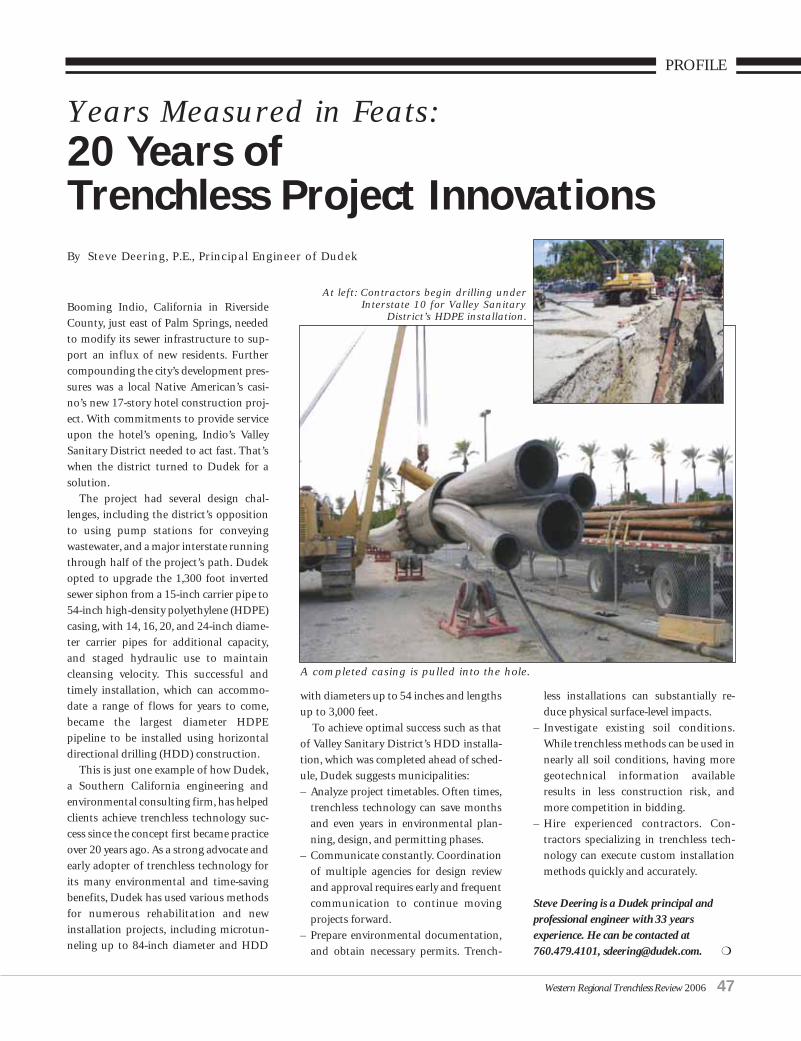
Western Regional Trenchless Review 2006 47
PROFILE
Booming Indio, California in RiversideCounty, just east of Palm Springs, neededto modify its sewer infrastructure to sup-port an influx of new residents. Furthercompounding the city’s development pres-sures was a local Native American’s casi-no’s new 17-story hotel construction proj-ect. With commitments to provide serviceupon the hotel’s opening, Indio’s ValleySanitary District needed to act fast. That’swhen the district turned to Dudek for asolution.
The project had several design chal-lenges, including the district’s oppositionto using pump stations for conveyingwastewater, and a major interstate runningthrough half of the project’s path. Dudekopted to upgrade the 1,300 foot invertedsewer siphon from a 15-inch carrier pipe to54-inch high-density polyethylene (HDPE)casing, with 14, 16, 20, and 24-inch diame-ter carrier pipes for additional capacity,and staged hydraulic use to maintaincleansing velocity. This successful andtimely installation, which can accommo-date a range of flows for years to come,became the largest diameter HDPEpipeline to be installed using horizontaldirectional drilling (HDD) construction.
This is just one example of how Dudek,a Southern California engineering andenvironmental consulting firm, has helpedclients achieve trenchless technology suc-cess since the concept first became practiceover 20 years ago. As a strong advocate andearly adopter of trenchless technology forits many environmental and time-savingbenefits, Dudek has used various methodsfor numerous rehabilitation and newinstallation projects, including microtun-neling up to 84-inch diameter and HDD
with diameters up to 54 inches and lengthsup to 3,000 feet.
To achieve optimal success such as thatof Valley Sanitary District’s HDD installa-tion, which was completed ahead of sched-ule, Dudek suggests municipalities:– Analyze project timetables. Often times,
trenchless technology can save monthsand even years in environmental plan-ning, design, and permitting phases.
– Communicate constantly. Coordinationof multiple agencies for design reviewand approval requires early and frequentcommunication to continue movingprojects forward.
– Prepare environmental documentation,and obtain necessary permits. Trench-
less installations can substantially re-duce physical surface-level impacts.
– Investigate existing soil conditions.While trenchless methods can be used innearly all soil conditions, having moregeotechnical information availableresults in less construction risk, andmore competition in bidding.
– Hire experienced contractors. Con-tractors specializing in trenchless tech-nology can execute custom installationmethods quickly and accurately.
Steve Deering is a Dudek principal andprofessional engineer with 33 yearsexperience. He can be contacted at760.479.4101, [email protected]. ❍
Years Measured in Feats:20 Years ofTrenchless Project InnovationsBy Steve Deering, P.E., Principal Engineer of Dudek
At left: Contractors begin drilling underInterstate 10 for Valley Sanitary
District’s HDPE installation.
A completed casing is pulled into the hole.

PROFILE
Materials to Protect and RestoreWastewater Infrastructure
Sauereisen continues to innovate withmaterials and application methods for themunicipal wastewater industry. The com-pany’s materials prevent corrosion to vul-nerable concrete and steel infrastructure.In addition, Sauereisen products prohibitwater inflow & infiltration, a prevalentproblem in wastewater collection systems.
Since entering the wastewater marketover 30 years ago, the company’s credibili-ty has grown one project at a time. Its ear-liest installations involved dual lining pro-tection using an impermeable urethanemembrane beneath a gunite-applied, acid-
resistant refractory. The silicate-formulat-ed refractory offered utility based on itsresistance to full concentrations of sulfu-ric acid.
In time, Sauereisen progressed into
more economical, user-friendly coatingsand linings technology. These incorporat-ed organic polymers specifically formulat-ed for the municipal wastewater environ-ment.
The Sauereisen Research Laboratory’sthorough understanding of the microbio-logically induced corrosion process is thekey to differentiating their linings fromothers. Where other vendors have pursueda coatings “arms race” relative to certainphysical properties, Sauereisen has main-tained its focus on why such materials areneeded in the first place. Their assertion isthat corrosion resistance is the most criti-cal factor in predicting the long-term suc-cess of a material in a chemically aggressiveenvironment.
Consequently, Sauereisen’s epoxy-basedSewerGard 210 family of products wasdesigned to exhibit low permeability. Thisenhances corrosion resistance and extendsthe longevity of underground infrastruc-ture such as manholes and lift stations.SewerGard is available in several variationsto accommodate desired thickness andmethods of application.
One grade of SewerGard may be spin-cast to allow manhole restoration projectsto proceed safely and easily from groundlevel. A trowel, an airless pump, or a rollermay apply other grades of SewerGard.Spray application of SewerGard is ideal forlarger areas and for preventing corrosionin new construction projects. Several treat-ments plants have specified it as part oftheir asset management programs.
Sauereisen’s original No. 210 is one ofthe few epoxy mortars to have stood thetest of time as determined by John
Sauereisen AdvancesAnti-Corrosion TechnologyBy David Snider
You can’t take chances on materials.
With a quarter century of innovation in wastewater, Sauereisen’s protective lining technologies provide grit chambers, sedimentation tanks, and neutralization basins with a seamless barrier against corrosion and abrasion.
Sauereisen. The right protection for big projects.
CALL FOR YOUR CUSTOM PROJECT CONSULTATION TODAY. 412-963-0303 • [email protected]
B I G P R O J E C T S , B I G P R O T E C T I O N .
48 Western Regional Trenchless Review 2006
Spincasting of an epoxy liningin a manhole.

PROFILE
Redner’s corrosion evaluation in LosAngeles during the 1980’s. Since then, thecompany’s material offerings for waste-water have proliferated. In response toregional dilemmas relating to combinedsewer overflow issues, Sauereisen hasintroduced several waterstops, sealants,and complementary substrate repair mate-rials.
Established in 1899, Sauereisen deliversthe credibility that can only be attained bya history of success. From collection sys-tems to treatment plants, Sauereisen offersthe technology and experience to generateconfidence.
SAUEREISEN INC.Contact: Dave Snider160 Gamma DrivePittsburgh, PA 15238-2989Phone: 412.963.0303 Fax: 412.963.7620e-mail: [email protected]
About the Author: David Snider, WesternRegional Manager, Sauereisen, Inc. drawsupon 25 years of experience in his tenurewith Sauereisen. Mr. Snider’s experience asa lab technician, field service rep, materialspecialist, and formulator has prepared himto speak extensively in the corrosion fieldthrough organizations such as NACE,SSPC, and SME.
❍
At left: A severely corroded lift-station prior to restoration. Above: The same lift-station afterrestoration.
Western Regional Trenchless Review 2006 49
Protective epoxy lining applied to thevapor zone of treatment plantinfrastructure.
A manhole cone section with epoxy applied prior toplacement as a means of preventive maintenance.

PROFILE
50 Western Regional Trenchless Review 2006
The Project:Specialized Services (SSC) was hired inApril of 2005 as a sub tier subcontractor bythe Arizona Department of Transporta-tion (ADOT) to install a Siphon underLoop 202, near Interstate 10. The 30-indiameter RGRCP pipe was intended todivert irrigation tail water from a SaltRiver Project retention basin to a pumpstation. The project called for a 502-ft jack& bore to install a 60” diameter casing.
The Company:Before the Siphon project, a 310-ft bore
with a 60-in steel casing was SSC’s longestbore for this size casing, and that wasusing a conventional auger. In this casethey had to increase the length by nearly200-ft, and maintain line and grade to con-nect the basin on the other side of the I10freeway. 39 years of experience in trench-less technology taught them that plan-ning, preparation, and proper equipmentwere critical to success. So after carefullyplotting a pathway under the freeway, theyused an operator controlled BMTA and alaser set up on a fixed-base platform tocontrol the accuracy of the bore. With twofive-man crews working twelve-hour shifts,the bore was expected to take 30 days tocomplete. Then the unexpected happened.
The Challenge:It was slow going for the first 220-ft due
to the hard Arizona soil, but it wasn’t untilthey struck a 56-ft pile of concrete debris,left behind by a previous highway con-
struction crew, that progress came to ascreeching halt. What should have takenthree days turned into a painstaking eight.Large chunks of concrete shredded thecostly bit, forcing SSC to have to removemuch of the debris by hand. Droppingfrom 20-ft to around 7-ft per day, the com-pany was forced to file for a conditionchange with ADOT to try and recoupsome of the rising costs of the delay, whichhad now tolled over $50,000. AlthoughSSC was meticulous in their planning, andSalt River Project thoroughly surveyed thearea, they were still reliant on “as-built”plans, which are notoriously unreliable(and in this case true to form).
The Solution:
Over the years, it has become more andmore unclear as to whose responsibility itis to specify appropriate solutions for spe-cific project conditions. What was onceleft up to the contractor’s discretion hasnow become the role of the design engi-neer, who in many cases has little knowl-edge of trenchless technology.
The Siphon project is just one of manyexamples where contractors have foundthemselves in a similar dilemma, althoughin most cases it is a damaged utility thatcauses the delay, not a pile of concrete.Without proper education and guidance,it is nearly impossible for busy design engi-neers to really understand all the require-ments of trenchless construction.
Hence the birth of Subsurface Utility
SPECIALIZEDSERVICESCOMPANY
Based in Phoenix, Arizona SSC is theleading underground constructionspecialist in the Southwest.
SSC operates three divisions: Direc-tional Drilling, Auger Bore & Tun-neling, and Vacuum Excavating/UtilityPotholing. In addition to a variety ofother trenchless services intended forvarious project conditions.
These include: ❖ Pipe Ramming❖ Pipe Bursting❖ Skidding❖ Large Diameter Tunneling
Complementing its constructionbusiness, the company also offersConsulting and Subsurface UtilityEngineering (S.U.E.) services. ArvidVeidmark III, co-owner and senior esti-mator is a strong advocate of Trench-less Technology and has been consult-ing on these applications since 1997.SSC clients range from large munici-palities to small privately owned com-panies. Their valuable contributionshave helped clients to redesign theirstructures, change their cultures, im-prove customer satisfaction, and in-crease their operational effectiveness.
SSC was founded in 1969, by theVeidmark family. Owners includeMarcia Veidmark, Arvid III, and AaronVeidmark, who all share in the dailyoperation of the company. Over theyears the business has adapted to spe-cialize soley in trenchless technologyand has grown to 34 employees. It isrecognized as the leading authority onArizona’s underground and has beenthe recipient of several awards includ-ing:❖AAAME: Academy for the
Advancement of Small, Minority-and Women-owned Enterprises
❖Phoenix Chamber of Commerce:Small Business Award for “Responseto Adversity”
❖Arizona State University: Spirit ofEnterprise “Emerging EntrepreneurAward” ❍
A Case for S.U.E.By Arvid L. Veidmark, III
An “undisclosed” trash piledelays Specialized Serviceslargest bore project andthreatens a $50,000 loss.
Damaged bit.
Bore tunnel.

Engineering (S.U.E.), a process that accu-rately locates and maps underground util-ities during the early design of a highwayproject. This relatively new branch of engi-neering offers a single, reliable source ofmapping, coordination, assessment, andcommunication to concerned parties. Itcombines traditional methods such asrecords research, plotting, and design withmethodology such as vacuum technologyand utility mapping. Its benefits are enor-mous and it is now recognized as “BestPractice” by the Federal Highway Adminis-tration and the National TransportationBoard, as well as ADOT, who has been uti-lizing a S.U.E. group since 1992.
ADOT’s primary goal is to provide atransportation system that meets theneeds of the citizens of Arizona. This is atall order, considering that Phoenix is oneof the fastest growing cities in the nation.Over a five-year period, ADOT plans tospend over $2.8 billion for highway im-provement projects in Maricopa Countyalone. Considering the fact that for every$1.00 spent on S.U.E., the overall projectcan realize a savings of about $4.62, howmuch can and has been saved on theseprojects? Fortunately for SSC, they wereable to recoup about thirty percent of theirlosses from ADOT, but that is not alwaysthe case.
The Benefits:Even with the problems SSC experi-
enced, the bore was accurate to within 2-inches of its target, and the project was
considered a big success. Without evenrealizing it, SSC had been practicing S.U.E.processes for many years, which turnedout to be a huge benefit for ADOT. Oneexample is how their quality control prac-tices, planning processes, and expertise invacuum technology afforded them theability to avoid a 48” storm drain that wasdirectly in the path of the bore.
Prompted by this situation and theexperiences of others in the field, SSC nowoffers this vital service. SSC is one of thefew companies in Arizona with the in-house staff and equipment to provideSubsurface Utility Engineering. Becauseof this, SSC offers better service, betterquality control, and better value to itsclients in the performance of the S.U.E.process. Owner Arvid Veidmark, III,invests much of his time consulting andeducating engineers and project managerson the benefits of utilizing S.U.E whenspecifying trenchless technology.
Arvid Veidmark is co-owner and estima-tor of Specialized Services, a Phoenix basedunderground construction and consultingcompany, specializing in drilling, boringand vacuum excavation since 1969. Arvidhas more than two decades of operationalexperience and has been consulting since1997 when he succeeded Arvid Jr. as co-owner of SSC. He holds multiple licensesand certifications.
For more information contact:[email protected]/www.sscboring.com602-997-6164
The Federal Highway Administration (FHWA)commissioned Purdue University to find outhow effective SUE is in reducing costs onhighway projects. Free copies of Purdue’sJanuary 2000 report, “Cost Savings onHighway Projects Utilizing SubsurfaceUtility Engineering” Publication No.FHWA-IF-00-014, may be obtained fromFHWA. ❍
Western Regional Trenchless Review 2006 51
Utility pothole. Auger bore.
Water retention basin.

PROFILE
GO TRENCHLESS, YOUNG MAN(And Bring PVC Pipe)By Steven B. Gross, P.E.
Over the years, trenchless technology hasearned acceptance in our industry as amore cost-effective method of pipe instal-lation that causes less disruption to street
traffic, driveways, and landscaping.However, when faced with a wide selectionof materials and processes, not all engi-neers and city officials are 100-percent cer-tain what type of pipe is best suited for aparticular trenchless application. Themain choices are typically thermoplastic(PVC and HDPE) and metallic pipe. Whileit’s true that there are ideal applicationsfor each of these products, it’s a good ideato look at the following factors in order toproperly evaluate the options. Pipe History and PerformanceAlthough metallic pipe has been aroundfor many years, its track record has showna tendency toward corrosion, a major lia-bility. Most reported leaks in pressurized water systems occur in metal pipe due to
corrosion, wasting billions of gallons oftreated water at a significant cost tomunicipalities and homeowners. Corro-sion is not a problem, however, with ther-moplastic materials, as they are non-con-ductors, and are immune to electrochemi-cal reactions caused by acids, bases andsalts. The most widely used thermoplasticmaterial, PVC, has an impressive reputa-tion for longevity, durability, low mainte-nance, and ease of assembly. In sizes 4-inchand larger, about two-thirds of new buriedwater pipe, and at least three-fourths of newburied sanitary sewer pipe, today are PVC.
In the trenchless industry, the first non-metallic, fully corrosion-resistant PVCrestrained-joint piping system was intro-duced in the late 1980s, based on a spline-lock concept originally developed byCertainTeed Corporation in the 1970s. TheCerta-Lok™ system has proven itself notonly in directional drilling applications,with millions of feet successfully installed,but also in other demanding applications,including open trench construction, wherea restrained joint can eliminate the timeand expense of constructing poured con-crete thrust blocks - plus some soil condi-tions will simply not support the use ofthrust blocks. Other critical applicationsinclude above-and-below ground mining,agricultural irrigation, and deep water wells.
HDD installation of 5,124 feet of 20-inch pipeline under the East
Channel of the Susitna River in the Susitna Flats State Game Refuge,
Susitna-Matanuska Valley, Alaska.
ARB, Inc. Lake Forest, California t: 949.598.9242 www.arbinc.com
Gas Distribution . Compressor & Pump Stations
Pipeline Construction . Horizontal Directional Drilling
52 Western Regional Trenchless Review 2006

PROFILE
Today, PVC restrained joint pipe contin-ues to help advance trenchless constructionall over the world. And, the benefits don’tstop with corrosion resistance. Just ask themunicipality of Novato, California, whichrecently relied on trenchless technology uti-lizing 500 feet of 12-inch Certa-Lokrestrained joint PVC pipe. For Novato,trenchless installation of pipe through thetown’s business district greatly minimizedthe headaches pedestrians would have hadwith conventional construction practices.As with numerous other areas of commerceand high-traffic locations that need watermain repairs, the small downtown Novatobusinesses could not afford the disruptionto daily routines that open trench workwould have created.
Restrained joint PVC pipe is also beingused increasingly in pipebursting projects,as fused and strung-out pipe is often notcompatible with the deep-pit space con-straints common with this constructionmethod. Compatibility with Existing Systems
Since most of the U.S. water and sewerpipelines being installed today are nowPVC, it’s natural for a city consideringpipeline replacement or extension throughdirectional drilling processes to want tofollow suit. Pipelines that are exclusivelyPVC function more smoothly, as conven-tional utility components that the cityalready owns can be used for maintenance.Water and sewer projects involving otherpiping materials require that municipali-ties purchase and stock new equipmentand fittings to service the non-standardpipe.
Pressure Handling CapacityOne of the first considerations in the
product evaluation phase of a project is tolook at pressure ratings of competing plas-tic pipe products. Here, great care must beexercised, as thermoplastic materials man-ufactured to AWWA standards are current-ly rated using different systems and safetyfactors, which can result in an unfair com-parison. Using a consistent 2:1 safety fac-tor, higher-strength PVC requires a muchthinner wall than the most common alter-native thermoplastic material in order toachieve the same pressure rating. Becauseof this, a smaller diameter of PVC pipe can
often be used in a project. For example, atransmission line project in the town ofOakland, Tennessee this year was able touse 16-inch Certa-Lok, where it wouldhave had to use 20-inch HDPE pipe to getthe same flow performance. This loweredcosts for the municipality, and enableddirectional drillers to make smaller boresand take up less space. Comparing com-mon sizes and pressure ratings, PVC willalways have a larger inside diameter, whichresults in significantly improved flow per-formance and pumping efficiency.
O Absolutely the widest choice of restrained joint PVC pipe products for directional drilling:
O C900/RJ™ : 4" - 12" (C.I.O.D.) O Yelomine™ : 2" - 16" (IPS O.D.) O Certa-Com™ : 4" - 6" SCH40 conduit
— UL approved!!
O Millions of feet successfully installed for water, sewer, telecom, and electrical applications.
O Fully corrosion resistant — no metallic parts or pins.
O Higher strength with thinner walls compared to alternate plastic pipe — improves pumping efficiency!
With Certa-Lok, driveways and streets remain clear and open!• 20' lengths conveniently assemble one joint at a time, as the pipe
is being pulled back• No need for time-consuming and costly heat-fusion operations• Great in congested areas where there is no room for bulky reels or to
string out hundreds of feet of pipe
with your choice of pipe for directional drilling!
Specify Certa-Lok™
Restrained Joint PVC Pipe
Don’t get strung out…
Advantages of CertainTeed Certa-Lok
CertainTeed Corporation, Pipe & Plastics Group, P.O. Box 860, Valley Forge, PA 19482866-CT4-PIPE (866-284-7473), Fax: 610-254-5403 www.certainteed.com
ROOFING • SIDING • WINDOWS • INSULATION • FENCE • DECKING • RAILING • FOUNDATIONS • PIPE
Western Regional Trenchless Review 2006 53

54 Western Regional Trenchless Review 2006
PROFILE
Joint IntegrityFor most installations, this is rarely a
governing factor, as both fusedHDPE/PVC joints and mechanicallyrestrained joints such as Certa-Lok havesufficient strength for most pulls. Whenproperly assembled, both fused and gas-keted restrained-joint systems are leak-freeand have the required pressure integrity.The big difference between the two is thetime and money invested in fusing joints,which requires special equipment andtrained operators. Furthermore, the entirestring of fused pipe needs to be joinedbefore pullback starts. In many urban andcrowded areas, there simply isn’t room todo this, and several hundred feet of streetsand driveways can wind up gettingblocked. With today’s mechanical spline-lock joints, assembly of pipe sections takesplace step-by-step as the pullback contin-ues. This causes considerably less trafficdisruption, and requires a much smallerstaging area. This feature is particularlyimportant where the installation methodinvolves lowering pipe into a deep, narrowpit. In these cases, gasketed restrained-
joint PVC pipe will be the more practicaloption.
Agency ApprovalsAs many water systems have hydrants,
approval of the pipe for use in fire-protec-tion systems is critical. Check to makesure that the pipe you’re considering hasbeen tested and is approved by the recog-nized certifying agencies, typically UL.
ApplicationsAs stated earlier, restrained-joint PVC
has been successfully used for both waterprojects and sanitary sewer systems. PVCpipe is particularly appropriate for applica-tions where sewer specifications require aprecise grade, due to its superior rigidityand beam strength as compared to alter-native plastic pipes. And now, with thecountless documented successes in waterand sewer applications, the industry hasgone on to develop restrained-joint PVCfor telecommunications and electricalprojects as well. So it’s clear to see thatPVC pipe has demonstrated a solid 50-yearhistory throughout North America, and
that manufacturers are committed tointroducing new and innovative productsfor our industry.
For more information on restrained-jointPVC pipe for directional drilling, e-mailSteve Gross at [email protected] or visit www.certainteed.com.For general information on PVC pipe, visitwww.uni-bell.org.
❍
www.gu-international.com
H2S AGGRESSIONCOSTLY REHAB
INFILTRATIONEXFILTRATION
SAVING TAXPAYERS MAINTENANCE MONEY
TESTED AND PROVENJOINT INTEGRITY
LIGHTWEIGHT PVC BARRELAPPROX. 1/9 THAT OF CONCRETE
IDEAL FOR SYSTEMS WITHHIGH H2S LEVELS ORBEYOND PUMP STATIONS
NONOYESYESYESYES
SEALCON LINERSYSTEMS LTD.
26020 31B AvenueAldergrove, B.C. V4W 2Z6
Tel: (604) 607-7755 Fax: (604) 607-7756Email: [email protected]
GU ManholeBase Liner
with 1 PiecePVC Riser

ALBUQUERQUE, NM
Waterline Rehabilitation –Pipe Bursting,Trend of the Future
Improvements were recently made to thewater distribution system in TechnicalArea 1 on Sandia National Laboratories(SNL), utilizing trenchless technology toreplace deteriorated portions of thewaterline throughout the tech area. Atotal of 4,450 LF of 6” to 12” waterlinewas replaced during this project; approx-imately 66% through pipe bursting and34% through open-cut-and-replace.
Due to the number of unknownunderground utilities, with multiple util-ity systems running parallel and crossingeach other, and the close proximity ofthese utilities to the waterline requiringrehabilitation, SNL and AUI used a three-step approach to this project. For eachsegment of pipe to be evaluated for reha-bilitation, the first step was doing aCCTV of the line to determine the condi-tion of the line and any service connec-tions; the second step was determinationif the segment was a candidate for pipebursting; the third step was to potholethe line, find the service connections andutilities in close proximity, and proceedto replace the segment through pipebursting, or through more traditionalmeans if the situation warranted.Through thirty-seven RFI’s, the AUI proj-ect team and the SNL team worked tobuild solutions to problems or questionsdeveloping as the project unfolded.
There were approximately 700 pot-holes through the duration of this proj-ect. At one intersection alone, there were21 undocumented utilities. Upon locat-ing these utilities, AUI would coordinatewith SNL representatives to get a GPSreading on the utility line, determine ifthe line was active or inactive, and addthe line to the as-built documents for thisproject. Each situation concerning anunknown underground facility presentedunique challenges, including the need forpenetration permits, and modification tothe proposed waterline installation planto avoid conflicts with these facilities.
— 30 LF 6” HDPEWaterline Pipe Burst
— 1,422 LF 8” to 10” HDPEWaterline Pipe Burst
— 1,515 LF 10” to 12” HDPEWaterline Pipe Burst
— 915 LF 8” DI WaterlineOpen-Cut-and-Replace
— 355 LF 10” DI WaterlineOpen-Cut-and-Replace
— 213 LF 12” DI WaterlineOpen-Cut-and-Replace
— 4,568 LF CCTV of Waterline
Western Regional Trenchless Review 2006 55

AUI and Southwest Sewer Service (thesubcontractor providing CCTV services)worked closely with the SNL project engi-neers to determine which lines weresound, which lines would be replacedthrough pipe bursting, and which wouldbe replaced by other means. This threestep process did present some challengesthrough the first few segments of pipe,but the SNL/AUI/Subcontractor teamsoon fell into a process groove thatallowed one segment of pipe to be start-ed, while another was finishing with reha-bilitation.
This project occurred throughoutTechnical Area 1 on various streets heavi-ly traveled by both vehicles and pedestri-ans, near SNL employee work areas andparking lots. The AUI team was chal-lenged with keeping traffic flowing, keep-ing the affected work areas and employ-ees informed, maintaining safety andspace for pedestrians, and promotingconstruction area safety awareness forthose who might find themselves in theconstruction area.
Throughout this project, maintainingwater service to offices and laboratories
was a critical issue. AUI was able towork out a schedule with the SNL rep-resentatives, so that the shoo-fly orbypass waterlines could be set in place,and water service to these facilitieswould only be interrupted long enoughto connect into these temporary lines(less than 2 hours). The process wouldbe reversed to re-connect the facilitiesto the water distribution system oncethe waterline serving the facility wasreplaced.
Although only about one half of theoriginally intended footage (approxi-mately 5,500 LF) of pipe was actuallyreplaced through pipe bursting, AUIcounts this project among its successes.Our work on this project proves thatwhen existing conditions are right, pipebursting is quicker, and more cost effec-tive, than the traditional open-cut-and-replace method. We have learned, alongwith the SNL engineers on this project,that pipe bursting is not the most effec-tive choice for pipe replacement in areaswith significant numbers of unknownutilities, numerous utility crossings, orwhere the distance between utility lines is
minimal or unknown. AUI is proud tohave participated in this project for SNL,which was an adventure into utilizingtrenchless technology as an efficient andeffective means of rehabilitating water-line in a highly congested area, for whichmaintaining the water supply was a cru-cial issue.
For further information or projectinquiries, please contact AUI Inc.Trenchless Manager Michael RoccoEmail: [email protected] Phone: 505-242-4848 ext. 3004 Mobile Phone: 505-975-6999 ❍
56 Western Regional Trenchless Review 2006
PRIMELINE PRODUCTS, INC.ALTAMONTE SPRINGS, FL 32714
INTRODUCING THE ENGINEERED APPROACH TO LATERAL LINING
The PRIMELINER® Lateral Lining System• User friendly
• No license or territory fees
• No minimum purchases
• Proven technology
• On-the-job training
• Full technical support
• Variety of tube styles to suit your job
• Rehabilitate all types of pipe
• Stop root intrusion
PRIMELINER® Uses Silicate or Epoxy Resins
Ambient Cure - No Steam or Hot Water NeededAdjustable Working/Setting Times Non-Shrinking
No Styrene, No VOCsNon-Hazardous - Can Be Shipped by Air
Call Today to See How
Quickly You Can be Lining
Laterals Professionally and
Profitably
TOLL FREE: 877-409-7888
LOCAL & INTERNATIONAL: (407) 772-8131Website: www.primelineproducts.com
e-mail: [email protected]
“We know we have to earn your business every day”
ALBUQUERQUE, NM
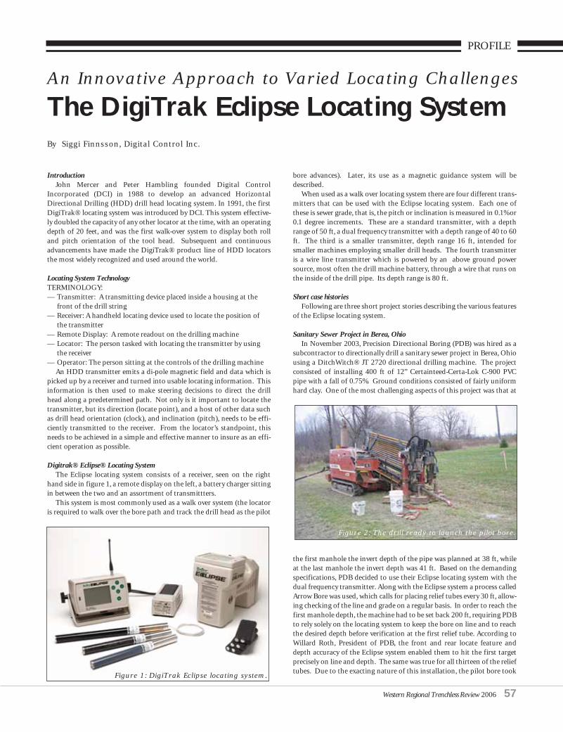
PROFILE
An Innovative Approach to Varied Locating Challenges
The DigiTrak Eclipse Locating SystemBy Siggi Finnsson, Digital Control Inc.
IntroductionJohn Mercer and Peter Hambling founded Digital Control
Incorporated (DCI) in 1988 to develop an advanced HorizontalDirectional Drilling (HDD) drill head locating system. In 1991, the firstDigiTrak® locating system was introduced by DCI. This system effective-ly doubled the capacity of any other locator at the time, with an operatingdepth of 20 feet, and was the first walk-over system to display both rolland pitch orientation of the tool head. Subsequent and continuousadvancements have made the DigiTrak® product line of HDD locatorsthe most widely recognized and used around the world.
Locating System Technology TERMINOLOGY:— Transmitter: A transmitting device placed inside a housing at the
front of the drill string— Receiver: A handheld locating device used to locate the position of
the transmitter— Remote Display: A remote readout on the drilling machine— Locator: The person tasked with locating the transmitter by using
the receiver— Operator: The person sitting at the controls of the drilling machine
An HDD transmitter emits a di-pole magnetic field and data which ispicked up by a receiver and turned into usable locating information. Thisinformation is then used to make steering decisions to direct the drillhead along a predetermined path. Not only is it important to locate thetransmitter, but its direction (locate point), and a host of other data suchas drill head orientation (clock), and inclination (pitch), needs to be effi-ciently transmitted to the receiver. From the locator’s standpoint, thisneeds to be achieved in a simple and effective manner to insure as an effi-cient operation as possible.
Digitrak® Eclipse® Locating SystemThe Eclipse locating system consists of a receiver, seen on the right
hand side in figure 1, a remote display on the left, a battery charger sittingin between the two and an assortment of transmittters.
This system is most commonly used as a walk over system (the locatoris required to walk over the bore path and track the drill head as the pilot
bore advances). Later, its use as a magnetic guidance system will bedescribed.
When used as a walk over locating system there are four different trans-mitters that can be used with the Eclipse locating system. Each one ofthese is sewer grade, that is, the pitch or inclination is measured in 0.1% or0.1 degree increments. These are a standard transmitter, with a depthrange of 50 ft, a dual frequency transmitter with a depth range of 40 to 60ft. The third is a smaller transmitter, depth range 16 ft, intended forsmaller machines employing smaller drill heads. The fourth transmitteris a wire line transmitter which is powered by an above ground powersource, most often the drill machine battery, through a wire that runs onthe inside of the drill pipe. Its depth range is 80 ft.
Short case historiesFollowing are three short project stories describing the various features
of the Eclipse locating system.
Sanitary Sewer Project in Berea, OhioIn November 2003, Precision Directional Boring (PDB) was hired as a
subcontractor to directionally drill a sanitary sewer project in Berea, Ohiousing a DitchWitch® JT 2720 directional drilling machine. The projectconsisted of installing 400 ft of 12” Certainteed-Certa-Lok C-900 PVCpipe with a fall of 0.75%. Ground conditions consisted of fairly uniformhard clay. One of the most challenging aspects of this project was that at
the first manhole the invert depth of the pipe was planned at 38 ft, whileat the last manhole the invert depth was 41 ft. Based on the demandingspecifications, PDB decided to use their Eclipse locating system with thedual frequency transmitter. Along with the Eclipse system a process calledArrow Bore was used, which calls for placing relief tubes every 30 ft, allow-ing checking of the line and grade on a regular basis. In order to reach thefirst manhole depth, the machine had to be set back 200 ft, requiring PDBto rely solely on the locating system to keep the bore on line and to reachthe desired depth before verification at the first relief tube. According toWillard Roth, President of PDB, the front and rear locate feature anddepth accuracy of the Eclipse system enabled them to hit the first targetprecisely on line and depth. The same was true for all thirteen of the relieftubes. Due to the exacting nature of this installation, the pilot bore took
Figure 1: DigiTrak Eclipse locating system.
Figure 2: The drill ready to launch the pilot bore.
Western Regional Trenchless Review 2006 57
The target’s 100 yards away.
The drill’s alongside the railroad track.
There’s a train coming.
Good thing your HDD equipment is ahead of the curve.
Every job comes with its fair share of pitfalls.And if your equipment isn’t on the cutting edge,then you’re really fighting an uphill battle. That’s why it pays to work with a company like DCI. We continue to push the boundaries of HDD technology and set new standards of ingenuity and innovation for the industry–and for our customers.
In fact, since the introduction of the firstDigiTrak® locating system in 1991, we’ve been arming our customers with the mostrevolutionary HDD equipment found on theplanet. From the locating systems above, to the transmitters below, our full line of intuitive, accurate products and 24/7 customersupport is there to keep your job on track–and help you stay ahead of the curve.
For more information, visit digitrak.com or call us at (800) 288-3610. Because when it comes to getting your jobs done right, we’ve always got our eyes on what’s up ahead. DCI. We’re leaders in the field.
Industry leaders.Passionate visionaries. And genuinely nice guys.
©20
06 D
igita
l Con
trol
, Inc
. All
right
s re
serv
ed.
Digital Control, Inc.
®

Western Regional Trenchless Review 2006 59
PROFILE
about 4 days to complete. After installation,the pipe was inspected and the invert wasfound to be only 0.5” off of the planned depthat the first manhole and about 2” at the finalmanhole. This was more than acceptable tothe project engineer.
Verizon FTTP Project in South Lake, TexasDakota Directional out of Ennis, Texas is a
contractor working on a large FTTP (Fiber ToThe Premise) project for the Verizon telephonecompany. On January 18, 2005 they set up todo a fairly typical bore using their Vermeer®D16x20 drilling machine. This run was toinstall 290 ft of 2” HDPE conduit at a depth of3 ft for a fiber optic line in a residential area.The bore was drilled at an upward slope, gen-erally following the surface, where the eleva-tion at the end of the bore was about 6.2 fthigher than at the entry point. Ground condi-tions consisted of loam, some clay and a rockysection at the beginning of the bore. TheEclipse DataLog feature was used to documentthe bore. Figure 3 shows the bore profile afterdownloading from the Eclipse receiver on thecomputer using the Eclipse DataLog software.
Drilling started in the morning. About 27 ftfrom the starting pit, a gas line at a depth of 6ft had to be crossed. Due to rocky conditionsat the beginning of the bore, the bore path waschanged to get beneath the rocky section. As aresult the bore path ended up being about 2 ftdeeper than planned for the first 10 rods or so,and brought the bore closer to the gas pipethan originally anticipated. Once past therocky section, boring continued without anyproblems. The 290 ft pilot bore was finishedin about 90 minutes. The pullback was com-pleted just before noon, allowing the crew toset up and complete a second similar bore inthe afternoon.
A-12 Highway crossing nearDriebergen, Netherlands
The DigiTrak Eclipse Short Steering Tool(SSTTM) is a magnetic guidance wire line sys-tem designed to work with the Eclipse walkover locating system. The SST transmitterprovides the industry standard guidance toolinformation: roll in 360 distinct increments,inclination in either 0.1% or degree increments,and compass heading (yaw angle), in 0.1 degreeincrements.
Van de Beek BV is an accomplished HDDcontracting firm located in Neerinjen in theNetherlands, and they completed a bore inFebruary 2005 using their Vermeer® D50x100machine and the Eclipse SST system. Theproject called for installing 2 x 6.3 in and 3 x4.9 in conduits underneath the A-12 highwayfor the Enecon utility company. Total lengthof the bore was planned at 590 ft at a maxi-mum depth of 21 ft. Ground conditions con-sisted of fairly uniform, sandy clay. Figure 4shows the SST software screen with the com-pleted bore. The bore plan called for an
approximately 130 ft straight section, a gentleturn to the left, and then straight again for theremainder. While excavating the entry pit, anunmarked power line was discovered on theleft side of the pit, and with trees on the rightside, the machine could not be repositioned.Figure 4. Eclipse SST main screen showing theA-12 highway crossing.
A new reference yaw heading to the left ofthe power line was established and using thewalkover capability, the bore started. Afterabout 65 ft, a right hand turn was started, andusing the Eclipse receiver the tool housing wasguided on to the original heading. The newbore path reached the originally planned path
at about the 180 ft mark. While crossingunder the 6 lane highway, the magnetic head-ing information was used to maintain course.Once across the highway, the magnetic head-ing was verified with the Eclipse receiver.Another power line was discovered at the exit
end, which diverted the bore path about 3.3 ftto the right of the planned exit point. Thefinal feet were drilled and tracked using thewalkover method. The pilot bore was com-pleted in 6 hours, and all 5 conduits bundledtogether were installed in 2 hours, whichincluded pre-reaming.
SummaryThe DigiTrak Eclipse locating system has
been designed to be user friendly, simple touse, very accurate and fast, with a short learn-ing curve allowing locators quick proficiencyin its use. A second consideration is the flexi-bility, allowing the same system to be used on
a multitude of differing projects. By using thesame locating system for most of their diversework, an HDD contractor can have greaterconfidence when tackling more complex proj-ects.
❍
Figure 3: Drill profile report using the Eclipse DataLog software.
Figure 4: Eclipse SST main screen showing the A-12 highway crossing.

PROFILE
Pacific Multilining acquires
New CIPP Lining SystemAfter acquiring the exclusive manufactur-ing and licensing rights to theMultiLiner® Cured-In-Place-Pipe liningsystem in the 13 Western United States,Canada, and Mexico, Pacific MultiliningInc. opened the doors to their 21,000sq.ft. manufacturing facility in 2001.With the vision of supplying a strongerand better alternative to the felt inversionsystem, Pacific Multilining Inc. startedmanufacturing MultiLiner®, a pulled-in-place seamless fibreglass CIPP liner.Pacific Multilining Inc. was the first tointroduce a European-developed fibre-glass CIPP liner into North America.
MultiLiner® is approx. 4 - 5 timesstronger than standard felt CIPP liners,which allows MultiLiner® to use a thin-ner material thickness, resulting in an
overall higher flow capacity in the relinedpipe. On average, MultiLiner® usesapprox. 30% less resin than any felt linerfor the same application.
With a shelf-life after impregnation ofup to 6 weeks, Pacific Multilining Inc. cansupply MultiLiner® pre-impregnated tocontractors throughout North America,allowing contractors to focus solely oninstallation – not the manufacturing orimpregnation process. As Pacific Multi-lining Inc. also rents out the MultiLiner®control equipment necessary for theinstallation, and since boilers very oftencan be rented locally, even smaller con-tractors can use CIPP lining with noinvestment.
MultiLiner® is pulled into place bymeans of a winch, inflated with air, and
cured by a mixture of steam and air, tak-ing approximately 3 hours in smaller andmedium sized diameters. MultiLiner®can be delivered pre-impregnated andready to install in 6” - 48” diameters. Itcan also be cured by means of UV light - acuring technique which allows for evenfaster curing in smaller diameters, and ashelf life of up to 6 months after impreg-nation.
Developed in Europe and successfullyinstalled there since 1993, more than 50%of all CIPP liners installed in Germany aremade of fibreglass, and in Asia fibreglassCIPP liners are gaining ground. Cur-rently, MultiLiner® is also being manu-factured in Singapore and Australia.
Pacific Multilining Inc. continues toincrease their production and number ofcustomers, as the demand seems to benever-ending in a CIPP lining market esti-mated to be approximately 1 Billion US$per year in the US alone, and increasing10 - 15% per year.
More and more cities throughoutNorth America are realizing the numer-ous benefits of trenchless rehabilitation,instead of the old-fashioned open cutmethod, which in most cases is moreexpensive, but also includes significantsocial costs and inconvenience. Cities canstretch their budgets longer, and getmore work done for the same amount ofmoney.
Meanwhile, Pacific Multilining Inc.continues to stretch into new areas look-ing for more contractors to installMultiLiner®.
For further information, contactPacific Multilining Inc.33759 Morey AvenueAbbotsford, B.C.Canada V2S 2W5Ph. 800-864- 9878Fax 604 - 859-1441
❍
Install CIPP liners with NO INVESTMENT!
• 4-5 times STRONGER than any felt CIPP liner
• Delivered PRE-IMPREGNATED with 6 weeks shelf-life
• RENT the installation equipment
• Use YOUR CREW and OUR SPECIALIST!
Pacific Multilining Inc.33759 Morey Ave.Abbotsford, B.C.V2S 2W5, Canada
For more informationcal l us today!
1 800 864 [email protected]
60 Western Regional Trenchless Review 2006

PROFILE
Pipe Genie —
New Pulling ConesSave Time & MoneyFor 15 years, Pipe Genie has been manufacturing innovative
equipment for plumbers based on 30 years experience in plumb-
ing and underground pipe work. As an ongoing effort to improve
the efficiency of trenchless work, Pipe Genie manufactures two
types of patented hybrid pulling cones that save work and time on
the job …’hollow’ and ‘saddle’.
The patented hollow cones allow liquid to flow through the
cone during the pulling operation, allowing contractors to work
in a live line, and eliminate the need for bypass pumps and reduc-
tion in pressure, resulting in a lighter work load on the equip-
ment. The hollow cones are at the heart of Pipe Genie’s patented
upsizing technique. For example, when upsizing a line from 8
inches to 12 inches, debris can flow through the cones and into
the new pipe. After the pulling operation is complete, the
debris is then removed with a high pressure jetter or a hydro
vac system. Furthermore, the hollow cones allow for doubling
up chain or cable when pulling through difficult or unex-
pected conditions, and also have the ability to back the cones
up should an unforeseen obstacle be encountered.
Pipe Genie’s patented saddle cones provide the ability to
pull two sewer or water lines simultaneously in a ‘piggy-back’
configuration, effectively completing two tasks in only one
operation. In both cases, time savings are realized by elimi-
nating steps and reducing job costs. This has the effect of
making quotes more competitive and profit margins healthi-
er.
Pipe Genie manufactures a series of pulling machines, with
power ratings from 20 tons pulling pressure to 240 tons,
allowing the combination of hollow or saddle cones, when
matched with Pipe Genie pulling power, to tackle even the
most challenging situations with relative ease.
The company also manufactures a complete line of acces-
sory items, including two types of pipe cutters, three types of
boring units, a light weight, all-aluminium butt fuser, and
inner bead reamers.
The two models of pipe cutters are “the Slice” and “the Pipe
Shark”. The Slice will easily handle 1” copper pipes with brass
fittings or Schedule 80 gas lines, while the Pipe Shark will cut
the bigger lines, while at the same time irrigating surrounding
soil to reduce compaction.
Boring Units are available in three models … impact (Hammer
Bore), high-pressure water (Hydro Bore), and hydraulic (Pilot
Bore), which can serve dual roles as both a boring machine and a
pulling machine. That way, once the pilot hole has been pushed
through, the machine can then pull the new pipe back!
The new MKII butt fuser has been made lighter and more
portable for ease of use, and once the new pipe is in, the Bead
Demon inner bead reamer (available in 20’ and 40’ kits) will put
the finishing touches on the job!
When it comes to trenchless underground work, Pipe Genie is
the clear leader and innovator, because our equipment is made by
plumbers for plumbers. ❍
Western Regional Trenchless Review 2006 61

INDEX TO ADVERTISERS
62 Western Regional Trenchless Review 2006
Akkerman 15
American Ductile Iron Pipe / American Spiralweld Pipe 8
Ameron International 11
AP/M Permacast/Permaform 24
ARB, Inc. 52
AUI, Inc. 55
Bennett Staheli Engineers 49
Carson Underground, Inc. 16
CertainTeed Corporation 53
Cues 4
DCM Engineering 22
DCI – Digital Control Inc. 58
Drillers Supply 29
Dudek Engineering + Environmental 10
Famhost 17
Geolyn Inc. 3, 32
Horizontal Technology, Inc. IFC
Insituform Technologies Inc. IBC
IPL – International Pipe Lining U.S. Inc. 13
Jacobs Associates 37
National Plant Services, Inc. 43
Novapipe 46
Melfred Borzall Inc. OBC
Michels Corporation 34
Pacific Multilining 60
Pipe Experts 16
Pipe Genie Manufacturing Inc. 61
Primeline Products, Inc. 56
Project Engineering Consultants Ltd. 29
Professional Pipe Services 39
Pure Technologies Ltd. 32
Radius Inc. 62
Rain For Rent 45
Raven Lining Systems 6
Sauereisen 48
Sealcon Liner Systems Ltd. 54
Sekisui SPR Americas, LLC 7
SSC - Specialized Services Co. 51
Sprayroq Protective Lining Systems 9
Trenchless Resource International Inc. 8
TT Technologies, Inc. 41
Vactor 19
Westcon Microtunneling 35

Contrary to popular belief, your constituents don’t always want to see their tax dollars at work.
ELMHURST, ILLINOIS
Constituents are fickle. They want the best public works as long as it doesn’t inconvenience them.Which is why the city of Elmhurst voted for Insituform’s 30 years of trenchless technologyexperience to repair its sewer lines. While digging and replacing sewer lines can take weeks,we had service back up and running before residents got home from work the same day. Nodisruptions. No property restoration. No angry phone calls. And best of all, our speed andexperience meant that Elmhurst’s entire repair efforts were completed on schedule andwithin budget. To see how we can save tax dollars and headaches for your city, call us at800-234-2992 or visit our website at www.insituform.com. Because only our experience shows.
SM
Copyright 2001 Insituform Technologies,® Inc.

yearsNothing bores like a Borzall
GOT A SMALL JOB? WE’VE GOT THEPERFECT TOOLS TO BRING IT ALLDOWN TO SIZE.
You wouldn’t pull out your 3 wood to sink a 4-foot
putt. So why use your big tools for your smallest
jobs? Whether you’re installing fiber to the home or
drilling a short shot from the street to the sidewalk, we
have a complete line of tools that are up to the task, no
matter how under-powered your rig may be. Designed to
maximize efficiency as well as your profitability, our roster of
smaller-sized drill rods, reamers and bits packs a big bite so you
can always make the most of what you’ve got under the hood.
Because the way we see it, there’s no reason for your small jobs
to turn into a big deal. For more information,
give us a call at 1-800-558-7500
(805-614-4344 outside the U.S.).
And let us get your short game on par.
TOOLSFORYOUR
SHORTGAME.
©20
06 M
elfre
d Bo
rzal
l, In
c. 27
12 A
irpar
k Dr
ive,
Sant
a M
aria
, CA
9345
5